JP5994582B2 - Toroidal continuously variable transmission - Google Patents
Toroidal continuously variable transmission Download PDFInfo
- Publication number
- JP5994582B2 JP5994582B2 JP2012244299A JP2012244299A JP5994582B2 JP 5994582 B2 JP5994582 B2 JP 5994582B2 JP 2012244299 A JP2012244299 A JP 2012244299A JP 2012244299 A JP2012244299 A JP 2012244299A JP 5994582 B2 JP5994582 B2 JP 5994582B2
- Authority
- JP
- Japan
- Prior art keywords
- power roller
- traction
- trunnion
- reaction force
- gear
- Prior art date
- Legal status (The legal status is an assumption and is not a legal conclusion. Google has not performed a legal analysis and makes no representation as to the accuracy of the status listed.)
- Expired - Fee Related
Links
Images


Landscapes
- Friction Gearing (AREA)
Description
この発明は、自動車用変速装置として、或いはポンプ等の各種産業用機械の運転速度を調節する為の変速装置として利用する、ハーフトロイダル型のトロイダル型無段変速機の改良に関する。具体的には、各パワーローラ毎のトラクション部のトラクション係数に大きな差が生じる事を防止して、伝達効率の高い構造の実現を図るものである。 The present invention relates to an improvement of a toroidal type continuously variable transmission of a half toroid type that is used as a transmission for an automobile or a transmission for adjusting the operating speed of various industrial machines such as pumps. Specifically, it is possible to prevent a large difference in the traction coefficient of the traction section for each power roller and realize a structure with high transmission efficiency.
自動車用変速装置としてトロイダル型無段変速機を使用する事が、特許文献1〜5等の多くの刊行物に記載されると共に一部で実施されていて周知である。図2〜3は、これら各特許文献に記載されて従来から広く知られているトロイダル型無段変速機の第1例を示している。この従来構造の第1例の場合、入力回転軸1の両端寄り部分の周囲に1対の入力ディスク2a、2bを、それぞれがトロイド曲面である内側面同士を互いに対向させた状態で、前記入力回転軸1と同期した回転を可能に支持している。又、この入力回転軸1の中間部周囲に出力筒3を、この入力回転軸1に対する回転を可能に支持している。又、この出力筒3の外周面には、軸方向中央部に、特許請求の範囲に記載した第一の伝達歯車である出力歯車4を固設すると共に、軸方向両端部に、それぞれが特許請求の範囲に記載した素子である1対の出力ディスク5、5を、スプライン係合により、前記出力筒3と同期した回転を可能に支持している。又、この状態で、それぞれがトロイド曲面である、前記両出力ディスク5、5の内側面を、前記両入力ディスク2a、2bの内側面に対向させている。前記出力歯車4は、特許請求の範囲に記載した第二の伝達歯車である伝達用歯車6と噛合して、前記両出力ディスク5、5の回転を取り出し可能としている。
The use of a toroidal continuously variable transmission as a transmission for an automobile is described in many publications such as Patent Documents 1 to 5 and partially implemented, and is well known. 2 to 3 show a first example of a toroidal-type continuously variable transmission described in these patent documents and widely known in the past. In the case of the first example of this conventional structure, a pair of
又、前記両入力ディスク2a、2bと前記両出力ディスク5、5との間に、それぞれの周面を球状凸面とした複数個のパワーローラ7、7を挟持している。これら各パワーローラ7、7は、それぞれトラニオン8、8に回転自在に支持されており、前記両入力ディスク2a、2bの回転に伴って回転しつつ、これら両入力ディスク2a、2bから前記両出力ディスク5、5に動力を伝達する。即ち、トロイダル型無段変速機の運転時には、駆動軸9により一方(図2の左方)の入力ディスク2aを、押圧装置10を介して回転駆動する。この結果、前記入力回転軸1の両端部に支持された1対の入力ディスク2a、2bが、互いに近づく方向に押圧されつつ同期して回転する。そして、この回転が、前記各パワーローラ7、7を介して前記両出力ディスク5、5に伝わり、前記出力歯車4から取り出される。
Further, a plurality of
前記両入力ディスク2a、2bと前記両出力ディスク5、5との間の変速比を変更する際には、前記各トラニオン8、8の端部に設けた油圧式のアクチュエータ18、18によりこれら各トラニオン8、8を、それぞれの両端部に互いに同心に設けた傾転軸12a、12bの軸方向に変位させる。すると、前記各トラニオン8、8に支持された前記各パワーローラ7、7の周面と前記各ディスク2a、2b、5の側面との転がり接触部である各トラクション部に作用する接線方向の力に、これら各ディスク2a、2b、5の回転方向以外の分力が生じ、この分力により、前記各トラニオン8、8が前記各傾転軸12a、12bを中心として揺動する。そして、これら各トラニオン8、8が所望の変速比を得られるまで揺動した状態で、前記各傾転軸12a、12bの軸方向に関する、前記各トラニオン8、8の位置を中立位置に戻せば、前記変速比が、前記所望の値に保持される。尚、トロイダル型無段変速機の運転時に前記各トラニオン8、8には、前記各パワーローラ7、7から、2Ftと呼ばれる力が加わるが、この力2Ftは、前記各アクチュエータ18、18を構成するピストン19、19が支承する。即ち、これら各アクチュエータ18、18毎に、これら各ピストン19、19を挟む状態で設けた1対ずつの油圧室20a、20b内の油圧同士の間の差△P(低圧側の油圧は開放されるので、実際には高圧側の油圧)と前記各ピストン19、19の受圧面積Sとの積が、前記力2Ftに比例する(2Ft∝△P・S)。尚、これらの点に就いては、トロイダル型無段変速機の技術分野で周知であるから、詳しい説明は省略する。
When changing the gear ratio between the
又、特許文献1には、図4に示す様に、出力ディスク5aとして一体型のものを使用する事により、トロイダル型無段変速機全体として小型・軽量化を図ると共に、押圧装置10aとして油圧式のものを使用した構造が記載されている。この従来構造の第2例の場合、前記出力ディスク5aの外周縁に直接歯を形成し、この出力ディスク5aの外周縁部分を出力歯車4aとしている。そして、この出力歯車4aを、図4には示していない伝達用歯車と噛合させて、前記出力ディスク5aの回転を取り出せる様にしている。前記図4に示した構造は、その他の部分でも前記図2〜3に示した構造と種々相違するが、これらの相違点に就いては、本発明の要旨とは関係しない為、詳しい説明は省略する。
Further, in Patent Document 1, as shown in FIG. 4, by using an integrated output disk 5a, the entire toroidal continuously variable transmission can be reduced in size and weight, and the
何れの構造にしても、トロイダル型無段変速機の運転時には、前記各ディスク2a、2b、5、5aや前記各パワーローラ7、7の弾性変形に基づき、これら各ディスク2a、2b、5、5aの軸方向に関する、これら各パワーローラ7、7の位置が変化する。図2〜3に示した従来構造の第1例の場合には、これら各パワーローラ7、7を前記各トラニオン8、8に対して、基半部と先半部とが互いに偏心した偏心軸11、11と、ラジアル軸受及びスラスト軸受を含む、複数組の転がり軸受とを介して支持する事により、前記各パワーローラ7、7が前記各ディスク2a、2b、5、5aの軸方向に変位するのを許容する様にしている。但し、この様な、構成各部材の弾性変形に拘らず、各ディスクの軸方向に関する各パワーローラの位置を適正に維持する為の構造としては、特許文献2に記載された構造も、従来から知られている。後述する本発明の実施の形態の構造は、この引用文献2に記載された構造を利用するものであるから、この引用文献2に記載された構造に就いて、図5〜8により説明する。この特許文献2に記載されたトロイダル型無段変速機を構成するトラニオン8aは、両端部に互いに同心に設けられた1対の傾転軸12a、12b同士の間に、少なくとも入力、出力各ディスク2a、2b、5、5a(図2、4参照)の径方向(図6〜8の上下方向)に関する内側(図6〜8の上側)の側面を円筒状凸面13とした、支持梁部14を設けている。
In any structure, during operation of the toroidal-type continuously variable transmission, the
この円筒状凸面13の中心軸イは、図6〜8に示す様に、前記両傾転軸12a、12bの中心軸ロと平行で、これら両傾転軸12a、12bの中心軸ロよりも、前記各ディスク2、5の径方向に関して外側(図6〜8の下側)に存在する。又、前記支持梁部14とパワーローラ7の外側面との間に設けるスラスト玉軸受15を構成する外輪16の外側面に、部分円筒面状の凹部17を、この外側面を径方向に横切る状態で設けている。そして、この凹部17と、前記支持梁部14の円筒状凸面13とを係合させ、前記トラニオン8aに対して前記外輪16を、前記各ディスク2a、2b、5、5aの軸方向に関する揺動変位を可能に支持している。
As shown in FIGS. 6 to 8, the central axis A of the
又、前記外輪16の内側面中央部に支持軸21を、この外輪16と一体に固設して、前記パワーローラ7をこの支持軸21の周囲に回転自在に支持している。更に、前記トラニオン8aの内側面のうち、前記支持梁部14の両端部と1対の傾転軸12a、12bとの連続部に、互いに対向する1対の段差面22、22を設けている。そして、これら両段差面22、22と、前記スラスト玉軸受15を構成する外輪16の外周面とを、当接若しくは近接対向させて、前記パワーローラ7からこの外輪16に加わるトラクション力を、何れかの段差面22、22で支承可能としている。
A
上述の図5〜8に示した構造によれば、特許文献2に記載されている様に、前記パワーローラ7を前記各ディスク2a、2b、5、5aの軸方向に変位させて、構成各部材の弾性変形量の変化に拘らず、前記パワーローラ7の周面と前記各ディスク2a、2b、5、5aとの接触状態を適正に維持できる構造を、簡単で低コストに構成できる。
即ち、前記パワーローラ7を前記各ディスク2a、2b、5、5aの軸方向に変位させる必要が生じると、前記外輪16が前記円筒状凸面13の中心軸イを中心として揺動変位する。この揺動変位に基づき、前記パワーローラ7の周面のうちで、前記各ディスク2a、2b、5、5aの軸方向片側面と転がり接触する部分が、これら各ディスク2a、2b、5、5aの軸方向に変位し、前記接触状態を適正に維持する。
According to the structure shown in FIGS. 5 to 8 described above, as described in Patent Document 2, the
That is, when it is necessary to displace the
何れの構造にしても、内側ディスクである、入力回転軸1の中間部周囲に設けた出力ディスク5、5aの軸方向中央部に設けた出力歯車4、4aを通じて、トロイダル型無段変速機にトルクを出し入れする構造の場合、この出力歯車4、4aに加わる歯車反力に基づいて、前記出力ディスク5、5aが径方向に変位する。この歯車反力は、伝達されるトルクと反対方向(接線方向)の反力と、歯面同士の擦れ合いに基づいて生じる径方向の反力とが合成されたもので、例えば前記図2に示した出力歯車4と伝達用歯車6の配列方向(これら両歯車4、6の回転中心を結ぶ方向)に対し傾斜した方向に加わる。
Regardless of the structure, a toroidal continuously variable transmission is formed through the
前記歯車反力が何れの方向に加わるにしても、この歯車反力に基づいて前記出力歯車4、4aの径方向位置が中立位置に対して径方向にずれる。この結果、前記各パワーローラ7、7の周面と前記各ディスク2a、2b、5、5aの転がり接触部である、各トラクション部の面圧が不同になる。具体的には、前記歯車反力が作用する側ではこれら各トラクション部の面圧が高くなり、これと反対側ではこれら各トラクション部の面圧が低くなる。この結果、接線力Ftと法線力Fc(∝面圧)との比であるトラクション係数μt(=Ft/Fc)に、前記歯車反力が作用する側とその反対側とで大きな差が生じる。前記各トラクション部毎にトラクション係数μtが異なると、トロイダル型無段変速機の伝達効率を確保する面から不利になる。具体的には、前記押圧装置10、10aが発生する押圧力が不足する傾向にある場合には、トラクション係数μtが高いトラクション部で過大な滑りが発生する傾向になる。これに対して、トラクション係数μtが高いトラクション部でも過大な滑りが発生しない様に、前記押圧装置10、10aが発生する押圧力を高くすると、トラクション係数μtが低いトラクション部の面圧が過大となり、当該トラクション部で転がり抵抗が増大する。何れの現象も、トロイダル型無段変速機の伝達効率を低下させる為、好ましくない。
Regardless of the direction in which the gear reaction force is applied, the radial position of the
尚、本発明を実施する場合に関連する技術を記載した刊行物として、特許文献3〜6がある。このうちの特許文献3には、トラニオンとパワーローラとを複数組の転がり軸受ユニットを介して組み合わせて成るパワーローラユニットに関して、傾転軸の中心からパワーローラの周面に関するトラクション部の中心までの距離である組立高さを精度良く測定できる方法に就いて記載されている。又、特許文献4〜6には、パワーローラの周面に関するトラクション部のトラクション係数を高くすべく、この周面に微細溝を形成する技術が記載されている。 In addition, there are Patent Documents 3 to 6 as publications describing techniques related to the implementation of the present invention. Among them, Patent Document 3 relates to a power roller unit in which a trunnion and a power roller are combined through a plurality of sets of rolling bearing units, from the center of the tilting shaft to the center of the traction portion on the peripheral surface of the power roller. It describes a method that can accurately measure the assembly height as a distance. Patent Documents 4 to 6 describe techniques for forming fine grooves on the peripheral surface in order to increase the traction coefficient of the traction portion related to the peripheral surface of the power roller.
本発明は、上述の様な事情に鑑み、各パワーローラ毎のトラクション部のトラクション係数に大きな差が生じる事を防止して、伝達効率の高いトロイダル型無段変速機を実現すべく発明したものである。 The present invention was invented to realize a toroidal type continuously variable transmission with high transmission efficiency by preventing the occurrence of a large difference in the traction coefficient of the traction section for each power roller in view of the circumstances as described above. It is.
本発明のトロイダル型無段変速機は、前述した従来から知られているトロイダル型無段変速機と同様に、1対の外側ディスクと、内側ディスクと、第一の伝達歯車と、歯車伝達装置と、複数のトラニオンと、複数のパワーローラと、押圧装置とを備える。
このうちの1対の外側ディスクは、回転軸のうちで軸方向に互いに離隔した2箇所位置に、それぞれが断面円弧形である互いの軸方向片側面同士を対向させた状態で、前記回転軸と同期した回転を自在として支持している。
又、前記内側ディスクは、前記回転軸の中間部周囲に、断面円弧形である軸方向両側面をこれら両外側ディスクの軸方向片側面に対向させた状態で、前記回転軸に対する相対回転を自在に支持されたもので、一体に構成するか、若しくは1対の素子を結合して成る。
又、前記第一の伝達歯車は、前記内側ディスクの軸方向中央部に設けられて、この内側ディスクと同期して回転する。
又、前記歯車伝達装置は、前記第一の伝達歯車と噛合した第二の伝達歯車を含み、前記内側ディスクと前記回転軸と平行に配置された他の回転軸との間でトルクを伝達する。
又、前記各トラニオンは、軸方向に関して前記内側ディスクの軸方向両側面と前記両外側ディスクの軸方向片側面との間位置である1対のキャビティ毎に1対ずつ、それぞれこれら各ディスクの径方向に関して互いに反対側に、前記回転軸に対し捩れの位置にある傾転軸を中心とする揺動変位を自在に設けている。
又、前記各パワーローラは、前記各トラニオンの内側面に回転自在に支持しており、球状凸面としたそれぞれの周面を、前記内側ディスクの軸方向両側面と前記両外側ディスクの軸方向片側面とに当接させている。
更に、前記押圧装置は、前記回転軸と前記両外側ディスクのうちの一方の外側ディスクとの間に設けられ、この一方の外側ディスクを、これら両外側ディスクのうちの他方の外側ディスクに向け押圧する。
The toroidal type continuously variable transmission according to the present invention includes a pair of outer disks, an inner disk, a first transmission gear, and a gear transmission device in the same manner as the previously known toroidal continuously variable transmissions. And a plurality of trunnions, a plurality of power rollers, and a pressing device.
A pair of the outer disks are rotated in a state where the axial side surfaces of the rotating disks are opposed to each other at two positions separated from each other in the axial direction in the rotating shaft. Rotation synchronized with the shaft is supported freely.
In addition, the inner disk rotates relative to the rotating shaft around the middle portion of the rotating shaft, with both axial side surfaces having a circular arc cross section facing one axial side surface of both outer disks. It is supported freely, and is formed as a single unit or by combining a pair of elements.
In addition, the first transmission gear is provided at the center in the axial direction of the inner disk and rotates in synchronization with the inner disk.
The gear transmission device includes a second transmission gear meshed with the first transmission gear, and transmits torque between the inner disk and another rotational shaft arranged in parallel with the rotational shaft. .
Each trunnion has a pair of cavities in the axial direction, each pair of cavities located between both axial side surfaces of the inner disk and one axial side surface of the outer disks. On the opposite sides with respect to the direction, a swinging displacement centering on a tilting shaft that is twisted with respect to the rotating shaft is provided freely.
Each power roller is rotatably supported on the inner side surface of each trunnion, and each circumferential surface formed as a spherical convex surface is formed on both axial sides of the inner disk and axial pieces of the outer disks. It is in contact with the side.
Further, the pressing device is provided between the rotating shaft and one of the two outer disks, and presses the one outer disk toward the other outer disk of the two outer disks. To do.
特に、本発明のトロイダル型無段変速機に於いては、前記各ディスク同士の間でトルクを伝達しないか若しくは伝達するトルクが低い状態(低トルク伝達状態)で、前記各パワーローラの周面に関するトラクション係数を、前記第一、第二の歯車の噛合に基づいて発生し、前記内側ディスクに加わる歯車反力の作用方向に関して互いに異なる位置に存在する前記各パワーローラ同士の間で、互いに異ならせる。
そして、前記トルクが大きくなり、前記歯車反力に基づいて前記内側ディスクが径方向に変位した状態で、前記各トラクション部同士の間のトラクション係数の差を小さくする(理想的には差をゼロにする)。
即ち、前記低トルク伝達状態で、前記歯車反力が作用する側に存在する前記各パワーローラの周面と前記各ディスクの側面との転がり接触部である各トラクション部のトラクション係数を、前記歯車反力が作用する側と反対側に存在する前記各パワーローラの周面と前記各ディスクの側面とのトラクション部のトラクション係数よりも高くする。
尚、本発明で、前記歯車反力が作用する側、或いはこれと反対側に前記各パワーローラが存在する状態とは、必ずしもこの歯車反力の作用方向とこれら各パワーローラの設置位置とが一致していなくても良い。要は、この歯車反力が、一方の側で前記各トラクション部のうちの一部のトラクション部の面圧を高くする方向に作用し、他方の側で残部のトラクション部の面圧を低くする方向に作用する状態であれば、本発明の条件を満たす。
In particular, in the toroidal-type continuously variable transmission according to the present invention, the peripheral surface of each power roller in a state where torque is not transmitted between the disks or in a state where torque transmitted is low (low torque transmission state). The traction coefficient is generated based on the meshing of the first and second gears, and is different from each other between the power rollers existing at different positions with respect to the action direction of the gear reaction force applied to the inner disk. Make it.
Then, when the torque increases and the inner disk is displaced in the radial direction based on the gear reaction force, the difference in traction coefficient between the traction parts is reduced (ideally, the difference is zero). ).
That is, in the low torque transmission state, the traction coefficient of each traction portion that is a rolling contact portion between the peripheral surface of each power roller and the side surface of each disk that is present on the side on which the gear reaction force acts is expressed as the gear. The traction coefficient is set higher than the traction coefficient of the traction portion between the peripheral surface of each power roller and the side surface of each disk existing on the side opposite to the side on which the reaction force acts.
In the present invention, the state in which each power roller is present on the side on which the gear reaction force acts or on the opposite side is not necessarily the direction in which the gear reaction force acts and the installation position of each power roller. It doesn't have to match. In short, this gear reaction force acts on the one side in the direction of increasing the surface pressure of a part of the traction parts, and on the other side, the surface pressure of the remaining traction part is lowered. The condition of the present invention is satisfied as long as it acts in the direction.
上述の様な本発明を実施する場合に具体的には、例えば請求項2〜7に記載した発明の構成を採用できる。これら請求項2〜7に記載した各発明では、各パワーローラユニットの組立高さを規制する。これら各パワーローラユニットとは、それぞれ、トラニオンとパワーローラとを複数組の転がり軸受ユニットを介して組み合わせたユニットである。又、これら各パワーローラユニットの組立高さとは、前記各トラニオンの両端部に互いに同心に設けた、これら各トラニオン毎に1対ずつの傾転軸の中心から、これらトラニオンに支持された各パワーローラの周面に関するトラクション部の中心までの距離を言う。この様なパワーローラユニットの組立高さは、例えば特許文献3に記載された方法により、精度良く測定できる。 Specifically, when implementing the present invention as described above, for example, the configuration of the invention described in claims 2 to 7 can be adopted. In each of these inventions, the assembly height of each power roller unit is regulated. Each of these power roller units is a unit in which a trunnion and a power roller are combined through a plurality of sets of rolling bearing units. The assembly height of each of these power roller units refers to the power supported by these trunnions from the center of one pair of tilting shafts for each trunnion provided concentrically at both ends of each trunnion. The distance to the center of the traction part about the roller circumference. The assembly height of such a power roller unit can be measured with high accuracy by, for example, the method described in Patent Document 3.
そして、請求項2に記載した発明の場合には、前記歯車反力の作用方向に関して、この歯車反力が作用する側と反対側に配置する前記各パワーローラユニットの組立高さを、この歯車反力が作用する側に配置する前記各パワーローラユニットの組立高さよりも高くする。
一方、請求項3〜7に記載した発明の場合には、前記各パワーローラユニットの組立高さを互いに等しくする。
そして、請求項3に記載した発明の場合には、前記歯車反力が作用する側と反対側に配置する前記各パワーローラユニットを、この歯車反力が作用する側に配置する各パワーローラユニットよりも、前記各ディスクの中心軸に近くに配置する。
又、請求項4に記載した発明の場合には、前記歯車反力が作用する側と反対側に配置する前記各パワーローラユニットを構成する前記各パワーローラの周面に、これら各パワーローラの周面に関する各トラクション部のトラクション係数を高くする為の微細溝を形成する。
又、請求項5に記載した発明の場合には、前記歯車反力が作用する側と反対側に配置する前記各パワーローラユニットを構成する前記各パワーローラの周面に関する各トラクション部に供給するトラクションオイルの量を、前記歯車反力が作用する側に配置する前記各パワーローラユニットを構成する前記各パワーローラの周面に関する各トラクション部に供給するトラクションオイルの量よりも多くする。
又、請求項6に記載した発明の場合には、前記歯車反力が作用する側と反対側に配置する前記各パワーローラユニットを構成する前記各パワーローラの周面の母線形状の曲率半径を、前記歯車反力が作用する側に配置する前記各パワーローラユニットを構成する前記各パワーローラの周面の母線形状の曲率半径よりも小さくする。
更に、請求項7に記載した発明の場合には、前記歯車反力が作用する側に配置する前記各パワーローラユニットを前記各傾転軸の軸方向に変位させる為の油圧式のアクチュエータを構成するピストンの受圧面積を、前記歯車反力が作用する側と反対側に配置する前記各パワーローラユニットを前記各傾転軸の軸方向に変位させる為の油圧式のアクチュエータを構成するピストンの受圧面積よりも広くする。
In the case of the invention described in claim 2, the assembly height of each of the power roller units arranged on the side opposite to the side on which the gear reaction force acts is set as the gear height. The assembly height of each of the power roller units disposed on the reaction force acting side is set higher.
On the other hand, in the case of the invention described in claims 3 to 7, the assembly heights of the respective power roller units are made equal to each other.
In the case of the invention described in claim 3, each power roller unit arranged on the side on which the gear reaction force acts is arranged on the side opposite to the side on which the gear reaction force acts on. Rather than the central axis of each disk.
In the case of the invention described in claim 4, the power rollers are arranged on the peripheral surface of the power rollers constituting the power roller units disposed on the side opposite to the side on which the gear reaction force acts. A fine groove is formed to increase the traction coefficient of each traction portion with respect to the peripheral surface.
Also, in the case of the invention described in claim 5, the power roller unit is arranged on the side opposite to the side on which the gear reaction force acts, and is supplied to each traction portion relating to the peripheral surface of each power roller constituting the power roller unit. The amount of traction oil is set to be larger than the amount of traction oil supplied to each traction portion related to the peripheral surface of each power roller that constitutes each power roller unit arranged on the side where the gear reaction force acts.
In the case of the invention described in claim 6, the radius of curvature of the generatrix shape of the peripheral surface of each power roller constituting each power roller unit arranged on the side opposite to the side on which the gear reaction force acts is set. The radius of curvature of the generatrix shape of the peripheral surface of each power roller constituting each power roller unit arranged on the side on which the gear reaction force acts is made smaller.
Furthermore, in the case of the invention described in
上述の様に構成する本発明のトロイダル型無段変速機の場合には、大きなトルク伝達に伴って内側ディスクが径方向に変位した状態で、各トラクション部のトラクション係数を、何れも適正値若しくはこの適正値に近い値にできる。この為、トラクション係数μtが高いトラクション部で過大な滑りが発生したり、トラクション係数μtが低いトラクション部の面圧が過大となって、当該トラクション部で転がり抵抗が増大する事を防止できる。この結果、総てのトラクション部で伝達効率を良好にできて、トロイダル型無段変速機全体としての伝達効率を良好にできる。 In the case of the toroidal-type continuously variable transmission of the present invention configured as described above, the traction coefficient of each traction section is set to an appropriate value or with the inner disk displaced in the radial direction with a large torque transmission. A value close to this appropriate value can be obtained. For this reason, it is possible to prevent an excessive slip from occurring in a traction portion having a high traction coefficient μt, or an increase in rolling resistance in the traction portion due to an excessive surface pressure of the traction portion having a low traction coefficient μt. As a result, transmission efficiency can be improved in all traction sections, and transmission efficiency as a whole toroidal type continuously variable transmission can be improved.
[実施の形態の第1例]
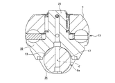
図1を参照しつつ、請求項1、2に対応する、本発明の実施の形態の第1例に就いて説明する。尚、本例を含めて本発明の特徴は、出力ディスク5a等の内側ディスクの軸方向中央部に固設した、出力歯車4a等の第一の伝達歯車からこの内側ディスクに加わる大きな歯車反力に拘らず、トロイダル型無段変速機の各トラクション部での動力伝達を効率良く行わせるべく、各部の寸法や性状、運転条件等に差を設ける点にある。これらの差の絶対値は、前記出力歯車4aを中間部周囲に支持した入力回転軸1の曲げ剛性、トロイダル型無段変速機が伝達するトルクの大きさ、前記出力歯車4aのピッチ円直径及び歯車モジュール等、各種要件により異なる。但し、何れの場合でも、寸法差に関しては、数十μm乃至数百μm程度の小さな値であり、その他の条件に関しても、図面には表れ難い。そして、前記図1自体、基本的には、特許文献1に記載された構造と特許文献2に記載された構造とを組み合わせる事により得られる構造であり、図面からは、本発明の特徴を読み取る事はできない。但し、前記図1を参照する事が、本発明を理解する上で重要であるので、この図1、及び必要に応じて図2〜3を参照しつつ、本例並びに他の実施の形態を説明する。
[First example of embodiment]
A first example of an embodiment of the present invention corresponding to claims 1 and 2 will be described with reference to FIG. The feature of the present invention including this example is that a large gear reaction force applied to the inner disk from the first transmission gear such as the
本例の場合、前記出力歯車4aと伝達用歯車6(図2参照)との噛合に基づいて前記出力ディスク5aに、図1の矢印αで示す様に、同図で下向きの歯車反力が作用するものとする。そこで本例のトロイダル型無段変速機の場合には、各ディスク2a、2b、5a同士の間でトルクを伝達しないか若しくは伝達するトルクが低い状態(低トルク伝達状態)で、各パワーローラ7、7の周面に関するトラクション係数を、前記歯車反力の作用方向に関して互いに異なる位置に存在する前記各パワーローラ7、7同士の間で、互いに異ならせる。
In the case of this example, a downward gear reaction force is applied to the output disk 5a based on the meshing of the
この為に本例の場合には、それぞれがトラニオン8aとパワーローラ7とを複数組の転がり軸受を介して組み合わせたパワーローラユニット23、23の組立高さを規制している。これら各パワーローラユニット23、23の組立高さとは、前記トラニオン8aの両端部に互いに同心に設けた1対の傾転軸12a、12b(図3参照)の中心から、このトラニオン8aに支持されたパワーローラ7の周面に関するトラクション部の中心までの距離を言う。本例の場合には、前記歯車反力が作用する側と反対側である、図1の上側に配置する前記各パワーローラユニット23、23の組立高さHを、この歯車反力が作用する側である、図1の下側に配置する前記各パワーローラユニット23、23の組立高さhよりも高くしている(H>h)。この様なパワーローラユニット23、23の組立高さH、hの調節は、例えば、前記トラニオン8aと、スラスト玉軸受15の外輪16又は玉24、24と、前記パワーローラ7とのうちの少なくとも1種類の部材の、このパワーローラ7の軸方向に関する寸法を変える事により調節する。調節した組立高さH、hの測定は、前述した様に特許文献3に記載された方法により行う。
For this reason, in the case of this example, the assembly height of the
上述の様な本例の構造によれば、前記低トルク伝達状態では、図1の上側(歯車反力の反作用側)に配置した前記各パワーローラユニット23、23を構成する前記各パワーローラ7、7に関するトラクション部の面圧(法線力Fc)が、図1の下側(歯車反力の作用側)のトラクション部の面圧よりも高くなる。本例の場合には、各トラクション部で伝達すべきトルクの大きさ(接線力Ft)は同じである。従って、これら各トラクション部の面圧(∝法線力Fc)が図1の上側で大きく、下側で小さくなる分、上側のトラクション部のトラクション係数μt(=Ft/Fc)が下側のトラクション部のトラクション係数μtよりも小さくなる。
According to the structure of this example as described above, in the low torque transmission state, the
この状態から、前記各ディスク2a、2b、5a同士の間で伝達するトルクが大きくなると、前記歯車反力に基づき、前記出力ディスク5aが径方向に関して、図1の下方に変位する。この結果、前記各パワーローラ7、7のうち、図1の上側に配置された各パワーローラ7、7のトラクション部の面圧が低下し、下側に配置された各パワーローラ7、7のトラクション部の面圧が上昇する。そして、これら各トラクション部のトラクション係数は、図1の上側のトラクション部に関しては上昇し、下側のトラクション部に関しては低下する。この結果、前記各トラクション部同士の間のトラクション係数の差を小さく(理想的には差をゼロに)できる。
From this state, when the torque transmitted between the
この様に本例のトロイダル型無段変速機の場合には、大きなトルク伝達に伴って前記出力ディスク5aが径方向に変位した状態で、前記各トラクション部のトラクション係数を、何れも適正値若しくはこの適正値に近い値にできる。この為、トラクション係数μtが高いトラクション部で過大な滑りが発生したり、トラクション係数μtが低いトラクション部の面圧が過大となって、当該トラクション部で転がり抵抗が増大する事を防止できる。この結果、総てのトラクション部で伝達効率を良好にできて、トロイダル型無段変速機全体としての伝達効率を良好にできる。前記各パワーローラユニット23、23の組立高さH、hの差を適切に規制し、最も使用頻度が多い状態で、前記各トラクション部のトラクション係数μtの差が最小となる様にすれば、前記トロイダル型無段変速機の効率を良好にして、このトロイダル型無段変速機を搭載した車両の燃費性能向上に寄与できる。
Thus, in the case of the toroidal-type continuously variable transmission of this example, the traction coefficient of each of the traction portions is set to an appropriate value or a value with the output disk 5a being displaced in the radial direction with a large torque transmission. A value close to this appropriate value can be obtained. For this reason, it is possible to prevent an excessive slip from occurring in a traction portion having a high traction coefficient μt, or an increase in rolling resistance in the traction portion due to an excessive surface pressure of the traction portion having a low traction coefficient μt. As a result, transmission efficiency can be improved in all traction sections, and transmission efficiency as a whole toroidal type continuously variable transmission can be improved. If the difference between the assembly heights H and h of the respective
[実施の形態の第2例]
次に、請求項1、3に対応する、本発明の実施の形態の第2例に就いて説明する。本例以下の実施の形態では、各パワーローラユニット23、23の組立高さを互いに等しくする。その代わりに本例の場合には、歯車反力の反作用側である、図1の上側に配置する前記各パワーローラユニット23、23を、この歯車反力の作用側である、図1の下側に配置する各パワーローラユニット23、23よりも、各ディスク2a、2b、5aの中心軸に近くに配置する。この為に、各トラニオン8a、8aの両端部に設けた各傾転軸12a、12bを支持する為の支持板25、25に形成した各円孔26、26(図3参照)の位置を異ならせる。具体的には、図1の上側のパワーローラユニット23、23を支持する為の円孔26、26を、同じく下側のパワーローラユニット23、23を支持する為の円孔26、26よりも、入力回転軸1の側に近付ける。
[Second Example of Embodiment]
Next, a second example of the embodiment of the present invention corresponding to claims 1 and 3 will be described. In the following embodiments, the assembly heights of the
本例の場合には、この様な構成により、低トルク伝達状態で、図1の上側(歯車反力の反作用側)に配置した前記各パワーローラユニット23、23を構成する前記各パワーローラ7、7に関するトラクション部の面圧(法線力Fc)を、図1の下側(歯車反力の作用側)のトラクション部の面圧よりも高くする。
その他の部分の構成及び作用は、上述した実施の形態の第1例と同様であるから、重複する説明は省略する。
In the case of this example, the
Since the configuration and operation of the other parts are the same as those in the first example of the above-described embodiment, redundant description is omitted.
[実施の形態の第3例]
次に、請求項1、4に対応する、本発明の実施の形態の第3例に就いて説明する。本例の場合には、歯車反力の反作用側である、図1の上側に配置された前記各パワーローラユニット23、23を構成する各パワーローラ7、7の周面に微細溝を形成する。そして、これら歯車反力の反作用側に配置された各パワーローラ7、7の周面に関する各トラクション部のトラクション係数を高くする。前記歯車反力の作用側である、図1の下側に配置された前記各パワーローラユニット23、23を構成する各パワーローラ7、7の周面に関しては、上述の様な微細溝は形成せず、平滑面のままとする。
[Third example of embodiment]
Next, a third example of the embodiment of the invention corresponding to claims 1 and 4 will be described. In the case of this example, fine grooves are formed on the peripheral surfaces of the
前記各パワーローラ7、7の周面に微細溝を形成する事により、これら各パワーローラ7、7の周面と各ディスク2a、2b、5aの側面との転がり接触部である各トラクション部のトラクション係数が高くなる事は、特許文献4〜6等に記載された通りである。従って、本例の場合には、低トルク伝達状態で、図1の上側(歯車反力の反作用側)に配置した前記各パワーローラユニット23、23を構成する前記各パワーローラ7、7に関するトラクション部のトラクション係数が、図1の下側のトラクション部のトラクション係数よりも高くなる。そして、伝達トルクの増大に伴う前記歯車反力に基づいて前記出力ディスク5aが径方向に関して、図1の下方に変位し、歯車反力の反作用側に存在する、図1の上側のパワーローラ7、7に関するトラクション部の面圧が低下した場合でも、これら各トラクション部で過大な滑りが発生しない様にしている。
その他の部分の構成及び作用は、前述した実施の形態の第1例と同様であるから、重複する説明は省略する。
By forming fine grooves on the peripheral surfaces of the
Since the configuration and operation of the other parts are the same as those in the first example of the above-described embodiment, redundant description is omitted.
[実施の形態の第4例]
請求項1、5に対応する、本発明の実施の形態の第4例に就いて説明する。本例の場合には、歯車反力が作用する側である図1の下側と、これと反対側である図1の上側とに配置する各パワーローラユニット23、23とで、各パワーローラ7、7の周面に関する各トラクション部に供給するトラクションオイルの量を、互いに異ならせている。具体的には、前記歯車反力が作用する側である、図1の下側に配置する前記各パワーローラユニット23、23を構成する前記各パワーローラ7、7の周面に関する各トラクション部に供給するトラクションオイルの量よりも、前記歯車反力が作用する側と反対側である、図1の上側に配置する前記各パワーローラユニット23、23を構成する前記各パワーローラ7、7の周面に関する各トラクション部に供給するトラクションオイルの量を多くする。尚、この様にトラクションオイルの供給量を異ならせる事は、各トラクション部にトラクションオイルを吹き付ける為のノズルの径を変える事により、容易に行える。
[Fourth Example of Embodiment]
A fourth example of the embodiment of the present invention corresponding to claims 1 and 5 will be described. In the case of this example, each
前記各トラクション部のトラクション係数は、これら各トラクション部に存在するトラクションオイルの量(油膜厚さ)に応じて変化する。即ち、前記歯車反力の反作用側のトラクション部に供給するトラクションオイルの量を、この歯車反力の作用側のトラクション部よりも多くする事により、前記歯車反力の反作用側のトラクション部の冷却性を向上させて、この歯車反力の反作用側のトラクション部のトラクション係数を、この歯車反力の作用側よりも高くする。又、これら各トラクション部に十分量のトラクションオイルを供給できれば、当該トラクション部のトラクション係数を確保して、前記歯車反力に基づく出力歯車5aの変位に伴って、この歯車反力が作用する側と反対側で各トラクション部の面圧が低下しても、過大な滑りを生じる事なく、トルクの伝達を行える。
その他の部分の構成及び作用は、前述した実施の形態の第1例と同様であるから、重複する説明は省略する。
The traction coefficient of each of the traction portions changes according to the amount of traction oil (oil film thickness) existing in each of the traction portions. In other words, the amount of traction oil supplied to the traction portion on the reaction side of the gear reaction force is made larger than the traction portion on the reaction side of the gear reaction force, thereby cooling the traction portion on the reaction side of the gear reaction force. The traction coefficient of the traction part on the reaction side of the gear reaction force is made higher than that on the operation side of the gear reaction force. Further, if a sufficient amount of traction oil can be supplied to each of these traction portions, the traction coefficient of the traction portion is ensured, and the side on which the gear reaction force acts as the output gear 5a is displaced based on the gear reaction force. Torque can be transmitted without causing excessive slippage even if the surface pressure of each traction portion decreases on the opposite side.
Since the configuration and operation of the other parts are the same as those in the first example of the above-described embodiment, redundant description is omitted.
[実施の形態の第5例]
請求項1、6に対応する、本発明の実施の形態の第5例に就いて説明する。本例の場合には、歯車反力が作用する側と反対側である、図1の上側に配置する各パワーローラユニット23、23を構成する各パワーローラ7、7の周面の母線形状の曲率半径を、前記歯車反力が作用する側である、図1の下側に配置する各パワーローラユニット23、23を構成する各パワーローラ7、7の周面の母線形状の曲率半径よりも小さくする。従って本例の場合には、これら各パワーローラ7、7の周面と各ディスク2a、2b、5aの側面との転がり接触部であるトラクション部に存在する接触楕円の面積が、前記歯車反力の反作用側である図1の上側で小さく、同じく作用側である下側で大きくなる。この為、前記歯車反力に基づく出力歯車5aの変位に伴って、この歯車反力が作用する側と反対側で各トラクション部の面圧が低下しても、依然として十分な面圧を確保できて、当該トラクション部で過大な滑りを生じる事なく、トルクの伝達を行える。
その他の部分の構成及び作用は、前述した実施の形態の第1例と同様であるから、重複する説明は省略する。
[Fifth Example of Embodiment]
A fifth example of the embodiment of the present invention corresponding to claims 1 and 6 will be described. In the case of this example, the generatrix shape of the peripheral surface of each
Since the configuration and operation of the other parts are the same as those in the first example of the above-described embodiment, redundant description is omitted.
[実施の形態の第6例]
請求項1、7に対応する、本発明の実施の形態の第6例に就いて説明する。本例の場合には、パワーローラユニット23、23を構成する各トラニオン8a、8aを各傾転軸12a、12aの軸方向に変位させる為の油圧式のアクチュエータ18、18を構成するピストン19、19(図3参照)の受圧面積を、歯車反力の作用方向に応じて、互いに異ならせている。具体的には、この歯車反力が作用する側と反対側である、図1の上側のトラニオン8a、8aを変位させる為のアクチュエータ18、18のピストン19、19の受圧面積を、前記歯車反力が作用する側である、図1の下側のトラニオン8a、8aを変位させる為のアクチュエータ18、18のピストン19、19の受圧面積よりも狭くする。
[Sixth Example of Embodiment]
A sixth example of the embodiment of the present invention corresponding to
本例の場合には、大きなトルク伝達時に各トラクション部の面圧が低下する側(前記歯車反力の反作用側)で、各パワーローラに加わる接線方向の力2Ftを小さく抑えられる。この結果、前記歯車反力が作用する側のトラクション部と、同じく作用しない側のトラクション部とで、トラクション係数に大きな差を生じない様にできて、トロイダル型無段変速機全体としての伝達効率の向上を図れる。
その他の部分の構成及び作用は、前述した実施の形態の第1例と同様であるから、重複する説明は省略する。
In the case of this example, the tangential force 2Ft applied to each power roller can be kept small on the side where the surface pressure of each traction portion decreases during transmission of large torque (the reaction side of the gear reaction force). As a result, it is possible to prevent a large difference in the traction coefficient between the traction portion where the gear reaction force acts and the traction portion where the gear reaction force does not act, and the transmission efficiency as a whole toroidal type continuously variable transmission Can be improved.
Since the configuration and operation of the other parts are the same as those in the first example of the above-described embodiment, redundant description is omitted.
トロイダル型無段変速機を、例えば自動車用自動変速機として利用した場合、このトロイダル型無段変速機がトルクを伝達する方向は、加速時と減速時(エンジンブレーキ作動時)とで逆になる。又、トロイダル型無段変速機と遊星歯車式変速機とを組み合わせて構成した無段変速装置の場合、同じ加速時(又は減速時)であっても、トロイダル型無段変速機を通過するトルクの方向が逆転する場合がある。そして、トルクの通過方向が逆転すれば、歯車反力の作用方向も変化する。従って、何れの場合でも、総てのトラクション部のトラクション係数を最適にする事はできない。そこで、本発明を実施する場合には、最も出現頻度が高い運転状態で、総てのトラクション部のトラクション係数を最適にできる様に、各部の寸法や性状、或いはトラクションオイルの供給状態を規制する。 When the toroidal continuously variable transmission is used as an automatic transmission for an automobile, for example, the direction in which the toroidal continuously variable transmission transmits torque is reversed between acceleration and deceleration (when the engine brake is activated). . Further, in the case of a continuously variable transmission configured by combining a toroidal continuously variable transmission and a planetary gear type transmission, the torque that passes through the toroidal continuously variable transmission even during the same acceleration (or deceleration) The direction of may be reversed. And if the direction of the torque passage is reversed, the direction of action of the gear reaction force also changes. Therefore, in any case, the traction coefficient of all traction units cannot be optimized. Therefore, when carrying out the present invention, the dimensions and properties of each part or the supply state of traction oil are regulated so that the traction coefficient of all traction parts can be optimized in the operating state with the highest appearance frequency. .
1 入力回転軸
2a、2b 入力ディスク
3 出力筒
4、4a 出力歯車
5、5a 出力ディスク
6 伝達用歯車
7 パワーローラ
8、8a トラニオン
9 駆動軸
10、10a 押圧装置
11 偏心軸
12a、12b 傾転軸
13 円筒状凸面
14 支持梁部
15 スラスト玉軸受
16 外輪
17 凹部
18 アクチュエータ
19 ピストン
20a、20b 油圧室
21 支持軸
22 段差面
23 パワーローラユニット
24 玉
25 支持板
26 円孔
DESCRIPTION OF SYMBOLS 1
Claims (7)
前記回転軸の中間部周囲に、断面円弧形である軸方向両側面をこれら両外側ディスクの軸方向片側面に対向させた状態で、前記回転軸に対する相対回転を自在に支持された、一体の、若しくは1対の素子を結合して成る内側ディスクと、
この内側ディスクの軸方向中央部に設けられて、この内側ディスクと同期して回転する第一の伝達歯車と、
この第一の伝達歯車と噛合した第二の伝達歯車を含み、前記内側ディスクと前記回転軸と平行に配置された他の回転軸との間でトルクを伝達する歯車伝達装置と、
軸方向に関して前記内側ディスクの軸方向両側面と前記両外側ディスクの軸方向片側面との間位置である1対のキャビティ毎に1対ずつ、それぞれこれら各ディスクの径方向に関して互いに反対側に、前記回転軸に対し捩れの位置にある傾転軸を中心とする揺動変位を自在に設けられた複数のトラニオンと、
これら各トラニオンの内側面に回転自在に支持され、球状凸面としたそれぞれの周面を、前記内側ディスクの軸方向両側面と前記両外側ディスクの軸方向片側面とに当接させた複数のパワーローラと、
前記回転軸と前記両外側ディスクのうちの一方の外側ディスクとの間に設けられ、この一方の外側ディスクを、これら両外側ディスクのうちの他方の外側ディスクに向け押圧する押圧装置とを備えた
トロイダル型無段変速機に於いて、
前記第一、第二の伝達歯車の噛合に基づいて発生し、前記内側ディスクに加わる歯車反力の作用方向に関して、この歯車反力が作用する側に存在する前記各パワーローラの周面と前記各ディスクの側面との転がり接触部である各トラクション部のトラクション係数と、前記歯車反力が作用する側と反対側に存在する前記各パワーローラの周面と前記各ディスクの側面とのトラクション部のトラクション係数とに、前記各ディスク同士の間でトルクを伝達しないか若しくは伝達するトルクが低い状態で差を設け、このトルクが大きくなり、前記歯車反力に基づいて前記内側ディスクが径方向に変位した状態で、前記各トラクション部同士の間のトラクション係数の差を小さくする事を特徴とするトロイダル型無段変速機。 Of the rotating shafts, two positions that are separated from each other in the axial direction are supported so as to freely rotate in synchronization with the rotating shaft, with the respective axial side surfaces facing each other having arcuate cross sections. A pair of outer disks;
Around the intermediate portion of the rotating shaft, the axially opposite side surfaces having a circular arc cross section are opposed to the axially one side surfaces of both outer disks, and are integrally supported to freely rotate relative to the rotating shaft. Or an inner disk formed by combining a pair of elements;
A first transmission gear provided at the axially central portion of the inner disk and rotating in synchronization with the inner disk;
A gear transmission device including a second transmission gear meshed with the first transmission gear, and transmitting torque between the inner disk and another rotational shaft arranged in parallel with the rotational shaft;
One pair for each pair of cavities located between both axial side surfaces of the inner disk and one axial side surface of the outer disks with respect to the axial direction, respectively, opposite to each other with respect to the radial direction of each of these disks, A plurality of trunnions provided freely with swing displacement about a tilting shaft that is twisted with respect to the rotating shaft;
A plurality of powers that are rotatably supported on the inner side surface of each trunnion and have a spherical convex surface contacted with both axial side surfaces of the inner disk and one axial side surface of the outer disks. Laura,
A pressing device provided between the rotating shaft and one outer disk of the two outer disks, and pressing the one outer disk toward the other outer disk of the two outer disks; In toroidal type continuously variable transmissions,
Generated based on the meshing of the first and second transmission gears , and with respect to the acting direction of the gear reaction force applied to the inner disk, the peripheral surface of each power roller present on the side on which the gear reaction force acts and the Traction coefficient of each traction part which is a rolling contact part with the side surface of each disk, and a traction part between the peripheral surface of each power roller and the side surface of each disk existing on the side opposite to the side on which the gear reaction force acts The torque is not transmitted between the disks, or a difference is provided when the transmitted torque is low, and the torque increases, and the inner disk moves in the radial direction based on the gear reaction force. A toroidal continuously variable transmission characterized in that, in a displaced state, a difference in traction coefficient between the traction sections is reduced.
Priority Applications (1)
| Application Number | Priority Date | Filing Date | Title |
|---|---|---|---|
| JP2012244299A JP5994582B2 (en) | 2012-11-06 | 2012-11-06 | Toroidal continuously variable transmission |
Applications Claiming Priority (1)
| Application Number | Priority Date | Filing Date | Title |
|---|---|---|---|
| JP2012244299A JP5994582B2 (en) | 2012-11-06 | 2012-11-06 | Toroidal continuously variable transmission |
Publications (3)
| Publication Number | Publication Date |
|---|---|
| JP2014092253A JP2014092253A (en) | 2014-05-19 |
| JP2014092253A5 JP2014092253A5 (en) | 2015-12-03 |
| JP5994582B2 true JP5994582B2 (en) | 2016-09-21 |
Family
ID=50936471
Family Applications (1)
| Application Number | Title | Priority Date | Filing Date |
|---|---|---|---|
| JP2012244299A Expired - Fee Related JP5994582B2 (en) | 2012-11-06 | 2012-11-06 | Toroidal continuously variable transmission |
Country Status (1)
| Country | Link |
|---|---|
| JP (1) | JP5994582B2 (en) |
Cited By (1)
| Publication number | Priority date | Publication date | Assignee | Title |
|---|---|---|---|---|
| JP7482752B2 (en) | 2020-10-29 | 2024-05-14 | 株式会社Lixil | Corner pieces and panel bodies |
Family Cites Families (3)
| Publication number | Priority date | Publication date | Assignee | Title |
|---|---|---|---|---|
| JPH08159229A (en) * | 1994-11-30 | 1996-06-21 | Mazda Motor Corp | Toroidal type continuously variable transmission |
| JP2000314460A (en) * | 1999-04-30 | 2000-11-14 | Honda Motor Co Ltd | Toroidal type continuosly variable transmission |
| JP2013167344A (en) * | 2012-02-17 | 2013-08-29 | Nsk Ltd | Toroidal type continuously variable transmission |
-
2012
- 2012-11-06 JP JP2012244299A patent/JP5994582B2/en not_active Expired - Fee Related
Cited By (1)
| Publication number | Priority date | Publication date | Assignee | Title |
|---|---|---|---|---|
| JP7482752B2 (en) | 2020-10-29 | 2024-05-14 | 株式会社Lixil | Corner pieces and panel bodies |
Also Published As
| Publication number | Publication date |
|---|---|
| JP2014092253A (en) | 2014-05-19 |
Similar Documents
| Publication | Publication Date | Title |
|---|---|---|
| WO2012111562A1 (en) | Toroidal type continuously variable transmission | |
| JP4905012B2 (en) | Toroidal continuously variable transmission | |
| JP5088303B2 (en) | Toroidal continuously variable transmission | |
| JP5994582B2 (en) | Toroidal continuously variable transmission | |
| JP5007600B2 (en) | Toroidal continuously variable transmission | |
| JP5990921B2 (en) | Toroidal continuously variable transmission | |
| JP2012193793A (en) | Friction roller type reduction gear and electric vehicle drive unit | |
| JP5126206B2 (en) | Toroidal continuously variable transmission | |
| JP5857473B2 (en) | Toroidal continuously variable transmission | |
| JP6508380B2 (en) | Power roller unit for toroidal type continuously variable transmission | |
| JP4019549B2 (en) | Toroidal continuously variable transmission | |
| JP6311452B2 (en) | Toroidal continuously variable transmission | |
| JP6311451B2 (en) | Power roller unit for toroidal type continuously variable transmission | |
| JP5862335B2 (en) | Toroidal continuously variable transmission | |
| JP5673205B2 (en) | Toroidal continuously variable transmission | |
| WO2015052950A1 (en) | Single-cavity toroidal continuously variable transmission | |
| JP6766382B2 (en) | Toroidal continuously variable transmission | |
| JP5830999B2 (en) | Toroidal continuously variable transmission | |
| JP6153498B2 (en) | Toroidal continuously variable transmission | |
| JP4561126B2 (en) | Toroidal continuously variable transmission | |
| JP2003227553A (en) | Toroidal type continuously variable transmission | |
| JP5696586B2 (en) | Toroidal continuously variable transmission | |
| JP5761445B2 (en) | Continuously variable transmission | |
| JP4623365B2 (en) | Toroidal continuously variable transmission | |
| JP5834525B2 (en) | Toroidal continuously variable transmission |
Legal Events
| Date | Code | Title | Description |
|---|---|---|---|
| A521 | Written amendment |
Free format text: JAPANESE INTERMEDIATE CODE: A523 Effective date: 20151019 |
|
| A621 | Written request for application examination |
Free format text: JAPANESE INTERMEDIATE CODE: A621 Effective date: 20151019 |
|
| A977 | Report on retrieval |
Free format text: JAPANESE INTERMEDIATE CODE: A971007 Effective date: 20160715 |
|
| TRDD | Decision of grant or rejection written | ||
| A01 | Written decision to grant a patent or to grant a registration (utility model) |
Free format text: JAPANESE INTERMEDIATE CODE: A01 Effective date: 20160726 |
|
| A61 | First payment of annual fees (during grant procedure) |
Free format text: JAPANESE INTERMEDIATE CODE: A61 Effective date: 20160808 |
|
| R150 | Certificate of patent or registration of utility model |
Ref document number: 5994582 Country of ref document: JP Free format text: JAPANESE INTERMEDIATE CODE: R150 |
|
| LAPS | Cancellation because of no payment of annual fees |