JP5857473B2 - Toroidal continuously variable transmission - Google Patents

Toroidal continuously variable transmission Download PDF

Info

Publication number
JP5857473B2
JP5857473B2 JP2011142932A JP2011142932A JP5857473B2 JP 5857473 B2 JP5857473 B2 JP 5857473B2 JP 2011142932 A JP2011142932 A JP 2011142932A JP 2011142932 A JP2011142932 A JP 2011142932A JP 5857473 B2 JP5857473 B2 JP 5857473B2
Authority
JP
Japan
Prior art keywords
trunnion
outer ring
support beam
disk
beam portion
Prior art date
Legal status (The legal status is an assumption and is not a legal conclusion. Google has not performed a legal analysis and makes no representation as to the accuracy of the status listed.)
Expired - Fee Related
Application number
JP2011142932A
Other languages
Japanese (ja)
Other versions
JP2013011287A5 (en
JP2013011287A (en
Inventor
吉岡 宏泰
宏泰 吉岡
孝昌 田中
孝昌 田中
Current Assignee (The listed assignees may be inaccurate. Google has not performed a legal analysis and makes no representation or warranty as to the accuracy of the list.)
NSK Ltd
Original Assignee
NSK Ltd
Priority date (The priority date is an assumption and is not a legal conclusion. Google has not performed a legal analysis and makes no representation as to the accuracy of the date listed.)
Filing date
Publication date
Application filed by NSK Ltd filed Critical NSK Ltd
Priority to JP2011142932A priority Critical patent/JP5857473B2/en
Publication of JP2013011287A publication Critical patent/JP2013011287A/en
Publication of JP2013011287A5 publication Critical patent/JP2013011287A5/ja
Application granted granted Critical
Publication of JP5857473B2 publication Critical patent/JP5857473B2/en
Expired - Fee Related legal-status Critical Current
Anticipated expiration legal-status Critical

Links

Images

Description

この発明は、例えば車両(自動車)用の自動変速機、建設機械(建機)用の自動変速機、航空機(固定翼機、回転翼機、飛行船等)等で使用されるジェネレータ(発電機)用の自動変速機、ポンプ等の各種産業機械の運転速度を調節する為の自動変速機として利用する、ハーフトロイダル型のトロイダル型無段変速機の改良に関する。   The present invention relates to a generator (generator) used in, for example, an automatic transmission for a vehicle (automobile), an automatic transmission for a construction machine (construction machine), an aircraft (a fixed wing aircraft, a rotary wing aircraft, an airship, etc.), etc. The present invention relates to improvement of a half toroidal toroidal continuously variable transmission that is used as an automatic transmission for adjusting the operating speed of various industrial machines such as automatic transmissions and pumps.

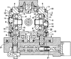
自動車用変速装置としてハーフトロイダル型のトロイダル型無段変速機を使用する事が、特許文献1〜4等の多くの刊行物に記載されると共に一部で実施されていて周知である。又、トロイダル型無段変速機と遊星歯車機構とを組み合わせて変速比の調整幅を広くする構造も、特許文献5等、やはり多くの刊行物に記載されて、従来から広く知られている。図7〜8は、これら各特許文献に記載されて従来から広く知られているトロイダル型無段変速機の第1例を示している。この従来構造の第1例の場合、入力回転軸1の両端寄り部分の周囲に1対の入力ディスク2、2を、それぞれがトロイド曲面である内側面同士を互いに対向させた状態で、前記入力回転軸1と同期した回転を自在に支持している。又、この入力回転軸1の中間部周囲に出力筒3を、この入力回転軸1に対する回転を自在に支持している。又、この出力筒3の外周面には、軸方向中央部に出力歯車4を固設すると共に、軸方向両端部に1対の出力ディスク5、5を、スプライン係合により、前記出力筒3と同期した回転を自在に支持している。又、この状態で、それぞれがトロイド曲面である、前記両出力ディスク5、5の内側面を、前記両入力ディスク2、2の内側面に対向させている。   The use of a half-toroidal toroidal continuously variable transmission as a transmission for an automobile is described in many publications such as Patent Documents 1 to 4 and partially implemented, and is well known. Further, a structure in which a toroidal type continuously variable transmission and a planetary gear mechanism are combined to widen the adjustment range of the gear ratio is also described in many publications such as Patent Document 5 and has been widely known. 7 to 8 show a first example of a toroidal-type continuously variable transmission described in these patent documents and widely known in the past. In the case of the first example of this conventional structure, a pair of input disks 2 and 2 are disposed around the portions near both ends of the input rotation shaft 1 in a state where the inner surfaces, each of which is a toroidal curved surface, face each other. The rotation synchronized with the rotating shaft 1 is freely supported. An output tube 3 is supported around the intermediate portion of the input rotary shaft 1 so as to freely rotate with respect to the input rotary shaft 1. Further, on the outer peripheral surface of the output cylinder 3, an output gear 4 is fixed at the center in the axial direction, and a pair of output disks 5 and 5 are connected to both ends in the axial direction by spline engagement. Supports rotation synchronized with the motor. In this state, the inner surfaces of the output disks 5 and 5, each of which is a toroidal curved surface, are opposed to the inner surfaces of the input disks 2 and 2.

又、前記両入力ディスク2、2と前記両出力ディスク5、5との間に、それぞれの周面を球状凸面とした複数個のパワーローラ6、6を挟持している。これら各パワーローラ6、6は、それぞれトラニオン7、7に回転自在に支持されており、これら各トラニオン7、7は、それぞれ前記各ディスク2、5の中心軸に対し捩れの位置にある傾転軸8、8を中心とする揺動変位自在に支持されている。即ち、これら各トラニオン7、7は、それぞれの軸方向両端部に互いに同心に設けられた1対の傾転軸8、8と、これら各傾転軸8、8同士の間に存在する支持梁部9、9とを備えており、これら各傾転軸8、8が、支持板10、10に対し、ラジアルニードル軸受11、11を介して枢支されている。   Further, a plurality of power rollers 6, 6 each having a spherical convex surface are sandwiched between the input disks 2, 2 and the output disks 5, 5. The power rollers 6 and 6 are rotatably supported by trunnions 7 and 7, respectively. The trunnions 7 and 7 are tilted with respect to the central axes of the disks 2 and 5, respectively. The shafts 8 and 8 are supported so as to be swingable and displaceable. That is, each of the trunnions 7 and 7 includes a pair of tilting shafts 8 and 8 provided concentrically with each other at both axial ends, and a supporting beam existing between the tilting shafts 8 and 8. These tilting shafts 8 and 8 are pivotally supported with respect to the support plates 10 and 10 via radial needle bearings 11 and 11, respectively.

又、前記各パワーローラ6、6は、前記各トラニオン7、7を構成する支持梁部9、9の内側面に、基半部と先半部とが互いに偏心した支持軸12、12と、複数の転がり軸受とを介して、これら各支持軸12、12の先半部回りの回転、及び、これら各支持軸12、12の基半部を中心とする若干の揺動変位自在に支持されている。この様な各パワーローラ6、6の外側面と、前記各トラニオン7、7を構成する支持梁部9、9の内側面との間には、それぞれが前記複数の転がり軸受の一部である、スラスト玉軸受13、13と、スラストニードル軸受14、14とを、前記各パワーローラ6、6の側から順番に設けている。このうちのスラスト玉軸受13、13は、前記各パワーローラ6、6に加わるスラスト方向の荷重を支承しつつ、これら各パワーローラ6、6の回転を許容するものである。これら各スラスト玉軸受13、13は、前記各パワーローラ6、6の外側面に形成された内輪軌道15と、外輪16の内側面に形成された外輪軌道17との間に複数個の玉18、18を、転動自在に設けて成る。又、前記各スラストニードル軸受14、14は、前記各パワーローラ6、6から前記各スラスト玉軸受13、13を構成する外輪16、16に加わるスラスト荷重を支承しつつ、これら各外輪16、16及び前記各支持軸12、12の先半部が、これら各支持軸12、12の基半部を中心に揺動する事を許容するものである。   Each of the power rollers 6 and 6 includes support shafts 12 and 12 in which the base half portion and the tip half portion are eccentric to each other on the inner surface of the support beam portions 9 and 9 constituting the trunnions 7 and 7, respectively. Via a plurality of rolling bearings, the support shafts 12 and 12 are supported so as to be able to rotate around the front half of each of the support shafts 12 and 12 and to be slightly oscillated and displaced about the base half of each of the support shafts 12 and 12. ing. Between the outer side surfaces of the power rollers 6 and 6 and the inner side surfaces of the support beam portions 9 and 9 constituting the trunnions 7 and 7, each is a part of the plurality of rolling bearings. The thrust ball bearings 13 and 13 and the thrust needle bearings 14 and 14 are provided in order from the power rollers 6 and 6 side. Of these, the thrust ball bearings 13, 13 allow the power rollers 6, 6 to rotate while supporting a load in the thrust direction applied to the power rollers 6, 6. Each of these thrust ball bearings 13, 13 has a plurality of balls 18 between an inner ring raceway 15 formed on the outer side surface of each of the power rollers 6, 6 and an outer ring raceway 17 formed on the inner side surface of the outer ring 16. , 18 are provided to be freely rollable. The thrust needle roller bearings 14, 14 support thrust loads applied to the outer rings 16, 16 constituting the thrust ball bearings 13, 13 from the power rollers 6, 6. The front half of each of the support shafts 12 and 12 is allowed to swing around the base half of each of the support shafts 12 and 12.

上述の様なトロイダル型無段変速機の運転時には、駆動軸19により一方(図7の左方)の入力ディスク2を、押圧装置20を介して回転駆動する。この結果、前記入力回転軸1の両端部に支持された1対の入力ディスク2、2が、互いに近づく方向に押圧されつつ同期して回転する。そして、この回転が、前記各パワーローラ6、6を介して前記両出力ディスク5、5に伝わり、前記出力歯車4から取り出される。前記入力回転軸1と前記出力歯車4との間の変速比を変える場合は、油圧式のアクチュエータ21、21により前記各トラニオン7、7を前記各傾転軸8、8の軸方向に変位させる。この結果、前記各パワーローラ6、6の周面と前記各ディスク2、5の内側面との転がり接触部(トラクション部)に作用する、接線方向の力の向きが変化する(転がり接触部にサイドスリップが発生する)。そして、この力の向きの変化に伴って前記各トラニオン7、7が、自身の傾転軸8、8を中心に揺動し、前記各パワーローラ6、6の周面と前記各ディスク2、5の内側面との接触位置が変化する。これら各パワーローラ6、6の周面を、前記両入力ディスク2、2の内側面の径方向外寄り部分と、前記両出力ディスク5、5の内側面の径方向内寄り部分とに転がり接触させれば、前記入力回転軸1と前記出力歯車4との間の変速比が増速側になる。これに対して、前記各パワーローラ6、6の周面を、前記両入力ディスク2、2の内側面の径方向内寄り部分と、前記両出力ディスク5、5の内側面の径方向外寄り部分とに転がり接触させれば、前記入力回転軸1と前記出力歯車4との間の変速比が減速側になる。   During operation of the toroidal-type continuously variable transmission as described above, one input disk 2 (left side in FIG. 7) is rotationally driven by the drive shaft 19 via the pressing device 20. As a result, the pair of input disks 2 and 2 supported at both ends of the input rotating shaft 1 rotate synchronously while being pressed in a direction approaching each other. The rotation is transmitted to the output disks 5 and 5 through the power rollers 6 and 6 and is taken out from the output gear 4. When changing the gear ratio between the input rotary shaft 1 and the output gear 4, the trunnions 7, 7 are displaced in the axial direction of the tilt shafts 8, 8 by hydraulic actuators 21, 21. . As a result, the direction of the tangential force acting on the rolling contact portion (traction portion) between the peripheral surface of each of the power rollers 6 and 6 and the inner surface of each of the disks 2 and 5 changes (in the rolling contact portion). Side slip occurs). As the direction of the force changes, the trunnions 7 and 7 swing around their tilting shafts 8 and 8, and the peripheral surfaces of the power rollers 6 and 6 and the disks 2 and 8. The contact position with the inner surface of 5 changes. The circumferential surfaces of the power rollers 6 and 6 are in rolling contact with the radially outer portions of the inner surfaces of the input disks 2 and 2 and the radially inner portions of the inner surfaces of the output disks 5 and 5. By doing so, the gear ratio between the input rotary shaft 1 and the output gear 4 is increased. On the other hand, the peripheral surfaces of the power rollers 6 and 6 are arranged radially inwardly on the inner side surfaces of the input disks 2 and 2 and radially outwardly on the inner side surfaces of the output disks 5 and 5. If it is brought into rolling contact with the portion, the gear ratio between the input rotary shaft 1 and the output gear 4 becomes the deceleration side.

上述の様なトロイダル型無段変速機の運転時には、動力の伝達に供される各部材、即ち、前記入力、出力各ディスク2、5と前記各パワーローラ6、6とが、前記押圧装置20が発生する押圧力に基づいて弾性変形する。そして、この弾性変形に伴って、前記入力、出力各ディスク2、5が軸方向に変位する。又、前記押圧装置20が発生する押圧力は、前記トロイダル型無段変速機により伝達するトルクが大きくなる程大きくなり、それに伴って前記各部材2、5、6の弾性変形量も多くなる。従って、前記トルクの変動に拘らず、前記入力、出力各ディスク2、5の内側面と前記各パワーローラ6、6の周面との接触状態を適正に維持する為に、前記各トラニオン7、7に対して前記各パワーローラ6、6を、前記各ディスク2、5の軸方向に変位させる機構が必要になる。上述した従来構造の第1例の場合には、前記各パワーローラ6、6を支持した前記各支持軸12、12の先半部を、同じく基半部を中心として揺動変位させる事により、前記各パワーローラ6、6を前記軸方向に変位させる様にしている。   When the toroidal type continuously variable transmission as described above is operated, the members used for power transmission, that is, the input and output disks 2 and 5 and the power rollers 6 and 6 are connected to the pressing device 20. It is elastically deformed based on the pressing force generated. In accordance with this elastic deformation, the input and output disks 2 and 5 are displaced in the axial direction. The pressing force generated by the pressing device 20 increases as the torque transmitted by the toroidal continuously variable transmission increases, and the amount of elastic deformation of the members 2, 5, 6 increases accordingly. Accordingly, in order to properly maintain the contact state between the inner surface of each of the input and output disks 2 and 5 and the peripheral surface of each of the power rollers 6 and 6 regardless of the fluctuation of the torque, the trunnions 7 and 7 7, a mechanism for displacing the power rollers 6 and 6 in the axial direction of the disks 2 and 5 is required. In the case of the above-described first example of the conventional structure, the tip half of each of the support shafts 12 and 12 that support the power rollers 6 and 6 is also oscillated and displaced about the base half as well. The power rollers 6 and 6 are displaced in the axial direction.

上述の様な従来構造の第1例の場合、前記各パワーローラ6、6を前記軸方向に変位させる為の構造が複雑で、部品製作、部品管理、組立作業が何れも面倒になり、コストが嵩む事が避けられない。この様な問題を解決する為の技術として前記特許文献3には、図9〜14に示す様な構造が記載されている。本発明は、この図9〜14に示した従来構造の第2例を改良するものであるから、次に、この従来構造の第2例に就いて説明する。この従来構造の第2例の特徴は、トラニオン7aに対してパワーローラ6aを、入力、出力各ディスク2、5(図7参照)の軸方向の変位を可能に支持する部分の構造にあり、トロイダル型無段変速機全体としての構造及び作用は、前述の図8〜9に示した従来構造の第1例と同様である。   In the case of the first example of the conventional structure as described above, the structure for displacing each of the power rollers 6 and 6 in the axial direction is complicated, and parts manufacturing, parts management, and assembly work are all troublesome and costly. It is inevitable that the volume increases. As a technique for solving such a problem, Patent Document 3 describes a structure as shown in FIGS. Since the present invention improves the second example of the conventional structure shown in FIGS. 9 to 14, the second example of the conventional structure will be described next. The feature of the second example of this conventional structure is the structure of the portion that supports the trunnion 7a so that the power roller 6a can be displaced in the axial direction of the input and output disks 2, 5 (see FIG. 7). The overall structure and operation of the toroidal type continuously variable transmission are the same as those of the first example of the conventional structure shown in FIGS.

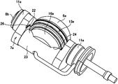
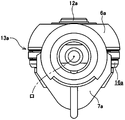
前記従来構造の第2例を構成するトラニオン7aは、両端部に互いに同心に設けられた1対の傾転軸8a、8bと、これら両傾転軸8a、8b同士の間に存在し、少なくとも入力、出力各ディスク2、5(図7参照)の径方向(図10、13〜14の上下方向)に関する内側(図10、13〜14の上側)の側面を円筒状凸面22とした、支持梁部23とを備える。前記両傾転軸8a、8bは、それぞれラジアルニードル軸受11a、11aを介して、支持板10、10(図8参照)に、揺動を可能に支持する。   The trunnion 7a constituting the second example of the conventional structure exists between a pair of tilting shafts 8a and 8b concentrically provided at both ends, and between these tilting shafts 8a and 8b, and at least A support having a cylindrical convex surface 22 on the inner side (upper side in FIGS. 10 and 13 to 14) in the radial direction (up and down direction in FIGS. 10 and 13 to 14) of the input and output disks 2 and 5 (see FIG. 7). And a beam portion 23. Both the tilting shafts 8a and 8b are supported on the support plates 10 and 10 (see FIG. 8) via the radial needle bearings 11a and 11a, respectively, so as to be swingable.

又、前記円筒状凸面22の中心軸イは、図10、13に示す様に、前記両傾転軸8a、8bの中心軸ロと平行で、これら両傾転軸8a、8bの中心軸ロよりも、前記各ディスク2、5の径方向に関して外側(図10、13〜14の下側)に存在する。又、前記支持梁部23とパワーローラ6aの外側面との間に設けるスラスト玉軸受13aを構成する外輪16aの外側面に、部分円筒面状の凹部24を、この外側面を径方向に横切る状態で設けている。そして、この凹部24と、前記支持梁部23の円筒状凸面22とを係合させ、前記トラニオン7aに対して前記外輪16aを、前記各ディスク2、5の軸方向に関する揺動変位を可能に支持している。   Further, as shown in FIGS. 10 and 13, the center axis A of the cylindrical convex surface 22 is parallel to the center axis B of the both tilt axes 8a and 8b, and the center axis B of the both tilt axes 8a and 8b. Rather than the outer side (the lower side of FIGS. 10 and 13 to 14) in the radial direction of the disks 2 and 5. Further, a concave portion 24 having a partially cylindrical surface is radially crossed on the outer surface of the outer ring 16a constituting the thrust ball bearing 13a provided between the support beam portion 23 and the outer surface of the power roller 6a. It is provided in the state. And this recessed part 24 and the cylindrical convex surface 22 of the said support beam part 23 are engaged, and the said outer ring 16a is rockable displacement about the axial direction of each said disks 2 and 5 with respect to the said trunnion 7a. I support it.

又、前記外輪16aの内側面中央部に支持軸12aを、この外輪16aと一体に固設して、前記パワーローラ6aをこの支持軸12aの周囲に、ラジアルニードル軸受25を介して、回転自在に支持している。更に、前記トラニオン7aの内側面のうち、前記支持梁部23の両端部と1対の傾転軸8a、8bとの連続部に、互いに対向する1対の段差面26、26を設けている。そして、これら両段差面26、26と、前記スラスト玉軸受13aを構成する外輪16aの外周面とを、当接若しくは近接対向させて、前記パワーローラ6aからこの外輪16aに加わるトラクション力を、何れかの段差面26、26で支承可能としている。   Further, a support shaft 12a is fixed to the center of the inner surface of the outer ring 16a integrally with the outer ring 16a, and the power roller 6a is rotatable around the support shaft 12a via a radial needle bearing 25. I support it. Furthermore, a pair of stepped surfaces 26 and 26 facing each other are provided on the inner surface of the trunnion 7a at a continuous portion between both end portions of the support beam portion 23 and the pair of tilting shafts 8a and 8b. . Then, these stepped surfaces 26, 26 and the outer peripheral surface of the outer ring 16a constituting the thrust ball bearing 13a are brought into contact with or in close proximity to each other, and any traction force applied from the power roller 6a to the outer ring 16a is selected. These step surfaces 26 and 26 can be supported.

上述の様に構成する従来構造の第2例のトロイダル型無段変速機によれば、前記パワーローラ6aを前記各ディスク2、5の軸方向に変位させて、構成各部材の弾性変形量の変化に拘らず、このパワーローラ6aの周面と前記各ディスク2、5との接触状態を適正に維持できる構造を、簡単で低コストに構成できる。
即ち、トロイダル型無段変速機の運転時に、入力、出力各ディスク2、5、各パワーローラ6a等の弾性変形に基づき、これら各パワーローラ6aをこれら各ディスク2、5の軸方向に変位させる必要が生じると、これら各パワーローラ6aを回転自在に支持している前記スラスト玉軸受13aの外輪16aが、外側面に設けた部分円筒面状の凹部24と支持梁部23の円筒状凸面22との当接面を滑らせつつ、この円筒状凸面22の中心軸イを中心として揺動変位する。この揺動変位に基づき、前記各パワーローラ6aの周面のうちで、前記各ディスク2、5の軸方向片側面と転がり接触する部分が、これら各ディスク2、5の軸方向に変位し、前記接触状態を適正に維持する。
According to the toroidal type continuously variable transmission of the second example of the conventional structure configured as described above, the power roller 6a is displaced in the axial direction of each of the disks 2 and 5, and the amount of elastic deformation of each constituent member is increased. Regardless of the change, a structure capable of appropriately maintaining the contact state between the peripheral surface of the power roller 6a and the disks 2 and 5 can be configured simply and at low cost.
That is, during operation of the toroidal continuously variable transmission, the power rollers 6a are displaced in the axial direction of the disks 2 and 5 based on elastic deformation of the input and output disks 2 and 5 and the power rollers 6a. When necessary, the outer ring 16a of the thrust ball bearing 13a that rotatably supports each of the power rollers 6a is provided with a concave portion 24 having a partial cylindrical surface provided on the outer surface and a cylindrical convex surface 22 of the support beam portion 23. The sliding surface of the cylindrical convex surface 22 is oscillated and displaced about the central axis a. Based on this oscillating displacement, a portion of the peripheral surface of each power roller 6a that is in rolling contact with one axial side surface of each disk 2, 5 is displaced in the axial direction of each disk 2, 5; The contact state is properly maintained.

前述した通り、前記円筒状凸面22の中心軸イは、変速動作の際に各トラニオン7aの揺動中心となる傾転軸8a、8bの中心軸ロよりも、前記各ディスク2、5の径方向に関して外側に存在する。従って、前記円筒状凸面22の中心軸イを中心とする揺動変位の半径は、前記変速動作の際の揺動半径よりも大きく、前記両入力ディスク2、2と前記両出力ディスク5、5との間の変速比の変動に及ぼす影響は少ない(無視できるか、容易に修正できる範囲に留まる)。   As described above, the central axis A of the cylindrical convex surface 22 is larger in diameter than the central axes B of the tilting shafts 8a and 8b, which are the oscillation centers of the trunnions 7a during the shifting operation. Exists with respect to the direction. Therefore, the radius of the rocking displacement about the central axis A of the cylindrical convex surface 22 is larger than the rocking radius at the time of the speed change operation, and both the input disks 2 and 2 and the both output disks 5, 5 Has little effect on the change in the transmission ratio between (and can be neglected or remain within an easily modifiable range).

図9〜14に示した従来構造の第2例の場合、図7〜8に示した同第1例に比べて、部品製作、部品管理、組立作業が何れも容易になり、コスト低廉化を図り易いが、変速動作を安定させる面からは、改良の余地がある。この理由は、前記各支持梁部23を中心とする前記各外輪16aの揺動変位を円滑に行わせる為、これら各支持梁部23の両端部分に1対ずつ設けた、前記各段差面26、26同士の間隔Dを、前記各外輪16aの外径dよりも少し大きく(D>d)する為である。これら各外輪16a、及び、この外輪16aと同心に支持された前記各パワーローラ6aは、前記間隔Dと前記外径dとの差(D−d)分だけ、前記各支持梁部23の軸方向に変位可能になる。   In the case of the second example of the conventional structure shown in FIGS. 9 to 14, parts manufacturing, parts management, and assembly work are all easier than the first example shown in FIGS. Although easy to achieve, there is room for improvement in terms of stabilizing the shifting operation. The reason for this is that each step surface 26 is provided in a pair at each end of each support beam 23 so that the outer ring 16a can be smoothly moved and displaced about each support beam 23. , 26 to make the distance D between the outer rings 16a slightly larger than the outer diameter d (D> d). The outer rollers 16a and the power rollers 6a supported concentrically with the outer ring 16a have shafts of the support beam portions 23 corresponding to a difference (D−d) between the distance D and the outer diameter d. Displaceable in the direction.

一方、トロイダル型無段変速機を搭載した車両の運転時、前記各パワーローラ6aには前記各ディスク2、5から、加速時と減速時(エンジンブレーキの作動時)とで逆方向の力(トロイダル型無段変速機の技術分野で周知の「2Ft」)が加わる。そして、この力2Ftにより、前記各パワーローラ6aが、前記各外輪16aと共に、前記各支持梁部23の軸方向に変位する。この変位の方向は、前述した各アクチュエータ21、21による各トラニオン7、7(図8参照)の変位方向と同じであり、変位量が0.1mm程度であっても、変速動作が開始される可能性を生じる。そして、この様な原因で変速動作が開始された場合には、運転動作とは直接関連しない変速動作となり、何れ修正されるにしても、運転者に違和感を与える。特に、トロイダル型無段変速機が伝達するトルクが低い状態で、上述の様な、運転者が意図しない変速が行われると、運転者に与える違和感が大きくなり易い。   On the other hand, during operation of a vehicle equipped with a toroidal-type continuously variable transmission, each power roller 6a receives a force in the opposite direction from the respective disks 2 and 5 during acceleration and deceleration (when the engine brake is activated) ( "2Ft", which is well known in the technical field of toroidal-type continuously variable transmissions, is added. Then, the force 2Ft causes the power rollers 6a to be displaced in the axial direction of the support beam portions 23 together with the outer rings 16a. The direction of this displacement is the same as the displacement direction of each trunnion 7, 7 (see FIG. 8) by each actuator 21, 21 described above, and the shifting operation is started even when the displacement is about 0.1 mm. Create a possibility. When the shifting operation is started for such a reason, the shifting operation is not directly related to the driving operation, and the driver feels uncomfortable regardless of any correction. In particular, when a shift that is not intended by the driver as described above is performed in a state where the torque transmitted by the toroidal-type continuously variable transmission is low, a sense of discomfort given to the driver tends to increase.

上述の様にして生じる、運転動作とは直接関連しない変速動作の発生を抑える為には、前記間隔Dと前記外径dとの差(D−d)を僅少に(例えば数十μm程度に)抑える事が考えられる。但し、ハーフトロイダル型のトロイダル型無段変速機の運転時には、トラクション部から前記各パワーローラ6a、前記各外輪16aを介して前記各支持梁部23に加わるスラスト荷重により、前記各トラニオン7aが、図15に誇張して示す様に、前記各外輪16aを設置した側が凹となる方向に弾性変形する。そして、この弾性変形の結果、前記各トラニオン7a毎に1対ずつ設けた段差面26、26同士の間隔が縮まる。この様な状態でも、これら両段差面26、26同士の間隔Dが前記各外輪16aの外径d以下にならない様にする為には、通常状態(前記各トラニオン7aが弾性変形していない状態)での、前記間隔Dと前記外径dとの差を、図16(a)に示す様に、或る程度確保する必要があるが、加工精度等により、図16(b)に示す様なトラニオン7aによるパワーローラ6aの挟み込みが発生する可能性がある。   In order to suppress the occurrence of the speed change operation that is not directly related to the driving operation as described above, the difference (D−d) between the distance D and the outer diameter d is made small (for example, about several tens of μm). ) Can be suppressed. However, during the operation of the half-toroidal toroidal continuously variable transmission, each trunnion 7a is caused by a thrust load applied to each support beam portion 23 from the traction portion via each power roller 6a and each outer ring 16a. As exaggeratedly shown in FIG. 15, the side where each outer ring 16a is installed is elastically deformed in a direction in which it becomes concave. As a result of this elastic deformation, the distance between the step surfaces 26, 26 provided in pairs for each trunnion 7a is reduced. Even in such a state, in order to prevent the distance D between the two step surfaces 26 and 26 from becoming smaller than the outer diameter d of each outer ring 16a, the normal state (the state where each trunnion 7a is not elastically deformed). ), The difference between the distance D and the outer diameter d needs to be secured to some extent as shown in FIG. 16A, but as shown in FIG. There is a possibility that the power roller 6a is caught by the trunnion 7a.

特開2003−214516号公報JP 2003-214516 A 特開2007−315595号公報JP 2007-315595 A 特開2008−25821号公報JP 2008-25821 A 特開2008−275088号公報JP 2008-275088 A 特開2004−169719号公報JP 2004-169719 A

本発明は、上述の様な事情に鑑み、コスト低廉化を図り易く、しかも変速動作を安定させられる構造を実現すべく発明したものである。   In view of the circumstances as described above, the present invention has been invented to realize a structure that can easily reduce the cost and stabilize the speed change operation.

本発明のトロイダル型無段変速機は、少なくとも1対のディスクと、複数のトラニオンと、これら各トラニオンと同数のパワーローラと、同じく同数のスラスト転がり軸受とを備える。
特に、本発明のトロイダル型無段変速機に於いては、前記トラニオンと前記外輪との間に、くさび型部材を設けている。そして、前記トラニオンが弾性変形しても、前記トラニオンが前記外輪を挟み込むことなく支承可能としている。
The toroidal-type continuously variable transmission of the present invention includes at least a pair of disks, a plurality of trunnions, the same number of power rollers as each trunnion, and the same number of thrust rolling bearings.
In particular, in the toroidal type continuously variable transmission of the present invention, a wedge-shaped member is provided between the trunnion and the outer ring. And even if the trunnion is elastically deformed, the trunnion can be supported without pinching the outer ring.

上述の様に構成する本発明のトロイダル型無段変速機によれば、コスト低廉化を図り易く、しかも変速動作を安定させられる構造を実現できる。
このうちのコスト低廉化は、前述の図9〜14に示した従来構造の第2例と同様の理由により、図り易い。
又、変速動作の安定化は、前記トラニオンと前記外輪との間に設けたくさび型部材により、前記トラニオンの弾性変形による前記外輪の挟み込みを防止する事により図れる。
According to the toroidal type continuously variable transmission of the present invention configured as described above, it is possible to realize a structure that can easily reduce the cost and stabilize the speed change operation.
Of these, cost reduction is easy to achieve for the same reason as in the second example of the conventional structure shown in FIGS.
Moreover, the speed change operation can be stabilized by preventing the outer ring from being caught by elastic deformation of the trunnion by a wedge-shaped member provided between the trunnion and the outer ring.

本発明の実施の形態の1例を示す、斜視図。The perspective view which shows one example of embodiment of this invention. 図1において、トラニオンからパワーローラユニットを分離した斜視図。The perspective view which isolate | separated the power roller unit from the trunnion in FIG. 図2の正面図。The front view of FIG. 図2のパワーローラを分離したトラニオンを上方から見た平面図。The top view which looked at the trunnion which isolate | separated the power roller of FIG. 2 from upper direction. くさび部材の斜視図。The perspective view of a wedge member. くさび部材の動作を示す図。(a)は動作前、(b)は動作後を示す。The figure which shows operation | movement of a wedge member. (A) shows before operation, and (b) shows after operation. 従来構造の第1例を示す断面図。Sectional drawing which shows the 1st example of a conventional structure. 図7のc−c断面図。Cc sectional drawing of FIG. 従来構造の第2例を示す、スラスト玉軸受を介してパワーローラを支持したトラニオンを、各ディスクの径方向外側から見た斜視図。The perspective view which looked at the trunnion which supported the power roller via the thrust ball bearing which shows the 2nd example of the conventional structure from the radial direction outer side of each disk. 従来構造の第2例において、ディスクの周方向から見た状態で示す正面図。The front view shown in the state seen from the circumferential direction of the disk in the 2nd example of conventional structure. 図10の上方から見た平面図。The top view seen from the upper part of FIG. 図10の右方から見た側面図。The side view seen from the right side of FIG. 図11のd−d断面図。Dd sectional drawing of FIG. 図10のe−e断面図。Ee sectional drawing of FIG. パワーローラから加わるスラスト荷重に基づいてトラニオンが弾性変形した状態を誇張して示す、図11と同方向から見た断面図。The sectional view seen from the same direction as Drawing 11 which exaggerates and shows the state where the trunnion was elastically deformed based on the thrust load added from a power roller. トラニオンによるパワーローラの挟み込みを示す図。The figure which shows the clamping of the power roller by a trunnion.

図1〜5は、本発明の実施の形態の1例を示している。尚、本例の特徴は、変速動作を安定させるべく、各トラニオン7bの支持梁部23に対し、スラスト玉軸受13a(図9〜14参照)を構成する外輪16bを、これら各支持梁部23に対する揺動変位を可能に支持しつつ、トラニオンが弾性変形しても、トラニオンが外輪を挟み込まない様にする為の構造にある。その他の部分の構造及び作用は、前述の図9〜14に示した従来構造の第2例と同様であるから、同等部分に関する図示並びに説明は、省略若しくは簡略にし、以下、本例の特徴部分を中心に説明する。   1 to 5 show an example of an embodiment of the present invention. The feature of this example is that the outer ring 16b constituting the thrust ball bearing 13a (see FIGS. 9 to 14) is provided to the support beam portion 23 of each trunnion 7b to stabilize the speed change operation. The trunnion is configured to prevent the outer ring from being pinched even if the trunnion is elastically deformed while supporting the rocking displacement relative to the outer ring. Since the structure and operation of the other parts are the same as those of the second example of the conventional structure shown in FIGS. 9 to 14 described above, the illustration and description of the equivalent parts are omitted or simplified. The explanation will be focused on.

本例の構造の場合、前記トラニオン7bと前記外輪16bとの間であって、支持梁部23の両端側に、1対のくさび部材27、27を設けている。また図5に示す様に、このくさび部材27、27には、前記トラニオン7bの支持梁部23の円筒状凸面22と係合する、外輪と同様の部分円筒面状の凹部28と、外輪16bの径方向端面に設けた傾斜面29と当接させる、前記トラニオン7bの支持梁部23の中心側からその両端側に向かうにつれて、支持梁部23から離れるように傾斜した傾斜面30と、前記トラニオン7bの段差面26aと当接する当接面31が設けられている。   In the case of the structure of this example, a pair of wedge members 27 and 27 are provided between the trunnion 7 b and the outer ring 16 b and on both ends of the support beam portion 23. Further, as shown in FIG. 5, the wedge members 27, 27 are engaged with the cylindrical convex surface 22 of the support beam portion 23 of the trunnion 7b, and a concave portion 28 having a partial cylindrical surface similar to the outer ring, and the outer ring 16b. An inclined surface 30 that is in contact with an inclined surface 29 provided on the radial end surface of the trunnion 7b and that is inclined away from the support beam portion 23 from the center side of the support beam portion 23 of the trunnion 7b toward the both end sides thereof, A contact surface 31 that contacts the step surface 26a of the trunnion 7b is provided.

このようにくさび部材27、27を設けることで、本例のトロイダル型無段変速機の運転時に、前述した図16に示す様にトラニオンが弾性変形したとしても、図6(b)に示す様にそれぞれのくさび部材27、27の当接面31、31が、前記トラニオン7bの段差面26a、26aに押されることにより、前記トラニオン7bの中心側にスライド移動し、外輪16bをパワーローラ6a側に押し出すので、前記トラニオン7bによる前記外輪16bの挟み込みを防止することができる。また、パワーローラ6aが押し出される移動量と、トラニオン7bが弾性変形による外輪16bの反対側への移動量とが、ある程度相殺されるため、パワーローラ6aとディスクとの接触部の移動量は、従来構造の第1例のトラニオンと比較して少なくなる。   By providing the wedge members 27 and 27 as described above, even when the trunnion is elastically deformed as shown in FIG. 16 during the operation of the toroidal type continuously variable transmission of this example, as shown in FIG. 6B. When the contact surfaces 31, 31 of the wedge members 27, 27 are pushed by the step surfaces 26a, 26a of the trunnion 7b, they slide to the center side of the trunnion 7b, and the outer ring 16b is moved to the power roller 6a side. Therefore, the outer ring 16b can be prevented from being caught by the trunnion 7b. In addition, the amount of movement of the power roller 6a and the amount of movement of the trunnion 7b toward the opposite side of the outer ring 16b due to elastic deformation cancel each other to some extent. Compared with the trunnion of the first example of the conventional structure.

また、くさび型部材27の当接面30には、摩擦係数を低減させる表面処理を施してもよいし、くざび型部材を固体潤滑材により形成してもよい。   Further, the contact surface 30 of the wedge-shaped member 27 may be subjected to a surface treatment for reducing the friction coefficient, or the wedge-shaped member may be formed of a solid lubricant.

また、くざび型部材27の凹部28は、ゴシックアーチ形状としてもよく、このようにすることで、この凹部28の内面とトラニオン7bの支持梁部23に設けた円筒状凸面22とが、これら両面の円周方向に関して2箇所位置で当接する為、これら両面の接触面積を確保して、これら両面の摩耗を抑える事ができる。   Further, the concave portion 28 of the wedge-shaped member 27 may have a Gothic arch shape. By doing so, the inner surface of the concave portion 28 and the cylindrical convex surface 22 provided on the support beam portion 23 of the trunnion 7b Since contact is made at two positions in the circumferential direction of both surfaces, it is possible to secure a contact area between these both surfaces and to suppress wear on both surfaces.

また、トラニオン7bの支持梁部23と外輪16bとの間にパイプ部材32を設けている。パイプ部材32は長円形で、中心部に潤滑油を通過させる為の通孔33を形成している。そして、トラニオン7bの支持梁部23の一部で上流側給油路34の下流端開口部分に、上記パイプ部材32の一方の片半部を嵌合させる為の凹部35を形成しており、外輪16bの下流側給油路36の上流端開口部分に、上記パイプ部材32の他方の片半部を係合させる為の凹部37を形成している。この様なパイプ部材32の一方の片半部を上流側給油路34の下流端開口部分に形成した凹部35に嵌合させた状態で、他方の片半部を下流側給油路36の上流端開口部分に形成した凹部37に、ディスク2、5の弾性変形によりパワーローラ6aが揺動する範囲の変位を可能に、パイプ部材32と凹部37との間に隙間をもたせ係合させている。この様にして、上流側給油路34から下流側給油路36への潤滑供給をパイプ部材32の通孔33を通じて行う。   A pipe member 32 is provided between the support beam portion 23 of the trunnion 7b and the outer ring 16b. The pipe member 32 is oval and has a through hole 33 for allowing the lubricating oil to pass through in the center. A recess 35 for fitting one half of the pipe member 32 is formed in a part of the support beam portion 23 of the trunnion 7b in the downstream end opening portion of the upstream oil supply passage 34. A recess 37 for engaging the other half of the pipe member 32 is formed in the upstream end opening portion of the downstream oil supply passage 36 of 16b. In such a state that one half of the pipe member 32 is fitted in the recess 35 formed in the downstream end opening of the upstream oil supply passage 34, the other half is connected to the upstream end of the downstream oil supply passage 36. The recess 37 formed in the opening portion is engaged with a gap between the pipe member 32 and the recess 37 so that the displacement of the power roller 6a can be displaced by elastic deformation of the disks 2 and 5. In this manner, lubrication is supplied from the upstream oil supply passage 34 to the downstream oil supply passage 36 through the through hole 33 of the pipe member 32.

本発明は、トロイダル型無段変速機単独で実施できる他、特許文献5に記載されている様な、遊星歯車機構と組み合わせた無段変速装置として実施する事もできる。   The present invention can be implemented by a toroidal continuously variable transmission alone, or can be implemented as a continuously variable transmission in combination with a planetary gear mechanism as described in Patent Document 5.

1 入力回転軸
2 入力ディスク
3 出力筒
4 出力歯車
5 出力ディスク
6、6a パワーローラ
7、7a、7b トラニオン
8、8a、8b 傾転軸
9 支持梁部
10 支持板
11 ラジアルニードル軸受
12 支持軸
13 スラスト玉軸受
14 スラストニードル軸受
15 内輪軌道
16、16a、16b 外輪
17 外輪軌道
18 玉
19 駆動軸
20 押圧装置
21 アクチュエータ
22 円筒状凸面
23 支持梁部
24 凹部
25 ラジアルニードル軸受
26、26a 段差面
27 くさび部材
28 凹部
29 傾斜面
30 傾斜面
31 当接面
32 パイプ部材
33 通孔
34 上流側給油路
35 凹部
36 下流側給油路
37 凹部
DESCRIPTION OF SYMBOLS 1 Input rotating shaft 2 Input disk 3 Output cylinder 4 Output gear 5 Output disk 6, 6a Power roller 7, 7a, 7b Trunnion 8, 8a, 8b Tilt shaft 9 Support beam part 10 Support plate 11 Radial needle bearing 12 Support shaft 13 Thrust ball bearing 14 Thrust needle bearing 15 Inner ring raceway 16, 16a, 16b Outer ring 17 Outer ring raceway 18 Ball 19 Drive shaft 20 Press device 21 Actuator 22 Cylindrical convex surface 23 Support beam portion 24 Recess portion 25 Radial needle bearing 26, 26a Stepped surface 27 Wedge Member 28 Concave portion 29 Inclined surface 30 Inclined surface 31 Abutting surface 32 Pipe member 33 Through hole 34 Upstream oil supply passage 35 Concavity 36 Downstream oil supply passage 37 Concavity

Claims (1)

少なくとも1対のディスクと、複数のトラニオンと、これら各トラニオンと同数のパワーローラと、同じく同数のスラスト転がり軸受とを備え、このうちの各ディスクは、それぞれが断面円弧形のトロイド曲面である互いの軸方向片側面同士を対向させた状態で、互いに同心に、相対回転を自在に支持されたものであり、前記各トラニオンは、それぞれの両端部に互いに同心に設けられた1対の傾転軸と、これら両傾転軸同士の間に存在し、少なくとも前記各ディスクの径方向に関する内側の側面を、前記両傾転軸の中心軸と平行でこの傾転軸の中心軸よりも前記各ディスクの径方向に関して外側に存在する中心軸を有する、円筒状凸面とした支持梁部とを備えたもので、軸方向に関して前記各ディスクの軸方向側面同士の間位置の周方向に関して複数箇所に、これら各ディスクの中心軸に対し捩れの位置にある傾転軸を中心とする揺動変位を自在に設けられており、前記各パワーローラは、前記各トラニオンの内側面に、それぞれスラスト転がり軸受を介して回転自在に支持され、球状凸面としたそれぞれの周面を、前記各ディスクの軸方向片側面にそれぞれ当接させており、前記各スラスト転がり軸受は、前記各トラニオンの支持梁部と前記各パワーローラの外側面との間に設けられたもので、これら各支持梁部側に設けられた外輪と、これら各外輪の内側面に設けられた外輪軌道と前記各パワーローラの外側面に設けられた内輪軌道との間に転動自在に、それぞれ複数個ずつ設けられた転動体とを備えたものであり、前記各スラスト転がり軸受の外輪は、これら各外輪の外側面に設けられた凹部と前記各支持梁部の円筒状凸面とを係合させる事により、これら各トラニオンに対し、前記各ディスクの軸方向に関する揺動変位を可能に支持されているトロイダル型無段変速機に於いて、前記トラニオンと前記外輪との間に、くさび型部材を設け、前記くさび型部材には、前記トラニオンの支持梁部の円筒状凸面と係合する部分円筒面状の凹部と、前記スラスト転がり軸受の外輪の径方向端面に設けられた傾斜面と当接する、前記トラニオンの支持梁部の中心側からその端側に向かうにつれて支持梁部から離れるように傾斜した傾斜面と、前記トラニオンの段差面と当接する当接面が設けられていることを特徴とするトロイダル型無段変速機At least one pair of disks, a plurality of trunnions, the same number of power rollers as each of the trunnions, and the same number of thrust rolling bearings are provided, and each of these disks is a toroidal curved surface having an arc cross section. The trunnions are supported concentrically with each other so that relative rotation is freely possible with the axial side surfaces facing each other, and each trunnion is provided with a pair of tilts provided concentrically with each other at both ends. A rotating shaft and between the two tilting shafts, and at least the inner side surface in the radial direction of each disk is parallel to the central axis of the two tilting shafts and more than the central axis of the tilting shaft. And a support beam portion having a cylindrical convex surface having a central axis existing outside in the radial direction of each disk, and in the circumferential direction between the axial side surfaces of each disk in the axial direction. In each of the trunnions, the power rollers are provided at a plurality of locations so as to be freely oscillated and displaced about a tilting shaft that is twisted with respect to the central axis of each disk. The circumferential surface of each disk, which is rotatably supported through a thrust rolling bearing, is in contact with one side surface in the axial direction of each disk, and each thrust rolling bearing is connected to each trunnion. Provided between the support beam portion and the outer surface of each of the power rollers, an outer ring provided on the support beam portion side, an outer ring track provided on the inner side surface of each of the outer rings, A plurality of rolling elements are provided between the outer ring and the inner ring raceway provided on the outer surface of the power roller, and the outer ring of each thrust rolling bearing includes Outside A toroidal-type continuously variable step that is supported so as to be capable of rocking displacement in the axial direction of each disk with respect to each trunnion by engaging a concave portion provided in the cylindrical surface and a cylindrical convex surface of each support beam portion. In the transmission, a wedge-shaped member is provided between the trunnion and the outer ring, and the wedge-shaped member includes a partially cylindrical concave portion that engages with the cylindrical convex surface of the supporting beam portion of the trunnion. An inclined surface that is in contact with an inclined surface provided on a radial end surface of the outer ring of the thrust rolling bearing and is inclined so as to be separated from the support beam portion from the center side of the support beam portion of the trunnion toward the end side thereof; A toroidal continuously variable transmission, characterized in that a contact surface that contacts the step surface of the trunnion is provided .
JP2011142932A 2011-06-28 2011-06-28 Toroidal continuously variable transmission Expired - Fee Related JP5857473B2 (en)

Priority Applications (1)

Application Number Priority Date Filing Date Title
JP2011142932A JP5857473B2 (en) 2011-06-28 2011-06-28 Toroidal continuously variable transmission

Applications Claiming Priority (1)

Application Number Priority Date Filing Date Title
JP2011142932A JP5857473B2 (en) 2011-06-28 2011-06-28 Toroidal continuously variable transmission

Publications (3)

Publication Number Publication Date
JP2013011287A JP2013011287A (en) 2013-01-17
JP2013011287A5 JP2013011287A5 (en) 2014-08-07
JP5857473B2 true JP5857473B2 (en) 2016-02-10

Family

ID=47685331

Family Applications (1)

Application Number Title Priority Date Filing Date
JP2011142932A Expired - Fee Related JP5857473B2 (en) 2011-06-28 2011-06-28 Toroidal continuously variable transmission

Country Status (1)

Country Link
JP (1) JP5857473B2 (en)

Families Citing this family (1)

* Cited by examiner, † Cited by third party
Publication number Priority date Publication date Assignee Title
JP5803584B2 (en) * 2011-11-07 2015-11-04 日本精工株式会社 Toroidal-type continuously variable transmission and processing method for parts thereof

Family Cites Families (4)

* Cited by examiner, † Cited by third party
Publication number Priority date Publication date Assignee Title
DE102005048074A1 (en) * 2005-10-07 2007-04-12 Daimlerchrysler Ag Continuously adjustable variator for toroidal gear of motor vehicle, has bearing shell with direct contact to retention stirrup of variator
JP4905012B2 (en) * 2006-06-02 2012-03-28 日本精工株式会社 Toroidal continuously variable transmission
JP2010190379A (en) * 2009-02-20 2010-09-02 Nsk Ltd Toroidal continuously variable transmission and continuously variable speed change device
JP5126206B2 (en) * 2009-11-25 2013-01-23 日本精工株式会社 Toroidal continuously variable transmission

Also Published As

Publication number Publication date
JP2013011287A (en) 2013-01-17

Similar Documents

Publication Publication Date Title
JP4905012B2 (en) Toroidal continuously variable transmission
WO2012105663A1 (en) Toroidal continuously variable transmission
JP5088303B2 (en) Toroidal continuously variable transmission
JP5857473B2 (en) Toroidal continuously variable transmission
JP5990921B2 (en) Toroidal continuously variable transmission
JP5007600B2 (en) Toroidal continuously variable transmission
JP5126206B2 (en) Toroidal continuously variable transmission
JP5834525B2 (en) Toroidal continuously variable transmission
JP6311451B2 (en) Power roller unit for toroidal type continuously variable transmission
JP5673205B2 (en) Toroidal continuously variable transmission
JP5862335B2 (en) Toroidal continuously variable transmission
JP4706920B2 (en) Toroidal continuously variable transmission
JP4807033B2 (en) Half toroidal continuously variable transmission
JP5742297B2 (en) Toroidal continuously variable transmission
JP6508380B2 (en) Power roller unit for toroidal type continuously variable transmission
JP2013044412A (en) Toroidal continuously variable transmission
JP5830999B2 (en) Toroidal continuously variable transmission
JP5803378B2 (en) Toroidal continuously variable transmission
JP5772026B2 (en) Toroidal continuously variable transmission
JP6221754B2 (en) Toroidal continuously variable transmission
JP6729105B2 (en) Toroidal type continuously variable transmission
JP4513391B2 (en) Toroidal continuously variable transmission
JP5516859B2 (en) Toroidal continuously variable transmission
JP2006071028A (en) Toroidal-type continuously variable transmission
JP2012189199A (en) Toroidal continuously variable transmission

Legal Events

Date Code Title Description
A521 Request for written amendment filed

Free format text: JAPANESE INTERMEDIATE CODE: A523

Effective date: 20140619

A621 Written request for application examination

Free format text: JAPANESE INTERMEDIATE CODE: A621

Effective date: 20140619

RD02 Notification of acceptance of power of attorney

Free format text: JAPANESE INTERMEDIATE CODE: A7422

Effective date: 20140619

A521 Request for written amendment filed

Free format text: JAPANESE INTERMEDIATE CODE: A523

Effective date: 20140626

A977 Report on retrieval

Free format text: JAPANESE INTERMEDIATE CODE: A971007

Effective date: 20150311

A131 Notification of reasons for refusal

Free format text: JAPANESE INTERMEDIATE CODE: A131

Effective date: 20150414

A521 Request for written amendment filed

Free format text: JAPANESE INTERMEDIATE CODE: A523

Effective date: 20150612

TRDD Decision of grant or rejection written
A01 Written decision to grant a patent or to grant a registration (utility model)

Free format text: JAPANESE INTERMEDIATE CODE: A01

Effective date: 20151117

A61 First payment of annual fees (during grant procedure)

Free format text: JAPANESE INTERMEDIATE CODE: A61

Effective date: 20151130

R150 Certificate of patent or registration of utility model

Ref document number: 5857473

Country of ref document: JP

Free format text: JAPANESE INTERMEDIATE CODE: R150

LAPS Cancellation because of no payment of annual fees