JP5993429B2 - Mounting bracket - Google Patents
Mounting bracket Download PDFInfo
- Publication number
- JP5993429B2 JP5993429B2 JP2014226768A JP2014226768A JP5993429B2 JP 5993429 B2 JP5993429 B2 JP 5993429B2 JP 2014226768 A JP2014226768 A JP 2014226768A JP 2014226768 A JP2014226768 A JP 2014226768A JP 5993429 B2 JP5993429 B2 JP 5993429B2
- Authority
- JP
- Japan
- Prior art keywords
- bracket
- socket
- camera
- tilt
- pan
- Prior art date
- Legal status (The legal status is an assumption and is not a legal conclusion. Google has not performed a legal analysis and makes no representation as to the accuracy of the status listed.)
- Active
Links
Images


Classifications
-
- H—ELECTRICITY
- H04—ELECTRIC COMMUNICATION TECHNIQUE
- H04N—PICTORIAL COMMUNICATION, e.g. TELEVISION
- H04N7/00—Television systems
- H04N7/18—Closed-circuit television [CCTV] systems, i.e. systems in which the video signal is not broadcast
-
- G—PHYSICS
- G03—PHOTOGRAPHY; CINEMATOGRAPHY; ANALOGOUS TECHNIQUES USING WAVES OTHER THAN OPTICAL WAVES; ELECTROGRAPHY; HOLOGRAPHY
- G03B—APPARATUS OR ARRANGEMENTS FOR TAKING PHOTOGRAPHS OR FOR PROJECTING OR VIEWING THEM; APPARATUS OR ARRANGEMENTS EMPLOYING ANALOGOUS TECHNIQUES USING WAVES OTHER THAN OPTICAL WAVES; ACCESSORIES THEREFOR
- G03B17/00—Details of cameras or camera bodies; Accessories therefor
- G03B17/56—Accessories
- G03B17/561—Support related camera accessories
-
- F—MECHANICAL ENGINEERING; LIGHTING; HEATING; WEAPONS; BLASTING
- F16—ENGINEERING ELEMENTS AND UNITS; GENERAL MEASURES FOR PRODUCING AND MAINTAINING EFFECTIVE FUNCTIONING OF MACHINES OR INSTALLATIONS; THERMAL INSULATION IN GENERAL
- F16M—FRAMES, CASINGS OR BEDS OF ENGINES, MACHINES OR APPARATUS, NOT SPECIFIC TO ENGINES, MACHINES OR APPARATUS PROVIDED FOR ELSEWHERE; STANDS; SUPPORTS
- F16M13/00—Other supports for positioning apparatus or articles; Means for steadying hand-held apparatus or articles
- F16M13/02—Other supports for positioning apparatus or articles; Means for steadying hand-held apparatus or articles for supporting on, or attaching to, an object, e.g. tree, gate, window-frame, cycle
-
- F—MECHANICAL ENGINEERING; LIGHTING; HEATING; WEAPONS; BLASTING
- F16—ENGINEERING ELEMENTS AND UNITS; GENERAL MEASURES FOR PRODUCING AND MAINTAINING EFFECTIVE FUNCTIONING OF MACHINES OR INSTALLATIONS; THERMAL INSULATION IN GENERAL
- F16M—FRAMES, CASINGS OR BEDS OF ENGINES, MACHINES OR APPARATUS, NOT SPECIFIC TO ENGINES, MACHINES OR APPARATUS PROVIDED FOR ELSEWHERE; STANDS; SUPPORTS
- F16M11/00—Stands or trestles as supports for apparatus or articles placed thereon Stands for scientific apparatus such as gravitational force meters
- F16M11/02—Heads
- F16M11/04—Means for attachment of apparatus; Means allowing adjustment of the apparatus relatively to the stand
- F16M11/06—Means for attachment of apparatus; Means allowing adjustment of the apparatus relatively to the stand allowing pivoting
- F16M11/10—Means for attachment of apparatus; Means allowing adjustment of the apparatus relatively to the stand allowing pivoting around a horizontal axis
-
- F—MECHANICAL ENGINEERING; LIGHTING; HEATING; WEAPONS; BLASTING
- F16—ENGINEERING ELEMENTS AND UNITS; GENERAL MEASURES FOR PRODUCING AND MAINTAINING EFFECTIVE FUNCTIONING OF MACHINES OR INSTALLATIONS; THERMAL INSULATION IN GENERAL
- F16M—FRAMES, CASINGS OR BEDS OF ENGINES, MACHINES OR APPARATUS, NOT SPECIFIC TO ENGINES, MACHINES OR APPARATUS PROVIDED FOR ELSEWHERE; STANDS; SUPPORTS
- F16M11/00—Stands or trestles as supports for apparatus or articles placed thereon Stands for scientific apparatus such as gravitational force meters
- F16M11/20—Undercarriages with or without wheels
- F16M11/2007—Undercarriages with or without wheels comprising means allowing pivoting adjustment
- F16M11/2014—Undercarriages with or without wheels comprising means allowing pivoting adjustment around a vertical axis
-
- H—ELECTRICITY
- H04—ELECTRIC COMMUNICATION TECHNIQUE
- H04N—PICTORIAL COMMUNICATION, e.g. TELEVISION
- H04N23/00—Cameras or camera modules comprising electronic image sensors; Control thereof
-
- H—ELECTRICITY
- H04—ELECTRIC COMMUNICATION TECHNIQUE
- H04N—PICTORIAL COMMUNICATION, e.g. TELEVISION
- H04N7/00—Television systems
- H04N7/18—Closed-circuit television [CCTV] systems, i.e. systems in which the video signal is not broadcast
- H04N7/188—Capturing isolated or intermittent images triggered by the occurrence of a predetermined event, e.g. an object reaching a predetermined position
Description
本発明は、カメラ機器及びカメラシステムのためのブラケットに関する。 The present invention relates to a bracket for camera equipment and a camera system.
状況を監視するためのカメラは、往々にして、商店、住居の内部及び外部のような様々な環境、並びに、街路、駐車場及び公園といった屋外環境にある。かかる目的及びその他の目的のために、カメラは、例えば建造物の壁面又は柱に、ブラケットを用いて取り付けられる。 Cameras for monitoring the situation are often in various environments, such as shops, home interiors and exteriors, and outdoor environments such as streets, parking lots and parks. For these and other purposes, the camera is attached to a wall or pillar of a building, for example, using a bracket.
文献EP0990833は、カメラブラケットを開示している。かかるカメラブラケットは、耐候性に関して問題があること、及び、調整並びに据付が不確実になることがある。 Document EP 0990833 discloses a camera bracket. Such camera brackets can be problematic in terms of weather resistance and can be uncertain for adjustment and installation.
カメラは、例えば鳥又は気象外力によって、その調整済位置の外へと無作為に動かないように、安定的に取り付けられることが望ましい。更に、カメラは効率的に調整可能であり、ゆえに、カメラを所望の方向に効率的に方向付ける可能性を提供することが望ましい。 It is desirable that the camera be stably mounted so that it does not move randomly out of its adjusted position, for example by birds or external weather forces. Furthermore, the camera can be adjusted efficiently, and therefore it is desirable to provide the possibility to efficiently orient the camera in the desired direction.
本発明の一つの目的は、カメラのための効率的なブラケットを提供することである。本発明の別の目的は、既存技術に関する問題の解決策、又は、既存技術の改良版を提供することであり、かかる解決策或いは改良版の結果として、ブラケットの耐候性の改善、及び/又は、ブラケット上に取り付けられたカメラのより効率的な調整が得られる。 One object of the present invention is to provide an efficient bracket for a camera. Another object of the present invention is to provide a solution to a problem related to the existing technology or an improved version of the existing technology, and as a result of such a solution or improved version, an improvement in the weather resistance of the bracket and / or More efficient adjustment of the camera mounted on the bracket is obtained.
発明の第1態様により、上記の目的及び他の目的は、壁掛け具、壁掛け具から延在するアーム、アームによって支持された調整可能なカメラ架台、及び、カメラ架台を調整済位置に係止するための係止要素を備える、カメラ機器のためのブラケットによって達成可能であり、カメラ架台は、枢軸機構を用いてチルトとパンにより調整可能である。枢軸機構は、アーム内に設けられたソケット、ソケット内に載置された第1部材、及び、第1部材に囲まれた第2部材を備え、第2部材は、前記カメラ架台と一体的に形成され、ソケットと第1部材は、パン軸の周囲を回転可能なパン継手を形成し、かつ、第1部材と第2部材は、チルト軸の周囲を回転可能なチルト継手を形成する。 According to a first aspect of the invention, the above and other objects are provided by a wall hanger, an arm extending from the wall hanger, an adjustable camera frame supported by the arm, and locking the camera frame in an adjusted position. This can be achieved by a bracket for the camera device with a locking element for the camera mount, which can be adjusted by tilt and pan using a pivot mechanism. The pivot mechanism includes a socket provided in the arm, a first member placed in the socket, and a second member surrounded by the first member, and the second member is integrated with the camera mount. The socket and the first member form a pan joint rotatable around the pan axis, and the first member and the second member form a tilt joint rotatable around the tilt axis.
パン継手とチルト継手を有することで、例えば、チルトによる調整はパンによる調整に対して独立的に実行されうることから、効率的な調整を可能にする。更に、明確に定義された2つの軸を有し、かかる軸を中心とする動作を実現することは、それが予想可能な動作をもたらすという利点となる。カメラ架台は、パン軸とチルト軸以外の軸を中心とするカメラ架台の動作を限定し、又は防止するが、このことは例えば、不確定な数の軸を中心とする動作を可能にすることによって、動作に予測不可能性を導入する玉継手を有することに勝る利点である。 By having a pan joint and a tilt joint, for example, adjustment by tilt can be performed independently of adjustment by pan, so that efficient adjustment is possible. Furthermore, having two well-defined axes and realizing a movement around these axes is an advantage that it results in a predictable movement. The camera mount limits or prevents the movement of the camera mount around an axis other than the pan and tilt axes, which allows, for example, operation around an indeterminate number of axes. This is an advantage over having a ball joint that introduces unpredictability to operation.
枢軸機構を用いて、チルトとパンにより調整可能であるカメラ架台は、カメラ架台に取り付けられたカメラの視野方向を効率的に調節できる。 A camera mount that can be adjusted by tilt and pan using a pivot mechanism can efficiently adjust the viewing direction of the camera attached to the camera mount.
更に、ソケット内に載置された第1部材と、第1部材に囲まれた第2部材を備える枢軸機構は、ブラケットの内部を露出させる、いかなる開口部も有しない構造を可能にすることによって、信頼性の高い耐候性をもたらすことができる。 Further, the pivot mechanism comprising a first member mounted in the socket and a second member surrounded by the first member allows a structure without any opening to expose the interior of the bracket. Can provide reliable weather resistance.
一実施形態により、カメラ架台は取付平面を有し、チルト軸はカメラ架台の取付平面に平行に延在し、パン軸はチルト軸に直交する。ゆえに、例えば、ブラケットに取り付けられたカメラ機器によって捕捉された、水平方向に並んだ複数の画像が実現しうる。 According to one embodiment, the camera mount has a mounting plane, the tilt axis extends parallel to the camera mount mounting plane, and the pan axis is orthogonal to the tilt axis. Therefore, for example, a plurality of horizontally aligned images captured by a camera device attached to the bracket can be realized.
一実施形態により、係止要素は、係止状態になると、パン継手のある位置を係止するために、かつ、チルト継手の位置を係止するよう、第1部材に囲まれた第2部材上で作用する係止力を生成するために、第1部材をソケットに押圧するよう配設される。ゆえに、パン継手の位置とチルト継手の位置の両方の効率的な係止が、単一の係止要素によって達成されうる。 According to one embodiment, the locking element, when in the locked state, is a second member surrounded by the first member to lock the position of the pan joint and to lock the position of the tilt joint. In order to generate the locking force acting on the top, it is arranged to press the first member against the socket. Thus, efficient locking of both the pan joint position and the tilt joint position can be achieved by a single locking element.
一実施形態により、係止部材は、ソケットの底を貫通して延在するネジを備え、それによって係止部材は、カメラ架台を調整済位置に係止するよう配設され、ネジを締め付けることにより、第1部材はソケットに押圧されることになる。 According to one embodiment, the locking member comprises a screw extending through the bottom of the socket, whereby the locking member is arranged to lock the camera mount in the adjusted position and tightens the screw. Thus, the first member is pressed against the socket.
一実施形態により、第1部材は、第1部材のソケットに対するチルトを防止するために、ソケット内に載置されたキャップ形状部、及び、ソケット内に伸長部分を有し、それと協働する凸部を備える。ゆえに、パン継手を用いて効率的なパン調整が達成され、かつ、チルト継手を用いて効率的なチルト調整が達成される。 According to one embodiment, the first member has a cap-shaped portion placed in the socket and an elongated portion in the socket to prevent tilting of the first member with respect to the socket, and a convex portion cooperating therewith. A part. Therefore, efficient pan adjustment is achieved using the pan joint, and efficient tilt adjustment is achieved using the tilt joint.
一実施形態により、ソケットの台座は円錐台形に成形される。かかる円錐台形状を有することで、パン軸の周囲の効率的な動作が達成される。更に、かかる円錐台形状を有することで、カメラ架台の調整済位置での効率的な係止が実現する。 According to one embodiment, the socket pedestal is shaped into a truncated cone. By having such a truncated cone shape, efficient operation around the pan axis is achieved. Further, by having such a truncated cone shape, efficient locking at the adjusted position of the camera mount is realized.
一実施形態により、第1部材のキャップ形状部は円錐台形に成形される。ゆえに、パン軸の周囲の効率的な回転が達成される。更に、かかる円錐台形状を有することで、例えば、円錐台形状によって第1部材が、第1部材に囲まれている第2部材上での押し付け動作を実行することが可能になることから、カメラ架台の調整済位置での効率的な係止が実現する。 According to one embodiment, the cap-shaped portion of the first member is shaped into a truncated cone. Thus, efficient rotation around the pan axis is achieved. Furthermore, by having such a truncated cone shape, for example, the first member can perform a pressing operation on the second member surrounded by the first member by the truncated cone shape. Efficient locking of the gantry at the adjusted position is realized.
一実施形態により、ソケットの台座の形状は、第1部材のキャップ形状部の形状と相補的なものである。 According to one embodiment, the shape of the pedestal of the socket is complementary to the shape of the cap shape portion of the first member.
一実施形態により、凸部は円筒状に成形され、かつ、ソケットの円筒状に成形された空洞部内に延在する。ゆえに、パン軸を中心とする効率的な回転が達成される。 According to one embodiment, the protrusion is cylindrically shaped and extends into the cylindrically shaped cavity of the socket. Therefore, efficient rotation about the pan axis is achieved.
一実施形態により、凸部は、円柱状に成形され、かつ、ソケットの相補的に成形された空洞部内に延在する。 According to one embodiment, the convex portion is formed into a cylindrical shape and extends into a complementary shaped cavity of the socket.
一実施形態により、第1部材は、組み立てられた状態では、第2部材を囲むよう配設される2つの部分で形成される。第1部材が2つの部分で形成されることで、ブラケットの組立が効率的になり、かつ、第1部材は効率的に第2部材を囲みうる。更に、第1部材に囲まれた第2部材上で作用する係止力が、効率的に達成される。 According to one embodiment, the first member, when assembled, is formed of two parts that are arranged to surround the second member. By forming the first member in two parts, the assembly of the bracket becomes efficient, and the first member can efficiently surround the second member. Furthermore, a locking force acting on the second member surrounded by the first member is efficiently achieved.
一実施形態により、チルト継手はシャフト及び軸受機構を備える。 According to one embodiment, the tilt joint comprises a shaft and a bearing mechanism.
一実施形態により、壁掛け具、アーム及びカメラ架台は、カメラ機器へのケーブルをブラケットの内部に取り付けることを可能にするための空洞部を備える。ゆえに、ケーブルは、壁板からカメラ架台上に取り付けられたカメラ機器へと延在しうる。ゆえに、ブラケット上に取り付けられたカメラ機器へのあらゆるケーブルが、周囲条件、天候、事故又は破壊行為などから保護される。 According to one embodiment, the wall hanger, arm, and camera mount include a cavity to allow a cable to the camera device to be attached to the interior of the bracket. Thus, the cable can extend from the wall plate to the camera equipment mounted on the camera mount. Thus, any cable to camera equipment mounted on the bracket is protected from ambient conditions, weather, accidents or vandalism.
本発明の別の態様により、本発明の第1の態様によるブラケット、及びブラケットに支持されたカメラを備える、カメラシステムが提供される。 According to another aspect of the present invention, there is provided a camera system comprising a bracket according to the first aspect of the present invention and a camera supported on the bracket.
概して、特許請求の範囲において使用される用語は全て、本書に明示的に異なって定義されない限り、当該技術分野におけるそれらの通常の意味に照らして解釈されるべきである。「一/前記(要素、装置、構成要素、手段、ステップ等)」という表現は全て、明示的に異なって記されない限り、かかる要素、装置、構成要素、手段、ステップ等の少なくとも一例を表すと、広く解釈されるべきである。本書で開示されているいかなる方法のステップも、明示的に記されない限り、開示されているままの順番で実行されなくてはならないという訳ではない。 In general, all terms used in the claims are to be interpreted according to their ordinary meaning in the art, unless explicitly defined otherwise herein. Unless the expression “one / above (element, device, component, means, step, etc.)” is expressly different, it expresses at least one example of such element, device, component, means, step, etc. Should be interpreted broadly. The steps of any method disclosed in this document do not have to be performed in the order disclosed, unless explicitly stated.
発明の実施形態を示す添付図面を参照して、本発明についてより詳細に説明する。しかし発明は、多くの異なる形態において実施可能であり、発明の徹底性及び完全性を示すために本書で詳細に説明される実施形態に限定されると解釈されるべきではない。 The present invention will be described in more detail with reference to the accompanying drawings illustrating embodiments of the invention. However, the invention can be implemented in many different forms and should not be construed as limited to the embodiments set forth in detail herein to show the thoroughness and completeness of the invention.
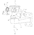
図1では、一実施形態によるカメラ機器のためのブラケット1が示される。図1には、ブラケットの特定の構成要素又は詳細は視覚化されておらず、図2の表示によって、図1に関する説明が明白になりうる。ブラケット1は、任意の適切な材料で作製され、例えば、ブラケット1に耐久性を与えかつ大量生産に適する適切な材料である、金属又はポリマー材で作製されうる。
In FIG. 1, a
ブラケット1は屋外又は屋内で使用される。ブラケット1は、ブラケットを、壁面又は他の適切な表面、或いは、例として柱、ポール、天井又は配管ボックスなどの物体に付設するために使用される壁掛け具2を有する。図1から図4に示す壁掛け具2は、ブラケット1の平面状表面への取付に適する。ブラケット1の非平面状表面への取付は、適切な改造により実現される。代替的には、非平面状表面への取付に関して、壁掛け具は、非平面状表面に取り付けられる適切なアダプタに取り付けられる。かかるアダプタは、ブラケット1の壁掛け具2が取り付けられる平面状表面、及び、ブラケットが取り付けられるべき非平面状表面に適合した非平面状表面を有する。壁面などへの付設は、例えば、第1取付孔4を貫通するネジ又はボルトといった固定手段を用いて、適切に実現される。壁面などへの付設は遊離可能な付設であり、また、固定手段に代わる、或いは追加的な付設が、例えば接着又は溶接によって行われる。アーム6は壁掛け具2から延在し、調整可能なカメラ架台8を支持する。任意の適切な種類のカメラ機器(図示せず)が、カメラ架台8に取り付けられる。カメラ機器により、任意の適切な監視用カメラ、及び/又はカメラハウジングが意図されている。アーム6は更に、カメラと壁掛け具2の間に間隔を設け、それにより、例えばカメラへの調整がより容易になり、カメラのパンとチルトの自由度が高まる。
The
カメラ架台8は、枢軸機構10を用いてチルト及びパンにより調整可能であり、カメラ機器が所望の位置に調整されると、その位置を係止するために係止要素22、24、26(図1には示していないが図2には示す)が使用される。枢軸機構10は、アーム6内に設けられたソケット20を備え、かかるソケット内には、第1部材12が載置されて、パン軸50の周囲を回転可能なパン継手40を形成する。ゆえに、カメラ架台8上に取り付けられたカメラ機器のパンが可能になる。図1から分かるように、第1部材12は、少なくとも部分的に、カメラ架台8と一体的に形成された第2部材14を囲む。第1部材と第2部材は共に、チルト軸52の周囲を回転可能なチルト継手42を形成する。パン軸50及びチルト軸52は、図3に図示されていることに留意されたい。ゆえに、カメラ架台8上に取り付けられたカメラのチルトが可能になる。壁面などに付設されたブラケット上に取り付けられた時、カメラ機器は、係止要素が非係止状態であれば、チルト軸52の周囲をチルトすること、及び、パン軸50の周囲をパンすることにより調整されうる。明確に定義された2つの軸を有し、かかる軸を中心とする動作を実現することは、それが予想可能な動作をもたらすという利点となる。カメラ架台は、パン軸50とチルト軸52以外の軸を中心とする、カメラ架台の動作を限定し又は防止するが、このことは例えば、不確定な数の軸を中心とする動作を可能にすることによって、動作に予測不可能性を導入する玉継手を有することに勝る利点である。
The
この実施形態により、カメラ架台8は取付平面を有しており、チルト軸52は取付平面に平行に延在し、パン軸50はチルト軸52に直交する。取付平面は、この実施例では、カメラ架台8の上端部を含む平面によって定義されうる。
According to this embodiment, the
実施形態により、カメラ架台は取付平面を有しており、チルト軸52は取付平面に平行に延在し、パン軸50はチルト軸52に直交し、チルト軸52が水平になるようにブラケットが取り付けられる限り、水平方向に並んだ複数の画像が実現しうることが理解されよう。
According to the embodiment, the camera mount has a mounting plane, the
チルト継手42とパン継手40をそれぞれ用いてチルトとパンを可能にすることは、パンとチルトが別個の作動として行われ、例えばパン動作の最中に不測のチルトが生じるリスクが低減し、逆もまた真であることから、有益である。更に、効率的な水平パン動作が可能になる。 Enabling tilt and pan using the tilt joint 42 and pan joint 40, respectively, allows panning and tilting to be performed as separate operations, for example, reducing the risk of inadvertent tilting during panning and vice versa. Is also beneficial because it is also true. Furthermore, an efficient horizontal pan operation is possible.
カメラ架台8は、例えば、カメラ架台の第2取付孔5を貫通するネジ又はボルトなどを用いて、カメラ機器を取り付けるよう配設される。カメラ架台8は、図1から図4に図示するように、平面を備える。代替的には、カメラ架台は、第2部材の上部にある孔部として実現可能であり、ネジを受容することが可能であり、或いは、カメラ又はカメラハウジングが取り付けられる第2部材の上部にネジが付設されうる。
The
係止要素26、22、24(図1には図示せず)は、カメラ架台を調整済位置に係止するために使用される。係止要素は更に、図2を参照して説明される。
Locking
ゆえに、図1に示すブラケット1は、カメラを係止位置、及び、カメラ機器による監視が所望される種々の状況における、商業施設、住居、又は公園或いは街路といった公共区域の監視などの監視目的に適する位置に、効率的に保持しうる。
Therefore, the
図2には、図1のブラケットの分解図が示されており、更に、図1を参照して説明された実施形態が明白に例示されている。図2より、この実施形態による枢軸機構の第1部材12は、2つの部品12’及び12”で作られることが分かる。ブラケット1の一部、2つの部品12’と12”は、取り付けられた時、第2部材14の少なくとも一部を囲む。第1部材12はキャップ形状部16を有する。この実施例では、2つの部品12’と12”の小区分16’及び16”は共にキャップ形状部16を形成する。キャップ形状部16は、相補的な形状のソケット20の台座部18内に載置されるよう配設される。
FIG. 2 shows an exploded view of the bracket of FIG. 1 and clearly illustrates the embodiment described with reference to FIG. From FIG. 2 it can be seen that the
図2には、係止要素26の実施例が示されている。この実施例による係止要素は、ネジ22及びナット24を有する。ネジ22は、取り付けられた時、開口部を通過してアーム6の下面を貫通し、ソケット20に至り、更に、第1部材12の底部に回転しない様態で取り付けられたナット24に至る。かかる係止要素を、第1部材12のテーパリング又は例えば半球形状と共に有することで、係止要素が、この実施例ではネジ22を締め付けることなどによって係止状態になると、第1部材12をソケットの台座部18に押圧することによってパン継手の位置を係止し、それに加えて、チルト継手の位置を係止するために第1部材12に囲まれた第2部材14上で作用する係止力を生成する。この実施例及び実施形態により、係止部材22、24を係止状態にすることは、ネジ22を締め付けることで、第1部材がソケット20に押圧されるようにすることによって行われる。図2に例示される実施形態では、第1部材12は、第1部材12と第2部材14の間の係止状態を改善するための、中央から径方向に延在する歯部30を有する。図2には図示されていないが、第2部材14は歯部、又は、歯部30と相補的な溝或いは凹所を有してもよい。ブラケットは、これらの歯部30及び/又は溝なしで機能してもよい。第1部材12は更に、取り付けられた時、ソケット内に延在することによって、第1部材12のパン動作を可能にするがチルト動作を防止する凸部32を有する。第1部材12及び第2部材14によって形成されたチルト継手42は、チルト軸52の周囲を回転可能であり、この実施形態により、シャフト36及び軸受38機構を備えることによって、係止機構が係止状態ではない時に、カメラ架台8のチルト動作が可能になる。係止機構が係止状態の時には、チルト動作は防止されることになる。
In FIG. 2, an embodiment of the locking
第1部材12のキャップ形状部16は歯部、例えばパン軸から径方向に延在する歯部を有し、ソケット20の台座部18は歯部、又はキャップ形状部の歯部と相補的な溝或いは凹所を有することができる。ゆえに、第1部材12とソケット20の間の係止状態の改善が実現する。ブラケットは、これらの歯部30及び/又は溝なしで機能することもできる。
The cap-shaped
この実施例では、チルト継手はシャフト36及び軸受38機構を有する。シャフト36は、図2では第2部材14の一方の側からのみ視認可能であるが、第2部材14の他方の側にもシャフト36がある。更に、図2では視認できないが、第1部材12の部品12”は、軸受38を有してもよい。シャフト36は代替的に第1部材12上に配設されてもよく、軸受38が第2部材14上に配設されてもよい。更に、チルト継手42は、例えば、第2部材14を囲む第1部材の相応形状部に組み合わされた円筒形状の第2部材によって、シャフト及び軸受機構なしでも機能しうることに留意されたい。別の実施形態により、シャフトは、チルト軸52に沿って第1部材12を貫通し、第2部材を貫通して延在するように設けられる。
In this embodiment, the tilt joint has a
係止要素26を完全には締め付けないことで、例えばチルトによる調整がパンによる調整から独立して行われるように、第1部材とソケットの間、及び、第1部材と第2部材の間に適切な摩擦がもたらされる。
By not completely tightening the locking
図2に図示されている実施形態により、第1部材のキャップ形状部16は、取り付けられた時、ソケットの底に向かってテーパされた円錐台形状になることに留意されたい。かかる形状は、パン継手の効率的な係止とチルト継手の効率的な係止の両方を提供する。係止要素26を係止状態にすることにより、第1部材12のキャップ形状部16は、ソケットの台座部18に効率的に押圧されることになり、チルト継手の位置を係止するための、第1部材を囲む第2部材上で作用する効率的な係止力が生成される。
It should be noted that, according to the embodiment illustrated in FIG. 2, the
壁掛け具、アーム及びカメラ架台は、カメラ機器へのケーブルをブラケットの内部に取り付けることを可能にするための空洞部を備えてもよい。一実施形態により、また、図2に示されているように、ブラケットは更に、第1部材のソケットに対するパン動作を限定することによって、ケーブルが第1部材とアームの間に挟まれて損傷を受けることを防止するパン止め70を含む。パン動作は、例えば190度に限定される。図2では、パン止め70は、第1部材12の第1凹所71として図示されている。パン止め70は更に、ソケット20内に第1部材12の第1凹所71と相互作用する凸部を備える。
The wall hanger, arm, and camera mount may include a cavity to allow a cable to the camera device to be attached to the interior of the bracket. According to one embodiment, and as shown in FIG. 2, the bracket further limits the panning action of the first member relative to the socket so that the cable can be pinched between the first member and the arm and damaged. It includes a
一実施形態により、キャップ形状部は、ソケットの底に向かう方向にテーパされうる。 According to one embodiment, the cap shape may be tapered in a direction toward the bottom of the socket.
第1部材のキャップ形状部16は、円錐台形に成形され、テーパされた形状であり、半球形状であり、或いは、円錐形状である。
The cap-shaped
ソケットの台座は、円錐台形に成形され、テーパされた形状であり、半球形状であり、或いは、円錐形状である。 The socket base is shaped into a truncated cone and has a tapered shape, a hemispherical shape, or a conical shape.
一実施形態により、係止機構26はネジ22及びナット24を備える。ナット24は、第1部材12の底部に埋設されることがある。ナットは、例えば図5に示されるように、第1部材12内のナットと相補的な形状を有する第2凹所80内に配設される。係止機構26は、目的に適した任意の種類のものであり、例えば、係止機構26は代替的に、第1部材12に付設されて配設されたネジ、及び、アームに当接してネジに締め付けられるよう配設されたナットと共に配設される。
According to one embodiment, the
係止要素は代替的にネジを備え、第1部材は、ネジと相補的なネジ山を有する凹所又は開口を備えることがある。かかる事例ではナットは必要ではない。 The locking element may alternatively comprise a screw and the first member may comprise a recess or opening having a thread complementary to the screw. In such cases, a nut is not necessary.
係止要素は代替的に、第1部材12の底部に付設され、ソケット及びアームを通過してアームの外側に係止される要素を備えうる。この係止要素は例えば、急速係止解除串型要素でありうる。
The locking element can alternatively comprise an element attached to the bottom of the
図3と図4は、図1及び図2にそれぞれ示した、ブラケット1の正面図及び側面図を示す。パン軸50とチルト軸52のおおよその位置が、点線とクロス円によって図3及び図4に図示されている。
3 and 4 show a front view and a side view of the
図5と図6は、ブラケットが壁面に取り付けられている時に、通常上側から見たブラケット1、及び、通常下側から見たブラケット1をそれぞれ示す。パン軸50とチルト軸52のおおよその位置が、点線とクロス円によって図3及び図4に図示されている。図3から図6に示すこの実施形態により、チルト軸52とパン軸50は直交していること、及び、チルト軸はカメラ架台8の取付平面9に平行であることに留意されたい。
5 and 6 show the
1 ブラケット
2 壁掛け具
4 第1取付孔
5 第2取付孔
6 アーム
8 カメラ架台
9 取付平面
10 枢軸機構
12 第1部材
14 第2部材
16 キャップ形状部
18 台座
20 ソケット
22 係止要素
24 係止要素
26 係止要素
30 歯部
32 凸部
36 シャフト
38 軸受
40 パン継手
42 チルト継手
50 パン軸
52 チルト軸
70 パン止め
71 第1凹所
80 第2凹所
DESCRIPTION OF
Claims (11)
壁掛け具(2)と、
前記壁掛け具(2)から延在するアーム(6)と、
前記アーム(6)によって支持されたカメラ架台(8)と、
前記カメラ架台(8)を調整済の角度位置に係止するための係止要素(22、24、26)とを備え、前記カメラ架台(8)の角度位置は、
前記アーム(6)内に設けられたソケット(20)と、
前記ソケット(20)内に載置され、各々にテーパ部分を有する2つの部材(12’、12”)で構成された第1部材(12)と、
組み立てられた状態では、前記第1部材(12)の前記2つの部材(12’、12”)で挟まれるとともに囲まれ、前記カメラ架台(8)と一体的に形成された第2部材(14)とを備えた、枢軸機構(10)を用いてチルト及びパンにより調整可能であり、
前記ソケット(20)と前記第1部材(12)は、パン軸(50)の周囲を回転可能なパン継手(40)を形成し、
前記第1部材(12)と前記第2部材(14)は、チルト軸(52)の周囲を回転可能なチルト継手(42)を形成し、
前記係止要素(22、24、26)は、前記第2部材(14)に取り付けられた第1のねじ部材(24)と、前記ソケット(20)に取り付けられた第2のねじ部材(22)とを有し、作動されたときに、前記第1のねじ部材(24)と前記第2のねじ部材(22)との係合量が増すことによって、前記第1部材(12)の前記テーパ部分の作用により、前記第1部材(12)を前記ソケット(20)に押圧して、前記パン軸(50)の周囲の前記パン継手(40)の角度位置を係止し、同時に、前記第1部材(12)に囲まれた前記第2部材(14)を拘束して前記チルト軸(52)の周囲の前記チルト継手(42)の角度位置を係止するよう配設されている、ブラケット(1)。 Bracket (1) for camera equipment,
Wall hangings (2),
An arm (6) extending from the wall hanging tool (2);
A camera mount (8) supported by the arm (6);
A locking element (22, 24, 26) for locking the camera mount (8) at the adjusted angular position, the angular position of the camera mount (8) being:
A socket (20) provided in the arm (6);
A first member (12) composed of two members (12 ′, 12 ″) mounted in the socket (20) and each having a tapered portion ;
In the assembled state, the first member (12) is sandwiched and surrounded by the two members (12 ′, 12 ″), and the second member (14) formed integrally with the camera mount (8). And can be adjusted by tilt and pan using a pivot mechanism (10),
The socket (20) and the first member (12) form a pan joint (40) rotatable around a pan shaft (50),
The first member (12) and the second member (14) form a tilt joint (42) rotatable around a tilt shaft (52),
The locking element (22, 24, 26) includes a first screw member (24) attached to the second member (14) and a second screw member (22) attached to the socket (20). ) and a, when activated, by the engagement of the first threaded member (24) and said second threaded member (22) increases, said first member (12) By the action of the taper portion, the first member (12) is pressed against the socket (20), and the angular position of the pan joint (40) around the pan shaft (50) is locked. The second member (14) surrounded by the first member (12) is constrained so as to lock the angular position of the tilt joint (42) around the tilt shaft (52). Bracket (1).
請求項1から10のいずれか一項に記載の前記ブラケット(1)、及び、前記ブラケット(1)によって支持されたカメラを備える、カメラシステム。 A camera system,
A camera system comprising the bracket (1) according to any one of claims 1 to 10 and a camera supported by the bracket (1).
Applications Claiming Priority (2)
| Application Number | Priority Date | Filing Date | Title |
|---|---|---|---|
| EP13193657.7A EP2876349B1 (en) | 2013-11-20 | 2013-11-20 | Mounting bracket |
| EP13193657.7 | 2013-11-20 |
Publications (3)
| Publication Number | Publication Date |
|---|---|
| JP2015108822A JP2015108822A (en) | 2015-06-11 |
| JP2015108822A5 JP2015108822A5 (en) | 2015-09-10 |
| JP5993429B2 true JP5993429B2 (en) | 2016-09-14 |
Family
ID=49641568
Family Applications (1)
| Application Number | Title | Priority Date | Filing Date |
|---|---|---|---|
| JP2014226768A Active JP5993429B2 (en) | 2013-11-20 | 2014-11-07 | Mounting bracket |
Country Status (6)
| Country | Link |
|---|---|
| US (1) | US9057934B2 (en) |
| EP (1) | EP2876349B1 (en) |
| JP (1) | JP5993429B2 (en) |
| KR (1) | KR101564400B1 (en) |
| CN (1) | CN104653988B (en) |
| TW (1) | TWI640711B (en) |
Cited By (1)
| Publication number | Priority date | Publication date | Assignee | Title |
|---|---|---|---|---|
| KR102078694B1 (en) * | 2019-01-28 | 2020-04-07 | 최재완 | Wall Mount Bracket for Factory Lamp |
Families Citing this family (27)
| Publication number | Priority date | Publication date | Assignee | Title |
|---|---|---|---|---|
| GB201507321D0 (en) * | 2015-04-29 | 2015-06-10 | Tom Tom Int Bv | Camera mounting |
| US9309012B1 (en) | 2015-06-13 | 2016-04-12 | Google Inc. | Method of packaging camera facilitating ease of installation |
| US9388934B1 (en) | 2015-06-13 | 2016-07-12 | Google Inc. | Camera stand having constant resistance for a portion of a range of motion along an axis of rotation |
| US9377157B1 (en) * | 2015-06-13 | 2016-06-28 | Google Inc. | Camera stand having an unlimited range of motion along an axis of rotation |
| KR200481843Y1 (en) * | 2016-04-06 | 2016-11-16 | 주식회사 에스에이치비젼 | Apparatus For Installation Of CCTV Camera |
| EP3246615B1 (en) * | 2016-05-20 | 2018-05-02 | Axis AB | A mounting assembly |
| CN105872494B (en) * | 2016-06-12 | 2019-03-08 | 深圳市创维群欣安防科技股份有限公司 | A kind of fright display screen |
| NL2016954B1 (en) * | 2016-06-13 | 2017-12-21 | Vlaar Innovations B V | Monitor arm coupling unit for coupling a flat panel display monitor to an end of a monitor arm of a monitor arm stand, and monitor arm stand including such a monitor coupling unit |
| GB201614739D0 (en) * | 2016-08-31 | 2016-10-12 | Tomtom Int Bv | A mount for portable electronic devices |
| US10388133B1 (en) | 2018-02-26 | 2019-08-20 | Panasonic Intellectual Property Management Co., Ltd. | Surveillance camera |
| JP6418434B1 (en) * | 2018-02-26 | 2018-11-07 | パナソニックIpマネジメント株式会社 | Surveillance camera |
| JP6418433B1 (en) * | 2018-02-26 | 2018-11-07 | パナソニックIpマネジメント株式会社 | Surveillance camera |
| KR101941161B1 (en) * | 2018-09-05 | 2019-01-22 | 주식회사 에이스타하이테크 | The bracket for cammera |
| USD902279S1 (en) * | 2018-09-21 | 2020-11-17 | VIDEOTECH S.p.A. | Video camera |
| EP3646840A1 (en) * | 2018-11-05 | 2020-05-06 | Ondal Medical Systems GmbH | Supply device for providing at least one supplying product |
| EP3739384B1 (en) * | 2019-05-17 | 2021-03-17 | Axis AB | A mount for an image capturing device |
| CN112492259B (en) * | 2019-09-12 | 2023-07-04 | 杭州海康威视数字技术股份有限公司 | Monitoring equipment and monitoring method |
| USD886183S1 (en) * | 2020-02-04 | 2020-06-02 | Isaac Fried | Camera mount |
| USD885471S1 (en) * | 2020-02-04 | 2020-05-26 | Isaac Fried | Camera mount |
| TWI770513B (en) * | 2020-05-20 | 2022-07-11 | 環進企業股份有限公司 | bracket |
| USD899488S1 (en) | 2020-06-10 | 2020-10-20 | Isaac Fried | Double camera mount |
| USD899490S1 (en) | 2020-06-10 | 2020-10-20 | Isaac Fried | Single camera mount |
| USD899489S1 (en) | 2020-06-10 | 2020-10-20 | Isaac Fried | Double camera mount |
| CN111795288B (en) * | 2020-07-27 | 2022-04-29 | 东莞市里鹏模具开发有限公司 | Adjusting bracket |
| KR102386451B1 (en) * | 2020-11-10 | 2022-04-14 | 이노디지털(주) | a device to measure air quality of visual information-linked type |
| US11513427B2 (en) | 2021-02-16 | 2022-11-29 | CKnapp Sales, Inc. | Methods and apparatus to mount a camera to a mounting device |
| KR20240032721A (en) * | 2021-07-08 | 2024-03-12 | 한화비전 주식회사 | Electronic mounting assembly |
Family Cites Families (15)
| Publication number | Priority date | Publication date | Assignee | Title |
|---|---|---|---|---|
| FI77105C (en) * | 1986-07-09 | 1989-01-10 | Nokia Oy Ab | STATIV SPECIELLT FOER BILDSKAERMSTERMINALER. |
| JP3202052B2 (en) * | 1992-01-10 | 2001-08-27 | 松下電器産業株式会社 | Camera mount |
| US5845885A (en) * | 1993-12-14 | 1998-12-08 | National Products, Inc. | Universally positionable mounting device |
| US5790910A (en) * | 1997-08-04 | 1998-08-04 | Peerless Industries, Inc. | Camera mounting apparatus |
| IT1302104B1 (en) | 1998-10-02 | 2000-07-20 | Videotec S R L | WALL SUPPORT FOR CAMERA HOUSING. |
| US6634804B1 (en) * | 2002-11-15 | 2003-10-21 | Pelco | Camera enclosure wall mount |
| US7334956B2 (en) * | 2003-06-20 | 2008-02-26 | Taylor Steve B | Coupler |
| JP4445322B2 (en) * | 2004-05-07 | 2010-04-07 | パナソニック株式会社 | Camera mounting device |
| GB2420702B (en) | 2005-12-03 | 2007-04-04 | Ason Cctv Industry Co Ltd | Support bracket for camera housing system |
| TWM315289U (en) * | 2007-01-29 | 2007-07-11 | Tsai Jung Cast Co Ltd | Supporting frame for multi-functional monitor |
| JP2010204381A (en) * | 2009-03-03 | 2010-09-16 | Sony Corp | Camera support device |
| CN201391724Y (en) * | 2009-04-24 | 2010-01-27 | 东莞顺传五金制品有限公司 | Monitor support frame |
| JP4989678B2 (en) * | 2009-05-19 | 2012-08-01 | ティーオーエー株式会社 | Camera fixtures and equipment fixtures |
| US8366060B2 (en) * | 2010-06-24 | 2013-02-05 | Modernsolid Industrial Co., Ltd. | Supporting arm assembly for a display |
| US8714860B2 (en) * | 2011-08-05 | 2014-05-06 | Cutsforth, Inc. | Mounting fixture including an articulation joint |
-
2013
- 2013-11-20 EP EP13193657.7A patent/EP2876349B1/en active Active
-
2014
- 2014-10-16 US US14/515,815 patent/US9057934B2/en active Active
- 2014-10-24 TW TW103136863A patent/TWI640711B/en active
- 2014-11-07 JP JP2014226768A patent/JP5993429B2/en active Active
- 2014-11-07 CN CN201410643907.XA patent/CN104653988B/en active Active
- 2014-11-20 KR KR1020140162939A patent/KR101564400B1/en active IP Right Grant
Cited By (1)
| Publication number | Priority date | Publication date | Assignee | Title |
|---|---|---|---|---|
| KR102078694B1 (en) * | 2019-01-28 | 2020-04-07 | 최재완 | Wall Mount Bracket for Factory Lamp |
Also Published As
| Publication number | Publication date |
|---|---|
| TW201520459A (en) | 2015-06-01 |
| CN104653988B (en) | 2016-05-04 |
| KR20150058090A (en) | 2015-05-28 |
| TWI640711B (en) | 2018-11-11 |
| KR101564400B1 (en) | 2015-10-30 |
| US9057934B2 (en) | 2015-06-16 |
| CN104653988A (en) | 2015-05-27 |
| EP2876349A1 (en) | 2015-05-27 |
| JP2015108822A (en) | 2015-06-11 |
| US20150139635A1 (en) | 2015-05-21 |
| EP2876349B1 (en) | 2015-08-12 |
Similar Documents
| Publication | Publication Date | Title |
|---|---|---|
| JP5993429B2 (en) | Mounting bracket | |
| JP2015108822A5 (en) | ||
| KR102005977B1 (en) | A surveillance camera device for intelligent defense boundary | |
| AU2015101592A4 (en) | Magnetic Universal Mounting Assembly | |
| US20070152116A1 (en) | Ball head | |
| EP3220036A1 (en) | A ball joint | |
| US20080008467A1 (en) | Omni-directional surveillance network video camera | |
| JP2011029831A5 (en) | ||
| WO2017165920A1 (en) | Multi-directional mounting bracket | |
| KR101369735B1 (en) | Pan/tilt ball type camera | |
| CN108737697B (en) | Camera casing device | |
| CN203322676U (en) | Surveillance camera support and surveillance camera device | |
| KR101405413B1 (en) | Multi bracket for cctv installation | |
| WO2021208891A1 (en) | Fixing device | |
| CN112136320B (en) | Three-axis dome type monitoring camera | |
| JP4989678B2 (en) | Camera fixtures and equipment fixtures | |
| KR101613314B1 (en) | housing braket for | |
| KR101518434B1 (en) | supporter for portable phone | |
| WO2016011272A2 (en) | Selectively orientable static bearing assembly | |
| JP2012094970A (en) | Television camera device | |
| JP2021099396A (en) | Swivel part fall prevention tool for swivel camera device, and swivel camera device | |
| KR101436356B1 (en) | Fixing device for CCTV | |
| JP2023108568A (en) | Surveillance camera | |
| KR20120001086U (en) | Angle control device increased turn-angle | |
| JP3059996U (en) | Monitoring device |
Legal Events
| Date | Code | Title | Description |
|---|---|---|---|
| A521 | Request for written amendment filed |
Free format text: JAPANESE INTERMEDIATE CODE: A523 Effective date: 20150723 |
|
| A621 | Written request for application examination |
Free format text: JAPANESE INTERMEDIATE CODE: A621 Effective date: 20150723 |
|
| A871 | Explanation of circumstances concerning accelerated examination |
Free format text: JAPANESE INTERMEDIATE CODE: A871 Effective date: 20150723 |
|
| A975 | Report on accelerated examination |
Free format text: JAPANESE INTERMEDIATE CODE: A971005 Effective date: 20151019 |
|
| A131 | Notification of reasons for refusal |
Free format text: JAPANESE INTERMEDIATE CODE: A131 Effective date: 20151027 |
|
| A521 | Request for written amendment filed |
Free format text: JAPANESE INTERMEDIATE CODE: A523 Effective date: 20160114 |
|
| A131 | Notification of reasons for refusal |
Free format text: JAPANESE INTERMEDIATE CODE: A131 Effective date: 20160329 |
|
| A521 | Request for written amendment filed |
Free format text: JAPANESE INTERMEDIATE CODE: A523 Effective date: 20160620 |
|
| TRDD | Decision of grant or rejection written | ||
| A01 | Written decision to grant a patent or to grant a registration (utility model) |
Free format text: JAPANESE INTERMEDIATE CODE: A01 Effective date: 20160809 |
|
| A61 | First payment of annual fees (during grant procedure) |
Free format text: JAPANESE INTERMEDIATE CODE: A61 Effective date: 20160819 |
|
| R150 | Certificate of patent or registration of utility model |
Ref document number: 5993429 Country of ref document: JP Free format text: JAPANESE INTERMEDIATE CODE: R150 |
|
| R250 | Receipt of annual fees |
Free format text: JAPANESE INTERMEDIATE CODE: R250 |
|
| R250 | Receipt of annual fees |
Free format text: JAPANESE INTERMEDIATE CODE: R250 |
|
| R250 | Receipt of annual fees |
Free format text: JAPANESE INTERMEDIATE CODE: R250 |
|
| R250 | Receipt of annual fees |
Free format text: JAPANESE INTERMEDIATE CODE: R250 |
|
| R250 | Receipt of annual fees |
Free format text: JAPANESE INTERMEDIATE CODE: R250 |