EP2876349B1 - Mounting bracket - Google Patents
Mounting bracket Download PDFInfo
- Publication number
- EP2876349B1 EP2876349B1 EP13193657.7A EP13193657A EP2876349B1 EP 2876349 B1 EP2876349 B1 EP 2876349B1 EP 13193657 A EP13193657 A EP 13193657A EP 2876349 B1 EP2876349 B1 EP 2876349B1
- Authority
- EP
- European Patent Office
- Prior art keywords
- bracket
- socket
- camera
- mount
- locking
- Prior art date
- Legal status (The legal status is an assumption and is not a legal conclusion. Google has not performed a legal analysis and makes no representation as to the accuracy of the status listed.)
- Active
Links
- 238000004091 panning Methods 0.000 claims description 19
- 230000004913 activation Effects 0.000 claims description 6
- 230000000295 complement effect Effects 0.000 claims description 4
- 230000008901 benefit Effects 0.000 description 5
- 238000012544 monitoring process Methods 0.000 description 5
- 239000000463 material Substances 0.000 description 2
- 230000006978 adaptation Effects 0.000 description 1
- 238000004026 adhesive bonding Methods 0.000 description 1
- 230000009286 beneficial effect Effects 0.000 description 1
- 230000001939 inductive effect Effects 0.000 description 1
- 238000004519 manufacturing process Methods 0.000 description 1
- 239000007769 metal material Substances 0.000 description 1
- 238000000034 method Methods 0.000 description 1
- 239000002861 polymer material Substances 0.000 description 1
- 238000003466 welding Methods 0.000 description 1
Images


Classifications
-
- H—ELECTRICITY
- H04—ELECTRIC COMMUNICATION TECHNIQUE
- H04N—PICTORIAL COMMUNICATION, e.g. TELEVISION
- H04N7/00—Television systems
- H04N7/18—Closed-circuit television [CCTV] systems, i.e. systems in which the video signal is not broadcast
-
- G—PHYSICS
- G03—PHOTOGRAPHY; CINEMATOGRAPHY; ANALOGOUS TECHNIQUES USING WAVES OTHER THAN OPTICAL WAVES; ELECTROGRAPHY; HOLOGRAPHY
- G03B—APPARATUS OR ARRANGEMENTS FOR TAKING PHOTOGRAPHS OR FOR PROJECTING OR VIEWING THEM; APPARATUS OR ARRANGEMENTS EMPLOYING ANALOGOUS TECHNIQUES USING WAVES OTHER THAN OPTICAL WAVES; ACCESSORIES THEREFOR
- G03B17/00—Details of cameras or camera bodies; Accessories therefor
- G03B17/56—Accessories
- G03B17/561—Support related camera accessories
-
- F—MECHANICAL ENGINEERING; LIGHTING; HEATING; WEAPONS; BLASTING
- F16—ENGINEERING ELEMENTS AND UNITS; GENERAL MEASURES FOR PRODUCING AND MAINTAINING EFFECTIVE FUNCTIONING OF MACHINES OR INSTALLATIONS; THERMAL INSULATION IN GENERAL
- F16M—FRAMES, CASINGS OR BEDS OF ENGINES, MACHINES OR APPARATUS, NOT SPECIFIC TO ENGINES, MACHINES OR APPARATUS PROVIDED FOR ELSEWHERE; STANDS; SUPPORTS
- F16M13/00—Other supports for positioning apparatus or articles; Means for steadying hand-held apparatus or articles
- F16M13/02—Other supports for positioning apparatus or articles; Means for steadying hand-held apparatus or articles for supporting on, or attaching to, an object, e.g. tree, gate, window-frame, cycle
-
- F—MECHANICAL ENGINEERING; LIGHTING; HEATING; WEAPONS; BLASTING
- F16—ENGINEERING ELEMENTS AND UNITS; GENERAL MEASURES FOR PRODUCING AND MAINTAINING EFFECTIVE FUNCTIONING OF MACHINES OR INSTALLATIONS; THERMAL INSULATION IN GENERAL
- F16M—FRAMES, CASINGS OR BEDS OF ENGINES, MACHINES OR APPARATUS, NOT SPECIFIC TO ENGINES, MACHINES OR APPARATUS PROVIDED FOR ELSEWHERE; STANDS; SUPPORTS
- F16M11/00—Stands or trestles as supports for apparatus or articles placed thereon ; Stands for scientific apparatus such as gravitational force meters
- F16M11/02—Heads
- F16M11/04—Means for attachment of apparatus; Means allowing adjustment of the apparatus relatively to the stand
- F16M11/06—Means for attachment of apparatus; Means allowing adjustment of the apparatus relatively to the stand allowing pivoting
- F16M11/10—Means for attachment of apparatus; Means allowing adjustment of the apparatus relatively to the stand allowing pivoting around a horizontal axis
-
- F—MECHANICAL ENGINEERING; LIGHTING; HEATING; WEAPONS; BLASTING
- F16—ENGINEERING ELEMENTS AND UNITS; GENERAL MEASURES FOR PRODUCING AND MAINTAINING EFFECTIVE FUNCTIONING OF MACHINES OR INSTALLATIONS; THERMAL INSULATION IN GENERAL
- F16M—FRAMES, CASINGS OR BEDS OF ENGINES, MACHINES OR APPARATUS, NOT SPECIFIC TO ENGINES, MACHINES OR APPARATUS PROVIDED FOR ELSEWHERE; STANDS; SUPPORTS
- F16M11/00—Stands or trestles as supports for apparatus or articles placed thereon ; Stands for scientific apparatus such as gravitational force meters
- F16M11/20—Undercarriages with or without wheels
- F16M11/2007—Undercarriages with or without wheels comprising means allowing pivoting adjustment
- F16M11/2014—Undercarriages with or without wheels comprising means allowing pivoting adjustment around a vertical axis
-
- H—ELECTRICITY
- H04—ELECTRIC COMMUNICATION TECHNIQUE
- H04N—PICTORIAL COMMUNICATION, e.g. TELEVISION
- H04N23/00—Cameras or camera modules comprising electronic image sensors; Control thereof
-
- H—ELECTRICITY
- H04—ELECTRIC COMMUNICATION TECHNIQUE
- H04N—PICTORIAL COMMUNICATION, e.g. TELEVISION
- H04N7/00—Television systems
- H04N7/18—Closed-circuit television [CCTV] systems, i.e. systems in which the video signal is not broadcast
- H04N7/188—Capturing isolated or intermittent images triggered by the occurrence of a predetermined event, e.g. an object reaching a predetermined position
Definitions
- the present invention relates to a bracket for a camera device and camera system.
- the camera may be mounted by means of a bracket on, for example, a wall of a building or a post.
- the document EP 0 990 833 discloses a camera bracket. Such a camera bracket may have problems with regard to weatherproofing and may be problematic to adjust and install.
- the cameras are stably mounted such that they are not unintentionally moved out of their adjusted positions for example by birds or force by weather. Further, it is desirable that the camera can be efficiently adjusted, thus providing the possibility to efficiently direct the camera in a desired direction.
- An object of the present invention is to provide an efficient bracket for a camera. Another object of the present invention is to provide solutions to problems related to prior art or improvements over prior art, which solutions or improvements may result in improved weatherproofing of the bracket and/or more efficient adjustment of a camera mounted on the bracket.
- a bracket for a camera device comprising a wall mount, an arm extending from the wall mount, an adjustable camera mount supported by the arm, and a locking element for locking of the camera mount in an adjusted position, the camera mount being adjustable by tilting and panning by means of a pivot arrangement.
- the pivot arrangement comprises a socket provided in the arm, a first member seated in the socket, and a second member, wherein the first member is formed in two pieces which in an assembled state are arranged to enclose the second member, wherein the second member is formed integral with said camera mount, wherein the socket and first member form a pan joint rotatable about a pan axis, and wherein the first member and the second member form a tilt joint rotatable about a tilt axis, and wherein the locking element upon activation is being arranged to press the first member against the socket in order to lock a position of the pan joint and to generate locking forces acting on the second member enclosed by the first member for locking of the position of the tilt joint.
- Having a pan joint and a tilt joint may provide for efficient adjustments, eg. since adjustments by tilting may be performed independently to adjustments by panning. Further, it is an advantage to have two well defined axes around which movements may be realized as it provides predictable movements.
- the camera mount limits or prevents movements of the camera mount around other axes than the pan and tilt axes which is an advantage over having for example a ball joint enabling movement around an undefined number of axes and thereby introducing an unpredictability in the movements.
- the camera mount being adjustable by tilting and panning by means of a pivot arrangement is efficient for adjustments of the viewing direction of a camera mounted to the camera mount.
- pivot arrangement comprising the first member seated in the socket, and the second member enclosed by the first member, enables a structure not having any openings exposing the interior of the bracket to the surroundings, thereby making it possible to provide a reliable weatherproofing.
- the camera mount may have a mount plane, wherein the tilt axis extends in parallel to the mount plane of the camera mount, and the pan axis is orthogonal to the tilt axis.
- the tilt axis extends in parallel to the mount plane of the camera mount, and the pan axis is orthogonal to the tilt axis.
- the locking element upon activation is arranged to press the first member against the socket in order to lock a position of the pan joint and to generate locking forces acting on the second member enclosed by the first member for locking of the position of the tilt
- the locking element may comprise a screw extending through a bottom of the socket, whereby the locking element is arranged for locking of the camera mount in an adjusted position by tightening of the screw causing the first member to be pressed against the socket.
- the first member may comprise a cap shaped section seated in the socket and a protrusion having an extension in the socket and cooperating therewith in order to prevent tilting of the first member relative to the socket.
- the seat of the socket may be frustoconically shaped. With such a frustoconical shape, efficient movement about the pan axis may be achieved. Further, with such a frustoconical shape, efficient locking of the camera mount in an adjusted position may be realized.
- the cap shaped section of the first member may be frustoconically shaped.
- efficient rotation about the pan axis may be achieved.
- efficient locking of the camera mount in an adjusted position may be realized, for example as the frustoconical shape may allow the first member to perform a squeezing action on the second member which is enclosed by the first member.
- the shape of the seat of the socket may be complementary to the shape of the cap shaped section of the first member.
- the protrusion may be cylindrically shaped and extending in a cylindrically shaped cavity of the socket.
- efficient rotation around the pan axis may be achieved.
- the protrusion may be circular-cylindrically shaped and extending in a complementary shaped cavity of the socket.
- the first member is formed in two pieces which in an assembled state are arranged to enclose the second member.
- assembling of the bracket may be efficient, and the first member may efficiently enclose the second member.
- locking forces acting on the second member enclosed by the first member may efficiently be achieved.
- the tilt joint may comprise a shaft and bearing arrangement.
- the wall mount, the arm, and the camera mount may comprise cavities for allowing of cables to a camera device to be fitted in the interior of the bracket.
- cables may extend from the wall plate to a camera device mounted on the camera mount.
- any cables to a camera device mounted on the bracket may be protected, such as from ambient conditions, weather, accidents or vandalism.
- a camera system comprising the bracket according to the first aspect of the present invention and a camera supported by the bracket.
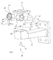
- bracket 1 for a camera device according to an embodiment is illustrated. Certain components or details of the bracket are not visualized in figure 1 and viewing of figure 2 may clarify the discussions related to figure 1 .
- the bracket 1 may be made of any suitable material and it may be made of, for example, metal or polymer material, which may be suitable materials providing endurance to the bracket 1 and being suitable for mass production.
- the bracket 1 may be used outdoors or indoors.
- the bracket 1 has a wall mount 2 which may be used for attachment of the bracket to a wall or other suitable surfaces or objects such as for example a post, a pole, a ceiling, or a conduit box.
- the wall mount 2 illustrated in figures 1 to 4 is suitable for mounting of the bracket 1 to a planar surface. It is realized that mounting of the bracket 1 to a non-planar surface may benefit from suitable adaptation. Alternatively, for mounting to non-planar surfaces, the wall mount may be mounted to a suitable adaptor, which is mounted to the non-planar surface.
- Such an adaptor may have a planar surface to which the wall mount 2 of the bracket 1 may be mounted and a non-planar surface adapted to the non-planar surface to which the bracket should be mounted.
- Attachment to eg. a wall may suitably be realized by means of fastening means, such as, for example, screws or bolts, through first mounting holes 4. It is realized that attachment to eg. a wall may be releasable attachment and that the attachment alternatively or in addition to fastening means may be made for example by gluing or welding.
- Extending from the wall mount 2 is an arm 6 providing support for an adjustable camera mount 8.
- To the camera mount 8 may be mounted any suitable type of camera device (not illustrated). By camera device, any suitable camera for monitoring and/or camera housing is intended.
- the arm 6 further provides distance between the camera and the wall mount 2 which may realize, for example, easier adjustments to the camera and improved freedom of panning and tilting of the camera.
- the camera mount 8 is adjustable by tilting and panning by means of a pivot arrangement 10, and a locking element 22, 24, 26 (not illustrated in figure 1 but illustrated in figure 2 ) is used for locking the position of the camera device once it is adjusted in a desired position.
- the pivot arrangement 10 comprises a socket 20 provided in the arm 6, in which socket a first member 12 is seated forming a pan joint 40 rotatable about a pan axis 50.
- the first member 12 at least partially encloses a second member 14 formed integral with the camera mount 8. Together, the first member and the second member form a tilt joint 42 rotatable about a tilt axis 52.
- pan axis 50 and a tilt axis 52 are indicated in figure 3 .
- the camera device When mounted on the bracket attached to eg. a wall, the camera device may be adjusted by tilting about the tilt axis 52 and panning about the pan axis 50, provided that the locking element is inactivated.
- the camera mount limits or prevents movements of the camera mount around other axes than the pan axis 50 and tilt axis 52 which is an advantage over having for example a ball joint enabling movement around an undefined number of axes and thereby introducing an unpredictability in the movements.
- the camera mount 8 is having a mount plane, wherein the tilt axis 52 extends in parallel to the mount plane and the pan axis 50 is orthogonal to the tilt axis 52.
- the mount plane in this example may be defined by the plane comprising the top edge of the camera mount 8. It will be understood that according to embodiments wherein the camera mount is having a mount plane wherein the tilt axis 52 extends in parallel to the mount plane and the pan axis 50 is orthogonal to the tilt axis 52, and provided that the bracket is mounted such that the tilt axis 52 is horizontal, horizontally aligned images may be realized.
- tilting and panning is made possible by means of the tilt joint 42 and the pan joint 40 respectively since panning and tilting thus may be made as separate actions, and the risk of, for example, unintentional tilting during panning movements are reduced and vice versa. Further, efficient horizontal pan movements are made possible.
- a locking element 26, 22, 24 may be activated for locking of the camera mount in an adjusted position.
- the locking element is further explained with reference to figure 2 .
- the bracket 1 illustrated in figure 1 thus efficiently may hold a camera in a locked position and a position suitable for monitoring purposes, such as monitoring of commercial establishments, homes, or public areas such as parks or streets, in different situations where monitoring by a camera device is desired.
- the first member 12 of the pivot arrangement may be made in two parts 12' and 12".
- the two parts 12' and 12" encloses at least a part of the second member 14.
- the first member 12 has a cap shaped section 16.
- subsections 16' and 16" of the two parts 12' and 12" together form the cap shaped section 16.
- the cap shaped section 16 is arranged to be seated in a complimentary shaped seat portion 18 of the socket 20.
- FIG 2 an example of the locking element 26 is illustrated.
- the locking element according to this example has a screw 22 and a nut 24.
- the screw 22 when mounted, is passing an opening through the bottom of the arm 6 into the socket 20, and further into the nut 24 fixed in a nonrotational manner at a bottom portion of first member 12.
- the locking element upon activation, such as in this example by tightening of the screw 22, will press the first member 12 against the seat portion 18 of the socket thereby locking the position of the pan joint and, in addition, generate locking forces acting on the second member 14 enclosed by the first member 12 for locking of the position of the tilt joint.
- the first member 12 has teeth 30 radially extending from a center for inducing improved locking between the first member 12 and the second member 14.
- the second member 14 may have teeth, or grooves or recesses complimentary to the teeth 30.
- the bracket may also be functioning without these teeth 30 and/or grooves.
- the first member 12 further has a protrusion 32 extending in the socket when mounted, thereby enabling a panning movement but preventing tilting of the first member 12.
- the tilt joint 42 formed by the first member 12 and the second member 14 is rotatable about a tilt axis 52 which according to this embodiment comprises a shaft 36 and bearing 38 arrangement thereby allowing a tilt movement of the camera mount 8 when the locking arrangement is not activated. When the locking arrangement is activated, tilting movements will be prevented.
- the tilt joint has a shaft 36 and bearing 38 arrangement.
- the shaft 36 is only visible on one side of the second member 14 in figure 2 , but it is realized that also the other side of the second member 14 may have a shaft 36.
- part 12" of the first member 12 may have a bearing 38, although not visible in figure 2 .
- the shaft 36 alternatively may be arranged on the first member 12 and the bearing 38 may be arranged on the second member 14.
- the tilt joint 42 may function without a shaft and bearing arrangement, for example by a circular cylindrical shape of the second member 14 combined with a correspondingly shaped section of the first member 12 enclosing the second member 14.
- a shaft may be provided extending along the tilt axis 52 through the first member 12 and through the second member.
- Partial tightening of the locking element 26 may provide suitable friction between first member and the socket, and between the first member and the second member, such that eg. adjustment by tilting may be made independently from adjustment by panning.
- the cap shaped section 16 of the first member 12 is of a frustoconical shape tapered towards the bottom of the socket when mounted. Such a shape, may provide both efficient locking of the pan joint and efficient locking of the tilt joint: By activation of the locking element 26 the cap shaped section 16 of the first member 12 will efficiently be pressed and locked against the seat portion 18 of the socket; and efficient locking forces acting on the second member enclosed by the first member for locking of the position of the tilt joint may be generated.
- the wall mount, the arm, and the camera mount may comprise cavities for allowing of cables to a camera device to be fitted in the interior of the bracket.
- the bracket may further include a panning stop 70, limiting the panning movement of the first member in relation to the socket and thereby preventing that the cables are clamped between the first member and the arm and thereby damaged.
- the panning movement may be limited to, for example, 190 degrees.
- the panning stop 70 is illustrated as a first recess 71 of the first member 12.
- the panning stop 70 further comprises a protrusion in the socket 20 interacting with the first recess 71 of the first member 12.
- the cap shaped section may be tapered in a direction towards a bottom the socket.
- the cap shaped section 16 of the first member may be frustoconically shaped, of tapered shape, semi spherically shaped, or conically shaped.
- the seat of the socket may be frustoconically shaped, of tapered shape, semi spherically shaped, or conically shaped.
- the locking arrangement 26 may comprise a screw 22 and a nut 24.
- the nut 24 may be embedded in a bottom portion of the first member 12.
- the nut may be arranged in the first member 12 in a second recess 80 with a complimentary shape to the nut, for example as illustrated in figure 5 .
- the locking arrangement 26 may be of any type suitable for the purpose, for example the locking arrangement 26 may alternatively be arranged with a screw arranged attached to the first member 12 and a nut arranged to be tightened on the screw against the arm.
- the locking element may alternatively comprise a screw, and the first member may comprise a recess or aperture with threads complimentary to the screw. In such a case, no nut is needed.
- the locking element may alternatively comprise an element that is attached to the bottom portion of the first member 12 and proceeds through the socket and arm, and locked on the outside of the arm.
- the locking element may, for example, be of a quick release skewer type.
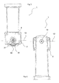
- Figures 3 and 4 illustrates front and side views of the bracket 1 illustrated in figures 1 and 2 , respectively. Approximate positions of the pan axis 50 and tilt axis 52 are indicated in figures 3 and 4 by dotted lines and a crossed circle.
- FIGs 5 and 6 illustrates the bracket 1 as normally seen from above and as normally seen from below when the bracket is mounted on a wall, respectively. Approximate positions of the pan axis 50 and tilt axis 52 are indicated in figures 3 and 4 by dotted lines and a crossed circle. Note that according to this embodiment as illustrated by figures 3 to 6 , the tilt axis 52 and the pan axis 50 are orthogonal and that the tilt axis is parallel to a mount plane 9 of the camera mount 8.
Landscapes
- Engineering & Computer Science (AREA)
- General Engineering & Computer Science (AREA)
- Mechanical Engineering (AREA)
- Multimedia (AREA)
- Signal Processing (AREA)
- Physics & Mathematics (AREA)
- General Physics & Mathematics (AREA)
- Accessories Of Cameras (AREA)
- Studio Devices (AREA)
Description
- The present invention relates to a bracket for a camera device and camera system.
- Cameras for monitoring of scenes frequently exist in various environments such as interiors and exteriors of shops, homes, and in outdoor environments such as streets, parking lots and parks. For such and other purposes the camera may be mounted by means of a bracket on, for example, a wall of a building or a post.
- The document
EP 0 990 833 discloses a camera bracket. Such a camera bracket may have problems with regard to weatherproofing and may be problematic to adjust and install. - The document
US 4,770,382 discloses a stand for adjusting the viewing angle of a display terminal. - It is desirable that the cameras are stably mounted such that they are not unintentionally moved out of their adjusted positions for example by birds or force by weather. Further, it is desirable that the camera can be efficiently adjusted, thus providing the possibility to efficiently direct the camera in a desired direction.
- An object of the present invention is to provide an efficient bracket for a camera. Another object of the present invention is to provide solutions to problems related to prior art or improvements over prior art, which solutions or improvements may result in improved weatherproofing of the bracket and/or more efficient adjustment of a camera mounted on the bracket.
- According to a first aspect of the invention, which is defined by the
independent claim 1, those and other objects are achieved by a bracket for a camera device comprising a wall mount, an arm extending from the wall mount, an adjustable camera mount supported by the arm, and a locking element for locking of the camera mount in an adjusted position, the camera mount being adjustable by tilting and panning by means of a pivot arrangement. The pivot arrangement comprises a socket provided in the arm, a first member seated in the socket, and a second member,
wherein the first member is formed in two pieces which in an assembled state are arranged to enclose the second member,
wherein the second member is formed integral with said camera mount, wherein the socket and first member form a pan joint rotatable about a pan axis, and wherein the first member and the second member form a tilt joint rotatable about a tilt axis, and wherein the locking element upon activation is being arranged to press the first member against the socket in order to lock a position of the pan joint and to generate locking forces acting on the second member enclosed by the first member for locking of the position of the tilt joint. - Having a pan joint and a tilt joint may provide for efficient adjustments, eg. since adjustments by tilting may be performed independently to adjustments by panning. Further, it is an advantage to have two well defined axes around which movements may be realized as it provides predictable movements. The camera mount limits or prevents movements of the camera mount around other axes than the pan and tilt axes which is an advantage over having for example a ball joint enabling movement around an undefined number of axes and thereby introducing an unpredictability in the movements.
- The camera mount being adjustable by tilting and panning by means of a pivot arrangement is efficient for adjustments of the viewing direction of a camera mounted to the camera mount..
- Further, the pivot arrangement comprising the first member seated in the socket, and the second member enclosed by the first member, enables a structure not having any openings exposing the interior of the bracket to the surroundings, thereby making it possible to provide a reliable weatherproofing.
- According to an embodiment, the camera mount may have a mount plane, wherein the tilt axis extends in parallel to the mount plane of the camera mount, and the pan axis is orthogonal to the tilt axis. Thus, for example, horizontally aligned images captured by a camera device mounted to the bracket may be realized.
- According to the present invention, the locking element upon activation is arranged to press the first member against the socket in order to lock a position of the pan joint and to generate locking forces acting on the second member enclosed by the first member for locking of the position of the tilt
- According to one embodiment, the locking element may comprise a screw extending through a bottom of the socket, whereby the locking element is arranged for locking of the camera mount in an adjusted position by tightening of the screw causing the first member to be pressed against the socket.
- According to one embodiment, the first member may comprise a cap shaped section seated in the socket and a protrusion having an extension in the socket and cooperating therewith in order to prevent tilting of the first member relative to the socket. Thus, efficient panning adjustments may be achieved by means of the pan joint, and efficient tilting adjustments may be achieved by means of the tilt joint.
- According to one embodiment, the seat of the socket may be frustoconically shaped. With such a frustoconical shape, efficient movement about the pan axis may be achieved. Further, with such a frustoconical shape, efficient locking of the camera mount in an adjusted position may be realized.
- According to one embodiment, the cap shaped section of the first member may be frustoconically shaped. Thus, efficient rotation about the pan axis may be achieved. Further, with such a frustoconical shape, efficient locking of the camera mount in an adjusted position may be realized, for example as the frustoconical shape may allow the first member to perform a squeezing action on the second member which is enclosed by the first member.
- According to one embodiment, the shape of the seat of the socket may be complementary to the shape of the cap shaped section of the first member.
- According to one embodiment, the protrusion may be cylindrically shaped and extending in a cylindrically shaped cavity of the socket. Thus, efficient rotation around the pan axis may be achieved.
- According to one embodiment, the protrusion may be circular-cylindrically shaped and extending in a complementary shaped cavity of the socket.
- According to the present invention, the first member is formed in two pieces which in an assembled state are arranged to enclose the second member. With the first member formed in two pieces, assembling of the bracket may be efficient, and the first member may efficiently enclose the second member. Further, locking forces acting on the second member enclosed by the first member may efficiently be achieved.
- According to one embodiment, the tilt joint may comprise a shaft and bearing arrangement.
- According to one embodiment, the wall mount, the arm, and the camera mount may comprise cavities for allowing of cables to a camera device to be fitted in the interior of the bracket. Thus, cables may extend from the wall plate to a camera device mounted on the camera mount. Thus, any cables to a camera device mounted on the bracket may be protected, such as from ambient conditions, weather, accidents or vandalism.
- According to another aspect of the present invention there is provided a camera system comprising the bracket according to the first aspect of the present invention and a camera supported by the bracket.
- Generally, all terms used in the claims are to be interpreted according to their ordinary meaning in the technical field, unless explicitly defined otherwise herein. All references to "a/an/the [element, device, component, means, step, etc.] are to be interpreted openly as referring to at least one instance of said element, device component, means, step, etc., unless explicitly stated otherwise. The steps of any method disclosed herein do not have to be performed in the exact order disclosed, unless explicitly stated.
-
-
Fig. 1 illustrates a bracket for a camera according to an embodiment. -
Fig. 2 is an exploded view of the bracket for a camera according to the embodiment illustrated infigure 1 . -
Fig. 3 is a front view of the bracket for a camera according to the embodiment illustrated infigure 1 , as seen along the arm of the bracket in a direction towards the wall mount. -
Fig. 4 is a side view of the bracket for a camera according to the embodiment illustrated infigure 1 . -
Fig. 5 is a top view of the bracket for a camera according to the embodiment illustrated infigure 1 . -
Fig. 6 is a bottom view of the bracket for a camera according to the embodiment illustrated infigure 1 . - The present invention will now be described in more detail with reference to the accompanying drawings, in which embodiments of the invention are shown. The invention may, however, be embodied in many different forms and should not be construed as limited to the embodiments of this detailed description which are provided for thoroughness and completeness of the invention.
- In
figure 1 abracket 1 for a camera device according to an embodiment is illustrated. Certain components or details of the bracket are not visualized infigure 1 and viewing offigure 2 may clarify the discussions related tofigure 1 . Thebracket 1 may be made of any suitable material and it may be made of, for example, metal or polymer material, which may be suitable materials providing endurance to thebracket 1 and being suitable for mass production. - The
bracket 1 may be used outdoors or indoors. Thebracket 1 has awall mount 2 which may be used for attachment of the bracket to a wall or other suitable surfaces or objects such as for example a post, a pole, a ceiling, or a conduit box. Thewall mount 2 illustrated infigures 1 to 4 is suitable for mounting of thebracket 1 to a planar surface. It is realized that mounting of thebracket 1 to a non-planar surface may benefit from suitable adaptation. Alternatively, for mounting to non-planar surfaces, the wall mount may be mounted to a suitable adaptor, which is mounted to the non-planar surface. Such an adaptor may have a planar surface to which thewall mount 2 of thebracket 1 may be mounted and a non-planar surface adapted to the non-planar surface to which the bracket should be mounted. Attachment to eg. a wall may suitably be realized by means of fastening means, such as, for example, screws or bolts, through first mounting holes 4. It is realized that attachment to eg. a wall may be releasable attachment and that the attachment alternatively or in addition to fastening means may be made for example by gluing or welding. Extending from thewall mount 2 is anarm 6 providing support for anadjustable camera mount 8. To thecamera mount 8 may be mounted any suitable type of camera device (not illustrated). By camera device, any suitable camera for monitoring and/or camera housing is intended. It is realized that thearm 6 further provides distance between the camera and thewall mount 2 which may realize, for example, easier adjustments to the camera and improved freedom of panning and tilting of the camera. - The
camera mount 8 is adjustable by tilting and panning by means of apivot arrangement 10, and a lockingelement figure 1 but illustrated infigure 2 ) is used for locking the position of the camera device once it is adjusted in a desired position. Thepivot arrangement 10 comprises asocket 20 provided in thearm 6, in which socket afirst member 12 is seated forming a pan joint 40 rotatable about apan axis 50. Thus panning of a camera device mounted on thecamera mount 8 is made possible. As seen infigure 1 , thefirst member 12 at least partially encloses asecond member 14 formed integral with thecamera mount 8. Together, the first member and the second member form a tilt joint 42 rotatable about atilt axis 52. Note that thepan axis 50 and atilt axis 52 are indicated infigure 3 . Thus, tilting of a camera mounted on thecamera mount 8 is made possible. When mounted on the bracket attached to eg. a wall, the camera device may be adjusted by tilting about thetilt axis 52 and panning about thepan axis 50, provided that the locking element is inactivated. It is an advantage to have two well defined axes around which movements may be realized as it provides predictable movements. The camera mount limits or prevents movements of the camera mount around other axes than thepan axis 50 andtilt axis 52 which is an advantage over having for example a ball joint enabling movement around an undefined number of axes and thereby introducing an unpredictability in the movements. - According to this example, the
camera mount 8 is having a mount plane, wherein thetilt axis 52 extends in parallel to the mount plane and thepan axis 50 is orthogonal to thetilt axis 52. The mount plane in this example may be defined by the plane comprising the top edge of thecamera mount 8. It will be understood that according to embodiments wherein the camera mount is having a mount plane wherein thetilt axis 52 extends in parallel to the mount plane and thepan axis 50 is orthogonal to thetilt axis 52, and provided that the bracket is mounted such that thetilt axis 52 is horizontal, horizontally aligned images may be realized. - It is beneficial that tilting and panning is made possible by means of the tilt joint 42 and the pan joint 40 respectively since panning and tilting thus may be made as separate actions, and the risk of, for example, unintentional tilting during panning movements are reduced and vice versa. Further, efficient horizontal pan movements are made possible.
- The
camera mount 8 is arranged for mounting of the camera device, such as, for example, by means of screws or bolts through second mountingholes 5 of the camera mount. Thecamera mount 8 may comprise a plate as is depicted infigures 1 to 4 . Alternatively the camera mount may be realized as a hole in the top portion of the second member, able to receive a screw, or a screw attached to the top portion of the second member, to which a camera or a camera housing may be mounted. - A locking
element figure 1 ) may be activated for locking of the camera mount in an adjusted position. The locking element is further explained with reference tofigure 2 . - The
bracket 1 illustrated infigure 1 , thus efficiently may hold a camera in a locked position and a position suitable for monitoring purposes, such as monitoring of commercial establishments, homes, or public areas such as parks or streets, in different situations where monitoring by a camera device is desired. - Turning to
figure 2 , an exploded view of the bracket ofFigure 1 is illustrated, further clarifying and exemplifying the embodiment discussed with reference tofigure 1 . Fromfigure 2 , it is realized that thefirst member 12 of the pivot arrangement according to this embodiment may be made in twoparts 12' and 12". When mounted and part of thebracket 1, the twoparts 12' and 12" encloses at least a part of thesecond member 14. Thefirst member 12 has a cap shapedsection 16. In this example,subsections 16' and 16" of the twoparts 12' and 12" together form the cap shapedsection 16. The cap shapedsection 16 is arranged to be seated in a complimentary shapedseat portion 18 of thesocket 20. - In
figure 2 , an example of the lockingelement 26 is illustrated. The locking element according to this example has ascrew 22 and anut 24. Thescrew 22, when mounted, is passing an opening through the bottom of thearm 6 into thesocket 20, and further into thenut 24 fixed in a nonrotational manner at a bottom portion offirst member 12. It is realized that with such a locking element, in combination with the tapering, or for example a semi spherical shape, of thefirst member 12, the locking element upon activation, such as in this example by tightening of thescrew 22, will press thefirst member 12 against theseat portion 18 of the socket thereby locking the position of the pan joint and, in addition, generate locking forces acting on thesecond member 14 enclosed by thefirst member 12 for locking of the position of the tilt joint. Activation of the lockingmember screw 22, thereby causing the first member to be pressed against thesocket 20. In the embodiment exemplified byfigure 2 , thefirst member 12 hasteeth 30 radially extending from a center for inducing improved locking between thefirst member 12 and thesecond member 14. Although not illustrated infigure 2 , thesecond member 14 may have teeth, or grooves or recesses complimentary to theteeth 30. The bracket may also be functioning without theseteeth 30 and/or grooves. Thefirst member 12 further has aprotrusion 32 extending in the socket when mounted, thereby enabling a panning movement but preventing tilting of thefirst member 12. The tilt joint 42 formed by thefirst member 12 and thesecond member 14 is rotatable about atilt axis 52 which according to this embodiment comprises ashaft 36 and bearing 38 arrangement thereby allowing a tilt movement of thecamera mount 8 when the locking arrangement is not activated. When the locking arrangement is activated, tilting movements will be prevented. - The cap shaped
section 16 of thefirst member 12 may have teeth, for example teeth radially extending from the pan axis, and theseat portion 18 of thesocket 20 may have teeth, or or grooves or recesses complimentary to the teeth of the cap shaped section. Thus, improved locking between thefirst member 12 and thesocket 20 may be realized. The bracket may also be functioning without theseteeth 30 and/or grooves. - In this example, the tilt joint has a
shaft 36 and bearing 38 arrangement. Theshaft 36 is only visible on one side of thesecond member 14 infigure 2 , but it is realized that also the other side of thesecond member 14 may have ashaft 36. Further,part 12" of thefirst member 12 may have abearing 38, although not visible infigure 2 . It is realized that theshaft 36 alternatively may be arranged on thefirst member 12 and thebearing 38 may be arranged on thesecond member 14. It is further noted that the tilt joint 42 may function without a shaft and bearing arrangement, for example by a circular cylindrical shape of thesecond member 14 combined with a correspondingly shaped section of thefirst member 12 enclosing thesecond member 14. According to another embodiment, a shaft may be provided extending along thetilt axis 52 through thefirst member 12 and through the second member. - Partial tightening of the locking
element 26 may provide suitable friction between first member and the socket, and between the first member and the second member, such that eg. adjustment by tilting may be made independently from adjustment by panning. - It can be noted from
figure 2 that the cap shapedsection 16 of thefirst member 12 according to the illustrated embodiment is of a frustoconical shape tapered towards the bottom of the socket when mounted. Such a shape, may provide both efficient locking of the pan joint and efficient locking of the tilt joint: By activation of the lockingelement 26 the cap shapedsection 16 of thefirst member 12 will efficiently be pressed and locked against theseat portion 18 of the socket; and efficient locking forces acting on the second member enclosed by the first member for locking of the position of the tilt joint may be generated. - The wall mount, the arm, and the camera mount may comprise cavities for allowing of cables to a camera device to be fitted in the interior of the bracket. According to one embodiment and as illustrated by
figure 2 , the bracket may further include a panningstop 70, limiting the panning movement of the first member in relation to the socket and thereby preventing that the cables are clamped between the first member and the arm and thereby damaged. The panning movement may be limited to, for example, 190 degrees. Infigure 2 , the panningstop 70 is illustrated as afirst recess 71 of thefirst member 12. The panningstop 70 further comprises a protrusion in thesocket 20 interacting with thefirst recess 71 of thefirst member 12. - According to one embodiment, the cap shaped section may be tapered in a direction towards a bottom the socket.
- The cap shaped
section 16 of the first member may be frustoconically shaped, of tapered shape, semi spherically shaped, or conically shaped. - The seat of the socket may be frustoconically shaped, of tapered shape, semi spherically shaped, or conically shaped.
- According to one embodiment, the locking
arrangement 26 may comprise ascrew 22 and anut 24. Thenut 24 may be embedded in a bottom portion of thefirst member 12. The nut may be arranged in thefirst member 12 in asecond recess 80 with a complimentary shape to the nut, for example as illustrated infigure 5 . It is realized that the lockingarrangement 26 may be of any type suitable for the purpose, for example the lockingarrangement 26 may alternatively be arranged with a screw arranged attached to thefirst member 12 and a nut arranged to be tightened on the screw against the arm. - The locking element may alternatively comprise a screw, and the first member may comprise a recess or aperture with threads complimentary to the screw. In such a case, no nut is needed.
- The locking element may alternatively comprise an element that is attached to the bottom portion of the
first member 12 and proceeds through the socket and arm, and locked on the outside of the arm. The locking element may, for example, be of a quick release skewer type. -
Figures 3 and 4 illustrates front and side views of thebracket 1 illustrated infigures 1 and2 , respectively. Approximate positions of thepan axis 50 andtilt axis 52 are indicated infigures 3 and 4 by dotted lines and a crossed circle. -
Figures 5 and 6 illustrates thebracket 1 as normally seen from above and as normally seen from below when the bracket is mounted on a wall, respectively. Approximate positions of thepan axis 50 andtilt axis 52 are indicated infigures 3 and 4 by dotted lines and a crossed circle. Note that according to this embodiment as illustrated byfigures 3 to 6 , thetilt axis 52 and thepan axis 50 are orthogonal and that the tilt axis is parallel to amount plane 9 of thecamera mount 8.
Claims (11)
- Bracket (1) for a camera device, comprising
a wall mount (2),
an arm (6) extending from the wall mount (2),
an adjustable camera mount (8) supported by the arm (6), and
a locking element (22, 24, 26) for locking of the camera mount (8) in an adjusted position, the camera mount (8) being adjustable by tilting and panning by means of a pivot arrangement (10) comprising
a socket (20) provided in the arm (6), the bracket further comprising
a first member (12) seated in the socket (20), and a second member (14), and
wherein the second member (14) is formed integral with said camera mount (8),
wherein the socket (20) and first member (12) form a pan joint (40) rotatable about a pan axis (50),
wherein the first member (12) and the second member (14) form a tilt joint (42) rotatable about a tilt axis (52), characterized in that
the first member (12) is formed in two pieces which in an assembled state are arranged to enclose the second member (14), and
wherein the locking element (22, 24, 26) upon activation is being arranged to press the first member (12) against the socket (20) in order to lock a position of the pan joint (40) and to generate locking forces acting on the second member (14) enclosed by the first member (12) for locking of the position of the tilt joint (42). - The bracket according to claim 1, wherein the camera mount (8) is having a mount plane (9), wherein the tilt axis (52) extends in parallel to the mount (9) plane of the camera mount, and the pan axis (50) is orthogonal to the tilt axis (52).
- The bracket (1) according to claim 1, wherein the locking element (22, 24, 26) comprises a screw extending through a bottom of the socket (20), whereby the locking element (22, 24, 26) is arranged for locking of the camera mount (8) in an adjusted position by tightening of the screw causing the first member (12) to be pressed against the socket (20).
- The bracket (1) according to anyone of the preceding claims, wherein the first member (12) comprises a cap shaped section (16) seated in the socket (20) and a protrusion (32) having an extension in the socket (20) and cooperating therewith in order to prevent tilting of the first member (12) relative to the socket (20).
- The bracket (1) according to claim 4, wherein the seat (18) of the socket (20) being frustoconically shaped.
- The bracket (1) according to claim 4 or 5, wherein the cap shaped section (16) of the first member (12) being frustoconically shaped.
- The bracket (1) according to anyone of claims 4 to 6, wherein the shape of the seat (18) of the socket (20) is complementary to the shape of the cap shaped section (16) of the first member (12).
- The bracket (1) according to anyone of claims 4 to 7, wherein the protrusion (32) being cylindrically shaped and extending in a complementary shaped cavity of the socket (20).
- The bracket (1) according to anyone of the preceding claims, wherein the tilt joint (42) comprises a shaft (36) and bearing (38) arrangement.
- The bracket (1) according to anyone of the preceding claims, wherein the wall mount (2), the arm (6), and the camera mount (8) comprise cavities for allowing of cables to a camera to be fitted in the interior of the bracket (1).
- Camera system comprising
the bracket (1) according to anyone of claims 1 to 10, and a camera supported by the bracket (1).
Priority Applications (6)
| Application Number | Priority Date | Filing Date | Title |
|---|---|---|---|
| EP13193657.7A EP2876349B1 (en) | 2013-11-20 | 2013-11-20 | Mounting bracket |
| US14/515,815 US9057934B2 (en) | 2013-11-20 | 2014-10-16 | Mounting bracket |
| TW103136863A TWI640711B (en) | 2013-11-20 | 2014-10-24 | Bracket for a camera device and carmera system |
| JP2014226768A JP5993429B2 (en) | 2013-11-20 | 2014-11-07 | Mounting bracket |
| CN201410643907.XA CN104653988B (en) | 2013-11-20 | 2014-11-07 | For bracket and the camera system of camera head |
| KR1020140162939A KR101564400B1 (en) | 2013-11-20 | 2014-11-20 | Mounting bracket |
Applications Claiming Priority (1)
| Application Number | Priority Date | Filing Date | Title |
|---|---|---|---|
| EP13193657.7A EP2876349B1 (en) | 2013-11-20 | 2013-11-20 | Mounting bracket |
Publications (2)
| Publication Number | Publication Date |
|---|---|
| EP2876349A1 EP2876349A1 (en) | 2015-05-27 |
| EP2876349B1 true EP2876349B1 (en) | 2015-08-12 |
Family
ID=49641568
Family Applications (1)
| Application Number | Title | Priority Date | Filing Date |
|---|---|---|---|
| EP13193657.7A Active EP2876349B1 (en) | 2013-11-20 | 2013-11-20 | Mounting bracket |
Country Status (6)
| Country | Link |
|---|---|
| US (1) | US9057934B2 (en) |
| EP (1) | EP2876349B1 (en) |
| JP (1) | JP5993429B2 (en) |
| KR (1) | KR101564400B1 (en) |
| CN (1) | CN104653988B (en) |
| TW (1) | TWI640711B (en) |
Families Citing this family (28)
| Publication number | Priority date | Publication date | Assignee | Title |
|---|---|---|---|---|
| GB201507321D0 (en) * | 2015-04-29 | 2015-06-10 | Tom Tom Int Bv | Camera mounting |
| US9309012B1 (en) | 2015-06-13 | 2016-04-12 | Google Inc. | Method of packaging camera facilitating ease of installation |
| US9388934B1 (en) | 2015-06-13 | 2016-07-12 | Google Inc. | Camera stand having constant resistance for a portion of a range of motion along an axis of rotation |
| US9377157B1 (en) | 2015-06-13 | 2016-06-28 | Google Inc. | Camera stand having an unlimited range of motion along an axis of rotation |
| KR200481843Y1 (en) * | 2016-04-06 | 2016-11-16 | 주식회사 에스에이치비젼 | Apparatus For Installation Of CCTV Camera |
| EP3246615B1 (en) * | 2016-05-20 | 2018-05-02 | Axis AB | A mounting assembly |
| CN105872494B (en) * | 2016-06-12 | 2019-03-08 | 深圳市创维群欣安防科技股份有限公司 | A kind of fright display screen |
| NL2016954B1 (en) * | 2016-06-13 | 2017-12-21 | Vlaar Innovations B V | Monitor arm coupling unit for coupling a flat panel display monitor to an end of a monitor arm of a monitor arm stand, and monitor arm stand including such a monitor coupling unit |
| GB201614739D0 (en) * | 2016-08-31 | 2016-10-12 | Tomtom Int Bv | A mount for portable electronic devices |
| JP6418434B1 (en) * | 2018-02-26 | 2018-11-07 | パナソニックIpマネジメント株式会社 | Surveillance camera |
| US10388133B1 (en) | 2018-02-26 | 2019-08-20 | Panasonic Intellectual Property Management Co., Ltd. | Surveillance camera |
| JP6418433B1 (en) * | 2018-02-26 | 2018-11-07 | パナソニックIpマネジメント株式会社 | Surveillance camera |
| KR101941161B1 (en) * | 2018-09-05 | 2019-01-22 | 주식회사 에이스타하이테크 | The bracket for cammera |
| USD902280S1 (en) * | 2018-09-21 | 2020-11-17 | Videotec S.P.A. | Video camera |
| EP3646840A1 (en) * | 2018-11-05 | 2020-05-06 | Ondal Medical Systems GmbH | Supply device for providing at least one supplying product |
| KR102078694B1 (en) * | 2019-01-28 | 2020-04-07 | 최재완 | Wall Mount Bracket for Factory Lamp |
| EP3739384B1 (en) * | 2019-05-17 | 2021-03-17 | Axis AB | A mount for an image capturing device |
| CN112492259B (en) * | 2019-09-12 | 2023-07-04 | 杭州海康威视数字技术股份有限公司 | Monitoring equipment and monitoring method |
| USD885471S1 (en) | 2020-02-04 | 2020-05-26 | Isaac Fried | Camera mount |
| USD886183S1 (en) | 2020-02-04 | 2020-06-02 | Isaac Fried | Camera mount |
| TWI770513B (en) * | 2020-05-20 | 2022-07-11 | 環進企業股份有限公司 | bracket |
| USD899490S1 (en) | 2020-06-10 | 2020-10-20 | Isaac Fried | Single camera mount |
| USD899489S1 (en) | 2020-06-10 | 2020-10-20 | Isaac Fried | Double camera mount |
| USD899488S1 (en) | 2020-06-10 | 2020-10-20 | Isaac Fried | Double camera mount |
| CN111795288B (en) * | 2020-07-27 | 2022-04-29 | 东莞市里鹏模具开发有限公司 | Adjusting bracket |
| KR102386451B1 (en) * | 2020-11-10 | 2022-04-14 | 이노디지털(주) | a device to measure air quality of visual information-linked type |
| US11513427B2 (en) | 2021-02-16 | 2022-11-29 | CKnapp Sales, Inc. | Methods and apparatus to mount a camera to a mounting device |
| EP4369094A1 (en) * | 2021-07-08 | 2024-05-15 | Hanwha Vision Co., Ltd. | Electronic equipment mounting assembly |
Family Cites Families (15)
| Publication number | Priority date | Publication date | Assignee | Title |
|---|---|---|---|---|
| FI77105C (en) * | 1986-07-09 | 1989-01-10 | Nokia Oy Ab | STATIV SPECIELLT FOER BILDSKAERMSTERMINALER. |
| JP3202052B2 (en) * | 1992-01-10 | 2001-08-27 | 松下電器産業株式会社 | Camera mount |
| US5845885A (en) * | 1993-12-14 | 1998-12-08 | National Products, Inc. | Universally positionable mounting device |
| US5790910A (en) * | 1997-08-04 | 1998-08-04 | Peerless Industries, Inc. | Camera mounting apparatus |
| IT1302104B1 (en) | 1998-10-02 | 2000-07-20 | Videotec S R L | WALL SUPPORT FOR CAMERA HOUSING. |
| US6634804B1 (en) * | 2002-11-15 | 2003-10-21 | Pelco | Camera enclosure wall mount |
| US7334956B2 (en) * | 2003-06-20 | 2008-02-26 | Taylor Steve B | Coupler |
| JP4445322B2 (en) * | 2004-05-07 | 2010-04-07 | パナソニック株式会社 | Camera mounting device |
| GB2420702B (en) | 2005-12-03 | 2007-04-04 | Ason Cctv Industry Co Ltd | Support bracket for camera housing system |
| TWM315289U (en) * | 2007-01-29 | 2007-07-11 | Tsai Jung Cast Co Ltd | Supporting frame for multi-functional monitor |
| JP2010204381A (en) * | 2009-03-03 | 2010-09-16 | Sony Corp | Camera support device |
| CN201391724Y (en) * | 2009-04-24 | 2010-01-27 | 东莞顺传五金制品有限公司 | Monitor support frame |
| JP4989678B2 (en) * | 2009-05-19 | 2012-08-01 | ティーオーエー株式会社 | Camera fixtures and equipment fixtures |
| US8366060B2 (en) * | 2010-06-24 | 2013-02-05 | Modernsolid Industrial Co., Ltd. | Supporting arm assembly for a display |
| US8714860B2 (en) * | 2011-08-05 | 2014-05-06 | Cutsforth, Inc. | Mounting fixture including an articulation joint |
-
2013
- 2013-11-20 EP EP13193657.7A patent/EP2876349B1/en active Active
-
2014
- 2014-10-16 US US14/515,815 patent/US9057934B2/en active Active
- 2014-10-24 TW TW103136863A patent/TWI640711B/en active
- 2014-11-07 CN CN201410643907.XA patent/CN104653988B/en active Active
- 2014-11-07 JP JP2014226768A patent/JP5993429B2/en active Active
- 2014-11-20 KR KR1020140162939A patent/KR101564400B1/en active IP Right Grant
Also Published As
| Publication number | Publication date |
|---|---|
| KR20150058090A (en) | 2015-05-28 |
| US9057934B2 (en) | 2015-06-16 |
| JP5993429B2 (en) | 2016-09-14 |
| US20150139635A1 (en) | 2015-05-21 |
| TW201520459A (en) | 2015-06-01 |
| CN104653988B (en) | 2016-05-04 |
| KR101564400B1 (en) | 2015-10-30 |
| TWI640711B (en) | 2018-11-11 |
| EP2876349A1 (en) | 2015-05-27 |
| JP2015108822A (en) | 2015-06-11 |
| CN104653988A (en) | 2015-05-27 |
Similar Documents
| Publication | Publication Date | Title |
|---|---|---|
| EP2876349B1 (en) | Mounting bracket | |
| US9690172B2 (en) | Omnidirectional user configurable multi-camera housing | |
| US20200084413A1 (en) | Intelligent defense surveillance camera device | |
| US9952485B1 (en) | Video surveillance camera having a separable and removable gimbal | |
| AU2013204513B2 (en) | A camera | |
| KR100724306B1 (en) | Bracket for Closed-Circuit Television | |
| US20160086461A1 (en) | Surveillance camera having integrated assembly features | |
| US20070165137A1 (en) | Supporting frame for CCTV camera enclosure | |
| US20190113072A1 (en) | Multi-Directional Mounting Bracket | |
| EP3562140B1 (en) | Two axis pan tilt camera system configured to maintain a level image when wall or ceiling mounted | |
| US20030103161A1 (en) | Reduce size structure of surveillance camera | |
| EP3181983B1 (en) | An arrangement for supporting a monitoring camera and a method for assembling the arrangement | |
| US20070253702A1 (en) | Security surveillance system and method of operating same | |
| AU2008221519A1 (en) | Mounting bracket | |
| KR200419680Y1 (en) | Controler for angular motion and length of the camera for CCTV | |
| JP4989678B2 (en) | Camera fixtures and equipment fixtures | |
| JP6713179B1 (en) | Accessories for mobile devices | |
| CN112136320B (en) | Three-axis dome type monitoring camera | |
| KR20210028983A (en) | Cradle of Car Room Mirror Monitor | |
| JP2010082421A (en) | Mirror attaching device | |
| JP3059996U (en) | Monitoring device | |
| JP2023108568A (en) | Surveillance camera | |
| CN113606460A (en) | Installation supporting device | |
| CA2631805A1 (en) | Twist-lock canting mount for surveillance cameras | |
| KR101436356B1 (en) | Fixing device for CCTV |
Legal Events
| Date | Code | Title | Description |
|---|---|---|---|
| GRAP | Despatch of communication of intention to grant a patent |
Free format text: ORIGINAL CODE: EPIDOSNIGR1 |
|
| GRAP | Despatch of communication of intention to grant a patent |
Free format text: ORIGINAL CODE: EPIDOSNIGR1 |
|
| PUAI | Public reference made under article 153(3) epc to a published international application that has entered the european phase |
Free format text: ORIGINAL CODE: 0009012 |
|
| 17P | Request for examination filed |
Effective date: 20140926 |
|
| AK | Designated contracting states |
Kind code of ref document: A1 Designated state(s): AL AT BE BG CH CY CZ DE DK EE ES FI FR GB GR HR HU IE IS IT LI LT LU LV MC MK MT NL NO PL PT RO RS SE SI SK SM TR |
|
| AX | Request for extension of the european patent |
Extension state: BA ME |
|
| GRAS | Grant fee paid |
Free format text: ORIGINAL CODE: EPIDOSNIGR3 |
|
| GRAA | (expected) grant |
Free format text: ORIGINAL CODE: 0009210 |
|
| AK | Designated contracting states |
Kind code of ref document: B1 Designated state(s): AL AT BE BG CH CY CZ DE DK EE ES FI FR GB GR HR HU IE IS IT LI LT LU LV MC MK MT NL NO PL PT RO RS SE SI SK SM TR |
|
| REG | Reference to a national code |
Ref country code: GB Ref legal event code: FG4D |
|
| REG | Reference to a national code |
Ref country code: CH Ref legal event code: EP |
|
| REG | Reference to a national code |
Ref country code: AT Ref legal event code: REF Ref document number: 742484 Country of ref document: AT Kind code of ref document: T Effective date: 20150815 |
|
| REG | Reference to a national code |
Ref country code: SE Ref legal event code: TRGR |
|
| REG | Reference to a national code |
Ref country code: IE Ref legal event code: FG4D |
|
| REG | Reference to a national code |
Ref country code: DE Ref legal event code: R096 Ref document number: 602013002625 Country of ref document: DE |
|
| REG | Reference to a national code |
Ref country code: FR Ref legal event code: PLFP Year of fee payment: 3 |
|
| REG | Reference to a national code |
Ref country code: LT Ref legal event code: MG4D |
|
| REG | Reference to a national code |
Ref country code: AT Ref legal event code: MK05 Ref document number: 742484 Country of ref document: AT Kind code of ref document: T Effective date: 20150812 |
|
| REG | Reference to a national code |
Ref country code: NL Ref legal event code: MP Effective date: 20150812 |
|
| PG25 | Lapsed in a contracting state [announced via postgrant information from national office to epo] |
Ref country code: LT Free format text: LAPSE BECAUSE OF FAILURE TO SUBMIT A TRANSLATION OF THE DESCRIPTION OR TO PAY THE FEE WITHIN THE PRESCRIBED TIME-LIMIT Effective date: 20150812 Ref country code: LV Free format text: LAPSE BECAUSE OF FAILURE TO SUBMIT A TRANSLATION OF THE DESCRIPTION OR TO PAY THE FEE WITHIN THE PRESCRIBED TIME-LIMIT Effective date: 20150812 Ref country code: FI Free format text: LAPSE BECAUSE OF FAILURE TO SUBMIT A TRANSLATION OF THE DESCRIPTION OR TO PAY THE FEE WITHIN THE PRESCRIBED TIME-LIMIT Effective date: 20150812 Ref country code: NO Free format text: LAPSE BECAUSE OF FAILURE TO SUBMIT A TRANSLATION OF THE DESCRIPTION OR TO PAY THE FEE WITHIN THE PRESCRIBED TIME-LIMIT Effective date: 20151112 Ref country code: GR Free format text: LAPSE BECAUSE OF FAILURE TO SUBMIT A TRANSLATION OF THE DESCRIPTION OR TO PAY THE FEE WITHIN THE PRESCRIBED TIME-LIMIT Effective date: 20151113 |
|
| PG25 | Lapsed in a contracting state [announced via postgrant information from national office to epo] |
Ref country code: HR Free format text: LAPSE BECAUSE OF FAILURE TO SUBMIT A TRANSLATION OF THE DESCRIPTION OR TO PAY THE FEE WITHIN THE PRESCRIBED TIME-LIMIT Effective date: 20150812 Ref country code: PT Free format text: LAPSE BECAUSE OF FAILURE TO SUBMIT A TRANSLATION OF THE DESCRIPTION OR TO PAY THE FEE WITHIN THE PRESCRIBED TIME-LIMIT Effective date: 20151214 Ref country code: AT Free format text: LAPSE BECAUSE OF FAILURE TO SUBMIT A TRANSLATION OF THE DESCRIPTION OR TO PAY THE FEE WITHIN THE PRESCRIBED TIME-LIMIT Effective date: 20150812 Ref country code: ES Free format text: LAPSE BECAUSE OF FAILURE TO SUBMIT A TRANSLATION OF THE DESCRIPTION OR TO PAY THE FEE WITHIN THE PRESCRIBED TIME-LIMIT Effective date: 20150812 Ref country code: RS Free format text: LAPSE BECAUSE OF FAILURE TO SUBMIT A TRANSLATION OF THE DESCRIPTION OR TO PAY THE FEE WITHIN THE PRESCRIBED TIME-LIMIT Effective date: 20150812 Ref country code: PL Free format text: LAPSE BECAUSE OF FAILURE TO SUBMIT A TRANSLATION OF THE DESCRIPTION OR TO PAY THE FEE WITHIN THE PRESCRIBED TIME-LIMIT Effective date: 20150812 Ref country code: IS Free format text: LAPSE BECAUSE OF FAILURE TO SUBMIT A TRANSLATION OF THE DESCRIPTION OR TO PAY THE FEE WITHIN THE PRESCRIBED TIME-LIMIT Effective date: 20151212 |
|
| PG25 | Lapsed in a contracting state [announced via postgrant information from national office to epo] |
Ref country code: NL Free format text: LAPSE BECAUSE OF FAILURE TO SUBMIT A TRANSLATION OF THE DESCRIPTION OR TO PAY THE FEE WITHIN THE PRESCRIBED TIME-LIMIT Effective date: 20150812 |
|
| PG25 | Lapsed in a contracting state [announced via postgrant information from national office to epo] |
Ref country code: EE Free format text: LAPSE BECAUSE OF FAILURE TO SUBMIT A TRANSLATION OF THE DESCRIPTION OR TO PAY THE FEE WITHIN THE PRESCRIBED TIME-LIMIT Effective date: 20150812 Ref country code: IT Free format text: LAPSE BECAUSE OF FAILURE TO SUBMIT A TRANSLATION OF THE DESCRIPTION OR TO PAY THE FEE WITHIN THE PRESCRIBED TIME-LIMIT Effective date: 20150812 Ref country code: SK Free format text: LAPSE BECAUSE OF FAILURE TO SUBMIT A TRANSLATION OF THE DESCRIPTION OR TO PAY THE FEE WITHIN THE PRESCRIBED TIME-LIMIT Effective date: 20150812 Ref country code: DK Free format text: LAPSE BECAUSE OF FAILURE TO SUBMIT A TRANSLATION OF THE DESCRIPTION OR TO PAY THE FEE WITHIN THE PRESCRIBED TIME-LIMIT Effective date: 20150812 Ref country code: CZ Free format text: LAPSE BECAUSE OF FAILURE TO SUBMIT A TRANSLATION OF THE DESCRIPTION OR TO PAY THE FEE WITHIN THE PRESCRIBED TIME-LIMIT Effective date: 20150812 |
|
| REG | Reference to a national code |
Ref country code: DE Ref legal event code: R097 Ref document number: 602013002625 Country of ref document: DE |
|
| PG25 | Lapsed in a contracting state [announced via postgrant information from national office to epo] |
Ref country code: RO Free format text: LAPSE BECAUSE OF FAILURE TO SUBMIT A TRANSLATION OF THE DESCRIPTION OR TO PAY THE FEE WITHIN THE PRESCRIBED TIME-LIMIT Effective date: 20150812 |
|
| PLBE | No opposition filed within time limit |
Free format text: ORIGINAL CODE: 0009261 |
|
| STAA | Information on the status of an ep patent application or granted ep patent |
Free format text: STATUS: NO OPPOSITION FILED WITHIN TIME LIMIT |
|
| PG25 | Lapsed in a contracting state [announced via postgrant information from national office to epo] |
Ref country code: LU Free format text: LAPSE BECAUSE OF FAILURE TO SUBMIT A TRANSLATION OF THE DESCRIPTION OR TO PAY THE FEE WITHIN THE PRESCRIBED TIME-LIMIT Effective date: 20151120 Ref country code: MC Free format text: LAPSE BECAUSE OF FAILURE TO SUBMIT A TRANSLATION OF THE DESCRIPTION OR TO PAY THE FEE WITHIN THE PRESCRIBED TIME-LIMIT Effective date: 20150812 |
|
| 26N | No opposition filed |
Effective date: 20160513 |
|
| REG | Reference to a national code |
Ref country code: IE Ref legal event code: MM4A |
|
| PG25 | Lapsed in a contracting state [announced via postgrant information from national office to epo] |
Ref country code: SI Free format text: LAPSE BECAUSE OF FAILURE TO SUBMIT A TRANSLATION OF THE DESCRIPTION OR TO PAY THE FEE WITHIN THE PRESCRIBED TIME-LIMIT Effective date: 20150812 |
|
| REG | Reference to a national code |
Ref country code: FR Ref legal event code: PLFP Year of fee payment: 4 |
|
| PG25 | Lapsed in a contracting state [announced via postgrant information from national office to epo] |
Ref country code: IE Free format text: LAPSE BECAUSE OF NON-PAYMENT OF DUE FEES Effective date: 20151120 |
|
| PG25 | Lapsed in a contracting state [announced via postgrant information from national office to epo] |
Ref country code: BE Free format text: LAPSE BECAUSE OF FAILURE TO SUBMIT A TRANSLATION OF THE DESCRIPTION OR TO PAY THE FEE WITHIN THE PRESCRIBED TIME-LIMIT Effective date: 20150812 |
|
| PG25 | Lapsed in a contracting state [announced via postgrant information from national office to epo] |
Ref country code: BG Free format text: LAPSE BECAUSE OF FAILURE TO SUBMIT A TRANSLATION OF THE DESCRIPTION OR TO PAY THE FEE WITHIN THE PRESCRIBED TIME-LIMIT Effective date: 20150812 |
|
| PG25 | Lapsed in a contracting state [announced via postgrant information from national office to epo] |
Ref country code: HU Free format text: LAPSE BECAUSE OF FAILURE TO SUBMIT A TRANSLATION OF THE DESCRIPTION OR TO PAY THE FEE WITHIN THE PRESCRIBED TIME-LIMIT; INVALID AB INITIO Effective date: 20131120 Ref country code: CY Free format text: LAPSE BECAUSE OF FAILURE TO SUBMIT A TRANSLATION OF THE DESCRIPTION OR TO PAY THE FEE WITHIN THE PRESCRIBED TIME-LIMIT Effective date: 20150812 |
|
| REG | Reference to a national code |
Ref country code: CH Ref legal event code: PL |
|
| PG25 | Lapsed in a contracting state [announced via postgrant information from national office to epo] |
Ref country code: LI Free format text: LAPSE BECAUSE OF NON-PAYMENT OF DUE FEES Effective date: 20161130 Ref country code: CH Free format text: LAPSE BECAUSE OF NON-PAYMENT OF DUE FEES Effective date: 20161130 |
|
| PG25 | Lapsed in a contracting state [announced via postgrant information from national office to epo] |
Ref country code: MT Free format text: LAPSE BECAUSE OF FAILURE TO SUBMIT A TRANSLATION OF THE DESCRIPTION OR TO PAY THE FEE WITHIN THE PRESCRIBED TIME-LIMIT Effective date: 20150812 |
|
| REG | Reference to a national code |
Ref country code: FR Ref legal event code: PLFP Year of fee payment: 5 |
|
| PG25 | Lapsed in a contracting state [announced via postgrant information from national office to epo] |
Ref country code: SM Free format text: LAPSE BECAUSE OF FAILURE TO SUBMIT A TRANSLATION OF THE DESCRIPTION OR TO PAY THE FEE WITHIN THE PRESCRIBED TIME-LIMIT Effective date: 20150812 |
|
| PG25 | Lapsed in a contracting state [announced via postgrant information from national office to epo] |
Ref country code: MK Free format text: LAPSE BECAUSE OF FAILURE TO SUBMIT A TRANSLATION OF THE DESCRIPTION OR TO PAY THE FEE WITHIN THE PRESCRIBED TIME-LIMIT Effective date: 20150812 |
|
| REG | Reference to a national code |
Ref country code: FR Ref legal event code: PLFP Year of fee payment: 6 |
|
| PG25 | Lapsed in a contracting state [announced via postgrant information from national office to epo] |
Ref country code: AL Free format text: LAPSE BECAUSE OF FAILURE TO SUBMIT A TRANSLATION OF THE DESCRIPTION OR TO PAY THE FEE WITHIN THE PRESCRIBED TIME-LIMIT Effective date: 20150812 Ref country code: TR Free format text: LAPSE BECAUSE OF FAILURE TO SUBMIT A TRANSLATION OF THE DESCRIPTION OR TO PAY THE FEE WITHIN THE PRESCRIBED TIME-LIMIT Effective date: 20150812 |
|
| P01 | Opt-out of the competence of the unified patent court (upc) registered |
Effective date: 20230505 |
|
| PGFP | Annual fee paid to national office [announced via postgrant information from national office to epo] |
Ref country code: GB Payment date: 20231019 Year of fee payment: 11 |
|
| PGFP | Annual fee paid to national office [announced via postgrant information from national office to epo] |
Ref country code: SE Payment date: 20231020 Year of fee payment: 11 Ref country code: FR Payment date: 20231019 Year of fee payment: 11 Ref country code: DE Payment date: 20231019 Year of fee payment: 11 |