EP3646840A1 - Supply device for providing at least one supplying product - Google Patents
Supply device for providing at least one supplying product Download PDFInfo
- Publication number
- EP3646840A1 EP3646840A1 EP18204425.5A EP18204425A EP3646840A1 EP 3646840 A1 EP3646840 A1 EP 3646840A1 EP 18204425 A EP18204425 A EP 18204425A EP 3646840 A1 EP3646840 A1 EP 3646840A1
- Authority
- EP
- European Patent Office
- Prior art keywords
- cantilever arm
- connection
- pivot axis
- arm
- supply device
- Prior art date
- Legal status (The legal status is an assumption and is not a legal conclusion. Google has not performed a legal analysis and makes no representation as to the accuracy of the status listed.)
- Withdrawn
Links
Images


Classifications
-
- A—HUMAN NECESSITIES
- A61—MEDICAL OR VETERINARY SCIENCE; HYGIENE
- A61G—TRANSPORT, PERSONAL CONVEYANCES, OR ACCOMMODATION SPECIALLY ADAPTED FOR PATIENTS OR DISABLED PERSONS; OPERATING TABLES OR CHAIRS; CHAIRS FOR DENTISTRY; FUNERAL DEVICES
- A61G12/00—Accommodation for nursing, e.g. in hospitals, not covered by groups A61G1/00 - A61G11/00, e.g. trolleys for transport of medicaments or food; Prescription lists
- A61G12/002—Supply appliances, e.g. columns for gas, fluid, electricity supply
- A61G12/004—Supply appliances, e.g. columns for gas, fluid, electricity supply mounted on the ceiling
-
- A—HUMAN NECESSITIES
- A61—MEDICAL OR VETERINARY SCIENCE; HYGIENE
- A61G—TRANSPORT, PERSONAL CONVEYANCES, OR ACCOMMODATION SPECIALLY ADAPTED FOR PATIENTS OR DISABLED PERSONS; OPERATING TABLES OR CHAIRS; CHAIRS FOR DENTISTRY; FUNERAL DEVICES
- A61G12/00—Accommodation for nursing, e.g. in hospitals, not covered by groups A61G1/00 - A61G11/00, e.g. trolleys for transport of medicaments or food; Prescription lists
- A61G12/002—Supply appliances, e.g. columns for gas, fluid, electricity supply
- A61G12/005—Supply appliances, e.g. columns for gas, fluid, electricity supply mounted on the wall
-
- F—MECHANICAL ENGINEERING; LIGHTING; HEATING; WEAPONS; BLASTING
- F16—ENGINEERING ELEMENTS AND UNITS; GENERAL MEASURES FOR PRODUCING AND MAINTAINING EFFECTIVE FUNCTIONING OF MACHINES OR INSTALLATIONS; THERMAL INSULATION IN GENERAL
- F16M—FRAMES, CASINGS OR BEDS OF ENGINES, MACHINES OR APPARATUS, NOT SPECIFIC TO ENGINES, MACHINES OR APPARATUS PROVIDED FOR ELSEWHERE; STANDS; SUPPORTS
- F16M13/00—Other supports for positioning apparatus or articles; Means for steadying hand-held apparatus or articles
- F16M13/02—Other supports for positioning apparatus or articles; Means for steadying hand-held apparatus or articles for supporting on, or attaching to, an object, e.g. tree, gate, window-frame, cycle
- F16M13/027—Ceiling supports
-
- H—ELECTRICITY
- H01—ELECTRIC ELEMENTS
- H01R—ELECTRICALLY-CONDUCTIVE CONNECTIONS; STRUCTURAL ASSOCIATIONS OF A PLURALITY OF MUTUALLY-INSULATED ELECTRICAL CONNECTING ELEMENTS; COUPLING DEVICES; CURRENT COLLECTORS
- H01R27/00—Coupling parts adapted for co-operation with two or more dissimilar counterparts
- H01R27/02—Coupling parts adapted for co-operation with two or more dissimilar counterparts for simultaneous co-operation with two or more dissimilar counterparts
Definitions
- the present invention relates to a supply device for providing at least one supply product.
- the carrying device generally has a cantilever arm, which is arranged so as to be pivotable about at least one pivot axis relative to an assembly unit arranged on a ceiling of the treatment room.
- the actual supply unit is connected to the cantilever arm via an interface or is coupled to it.
- the support device thus represents the interface to the ceiling and defines the possible range of motion and range of motion, the supply unit in turn provides the supply of electrical current, data and medical gases.
- a supply device for providing at least one supply product comprising a mounting unit for mounting the device on a support, preferably a ceiling of a room, and a cantilever arm, the cantilever arm being arranged to be pivotable relative to the mounting unit about a vertical pivot axis.
- the cantilever arm has at least one connection, integrated directly in the cantilever arm, for a supply product.
- the cantilever arm has at least one connection for a supply product that is directly integrated in the cantilever arm, a separate supply unit to be attached to the cantilever arm for providing the supply product can be dispensed with.
- a slimmer design can be achieved compared to conventional supply devices.
- there is a simpler construction since the components which would be necessary to connect the cantilever arm and the supply unit otherwise required are also eliminated. Due to the reduced material and parts requirements, the assembly effort and the manufacturing costs can be reduced.
- a larger passage height can also be provided for a person, for example medical personnel, than is the case with supply devices with a separate supply unit.
- the space requirement of the supply device is reduced compared to conventional devices.
- a plurality of connections are integrated in the extension arm. A large number or even all of the required products can thus be provided by the extension arm.
- At least one connection is preferably arranged on one side of the cantilever arm and / or on a lower side of the cantilever arm. The variability of the supply device and the accessibility of the individual connections can thereby be improved.
- a connection is designed as a connection for electrical current, as a connection for digital and / or analog data and / or as a connection for a medical gas, a connection for a medical gas, preferably for providing oxygen (O 2 ), medical air, so-called "Aer medicalis", carbon dioxide (CO 2 ), nitrous oxide (N 2 O), xenon (Xe), nitrogen monoxide (NO), helium (He), nitrogen (N 2 ), carbon monoxide (CO) and / or hydrogen sulfide (H 2 S) is formed.
- oxygen oxygen
- a connection for a medical gas preferably for providing oxygen (O 2 ), medical air, so-called "Aer medicalis", carbon dioxide (CO 2 ), nitrous oxide (N 2 O), xenon (Xe), nitrogen monoxide (NO), helium (He), nitrogen (N 2 ), carbon monoxide (CO) and / or hydrogen sulfide (H 2 S) is formed.
- This makes it possible to provide almost all or even
- the cantilever arm has an operating handle for positioning the cantilever arm
- a person for example medical personnel, can easily change the position of the cantilever arm by actuating the operating handle.
- the operating handle has at least one actuating element, by means of which an electrical, magnetic, hydraulic, pneumatic or other type of support for positioning the cantilever arm can be activated and / or deactivated.
- control handle is designed such that at least one line and / or at least one hose can be attached to the control handle, and can preferably be attached. This makes it possible to provide a strain relief for a plug connection between the end of the hose or the line and a connection.
- the extension arm can also be pivotable relative to the mounting unit about a horizontal pivot axis at least within a predetermined angular range.
- “Horizontal” here means in particular an orientation perpendicular to the vertical pivot axis.
- a position of the cantilever arm can be fixed relative to the vertical pivot axis and / or to the horizontal pivot axis by means of friction, magnetism and / or pneumatics. This can ensure that the extension arm remains securely in its position or position set by a person. This can prevent damage to objects or injuries to persons due to an unwanted and unforeseen movement of the extension arm.
- a motor unit preferably a motor unit having an electric motor, can support an adjustment of the position of the cantilever arm relative to the vertical pivot axis and / or to the horizontal pivot axis in the device can be integrated.
- a spring swivel tripod can also be integrated into the device to support an adjustment of the position of the cantilever arm relative to the vertical swivel axis and / or to the horizontal swivel axis.
- the extension arm is designed as an extruded profile, preferably as an extruded aluminum profile, and / or at least one connection is interchangeable and / or modular. This makes it possible to provide the cantilever arm in various lengths in a simple manner and to adapt the supply device to a particular application situation as required.
- a particularly securely designed supply device can be provided .
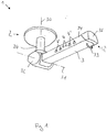
- FIG. 1 a perspective side view of a supply device 1 for providing at least one supply product according to a first embodiment is shown schematically.
- the supply device 1 for providing at least one supply product 1 comprises a mounting unit 2 for mounting the supply device on a support, preferably a ceiling of a room, and a cantilever arm 3, the cantilever arm 3 being arranged pivotably about a vertical pivot axis 30 relative to the mounting unit 2.
- the cantilever arm 3 has a plurality of connections 4, 4 ′, 4 ′′ for a supply product which are integrated directly into the cantilever arm 3 and which are provided on both sides 34 of the cantilever arm 3.
- Connections 4 for electrical current and connections 4 'for digital and / or analog data are provided on the side 34 visible here.
- a plurality of connections 4 ′′ for a medical gas are also formed on the side of the cantilever arm 3 that is opposite the visible side 34, wherein in each case one connection 4 ′′ for a medical gas for providing oxygen O 2 , medical air, carbon dioxide CO 2 , Nitrous oxide N 2 O, xenon Xe, nitrogen monoxide NO, helium He, and nitrogen N 2 is trained.
- connections 4 ′′ can be designed to provide carbon monoxide CO and / or hydrogen sulfide H 2 S.
- the cantilever arm 3 also has an operating handle 33 for positioning the cantilever arm 3, which is designed such that at least one line and / or at least one hose can be attached to the operating handle 33, in particular can be attached.
- the cantilever arm 3 can also be pivoted relative to the assembly unit 2 about a horizontal pivot axis 31 at least within a predetermined angular range.
- the angular range extends here between an orientation of the cantilever arm 3 perpendicular to the vertical pivot axis 30 in the gravitational direction up to an angle of 45 ° with respect to the alignment of the cantilever arm 3 perpendicular to the vertical pivot axis 30.
- other angles can also be specified for the range, for example 15 °, 30 ° or 60 °.
- the cantilever arm 3 is spaced from the assembly unit 2 by a column 24.
- the cantilever arm 3 has a joint unit 32, in which a first articulated bearing for providing the pivotability of the cantilever arm 3 about the vertical pivot axis 30, and a second articulated bearing for providing the pivotability of the cantilever arm 3 about the horizontal pivot axis 31 is integrated.
- a friction arrangement is also integrated in the joint unit 32, by means of which a position of the extension arm 3 relative to the vertical pivot axis 30 can be fixed by means of friction.
- an arrangement can also be integrated in the joint unit 32, by means of which a position of the extension arm 3 relative to the horizontal pivot axis 31 and / or to the vertical pivot axis 30 can be fixed by friction, magnetism and / or pneumatics.
- a motor unit preferably a motor unit having an electric motor, for supporting an adjustment of the position of the extension arm 3 relative to the vertical pivot axis 30 and / or to the horizontal pivot axis 31 can also be integrated in the supply device 1, preferably in the joint unit 32.
- a spring swivel stand is also integrated in the joint unit 32 to support an adjustment of the position of the extension arm 3 relative to the horizontal swivel axis 31 in the supply device.
- the cantilever arm 3 is designed as an extruded aluminum profile, at the end of which an end cover 36 is arranged.
- connection arm 3 In order to increase safety, a structural separation of electrical components, in particular the connections 4 for electrical current and the 4 ′ connections for digital and / or analog data, and the connections 4 ′′ for medical gases is provided in the extension arm 3.
- Figure 2 schematically shows a perspective side view of a supply device 1 for providing at least one supply product according to a further embodiment.
- the supply device 1 essentially corresponds to that in FIG Figure 1 shown. However, it additionally has 35 connections 4, 4 'on its underside.
- connections 4, 4 ', 4 "on the sides 34 are of modular, interchangeable design.
- FIG 3 schematically shows the supply device 1 Figure 2 in a further perspective side view. It can be clearly seen here that the assembly unit 2 has a flange 22 for the load-bearing fixing of the supply device 1 to a ceiling of a room to be equipped with the supply device 1. To improve hygiene, the flange 22 can be covered by a cover plate 20 which can be moved along the vertical pivot axis 30.
Abstract
Die vorliegende Erfindung betrifft eine Versorgungsvorrichtung (1) zum Bereitstellen zumindest eines Versorgungsprodukts, umfassend eine Montageeinheit (2) zum Montieren der Versorgungsvorrichtung an eine Abstützung, bevorzugt eine Decke eines Raumes, und einen Auslegerarm (3), wobei der Auslegerarm (3) relativ zur Montageeinheit (2) um eine vertikale Schwenkachse (30) schwenkbar angeordnet ist. Der Auslegerarm (3) weist ferner zumindest einen direkt in dem Auslegerarm (3) integrierten Anschluss (4, 4', 4") für ein Versorgungsprodukt auf.The invention relates to a supply device (1) for providing at least one supply product, comprising a mounting unit (2) for mounting the supply device on a support, preferably a ceiling of a room, and a cantilever arm (3), the cantilever arm (3) relative to the Mounting unit (2) is arranged to be pivotable about a vertical pivot axis (30). The cantilever arm (3) also has at least one connection (4, 4 ', 4 ") integrated directly in the cantilever arm (3) for a supply product.
Description
Die vorliegende Erfindung betrifft eine Versorgungsvorrichtung zum Bereitstellen zumindest eines Versorgungsprodukts.The present invention relates to a supply device for providing at least one supply product.
Es ist bekannt, in medizinischen Einrichtungen, beispielsweise Kliniken, Krankenhäusern, Arztpraxen und vergleichbaren Einrichtungen, in einem Behandlungsraum etwaige benötigte Versorgungsprodukte wie elektrischen Strom, Daten oder medizinische Gase über eine Versorgungseinheit bereitzustellen.It is known in medical facilities, for example clinics, hospitals, doctor's offices and comparable facilities, to provide any necessary supply products such as electrical current, data or medical gases in a treatment room via a supply unit.
Bekannte Versorgungseinheiten sind dabei mit einer Tragvorrichtung zu einem System kombiniert. Die Tragvorrichtung weist in der Regel einen Auslegerarm auf, welcher gegenüber einer an einer Decke des Behandlungsraums angeordneten Montageeinheit über mindestens eine Schwenkachse herum schwenkbar angeordnet ist. Die eigentliche Versorgungseinheit ist mit dem Auslegerarm über eine Schnittstelle verbunden beziehungsweise an diesen angekoppelt. Die Tragvorrichtung stellt mithin die Schnittstelle zur Decke dar und legt den möglichen Bewegungsbereich und Bewegungsradius fest, die Versorgungseinheit stellt wiederum die Versorgung mit elektrischem Strom, Daten und medizinischen Gasen bereit.Known supply units are combined with a carrying device to form a system. The carrying device generally has a cantilever arm, which is arranged so as to be pivotable about at least one pivot axis relative to an assembly unit arranged on a ceiling of the treatment room. The actual supply unit is connected to the cantilever arm via an interface or is coupled to it. The support device thus represents the interface to the ceiling and defines the possible range of motion and range of motion, the supply unit in turn provides the supply of electrical current, data and medical gases.
Bei den bekannten Kombinationen ist mithin stets eine Schnittstelle vonnöten, welche beide Teilsysteme, die Tragvorrichtung und die Versorgungseinheit, miteinander verbindet. Bei diesem Aufbau sind eine große Anzahl von Bauteilen und dementsprechend eine große Anzahl von Montageschritten zur Verbindung der Tragvorrichtung und der Versorgungseinheit nötig. Zudem liegen dadurch an den Verbindungsstellen zwischen Tragvorrichtung und Versorgungseinheit Fugen vor, welche eine Desinfektion des Systems aus Tragvorrichtung und Versorgungseinheit erschweren.In the known combinations, an interface is therefore always required which connects the two subsystems, the carrying device and the supply unit. With this construction, a large number of components and, accordingly, a large number of assembly steps are required to connect the carrying device and the supply unit. This also means that the connection points between Carrying device and supply unit Prevent joints that make disinfection of the system of carrying device and supply unit difficult.
Ausgehend von dem bekannten Stand der Technik ist es eine Aufgabe der vorliegenden Erfindung, eine verbesserte Versorgungsvorrichtung zum Bereitstellen zumindest eines Versorgungsprodukts bereitzustellen.Starting from the known prior art, it is an object of the present invention to provide an improved supply device for providing at least one supply product.
Die Aufgabe wird durch eine Versorgungsvorrichtung zum Bereitstellen zumindest eines Versorgungsprodukts mit den Merkmalen des Anspruchs 1 gelöst. Vorteilhafte Weiterbildungen ergeben sich aus den Unteransprüchen, der Beschreibung und den Figuren.The object is achieved by a supply device for providing at least one supply product with the features of claim 1. Advantageous further developments result from the subclaims, the description and the figures.
Entsprechend wird eine Versorgungsvorrichtung zum Bereitstellen zumindest eines Versorgungsprodukts vorgeschlagen, umfassend eine Montageeinheit zum Montieren der Vorrichtung an eine Abstützung, bevorzugt eine Decke eines Raumes, und einen Auslegerarm, wobei der Auslegerarm relativ zur Montageeinheit um eine vertikale Schwenkachse schwenkbar angeordnet ist. Erfindungsgemäß weist der Auslegerarm zumindest einen direkt in dem Auslegerarm integrierten Anschluss für ein Versorgungsprodukt auf.Accordingly, a supply device for providing at least one supply product is proposed, comprising a mounting unit for mounting the device on a support, preferably a ceiling of a room, and a cantilever arm, the cantilever arm being arranged to be pivotable relative to the mounting unit about a vertical pivot axis. According to the invention, the cantilever arm has at least one connection, integrated directly in the cantilever arm, for a supply product.
Dadurch, dass der Auslegerarm zumindest einen direkt in dem Auslegerarm integrierten Anschluss für ein Versorgungsprodukt aufweist, kann auf eine separate, an den Auslegerarm anzubringende Versorgungseinheit zum Bereitstellen des Versorgungsprodukts verzichtet werden. Hierdurch kann zum einen im Vergleich zu herkömmlichen Versorgungsvorrichtungen eine schlankere Bauform erzielt werden. Zudem ergibt sich ein einfacherer Aufbau, da auch die Bauteile, welche zum Verbinden des Auslegerarms und der ansonsten benötigten Versorgungseinheit notwendig wären, entfallen. Aufgrund des reduzierten Material- und Teilebedarfs lassen sich der Montageaufwand und die Herstellkosten reduzieren.Because the cantilever arm has at least one connection for a supply product that is directly integrated in the cantilever arm, a separate supply unit to be attached to the cantilever arm for providing the supply product can be dispensed with. In this way, on the one hand, a slimmer design can be achieved compared to conventional supply devices. In addition, there is a simpler construction, since the components which would be necessary to connect the cantilever arm and the supply unit otherwise required are also eliminated. Due to the reduced material and parts requirements, the assembly effort and the manufacturing costs can be reduced.
Durch die Integration des mindestens einen Anschlusses in den Auslegerarm kann zudem eine größere Durchgangshöhe für eine Person, beispielsweise medizinisches Personal, bereitgestellt werden, als dies bei Versorgungsvorrichtungen mit separater Versorgungseinheit der Fall ist. Zudem ist der benötigte Platzbedarf der Versorgungsvorrichtung gegenüber herkömmlichen Vorrichtungen reduziert.By integrating the at least one connection into the cantilever arm, a larger passage height can also be provided for a person, for example medical personnel, than is the case with supply devices with a separate supply unit. In addition, the space requirement of the supply device is reduced compared to conventional devices.
Aufgrund des Fehlens der Fugen an den Verbindungstellen zwischen dem Auslegerarm und der nicht benötigten Versorgungseinheit kann auch eine Reinigung, insbesondere eine Desinfektion, der Versorgungsvorrichtung vereinfacht werden. Zudem ist dadurch ein Absetzen und/oder Ansiedeln von Keimen an der Versorgungsvorrichtung erschwert. Folglich lassen sich die hygienischen Bedingungen insgesamt verbessern.Because the joints are missing at the connection points between the cantilever arm and the supply unit that is not required, cleaning, in particular disinfection, of the supply device can also be simplified. This also makes it more difficult for germs to settle and / or settle on the supply device. As a result, the overall hygiene conditions can be improved.
Unter "vertikal" wird hier insbesondere eine Ausrichtung parallel zur Gravitationsrichtung verstanden.“Vertical” here means in particular an orientation parallel to the direction of gravity.
Gemäß einer bevorzugen Ausführungsform ist eine Mehrzahl von Anschlüssen in den Auslegerarm integriert. Somit kann durch den Auslegerarm eine Vielzahl oder gar alle der benötigten Produkte bereitgestellt werden.According to a preferred embodiment, a plurality of connections are integrated in the extension arm. A large number or even all of the required products can thus be provided by the extension arm.
Bevorzugt ist zumindest ein Anschluss an einer Seite des Auslegerarms und/oder einer Unterseite des Auslegerarms angeordnet. Dadurch lassen sich die Variabilität der Versorgungsvorrichtung und die Erreichbarkeit der einzelnen Anschlüsse verbessern.At least one connection is preferably arranged on one side of the cantilever arm and / or on a lower side of the cantilever arm. The variability of the supply device and the accessibility of the individual connections can thereby be improved.
Gemäß einer weiter bevorzugten Ausführungsform ist ein Anschluss als Anschluss für elektrischen Strom, als Anschluss für digitale und/oder analoge Daten und/oder als Anschluss für ein medizinisches Gas ausgebildet, wobei ein Anschluss für ein medizinisches Gas, bevorzugt zum Bereitstellen von Sauerstoff (O2), medizinische Luft, sogenannter "Aer medicalis", Kohlenstoffdioxid (CO2), Lachgas (N2O), Xenon (Xe), Stickstoffmonoxid (NO), Helium (He), Stickstoff (N2), Kohlenmonoxid (CO) und/oder Schwefelwasserstoff (H2S) ausgebildet ist. Dadurch ist es möglich, nahezu alle oder gar alle benötigten Versorgungsprodukte durch die Versorgungsvorrichtung bereitzustellen.According to a further preferred embodiment, a connection is designed as a connection for electrical current, as a connection for digital and / or analog data and / or as a connection for a medical gas, a connection for a medical gas, preferably for providing oxygen (O 2 ), medical air, so-called "Aer medicalis", carbon dioxide (CO 2 ), nitrous oxide (N 2 O), xenon (Xe), nitrogen monoxide (NO), helium (He), nitrogen (N 2 ), carbon monoxide (CO) and / or hydrogen sulfide (H 2 S) is formed. This makes it possible to provide almost all or even all of the supply products required by the supply device.
Wenn der Auslegerarm einen Bediengriff zum Positionieren des Auslegerarms aufweist, kann eine Person, beispielsweise medizinisches Personal, die Position des Auslegerarms durch Betätigen des Bediengriffs in einfacher Weise verändern. In einer bevorzugten Weiterführung weist der Bediengriff mindestens ein Betätigungselement auf, durch welches eine elektrische, magnetische, hydraulische, pneumatische oder andersgeartete Unterstützung zum Positionieren des Auslegerarms aktiviert und/oder deaktiviert werden kann.If the cantilever arm has an operating handle for positioning the cantilever arm, a person, for example medical personnel, can easily change the position of the cantilever arm by actuating the operating handle. In a preferred development, the operating handle has at least one actuating element, by means of which an electrical, magnetic, hydraulic, pneumatic or other type of support for positioning the cantilever arm can be activated and / or deactivated.
Gemäß einer weiter bevorzugten Ausführungsform ist der Bediengriff derart ausgebildet, dass mindestens eine Leitung und/oder mindestens ein Schlauch an den Bediengriff angebracht werden kann, bevorzugt eingehängt werden kann. Dadurch ist es möglich, eine Zugentlastung für eine Steckverbindung zwischen dem Ende des Schlauches oder der Leitung und einem Anschluss bereitzustellen.According to a further preferred embodiment, the control handle is designed such that at least one line and / or at least one hose can be attached to the control handle, and can preferably be attached. This makes it possible to provide a strain relief for a plug connection between the end of the hose or the line and a connection.
Um eine größere Variabilität der Versorgungsvorrichtung zusätzlich bereitstellen zu können, kann der Auslegerarm relativ zur Montageeinheit ferner um eine horizontale Schwenkachse zumindest innerhalb eines vorgegebenen Winkelbereichs schwenkbar sein.In order to be able to provide a greater variability of the supply device, the extension arm can also be pivotable relative to the mounting unit about a horizontal pivot axis at least within a predetermined angular range.
Unter "horizontal" wird hier insbesondere eine Ausrichtung senkrecht zur vertikalen Schwenkachse verstanden."Horizontal" here means in particular an orientation perpendicular to the vertical pivot axis.
Gemäß einer weiter bevorzugten Ausführungsform ist eine Position des Auslegerarms relativ zur vertikalen Schwenkachse und/oder zur horizontalen Schwenkachse durch Reibung, Magnetismus und/oder Pneumatik fixierbar. Dadurch kann sichergestellt werden, dass der Auslegerarm sicher in seiner durch eine Person eingestellten Stellung bzw. Position verbleibt. So kann verhindert werden, dass es aufgrund einer ungewollten und unvorhergesehenen Bewegung des Auslegerarms zu Beschädigungen von Gegenständen oder Verletzungen von Personen kommt.According to a further preferred embodiment, a position of the cantilever arm can be fixed relative to the vertical pivot axis and / or to the horizontal pivot axis by means of friction, magnetism and / or pneumatics. This can ensure that the extension arm remains securely in its position or position set by a person. This can prevent damage to objects or injuries to persons due to an unwanted and unforeseen movement of the extension arm.
Um eine Verstellung der Position des Auslegerarms relativ zur vertikalen Schwenkachse und/oder zur horizontalen Schwenkachse zu unterstützen, kann eine Motoreinheit, bevorzugt eine einen Elektromotor aufweisende Motoreinheit, zum Unterstützen einer Verstellung der Position des Auslegerarms relativ zur vertikalen Schwenkachse und/oder zur horizontalen Schwenkachse in die Vorrichtung integriert sein.In order to support an adjustment of the position of the cantilever arm relative to the vertical pivot axis and / or to the horizontal pivot axis, a motor unit, preferably a motor unit having an electric motor, can support an adjustment of the position of the cantilever arm relative to the vertical pivot axis and / or to the horizontal pivot axis in the device can be integrated.
Alternativ oder zusätzlich kann auch ein Federschwenkstativ zum Unterstützen einer Verstellung der Position des Auslegerarms relativ zur vertikalen Schwenkachse und/oder zur horizontalen Schwenkachse in die Vorrichtung integriert sein.Alternatively or additionally, a spring swivel tripod can also be integrated into the device to support an adjustment of the position of the cantilever arm relative to the vertical swivel axis and / or to the horizontal swivel axis.
Gemäß einer weiter bevorzugten Ausführungsform ist der Auslegerarm als Strangpressprofil, bevorzugt als Aluminium-Strangpressprofil, ausgebildet und/oder ist zumindest ein Anschluss auswechselbar und/oder modular ausgebildet. Dadurch ist es möglich, den Auslegerarm in einfacher Weise in verschiedenen Längen bereitzustellen, und die Versorgungsvorrichtung bedarfsgerecht an eine jeweilige Einsatzsituation anzupassen.According to a further preferred embodiment, the extension arm is designed as an extruded profile, preferably as an extruded aluminum profile, and / or at least one connection is interchangeable and / or modular. This makes it possible to provide the cantilever arm in various lengths in a simple manner and to adapt the supply device to a particular application situation as required.
Wenn in dem Auslegerarm eine bauliche Trennung von elektrischen Bauteilen, insbesondere ein Anschluss für elektrischen Strom und/oder ein Anschluss für digitale und/oder analoge Daten, und ggf. Anschlüsse für medizinische Gase vorgesehen ist/sind, kann eine besonders sicher ausgebildete Versorgungsvorrichtung bereitgestellt werden.If a structural separation of electrical components, in particular a connection for electrical current and / or a connection for digital and / or analog data, and possibly connections for medical gases is / are provided in the extension arm, a particularly securely designed supply device can be provided .
Bevorzugte weitere Ausführungsformen der Erfindung werden durch die nachfolgende Beschreibung der Figuren näher erläutert. Dabei zeigen:
- Figur 1
- schematisch eine perspektivische Seitenansicht einer Versorgungsvorrichtung zum Bereitstellen zumindest eines Versorgungsprodukts gemäß einer ersten Ausführungsform;
Figur 2- schematisch eine perspektivische Seitenansicht einer Versorgungsvorrichtung zum Bereitstellen zumindest eines Versorgungsprodukts gemäß einer weiteren Ausführungsform; und
Figur 3- schematisch die Versorgungsvorrichtung aus
Figur 2
- Figure 1
- schematically shows a perspective side view of a supply device for providing at least one supply product according to a first embodiment;
- Figure 2
- schematically shows a perspective side view of a supply device for providing at least one supply product according to a further embodiment; and
- Figure 3
- schematically the supply device
Figure 2 in a further perspective side view.
Im Folgenden werden bevorzugte Ausführungsbeispiele anhand der Figuren beschrieben. Dabei werden gleiche, ähnliche oder gleichwirkende Elemente in den unterschiedlichen Figuren mit identischen Bezugszeichen versehen, und auf eine wiederholte Beschreibung dieser Elemente wird teilweise verzichtet, um Redundanzen zu vermeiden.Preferred exemplary embodiments are described below with reference to the figures. Identical, similar or equivalent elements in the different figures are provided with identical reference numerals, and a repeated description of these elements is partially omitted in order to avoid redundancies.
In
Dabei sind Anschlüsse 4 für elektrischen Strom und Anschlüsse 4' für digitale und/oder analoge Daten auf der hier sichtbaren Seite 34 vorgesehen. Auf der der hier sichtbaren Seite 34 gegenüberliegenden Seite des Auslegerarms 3 sind ferner eine Mehrzahl von Anschlüssen 4" für ein medizinisches Gas ausgebildet ist, wobei jeweils ein Anschluss 4" für ein medizinisches Gas zum Bereitstellen von Sauerstoff O2, medizinischer Luft, Kohlenstoffdioxid CO2, Lachgas N2O, Xenon Xe, Stickstoffmonoxid NO, Helium He, und Stickstoff N2 ausgebildet ist. Fernerhin können Anschlüsse 4" zum Bereitstellen von Kohlenmonoxid CO und/oder Schwefelwasserstoff H2S ausgebildet sein.
Der Auslegerarm 3 weist ferner einen Bediengriff 33 zum Positionieren des Auslegerarms 3 auf, welcher derart ausgebildet ist, dass mindestens eine Leitung und/oder mindestens ein Schlauch an den Bediengriff 33 angebracht werden kann, insbesondere eingehängt werden kann.The
In der vorliegenden Ausführungsform ist der Auslegerarm 3 relativ zur Montageeinheit 2 ferner um eine horizontale Schwenkachse 31 zumindest innerhalb eines vorgegebenen Winkelbereichs schwenkbar. Der Winkelbereich erstreckt sich hier zwischen einer Ausrichtung des Auslegerarms 3 senkrecht zur vertikalen Schwenkachse 30 in Gravitationsrichtung bis zu einem Winkel von 45° bezogen auf die Ausrichtung des Auslegerarms 3 senkrecht zur vertikalen Schwenkachse 30. Alternativ können auch andere Winkel für den Bereich vorgegeben werden, beispielsweise 15°, 30° oder 60°.In the present embodiment, the
Der Auslegerarm 3 ist von der Montageeinheit 2 durch eine Säule 24 beabstandet. Der Auslegerarm 3 weist eine Gelenkeinheit 32 auf, in welcher eine erste gelenkige Lagerung zur Bereitstellung der Schwenkbarkeit des Auslegerarms 3 um die vertikale Schwenkachse 30, sowie eine zweite gelenkige Lagerung zum Bereitstellen der Schwenkbarkeit des Auslegerarms 3 um die horizontale Schwenkachse 31 integriert ist.The
In der Gelenkeinheit 32 ist ferner eine Reibungsanordnung integriert, durch welche eine Position des Auslegerarms 3 relativ zur vertikalen Schwenkachse 30 mittels Reibung fixierbar ist.A friction arrangement is also integrated in the
Alternativ oder zusätzlich kann in der Gelenkeinheit 32 ferner eine Anordnung integriert sein, durch welche eine Position des Auslegerarms 3 relativ zur horizontalen Schwenkachse 31 und/oder zur vertikalen Schwenkachse 30 durch Reibung, Magnetismus und/oder Pneumatik fixierbar ist.Alternatively or additionally, an arrangement can also be integrated in the
Optional kann ferner eine Motoreinheit, bevorzugt eine einen Elektromotor aufweisende Motoreinheit, zum Unterstützen einer Verstellung der Position des Auslegerarms 3 relativ zur vertikalen Schwenkachse 30 und/oder zur horizontalen Schwenkachse 31 in die Versorgungsvorrichtung 1 integriert sein, bevorzugt in der Gelenkeinheit 32.Optionally, a motor unit, preferably a motor unit having an electric motor, for supporting an adjustment of the position of the
Vorliegend ist in der Gelenkeinheit 32 ferner ein Federschwenkstativ zum Unterstützen einer Verstellung der Position des Auslegerarms 3 relativ zur horizontalen Schwenkachse 31 in die Versorgungsvorrichtung integriert.In the present case, a spring swivel stand is also integrated in the
Der Auslegerarm 3 ist als Aluminium-Strangpressprofil ausgebildet, an dessem Ende eine Endabdeckung 36 angeordnet ist.The
Um die Sicherheit zu erhöhen, ist in dem Auslegerarm 3 eine bauliche Trennung von elektrischen Bauteilen, insbesondere den Anschlüssen 4 für elektrischen Strom und den 4' Anschlüssen für digitale und/oder analoge Daten, und den Anschlüssen 4" für medizinische Gase vorgesehen.In order to increase safety, a structural separation of electrical components, in particular the
Die Versorgungsvorrichtung 1 entspricht im Wesentlichen der in
Zudem sind die Anschlüsse 4, 4', 4" an den Seiten 34 modular auswechselbar ausgebildet.In addition, the
Soweit anwendbar, können alle einzelnen Merkmale, die in den Ausführungsbeispielen dargestellt sind, miteinander kombiniert und/oder ausgetauscht werden, ohne den Bereich der Erfindung zu verlassen.As far as applicable, all individual features that are shown in the exemplary embodiments can be combined and / or exchanged with one another without leaving the scope of the invention.
- 11
- VersorgungsvorrichtungSupply device
- 22nd
- MontageeinheitAssembly unit
- 2020th
- AbdeckplatteCover plate
- 2222
- Flanschflange
- 2424th
- Säulepillar
- 33rd
- AuslegerarmCantilever arm
- 3030th
- vertikale Schwenkachsevertical swivel axis
- 3131
- horizontale Schwenkachsehorizontal swivel axis
- 3232
- GelenkeinheitJoint unit
- 3333
- BediengriffControl handle
- 3434
- Seitepage
- 3535
- Unterseitebottom
- 3636
- EndabdeckungEnd cover
- 44th
- Anschluss für elektrischen StromConnection for electrical current
- 4'4 '
- Anschluss für digitale und/oder analoge DatenConnection for digital and / or analog data
- 4"4 "
- Anschluss für ein medizinisches GasConnection for a medical gas
Claims (10)
Priority Applications (5)
| Application Number | Priority Date | Filing Date | Title |
|---|---|---|---|
| EP18204425.5A EP3646840A1 (en) | 2018-11-05 | 2018-11-05 | Supply device for providing at least one supplying product |
| US17/289,806 US20210393464A1 (en) | 2018-11-05 | 2019-10-31 | Supply device for providing at least one supply product |
| PCT/EP2019/079939 WO2020094519A1 (en) | 2018-11-05 | 2019-10-31 | Supply device for providing at least one supply product |
| EP19801502.6A EP3876891B1 (en) | 2018-11-05 | 2019-10-31 | Supply device for providing at least one supplying product |
| CN201980072821.7A CN113056250A (en) | 2018-11-05 | 2019-10-31 | Supply device for providing at least one supply product |
Applications Claiming Priority (1)
| Application Number | Priority Date | Filing Date | Title |
|---|---|---|---|
| EP18204425.5A EP3646840A1 (en) | 2018-11-05 | 2018-11-05 | Supply device for providing at least one supplying product |
Publications (1)
| Publication Number | Publication Date |
|---|---|
| EP3646840A1 true EP3646840A1 (en) | 2020-05-06 |
Family
ID=64172412
Family Applications (2)
| Application Number | Title | Priority Date | Filing Date |
|---|---|---|---|
| EP18204425.5A Withdrawn EP3646840A1 (en) | 2018-11-05 | 2018-11-05 | Supply device for providing at least one supplying product |
| EP19801502.6A Active EP3876891B1 (en) | 2018-11-05 | 2019-10-31 | Supply device for providing at least one supplying product |
Family Applications After (1)
| Application Number | Title | Priority Date | Filing Date |
|---|---|---|---|
| EP19801502.6A Active EP3876891B1 (en) | 2018-11-05 | 2019-10-31 | Supply device for providing at least one supplying product |
Country Status (4)
| Country | Link |
|---|---|
| US (1) | US20210393464A1 (en) |
| EP (2) | EP3646840A1 (en) |
| CN (1) | CN113056250A (en) |
| WO (1) | WO2020094519A1 (en) |
Citations (3)
| Publication number | Priority date | Publication date | Assignee | Title |
|---|---|---|---|---|
| DE19748480A1 (en) * | 1997-11-03 | 1999-05-06 | Michael Schmidt | Carrier system for arranging electrical equipment, e.g. in clinical, medical, laboratory or workshop situations |
| US20060102811A1 (en) * | 2004-11-17 | 2006-05-18 | Maquet S.A. | Central distribution pole, and a support and a manufacturing method corresponding thereto |
| US20170014291A1 (en) * | 2012-07-24 | 2017-01-19 | Maquet (Suzhou) Co., Ltd. | Medical supply unit having an elbow joint part |
Family Cites Families (11)
| Publication number | Priority date | Publication date | Assignee | Title |
|---|---|---|---|---|
| DE2610140C3 (en) * | 1976-03-11 | 1981-06-19 | Drägerwerk AG, 2400 Lübeck | Ceiling swivel arm for operating rooms |
| DE4306803A1 (en) * | 1993-03-04 | 1994-09-08 | Kreuzer Gmbh & Co Ohg | Ceiling mount |
| CN201897059U (en) * | 2010-07-23 | 2011-07-13 | Ge医疗系统环球技术有限公司 | Hanging bracket for monitor of vascular machine |
| CN102087816A (en) * | 2010-12-04 | 2011-06-08 | 鸿富锦精密工业(深圳)有限公司 | Digital photo frame with multi-angle rotary bracket |
| CN202746868U (en) * | 2012-08-11 | 2013-02-20 | 符佳莹 | Remote control fixing support for television |
| CN203555838U (en) * | 2013-10-29 | 2014-04-23 | 湖南太阳龙医疗科技有限公司 | Bridge type nursing unit combination equipment for ICU (intensive care unit) |
| EP2876349B1 (en) * | 2013-11-20 | 2015-08-12 | Axis AB | Mounting bracket |
| CN206548613U (en) * | 2016-10-12 | 2017-10-13 | 南京迈瑞生物医疗电子有限公司 | Angiography equipment, operation lamp system, tower crane system and beacon coaxial configuration |
| CN106667585B (en) * | 2017-01-08 | 2023-07-28 | 迈柯唯医疗设备(苏州)有限公司 | Bidirectional release mechanism of telescopic element |
| CN107101137A (en) * | 2017-06-21 | 2017-08-29 | 杨谋森 | Movable ceiling lamp |
| CN207500768U (en) * | 2017-09-25 | 2018-06-15 | 苏州维亚克电气有限公司 | A kind of ceiling type universal adjusting device |
-
2018
- 2018-11-05 EP EP18204425.5A patent/EP3646840A1/en not_active Withdrawn
-
2019
- 2019-10-31 CN CN201980072821.7A patent/CN113056250A/en active Pending
- 2019-10-31 WO PCT/EP2019/079939 patent/WO2020094519A1/en unknown
- 2019-10-31 EP EP19801502.6A patent/EP3876891B1/en active Active
- 2019-10-31 US US17/289,806 patent/US20210393464A1/en active Pending
Patent Citations (3)
| Publication number | Priority date | Publication date | Assignee | Title |
|---|---|---|---|---|
| DE19748480A1 (en) * | 1997-11-03 | 1999-05-06 | Michael Schmidt | Carrier system for arranging electrical equipment, e.g. in clinical, medical, laboratory or workshop situations |
| US20060102811A1 (en) * | 2004-11-17 | 2006-05-18 | Maquet S.A. | Central distribution pole, and a support and a manufacturing method corresponding thereto |
| US20170014291A1 (en) * | 2012-07-24 | 2017-01-19 | Maquet (Suzhou) Co., Ltd. | Medical supply unit having an elbow joint part |
Also Published As
| Publication number | Publication date |
|---|---|
| EP3876891B1 (en) | 2024-01-31 |
| CN113056250A (en) | 2021-06-29 |
| WO2020094519A1 (en) | 2020-05-14 |
| EP3876891A1 (en) | 2021-09-15 |
| US20210393464A1 (en) | 2021-12-23 |
Similar Documents
| Publication | Publication Date | Title |
|---|---|---|
| DE3627517A1 (en) | CEILING TRIPOD | |
| DE202012104320U1 (en) | Station trolley, in particular visiting and nursing carts | |
| DE19748480B4 (en) | Carrier system for arranging electrical devices | |
| EP2987429B1 (en) | Vertically movable lifting bed device | |
| DE102013111935A1 (en) | A framework for holding a surgical robot, using such a frame in a surgical robotic system, and a robotic robot system having such a frame | |
| EP0363507A1 (en) | Mobile diagnostic X-ray apparatus | |
| DE202015103938U1 (en) | Carrying device and floor system between two articulated vehicle parts | |
| EP3646840A1 (en) | Supply device for providing at least one supplying product | |
| DE10107912B4 (en) | Device for installing supply lines | |
| BE1024814A1 (en) | A coupling device for mounting transformers and the method for their use | |
| DE202007018425U1 (en) | Workstation | |
| DE102018116425B4 (en) | presentation device | |
| EP3366430B1 (en) | Conveyor device for conveying objects and/or persons | |
| DE202016005731U1 (en) | Modular structure for a dental treatment unit | |
| DE102008002805A1 (en) | Shower and toilet chair | |
| DE3135088A1 (en) | Extension arm, especially for handling devices | |
| DE102009011271B4 (en) | Height-adjustable holding device for image projectors and the like | |
| WO2024067907A1 (en) | Energy supply device and linear system comprising an energy supply device | |
| DE1456451A1 (en) | Auxiliary control device for overhead traveling cranes or movable hoists | |
| DE212020000454U1 (en) | Positioning device for rotating element for swiveling the pier head of a swivel beam | |
| DE202017004834U1 (en) | T-shaped robot joint unit with at least two or more docking points for flexible design and retrofitting of robot arms | |
| DE10149046A1 (en) | Modular service center for providing social and medical services comprises a stationary central unit, a docking unit, and a container connected to each other by standard connections | |
| EP3095562B1 (en) | Handling device | |
| DE19817602A1 (en) | Computerized system for receiving and imparting information to visitors enables improved, automated reception of and information delivery to visitors | |
| DE202015007565U1 (en) | Device for X-ray examination |
Legal Events
| Date | Code | Title | Description |
|---|---|---|---|
| PUAI | Public reference made under article 153(3) epc to a published international application that has entered the european phase |
Free format text: ORIGINAL CODE: 0009012 |
|
| STAA | Information on the status of an ep patent application or granted ep patent |
Free format text: STATUS: THE APPLICATION HAS BEEN PUBLISHED |
|
| AK | Designated contracting states |
Kind code of ref document: A1 Designated state(s): AL AT BE BG CH CY CZ DE DK EE ES FI FR GB GR HR HU IE IS IT LI LT LU LV MC MK MT NL NO PL PT RO RS SE SI SK SM TR |
|
| AX | Request for extension of the european patent |
Extension state: BA ME |
|
| STAA | Information on the status of an ep patent application or granted ep patent |
Free format text: STATUS: THE APPLICATION IS DEEMED TO BE WITHDRAWN |
|
| 18D | Application deemed to be withdrawn |
Effective date: 20201107 |