JP5989155B2 - Engine equipment - Google Patents

Engine equipment Download PDF

Info

Publication number
JP5989155B2
JP5989155B2 JP2015021366A JP2015021366A JP5989155B2 JP 5989155 B2 JP5989155 B2 JP 5989155B2 JP 2015021366 A JP2015021366 A JP 2015021366A JP 2015021366 A JP2015021366 A JP 2015021366A JP 5989155 B2 JP5989155 B2 JP 5989155B2
Authority
JP
Japan
Prior art keywords
exhaust gas
exhaust
manifold
engine
dpf
Prior art date
Legal status (The legal status is an assumption and is not a legal conclusion. Google has not performed a legal analysis and makes no representation as to the accuracy of the status listed.)
Active
Application number
JP2015021366A
Other languages
Japanese (ja)
Other versions
JP2015083844A (en
Inventor
匡孝 光田
匡孝 光田
Current Assignee (The listed assignees may be inaccurate. Google has not performed a legal analysis and makes no representation or warranty as to the accuracy of the list.)
Yanmar Co Ltd
Original Assignee
Yanmar Co Ltd
Priority date (The priority date is an assumption and is not a legal conclusion. Google has not performed a legal analysis and makes no representation as to the accuracy of the date listed.)
Filing date
Publication date
Application filed by Yanmar Co Ltd filed Critical Yanmar Co Ltd
Priority to JP2015021366A priority Critical patent/JP5989155B2/en
Publication of JP2015083844A publication Critical patent/JP2015083844A/en
Application granted granted Critical
Publication of JP5989155B2 publication Critical patent/JP5989155B2/en
Active legal-status Critical Current
Anticipated expiration legal-status Critical

Links

Images

Classifications

    • YGENERAL TAGGING OF NEW TECHNOLOGICAL DEVELOPMENTS; GENERAL TAGGING OF CROSS-SECTIONAL TECHNOLOGIES SPANNING OVER SEVERAL SECTIONS OF THE IPC; TECHNICAL SUBJECTS COVERED BY FORMER USPC CROSS-REFERENCE ART COLLECTIONS [XRACs] AND DIGESTS
    • Y02TECHNOLOGIES OR APPLICATIONS FOR MITIGATION OR ADAPTATION AGAINST CLIMATE CHANGE
    • Y02TCLIMATE CHANGE MITIGATION TECHNOLOGIES RELATED TO TRANSPORTATION
    • Y02T10/00Road transport of goods or passengers
    • Y02T10/10Internal combustion engine [ICE] based vehicles
    • Y02T10/12Improving ICE efficiencies

Landscapes

  • Exhaust-Gas Circulating Devices (AREA)

Description

本願発明はエンジン装置に関するものである。   The present invention relates to an engine device.

昨今、ディーゼルエンジンに関する高次の排ガス規制が適用されるのに伴い、ディーゼルエンジンが搭載される農作業機や建設機械等に、排気ガス中の大気汚染物質を浄化処理する排気ガス浄化装置を搭載することが要望されつつある。排気ガス浄化装置としては、DPF(ディーゼルパティキュレートフィルタ)やNOx触媒等が知られている(特許文献1〜3参照)。   In recent years, due to the application of high-level exhaust gas regulations related to diesel engines, exhaust gas purification devices that purify air pollutants in exhaust gas are installed in agricultural machinery and construction machinery equipped with diesel engines. It is being requested. As an exhaust gas purification device, DPF (diesel particulate filter), NOx catalyst, etc. are known (refer to patent documents 1 to 3).

特開2000−145430号公報JP 2000-145430 A 特開2003−27922号公報Japanese Patent Laid-Open No. 2003-27922 特開2008−82201号公報JP 2008-82201 A

ところで、ディーゼルエンジンにDPFを直接搭載する場合、DPFに溶接固定された支持脚体をディーゼルエンジンに締結するが、ディーゼルエンジンの振動や応力が支持脚体やDPFに加わって、DPFと支持脚体との溶接部に応力集中が生じ、溶接部が破損したりDPFが変形・損傷したりし易いという問題があった。   By the way, when the DPF is directly mounted on the diesel engine, the support leg welded and fixed to the DPF is fastened to the diesel engine. However, the vibration and stress of the diesel engine are applied to the support leg and the DPF, and the DPF and the support leg. There is a problem that stress concentration occurs in the welded portion, and the welded portion is easily broken or the DPF is easily deformed or damaged.

本願発明は、上記のような現状を検討して改善を施したエンジン装置を提供することを技術的課題とするものである。   This invention makes it a technical subject to provide the engine apparatus which improved the present condition as mentioned above.

本発明のエンジン装置は、シリンダヘッドのうちエンジン出力軸線と平行な前後一側部に吸気マニホールドを、前後他側部に排気マニホールドを備えているとともに、エンジン出力軸線と直交する左側面に設けたフライホイールハウジングと、前記排気マニホールドから排出される排気ガスの一部を冷却させる排気ガス冷却手段であるEGRクーラと、該EGRクーラと連結して前記排気マニホールドからの排気ガスを前記吸気マニホールドに還流させる排気ガス再循環装置を備えているエンジン装置であって、前記排気マニホールドからの排気ガスを浄化する複数のガス浄化フィルタ及び前記各ガス浄化フィルタを収容する複数のケースを有する排気ガス浄化装置を備え、前記排気ガス浄化装置は、前記エンジン出力軸と直行する方向に延びた姿勢で前記フライホイールハウジングの上方に支持脚体を介して着脱可能に連結されるとともに、その長手方向一端側と他端側とに、排気ガス入口管と排気ガス出口管とがそれぞれ振り分けて突設され、前記排気ガス入口管が前記排気マニホールドの排気出口と連結されており、前記シリンダヘッドの一側部に前記排気ガス再循環装置が設置される一方で、前記シリンダヘッドの他側部に前記EGRクーラの本体ケースが設置され、前記排気ガス再循環装置の本体ケースに連結される排気ガス管は前記シリンダヘッドの上面を跨ぐように取り回されて前記EGRクーラの出口側と連結されているというものである。 The engine device of the present invention includes an intake manifold on one front and rear side parallel to the engine output axis of the cylinder head, an exhaust manifold on the other front and rear sides, and a left side surface orthogonal to the engine output axis. A flywheel housing , an EGR cooler that is an exhaust gas cooling means for cooling a part of the exhaust gas discharged from the exhaust manifold, and an exhaust gas from the exhaust manifold connected to the EGR cooler to return to the intake manifold An exhaust gas recirculation apparatus comprising: a plurality of gas purification filters for purifying exhaust gas from the exhaust manifold; and an exhaust gas purification apparatus having a plurality of cases for housing the gas purification filters. wherein the exhaust gas purifying apparatus, extending in a direction orthogonal to the engine output shaft In this posture, the flywheel housing is detachably connected to the upper part of the flywheel housing via a support leg, and an exhaust gas inlet pipe and an exhaust gas outlet pipe are respectively distributed to one end side and the other end side in the longitudinal direction. The exhaust gas inlet pipe is connected to the exhaust outlet of the exhaust manifold, and the exhaust gas recirculation device is installed on one side of the cylinder head, while the other side of the cylinder head A main body case of the EGR cooler is installed, and an exhaust gas pipe connected to the main body case of the exhaust gas recirculation device is routed across the upper surface of the cylinder head and connected to the outlet side of the EGR cooler. It is that.

このようなエンジン装置において、前記シリンダヘッドの一側部において、前記排気ガス再循環装置の本体ケースが前記吸気マニホールドの上方で固定される一方で、前記シリンダヘッドの他側部において、前記EGRクーラが前記排気マニホールドの上方で固定されており、前記排気マニホールドは、左端部側から左向きに突出して前記排気出口を設けて前記排気ガス浄化装置の排気ガス入口管と連結する一方で、左端部側がU字形状のEGRガス取出し管を介して前記EGRクーラの入口側と連結するものであってもよい。 In such an engine device, the main body case of the exhaust gas recirculation device is fixed above the intake manifold at one side of the cylinder head, while the EGR cooler is fixed at the other side of the cylinder head. Is fixed above the exhaust manifold, and the exhaust manifold protrudes leftward from the left end side to provide the exhaust outlet and is connected to the exhaust gas inlet pipe of the exhaust gas purification device, while the left end side is It may be connected to the inlet side of the EGR cooler via a U-shaped EGR gas extraction pipe .

更に、上述のエンジン装置において、冷却水循環用の冷却水ポンプがエンジンの前記排気マニホールド側に配置されるとともに、前記冷却水ポンプと前記EGRクーラとをつなぐとともにエンジン自体への冷却水系統とは別系統となる冷却水流通経路が、エンジンの前記排気マニホールド側に配管されているものであってもよい。   Further, in the above-described engine device, a cooling water pump for circulating cooling water is disposed on the exhaust manifold side of the engine, and connects the cooling water pump and the EGR cooler and is separate from the cooling water system to the engine itself. A cooling water flow path serving as a system may be provided on the exhaust manifold side of the engine.

本発明によると、EGRクーラ及びEGR本体それぞれを排気マニホールド及び吸気マニホールドの上面側に配置する構成とすることで、エンジン(シリンダヘッド)の上方空間を利用して、再循環排気ガス管の取り回しを短くできるとともに、EGR関連の部材をコンパクトに配置でき、組付け作業性やメンテナンス性の向上を図れる。   According to the present invention, the EGR cooler and the EGR main body are arranged on the upper surface side of the exhaust manifold and the intake manifold, respectively, so that the recirculated exhaust gas pipe can be routed using the space above the engine (cylinder head). It can be shortened, EGR-related members can be arranged in a compact manner, and assembly workability and maintainability can be improved.

又、排気マニホールドの長手方向の一端と他端に振り分けて、排気ガス浄化装置とEGRクーラとを連結する構成とすることで、排気ガス浄化装置の搭載位置が邪魔にならず、エンジン(シリンダヘッド)の上方空間を利用して、EGR本体及びEGRクーラ等を配置したり、再循環排気ガス管をコンパクトに取り回したりできる。   Further, the exhaust manifold is divided into one end and the other end in the longitudinal direction to connect the exhaust gas purifier and the EGR cooler, so that the mounting position of the exhaust gas purifier does not get in the way, and the engine (cylinder head) ), The EGR main body, the EGR cooler, and the like can be arranged, and the recirculated exhaust gas pipe can be handled compactly.

更に、排気ガス浄化装置を排気マニホールドの前方(側方)に配置させることによって、排気ガス浄化装置をシリンダヘッドの高さよりも低い位置とすることができるため、作業車両にエンジン装置を組み付ける際に、エンジン装置上方の構成部品に対する配置に規制がなくなり、設計の自由度が増す。又、シリンダヘッド、排気マニホールド及び吸気マニホールドの上面側が露出した状態とし、メンテナンス作業をし易い状態に構成できる。一方、排気ガス浄化装置をフライホイールハウジングの上方に配置させることによって、排気ガス浄化装置をシリンダヘッドの高さよりも低い位置とすることができるため、作業車両にエンジン装置を組み付ける際に、エンジン装置上方の構成部品に対する配置に規制がなくなり、設計の自由度が増す。又、シリンダヘッド、排気マニホールド及び吸気マニホールドの上面側が露出した状態とし、メンテナンス作業をし易い状態に構成できる。   Further, by disposing the exhaust gas purification device in front (side) of the exhaust manifold, the exhaust gas purification device can be placed at a position lower than the height of the cylinder head. Therefore, when assembling the engine device to the work vehicle In addition, there is no restriction on the arrangement of the components above the engine device, and the degree of freedom in design increases. Further, the upper surface side of the cylinder head, the exhaust manifold and the intake manifold can be exposed so that maintenance work can be easily performed. On the other hand, by disposing the exhaust gas purification device above the flywheel housing, the exhaust gas purification device can be placed at a position lower than the height of the cylinder head. Therefore, when the engine device is assembled to the work vehicle, There is no restriction on the arrangement of the upper components, and the degree of freedom in design increases. Further, the upper surface side of the cylinder head, the exhaust manifold and the intake manifold can be exposed so that maintenance work can be easily performed.

又、本発明によれば、EGRクーラに対する冷却水流通経路が冷却水ポンプ及びEGRクーラのある排気マニホールド側にまとまることになるため、冷却水流通経路の取り回しが容易になり、組付け作業性の向上に寄与できる。又、エンジンの冷却に寄与した(温度が上昇した)後の高温になった冷却水がEGRクーラに供給されることがないため、冷却水の温度上昇に伴う不具合を防止でき、EGRクーラの冷却性能の向上を図れる。   In addition, according to the present invention, the cooling water flow path for the EGR cooler is gathered on the exhaust manifold side where the cooling water pump and the EGR cooler are provided, so that the cooling water flow path can be easily routed and the assembly workability can be improved. It can contribute to improvement. In addition, since the high-temperature cooling water that has contributed to the cooling of the engine (the temperature has risen) is not supplied to the EGR cooler, it is possible to prevent problems associated with the temperature rise of the cooling water and to cool the EGR cooler. Improve performance.

又、本発明のエンジン装置において、エンジンからの排気ガスを浄化する複数のガス浄化フィルタ及び前記各ガス浄化フィルタを収容する複数のケースを有する排気ガス浄化装置と、前記エンジンに前記排気ガス浄化装置を支持させる支持脚体とを備えているエンジン装置であって、前記排気ガス浄化装置において隣り合う前記ケース同士は、ボルトによって着脱可能に締結するフランジ体を介して連結されており、前記フランジ体は、前記支持脚体を介して前記エンジンに連結されているものとすれば、フランジ体や支持脚体をケースに溶接することなく別体に構成することになる。このため、溶接起因の応力集中や歪の問題を回避できる。ケースに対するフランジ体及び支持脚体の組付け作業性が高い。   Further, in the engine apparatus of the present invention, an exhaust gas purification apparatus having a plurality of gas purification filters for purifying exhaust gas from the engine, a plurality of cases for accommodating the gas purification filters, and the exhaust gas purification apparatus in the engine. An engine device comprising a support leg for supporting the exhaust gas purification device, wherein the cases adjacent to each other in the exhaust gas purification device are connected to each other via a flange body detachably fastened by a bolt. If it is connected to the engine via the support legs, the flange body and the support legs are constructed separately without welding to the case. For this reason, the problem of stress concentration and distortion caused by welding can be avoided. Assembling workability of the flange body and the supporting leg body to the case is high.

そして、前記排気ガス浄化装置は、その長手方向一端側に設けられた排気ガス入口管から、前記エンジンの排気ガスを取り込むように構成されており、前記排気ガス浄化装置の前記排気ガス入口管が前記エンジンの排気マニホールドに連結されている一方、前記排気ガス浄化装置の長手方向他端側にある前記フランジ体が、前記エンジンのシリンダヘッドに取り付けられた前記支持脚体に連結されているものとすることで、排気マニホールドと支持脚体とで排気ガス浄化装置の重心を長手方向両側から挟むようにして、排気ガス浄化装置を安定支持できる。エンジンの高剛性部品であるシリンダヘッドと支持脚体とを利用して、排気ガス浄化装置を高剛性で且つ安定的に支持でき、振動等による排気ガス浄化装置の損傷を抑制できる。   The exhaust gas purification device is configured to take in the exhaust gas of the engine from an exhaust gas inlet tube provided at one end in the longitudinal direction, and the exhaust gas inlet tube of the exhaust gas purification device is The flange body on the other end side in the longitudinal direction of the exhaust gas purification device is connected to the support leg body attached to the cylinder head of the engine while being connected to the exhaust manifold of the engine. By doing so, the exhaust gas purification device can be stably supported by sandwiching the center of gravity of the exhaust gas purification device from both sides in the longitudinal direction between the exhaust manifold and the support legs. By utilizing the cylinder head and the support leg, which are high rigidity parts of the engine, the exhaust gas purification device can be stably supported with high rigidity, and damage to the exhaust gas purification device due to vibration or the like can be suppressed.

DPFの正面視断面図である。It is front view sectional drawing of DPF. 同外観底面図である。It is the same external appearance bottom view. 図1の正面視分解断面図である。FIG. 2 is an exploded front sectional view of FIG. 1. DPFを排気マニホールドの前方に配置した第1実施形態のディーゼルエンジンの正面図である。It is a front view of the diesel engine of 1st Embodiment which has arrange | positioned DPF ahead of the exhaust manifold. ディーゼルエンジンの背面図である。It is a rear view of a diesel engine. ディーゼルエンジンの平面図である。It is a top view of a diesel engine. ディーゼルエンジンの左側面図である。It is a left view of a diesel engine. ディーゼルエンジンの右側面図である。It is a right view of a diesel engine. DPFを省略した状態を示すディーゼルエンジンの正面図である。It is a front view of the diesel engine which shows the state where DPF was omitted. DPFをフライホイールハウジングの上方に配置した第2実施形態のディーゼルエンジンの正面図である。It is a front view of the diesel engine of 2nd Embodiment which has arrange | positioned DPF above the flywheel housing. ディーゼルエンジンの平面図である。It is a top view of a diesel engine. DPFの排気ガス入口管を排気マニホールドの出口部に直結した第3実施形態のディーゼルエンジンの平面図である。It is a top view of the diesel engine of 3rd Embodiment which connected the exhaust-gas inlet pipe of DPF directly to the exit part of an exhaust manifold. DPFを排気マニホールドの上方に配置した参考例のディーゼルエンジンの正面図である。It is a front view of the diesel engine of the reference example which has arrange | positioned DPF above the exhaust manifold. 参考例で採用されたDPFの正面視断面図である。It is front sectional drawing of DPF employ | adopted by the reference example. バックホウの側面図である。It is a side view of a backhoe. バックホウの平面図である。It is a top view of a backhoe. フォークリフトカーの側面図である。It is a side view of a forklift car. フォークリフトカーの平面図である。It is a top view of a forklift car.

以下に、本発明を具体化した実施形態を図面に基づいて説明する。   DESCRIPTION OF EMBODIMENTS Embodiments embodying the present invention will be described below with reference to the drawings.

(1).DPFの全体構造
まず、図1〜図3を参照しながら、排気ガス浄化装置の全体構造を説明する。図1〜図3に示す如く、排気ガス浄化装置としての連続再生式のディーゼルパティキュレートフィルタ1(以下、DPFという)を備えている。DPF1は、排気ガス中の粒子状物質(PM)等を物理的に捕集するためのものである。実施形態のDPF1は、二酸化窒素(NO2)を生成する白金等のディーゼル酸化触媒2と、捕集した粒子状物質(PM)を比較的低温で連続的に酸化除去するハニカム構造のスートフィルタ3とを、排気ガスの移動方向(図1の左側から右側方向)に直列に並べた構造になっている。DPF1は、スートフィルタ3が連続的に再生されるように構成している。DPF1によって、排気ガス中の粒子状物質(PM)の除去に加え、排気ガス中の一酸化炭素(CO)や炭化水素(HC)を低減できる。
(1). First, the overall structure of the exhaust gas purifying apparatus will be described with reference to FIGS. As shown in FIGS. 1 to 3, a continuously regenerating diesel particulate filter 1 (hereinafter referred to as a DPF) is provided as an exhaust gas purification device. The DPF 1 is for physically collecting particulate matter (PM) and the like in the exhaust gas. The DPF 1 of the embodiment includes a diesel oxidation catalyst 2 such as platinum that generates nitrogen dioxide (NO2), and a soot filter 3 having a honeycomb structure that continuously oxidizes and removes the collected particulate matter (PM) at a relatively low temperature. Are arranged in series in the exhaust gas movement direction (from the left side to the right side in FIG. 1). The DPF 1 is configured so that the soot filter 3 is continuously regenerated. The DPF 1 can reduce carbon monoxide (CO) and hydrocarbons (HC) in the exhaust gas in addition to the removal of particulate matter (PM) in the exhaust gas.

(2).ディーゼル酸化触媒の取付け構造
図1〜図3を参照して、ディーゼル酸化触媒2の取付け構造を説明する。図1〜図3に示す如く、後述するディーゼルエンジン70が排出した排気ガスを浄化するガス浄化フィルタとしてのディーゼル酸化触媒2は、耐熱金属材料製で略筒型の触媒内側ケース4内に設けられている。触媒内側ケース4は、耐熱金属材料製で略筒型の触媒外側ケース5内に設けられている。即ち、ディーゼル酸化触媒2の外側にマット状のセラミックファイバー製触媒断熱材6を介して触媒内側ケース4を被嵌させている。また、触媒内側ケース4の外側に端面I字状の薄板製支持体7を介して触媒外側ケース5を被嵌させている。なお、触媒断熱材6によってディーゼル酸化触媒2が保護される。触媒内側ケース4に伝わる触媒外側ケース5の応力(変形力)を薄板製支持体7にて低減させる。
(2). Attachment structure of diesel oxidation catalyst The attachment structure of the diesel oxidation catalyst 2 will be described with reference to FIGS. As shown in FIGS. 1 to 3, a diesel oxidation catalyst 2 as a gas purification filter for purifying exhaust gas discharged from a diesel engine 70 described later is provided in a substantially cylindrical catalyst inner case 4 made of a heat-resistant metal material. ing. The catalyst inner case 4 is made of a heat resistant metal material and is provided in a substantially cylindrical catalyst outer case 5. That is, the catalyst inner case 4 is fitted on the outside of the diesel oxidation catalyst 2 via the mat-shaped ceramic fiber catalyst heat insulating material 6. Further, the catalyst outer case 5 is fitted on the outer side of the catalyst inner case 4 via a thin plate support 7 having an I-shaped end face. Note that the diesel oxidation catalyst 2 is protected by the catalyst heat insulating material 6. The stress (deformation force) of the catalyst outer case 5 transmitted to the catalyst inner case 4 is reduced by the thin plate support 7.

図1〜図3に示す如く、触媒内側ケース4及び触媒外側ケース5の一側端部に円板状の側蓋体8を溶接にて固着している。側蓋体8に座板体9を介してセンサ接続プラグ10を固着している。ディーゼル酸化触媒2の一側端面2aと左側蓋体8とをガス流入空間用一定距離L1だけ離間させて対向させる。ディーゼル酸化触媒2の左側端面2aと左側蓋体8との間に排気ガス流入空間11を形成している。触媒内側ケース4及び触媒外側ケース5における排気ガス流入空間11の部位にはセンサ接続プラグ10が固着されている。なお、センサ接続プラグ10には、図示しない入口側排気ガス圧力センサや入口側排気ガス温度センサ等が接続される。   As shown in FIGS. 1 to 3, a disc-shaped side cover 8 is fixed to one end of the catalyst inner case 4 and the catalyst outer case 5 by welding. A sensor connection plug 10 is fixed to the side lid 8 via a seat plate 9. The one end face 2a of the diesel oxidation catalyst 2 and the left lid 8 are opposed to each other with a predetermined distance L1 for gas inflow space. An exhaust gas inflow space 11 is formed between the left end face 2 a of the diesel oxidation catalyst 2 and the left lid 8. A sensor connection plug 10 is fixed to the exhaust gas inflow space 11 in the catalyst inner case 4 and the catalyst outer case 5. The sensor connection plug 10 is connected to an unillustrated inlet side exhaust gas pressure sensor, an inlet side exhaust gas temperature sensor, and the like.

図1及び図3に示す如く、排気ガス流入空間11が形成された触媒内側ケース4及び触媒外側ケース5の一側端部に楕円形状の排気ガス流入口12を開口させている。楕円形状の排気ガス流入口12は、排気ガス移動方向(前記ケース4,5の中心線方向)を短尺直
径とし、排気ガス移動方向(前記ケース4,5の円周方向)に直交する方向を長尺直径に形
成している。触媒内側ケース4の開口縁13と触媒外側ケース5の開口縁14の間に閉塞リング体15を挟持状に固着している。触媒内側ケース4の開口縁13と触媒外側ケース5の開口縁14の間の隙間が閉塞リング体15によって閉鎖される。触媒内側ケース4と触媒外側ケース5の間に排気ガスが流入するのを、閉塞リング体15によって防止している。
As shown in FIGS. 1 and 3, an elliptical exhaust gas inlet 12 is opened at one end of the catalyst inner case 4 and the catalyst outer case 5 in which the exhaust gas inflow space 11 is formed. The elliptical exhaust gas inlet 12 has a short diameter in the exhaust gas movement direction (center line direction of the cases 4 and 5) and a direction orthogonal to the exhaust gas movement direction (circumferential direction of the cases 4 and 5). It has a long diameter. A closing ring body 15 is fixed between the opening edge 13 of the catalyst inner case 4 and the opening edge 14 of the catalyst outer case 5 in a sandwiched manner. A gap between the opening edge 13 of the catalyst inner case 4 and the opening edge 14 of the catalyst outer case 5 is closed by the closing ring body 15. An exhaust ring 15 prevents the exhaust gas from flowing between the catalyst inner case 4 and the catalyst outer case 5.

図1及び図3に示す如く、排気ガス流入口12が形成された触媒外側ケース5の外側面に排気ガス入口管16を配置している。排気ガス入口管16における小径側の真円形の開口端部16aに排気接続フランジ体17を溶接している。詳細は後述するが、排気接続フランジ体17は、剛体構造の連結部材86を介して、ディーゼルエンジン70の排気マニホールド71に締結されている。排気ガス入口管16における大径側の真円形の開口端部16bは、触媒外側ケース5の外側面に溶接されている。排気ガス入口管16は、小径側の真円形の開口端部16aから大径側の真円形の開口端部16bに向けて末広がり形状(ラッパ状)に形成されている。   As shown in FIGS. 1 and 3, an exhaust gas inlet pipe 16 is disposed on the outer surface of the catalyst outer case 5 in which the exhaust gas inlet 12 is formed. An exhaust connection flange body 17 is welded to a true circular open end 16a on the small diameter side of the exhaust gas inlet pipe 16. Although the details will be described later, the exhaust connection flange body 17 is fastened to the exhaust manifold 71 of the diesel engine 70 via a connecting member 86 having a rigid structure. A large circular opening end 16 b on the large diameter side of the exhaust gas inlet pipe 16 is welded to the outer surface of the catalyst outer case 5. The exhaust gas inlet pipe 16 is formed in a divergent shape (a trumpet shape) from the small-diameter-side perfect circular opening end 16a toward the large-diameter-side perfect circular opening end 16b.

図1及び図3に示す如く、触媒外側ケース5における外側面の一側端部には、真円形に形成された大径側の開口端部16bが、排気ガス入口管16にて開口縁14を覆うように溶接されている。この場合、楕円形状の排気ガス流入口12に対して、排気ガス入口管16(大径側の開口端部16b)は、排気ガス移動下流側(触媒外側ケース5の右側)にオフセットして配置されている。すなわち、楕円形状の排気ガス流入口12は、排気ガス入口管16(大径側の開口端部16b)に対して、排気ガス移動上流側(触媒外側ケース5の左側)にオフセットされている。   As shown in FIGS. 1 and 3, a large-diameter opening end 16 b formed in a true circle is formed at one end of the outer surface of the catalyst outer case 5. It is welded to cover. In this case, the exhaust gas inlet pipe 16 (large-diameter-side opening end portion 16b) is offset with respect to the elliptical exhaust gas inlet 12, and is arranged offset to the exhaust gas movement downstream side (the right side of the catalyst outer case 5). Has been. That is, the elliptical exhaust gas inlet 12 is offset to the exhaust gas movement upstream side (the left side of the catalyst outer case 5) with respect to the exhaust gas inlet pipe 16 (large-diameter side opening end portion 16b).

上記の構成により、ディーゼルエンジン70の排気ガスが、排気マニホールド71から排気ガス入口管16に入り込み、排気ガス入口管16から排気ガス流入口12を介して排気ガス流入空間11に入り込み、ディーゼル酸化触媒2にこの左側端面2aから供給される。ディーゼル酸化触媒2の酸化作用によって、二酸化窒素(NO2)が生成される。   With the above configuration, the exhaust gas of the diesel engine 70 enters the exhaust gas inlet pipe 16 from the exhaust manifold 71, enters the exhaust gas inflow space 11 from the exhaust gas inlet pipe 16 through the exhaust gas inlet 12, and the diesel oxidation catalyst. 2 is supplied from the left end face 2a. Nitrogen dioxide (NO 2) is generated by the oxidation action of the diesel oxidation catalyst 2.

(3).スートフィルタの取付け構造
図1及び図3を参照して、スートフィルタ3の取付け構造を説明する。図1及び図3に示す如く、ディーゼルエンジン70が排出した排気ガスを浄化するガス浄化フィルタとしてのスートフィルタ3は、耐熱金属材料製で略筒型のフィルタ内側ケース20内に設けられている。内側ケース4は、耐熱金属材料製で略筒型のフィルタ外側ケース21内に設けられている。すなわち、スートフィルタ3の外側にマット状のセラミックファイバー製フィルタ断熱材22を介してフィルタ内側ケース20を被嵌させている。なお、フィルタ断熱材22によってスートフィルタ3が保護される。
(3). Soot Filter Mounting Structure The soot filter 3 mounting structure will be described with reference to FIGS. 1 and 3. As shown in FIGS. 1 and 3, the soot filter 3 as a gas purification filter for purifying exhaust gas discharged from the diesel engine 70 is provided in a substantially cylindrical filter inner case 20 made of a heat-resistant metal material. The inner case 4 is made of a heat-resistant metal material and is provided in a substantially cylindrical filter outer case 21. That is, the filter inner case 20 is fitted on the outside of the soot filter 3 via the mat-shaped ceramic fiber filter heat insulating material 22. The soot filter 3 is protected by the filter heat insulating material 22.

図1及び図3に示す如く、触媒外側ケース5の排気ガス移動下流側(右側)の端部に触媒側フランジ25を溶接する。フィルタ内側ケース20の排気ガス移動方向の中間と、フィルタ外側ケース21の排気ガス移動上流側(左側)の端部にフィルタ側フランジ26を溶接する。触媒側フランジ25と、フィルタ側フランジ26とを、ボルト27及びナット28によって着脱可能に締結している。なお、円筒形の触媒内側ケース4の直径寸法と、円筒形のフィルタ内側ケース20の直径寸法とが略同一寸法である。また、円筒形の触媒外側ケース5の直径寸法と、円筒形のフィルタ外側ケース21の直径寸法とが略同一寸法である。   As shown in FIGS. 1 and 3, the catalyst side flange 25 is welded to the exhaust gas movement downstream side (right side) of the catalyst outer case 5. The filter side flange 26 is welded to the middle of the filter inner case 20 in the exhaust gas movement direction and the end of the filter outer case 21 on the upstream side (left side) of the exhaust gas movement. The catalyst side flange 25 and the filter side flange 26 are detachably fastened by bolts 27 and nuts 28. The diameter of the cylindrical catalyst inner case 4 and the diameter of the cylindrical filter inner case 20 are substantially the same. Further, the diameter of the cylindrical catalyst outer case 5 and the diameter of the cylindrical filter outer case 21 are substantially the same.

図1に示す如く、触媒側フランジ25とフィルタ側フランジ26を介して、触媒外側ケース5にフィルタ外側ケース21が連結された状態では、触媒内側ケース4の排気ガス移動下流側(他側)の端部に、フィルタ内側ケース20の排気ガス移動上流側(一側)の端部が、センサ取付け用一定間隔L2だけ離間して対峙する。即ち、触媒内側ケース4の排気ガス移動下流側(他側)の端部と、フィルタ内側ケース20の排気ガス移動上流側(一側)の端部との間に、センサ取付け空間29が形成される。センサ取付け空間29位置の触媒外側ケース5に、センサ接続プラグ50を固着している。センサ接続プラグ50には、図示しないフィルタ入口側排気ガス圧力センサやフィルタ入口側排気ガス温度センサ(サーミスタ)等が接続される。   As shown in FIG. 1, in a state where the filter outer case 21 is connected to the catalyst outer case 5 via the catalyst side flange 25 and the filter side flange 26, the exhaust gas movement downstream side (other side) of the catalyst inner case 4 is provided. The end of the filter inner case 20 on the upstream side (one side) of the exhaust gas movement is opposed to the end by being spaced apart by a predetermined sensor mounting interval L2. That is, a sensor mounting space 29 is formed between the end of the catalyst inner case 4 on the downstream side (other side) of the exhaust gas movement and the end of the filter inner case 20 on the upstream side (one side) of the exhaust gas movement. The A sensor connection plug 50 is fixed to the catalyst outer case 5 at the sensor mounting space 29 position. The sensor connection plug 50 is connected to a filter inlet side exhaust gas pressure sensor (not shown), a filter inlet side exhaust gas temperature sensor (thermistor), and the like.

図3に示す如く、触媒内側ケース4の排気ガス移動方向の円筒長さL3よりも、触媒外側ケース5の排気ガス移動方向の円筒長さL4を長く形成している。フィルタ内側ケース20の排気ガス移動方向の円筒長さL5よりも、フィルタ外側ケース21の排気ガス移動方向の円筒長さL6を短く形成している。センサ取付け空間29の一定間隔L2と、触媒内側ケース4の円筒長さL3と、フィルタ内側ケース20の円筒長さL5とを加算した長さ(L2+L3+L5)が、触媒外側ケース5の円筒長さL4と、フィルタ外側ケース21の円筒長さL6とを加算した長さ(L4+L6)に略等しくなるように構成している。   As shown in FIG. 3, the cylindrical length L4 of the catalyst outer case 5 in the exhaust gas movement direction is longer than the cylindrical length L3 of the catalyst inner case 4 in the exhaust gas movement direction. The cylindrical length L6 of the filter outer case 21 in the exhaust gas movement direction is shorter than the cylindrical length L5 of the filter inner case 20 in the exhaust gas movement direction. A length (L2 + L3 + L5) obtained by adding the constant interval L2 of the sensor mounting space 29, the cylindrical length L3 of the catalyst inner case 4 and the cylindrical length L5 of the filter inner case 20 is the cylindrical length L4 of the catalyst outer case 5. And a length (L4 + L6) obtained by adding the cylindrical length L6 of the filter outer case 21 to be substantially equal to each other.

フィルタ外側ケース21の排気ガス移動上流側(一側)の端部から、フィルタ内側ケース20の排気ガス移動上流側(一側)の端部が、それらの長さの差(L7=L5−L6)だけ突出する。即ち、触媒外側ケース5にフィルタ外側ケース21を連結した場合、フィルタ内側ケース20の排気ガス移動上流側(一側)の端部が、オーバーラップ寸法L7だけ、触媒外側ケース5の排気ガス移動下流側(他側)に内挿される。   The difference between the lengths of the exhaust gas movement upstream side (one side) of the filter outer case 21 and the exhaust gas movement upstream side (one side) of the filter inner case 20 (L7 = L5−L6). ) Only protrude. That is, when the filter outer case 21 is connected to the catalyst outer case 5, the end of the filter inner case 20 on the upstream side (one side) of the exhaust gas movement is the overlap dimension L7, and the exhaust gas movement downstream of the catalyst outer case 5 It is interpolated to the side (other side).

上記の構成により、ディーゼル酸化触媒2の酸化作用によって生成された二酸化窒素(NO2)が、スートフィルタ3に一側端面3a側から供給される。スートフィルタ3に捕集されたディーゼルエンジン70の排気ガス中の捕集粒状物質(PM)が、二酸化窒素(NO2)によって、比較的低温で連続的に酸化除去される。ディーゼルエンジン70の排気ガス中の粒状物質(PM)の除去に加え、ディーゼルエンジン70の排気ガス中の一酸化炭素(CO)や炭化水素(HC)が低減される。   With the above configuration, nitrogen dioxide (NO 2) generated by the oxidation action of the diesel oxidation catalyst 2 is supplied to the soot filter 3 from the one end face 3 a side. The collected particulate matter (PM) in the exhaust gas of the diesel engine 70 collected by the soot filter 3 is continuously oxidized and removed at a relatively low temperature by nitrogen dioxide (NO2). In addition to the removal of particulate matter (PM) in the exhaust gas of the diesel engine 70, carbon monoxide (CO) and hydrocarbons (HC) in the exhaust gas of the diesel engine 70 are reduced.

なお、上記のように、エンジンが排出した排気ガスを浄化するガス浄化フィルタとして、ディーゼル酸化触媒2及びスートフィルタ3を設けたが、ディーゼル酸化触媒2及びスートフィルタ3に代えて、尿素(還元剤)の添加にて発生したアンモニア(NH3)によってエンジン70の排気ガス中の窒素酸化物(NOx)を還元するNOx選択還元触媒(NOx除去触媒)と、NOx選択還元触媒から排出される残留アンモニアを取り除くアンモニア除去触媒とを設けてもよい。
上記のように、ガス浄化フィルタとして、触媒内側ケース4にNOx選択還元触媒(NOx除去触媒)を設け、フィルタ内側ケース20にアンモニア除去触媒を設けた場合、エンジンが排出した排気ガス中の窒素酸化物(NOx)が還元され、無害な窒素ガス(N2)として排出できる。
As described above, the diesel oxidation catalyst 2 and the soot filter 3 are provided as gas purification filters for purifying the exhaust gas discharged from the engine. However, instead of the diesel oxidation catalyst 2 and the soot filter 3, urea (reducing agent) is used. NOx selective reduction catalyst (NOx removal catalyst) for reducing nitrogen oxide (NOx) in the exhaust gas of the engine 70 by ammonia (NH3) generated by the addition of)) and residual ammonia discharged from the NOx selective reduction catalyst You may provide the ammonia removal catalyst to remove.
As described above, when a NOx selective reduction catalyst (NOx removal catalyst) is provided in the catalyst inner case 4 and an ammonia removal catalyst is provided in the filter inner case 20 as a gas purification filter, nitrogen oxidation in the exhaust gas exhausted by the engine is performed. The substance (NOx) is reduced and can be discharged as harmless nitrogen gas (N2).

(4).消音器の取付け構造
図1〜図3を参照して、消音器30の取付け構造を説明する。図1〜図3に示す如く、ディーゼルエンジン70が排出した排気ガス音を減衰させる消音器30は、耐熱金属材料製で略筒型の消音内側ケース31と、耐熱金属材料製で略筒型の消音外側ケース32と、消音内側ケース31及び消音外側ケース32の右側端部に溶接にて固着した円板状の側蓋体33とを有する。消音外側ケース32内に消音内側ケース31を設けている。なお、円筒形の触媒外側ケース5の直径寸法と、円筒形のフィルタ外側ケース21の直径寸法と、円筒形の消音外側ケース32とが略同一寸法である。
(4). Silencer Mounting Structure With reference to FIGS. 1 to 3, the silencer 30 mounting structure will be described. As shown in FIGS. 1 to 3, the silencer 30 for attenuating the exhaust gas sound discharged from the diesel engine 70 is made of a heat-resistant metal material and a substantially cylindrical silencer inner case 31, and a heat-resistant metal material and a substantially cylindrical shape. The sound-absorbing outer case 32, and the sound-absorbing inner case 31 and the disc-shaped side lid 33 fixed to the right end of the sound-absorbing outer case 32 by welding. A silencer inner case 31 is provided in the silencer outer case 32. In addition, the diameter dimension of the cylindrical catalyst outer case 5, the diameter dimension of the cylindrical filter outer case 21, and the cylindrical silencing outer case 32 are substantially the same dimension.

消音内側ケース31及び消音外側ケース32には、排気ガス出口管34を貫通させている。排気ガス出口管34の一端側が出口蓋体35によって閉塞されている。消音内側ケース31の内部における排気ガス出口管34の全体に多数の排気孔(図示省略)が開設されている。消音内側ケース31の内部が、前述した多数の排気孔を介して、排気ガス出口管34に連通されている。テールパイプや既設の消音部材(共に図示省略)が排気ガス出口管34の他端側に接続される。   An exhaust gas outlet pipe 34 is passed through the silencer inner case 31 and the silencer outer case 32. One end side of the exhaust gas outlet pipe 34 is closed by an outlet lid 35. A number of exhaust holes (not shown) are formed in the entire exhaust gas outlet pipe 34 inside the silencer inner case 31. The interior of the muffler inner case 31 communicates with the exhaust gas outlet pipe 34 through the numerous exhaust holes described above. A tail pipe and an existing silencing member (both not shown) are connected to the other end side of the exhaust gas outlet pipe 34.

なお、消音内側ケース31の内部は、多数の消音孔(図示省略)を介して、消音内側ケース31と消音外側ケース32との間に連通されている。消音内側ケース31と消音外側ケース32との間の空間は、側蓋体33等によって閉塞されている。消音内側ケース31の排気ガス移動上流側(一側)の端部が、薄板製支持体(図示省略)を介して、消音外側ケース32の排気ガス移動上流側(一側)の端部に連結されている。上記の構成により、消音内側ケース31内から排気ガス出口管34を介して排気ガスが排出される。   In addition, the inside of the muffling inner case 31 is communicated between the muffling inner case 31 and the muffling outer case 32 via a number of muffler holes (not shown). A space between the silencer inner case 31 and the silencer outer case 32 is closed by a side lid 33 or the like. The end of the silencer inner case 31 on the upstream side (one side) of the exhaust gas movement is connected to the end of the silencer outer case 32 on the upstream side (one side) of the exhaust gas movement via a thin plate support (not shown). Has been. With the above configuration, exhaust gas is discharged from the muffler inner case 31 through the exhaust gas outlet pipe 34.

図1及び図3に示す如く、フィルタ内側ケース20とフィルタ外側ケース21の排気ガス移動下流側(他側)の端部にフィルタ側出口フランジ40を溶接する。消音外側ケース32の排気ガス移動上流側(一側)の端部に、消音側フランジ41を溶接する。フィルタ側出口フランジ40と、消音側フランジ41とを、ボルト42及びナット43によって着脱可能に締結している。なお、フィルタ内側ケース20とフィルタ外側ケース21とにセンサ接続プラグ44を固着している。センサ接続プラグ44には、図示しない出口側排気ガス圧力センサや出口側排気ガス温度センサ(サーミスタ)等が接続される。   As shown in FIGS. 1 and 3, a filter-side outlet flange 40 is welded to the exhaust gas movement downstream end (other side) of the filter inner case 20 and the filter outer case 21. The silencer side flange 41 is welded to the exhaust gas movement upstream side (one side) end of the silencer outer case 32. The filter side outlet flange 40 and the silencer side flange 41 are detachably fastened by bolts 42 and nuts 43. A sensor connection plug 44 is fixed to the filter inner case 20 and the filter outer case 21. The sensor connection plug 44 is connected to an unillustrated outlet side exhaust gas pressure sensor, an outlet side exhaust gas temperature sensor (thermistor) and the like.

(5).ディーゼルエンジンの吸排気構造
次に、図4〜図14を参照しながら、ディーゼルエンジン70の吸排気構造について説明する。ここで、以下の説明では、ディーゼルエンジン70の排気マニホールド71側を「正面」、吸気マニホールド73側を「背面」として、これらを便宜的に、ディーゼルエンジン70における四方及び上下の位置関係の基準としている。
(5). Next, an intake / exhaust structure of the diesel engine 70 will be described with reference to FIGS. Here, in the following description, the exhaust manifold 71 side of the diesel engine 70 is referred to as “front”, and the intake manifold 73 side is referred to as “back”, and these are used as a reference for the positional relationship between the four sides and the top and bottom in the diesel engine 70 for convenience. Yes.

(5−1).第1実施形態
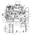
図4〜図9は、DPF1を排気マニホールド71の前方に配置した第1実施形態を示している。図4及び図6〜図8に示す如く、ディーゼルエンジン70におけるシリンダヘッド72の正面側に排気マニホールド71が配置されている。シリンダヘッド72の背面側には吸気マニホールド73が配置されている。シリンダヘッド72は、エンジン出力軸74(クランク軸、図7及び図8参照)とピストン(図示省略)を有するシリンダブロック75に上載されている。シリンダブロック75の左右両側面からエンジン出力軸74の左右先端部をそれぞれ突出させている。
(5-1). First Embodiment FIGS. 4 to 9 show a first embodiment in which the DPF 1 is disposed in front of the exhaust manifold 71. As shown in FIGS. 4 and 6 to 8, an exhaust manifold 71 is arranged on the front side of the cylinder head 72 in the diesel engine 70. An intake manifold 73 is disposed on the back side of the cylinder head 72. The cylinder head 72 is mounted on a cylinder block 75 having an engine output shaft 74 (crank shaft, see FIGS. 7 and 8) and a piston (not shown). The left and right tip portions of the engine output shaft 74 protrude from the left and right side surfaces of the cylinder block 75, respectively.

図4〜図7に示す如く、シリンダブロック75の左側面にフライホイールハウジング78を固着している。フライホイールハウジング78内にフライホイール79を設ける。エンジン出力軸74の左先端側にフライホイール79を軸支させている。作業車両(バックホウ100やフォークリフト120等)の作動部に、フライホイール79を介してディーゼルエンジン70の動力を取り出すように構成している。   As shown in FIGS. 4 to 7, a flywheel housing 78 is fixed to the left side surface of the cylinder block 75. A flywheel 79 is provided in the flywheel housing 78. A flywheel 79 is pivotally supported on the left end side of the engine output shaft 74. The power of the diesel engine 70 is taken out via the flywheel 79 to the working part of the work vehicle (backhoe 100, forklift 120, etc.).

また、シリンダブロック75の下面にはオイルパン95が配置されている。オイルパン95内には潤滑油が貯留されている。オイルパン95内の潤滑油は、シリンダブロック75内における背面寄りの部位に配置されたオイルポンプ156にて吸引され、シリンダブロック75の背面に配置されたオイルクーラ163(図5及び図8参照)並びにオイルフィルタ157を介して、ディーゼルエンジン70の各潤滑部に供給される。各潤滑部に供給された潤滑油は、その後オイルパン95に戻される。オイルポンプ156はエンジン出力軸74の回転にて駆動するように構成されている。オイルクーラ163は冷却水にて潤滑油を冷却するためのものである。シリンダブロック75の背面に、オイルクーラ163を介してオイルフィルタ157が取り付けられている(シリンダブロック75の背面とオイルフィルタ157との間にオイルクーラ163が介設されている)。第1実施形態では、エンジン出力軸74を挟んで吸気マニホールド73側にオイルクーラ163が、排気マニホールド71側に後述するEGRクーラ147が配置されている。   An oil pan 95 is arranged on the lower surface of the cylinder block 75. Lubricating oil is stored in the oil pan 95. Lubricating oil in the oil pan 95 is sucked by an oil pump 156 disposed in a portion near the back surface in the cylinder block 75, and an oil cooler 163 disposed in the back surface of the cylinder block 75 (see FIGS. 5 and 8). In addition, the oil is supplied to each lubricating portion of the diesel engine 70 via the oil filter 157. The lubricating oil supplied to each lubricating part is then returned to the oil pan 95. The oil pump 156 is configured to be driven by rotation of the engine output shaft 74. The oil cooler 163 is for cooling the lubricating oil with cooling water. An oil filter 157 is attached to the back surface of the cylinder block 75 via an oil cooler 163 (the oil cooler 163 is interposed between the back surface of the cylinder block 75 and the oil filter 157). In the first embodiment, an oil cooler 163 is disposed on the intake manifold 73 side with an engine output shaft 74 interposed therebetween, and an EGR cooler 147 described later is disposed on the exhaust manifold 71 side.

シリンダブロック75の背面のうちオイルフィルタ157の上方(吸気マニホールド73の下方)には、シリンダブロック75内の燃焼室内に燃料を供給するための燃料噴射ポンプ158が取り付けられている。燃料噴射ポンプ158は、燃料噴射量を調整するための電子ガバナと燃料フィードポンプとを備えている。燃料フィードポンプの駆動にて、燃料タンク内の燃料が燃料フィルタを介して燃料噴射ポンプ158に送り込まれる。   A fuel injection pump 158 for supplying fuel into the combustion chamber in the cylinder block 75 is attached above the oil filter 157 (below the intake manifold 73) on the back surface of the cylinder block 75. The fuel injection pump 158 includes an electronic governor and a fuel feed pump for adjusting the fuel injection amount. By driving the fuel feed pump, the fuel in the fuel tank is sent to the fuel injection pump 158 via the fuel filter.

シリンダブロック75の左側面前寄りの部位には、冷却水循環用の冷却水ポンプ159が配置されている。冷却水ポンプ159はエンジン出力軸74の回転にて駆動するように構成されている。作業車両に搭載されるラジエータ(図示省略)内の冷却水が、冷却水ポンプ159の上部に設けられたサーモスタットケース160を介して、冷却水ポンプ159に供給される。そして、冷却水ポンプ159の駆動にて、冷却水がシリンダヘッド72及びシリンダブロック75に形成された水冷ジャケット(図示省略)に供給され、ディーゼルエンジン70を冷却する。ディーゼルエンジン70の冷却に寄与した冷却水はラジエータ(図示省略)に戻される。   A cooling water pump 159 for circulating cooling water is disposed in a portion of the cylinder block 75 near the front of the left side surface. The cooling water pump 159 is configured to be driven by rotation of the engine output shaft 74. Cooling water in a radiator (not shown) mounted on the work vehicle is supplied to the cooling water pump 159 via a thermostat case 160 provided on the top of the cooling water pump 159. Then, by driving the cooling water pump 159, cooling water is supplied to a water cooling jacket (not shown) formed in the cylinder head 72 and the cylinder block 75 to cool the diesel engine 70. The cooling water that has contributed to the cooling of the diesel engine 70 is returned to the radiator (not shown).

シリンダブロック75の前後両側面とフライホイールハウジング78の前後両側面とには、機関脚取付け部96がそれぞれ設けられている。各機関脚取付け部96には、防振ゴムを有する機関脚体97がボルト締結されている。ディーゼルエンジン70は、各機関脚体97を介して、作業車両(バックホウ100、フォークリフトカー120)等のエンジン取付けシャーシ81に防振支持されている。   Engine leg mounting portions 96 are provided on both the front and rear side surfaces of the cylinder block 75 and the front and rear side surfaces of the flywheel housing 78, respectively. Each engine leg mounting portion 96 is bolted to an engine leg body 97 having vibration-proof rubber. The diesel engine 70 is supported in an anti-vibration manner on an engine mounting chassis 81 such as a work vehicle (backhoe 100, forklift car 120) via each engine leg 97.

吸気マニホールド73の入口部は、当該吸気マニホールド73の略中央部から上向きに突出している。そして、吸気マニホールド73の入口部は、後述するEGR装置91のコレクタ145を介してエアクリーナ(図示省略)に連結されている。エアクリーナに吸い込まれた新気(外部空気)は、当該エアクリーナにて除塵・浄化されたのち、コレクタ145を介して吸気マニホールド73に送られ、そして、ディーゼルエンジン70の各気筒に供給される。   An inlet portion of the intake manifold 73 protrudes upward from a substantially central portion of the intake manifold 73. And the inlet part of the intake manifold 73 is connected with the air cleaner (illustration omitted) via the collector 145 of the EGR apparatus 91 mentioned later. The fresh air (external air) sucked into the air cleaner is dust-removed and purified by the air cleaner, and then sent to the intake manifold 73 via the collector 145 and supplied to each cylinder of the diesel engine 70.

図5及び図6に示すように、EGR装置91(排気ガス再循環装置)は、ディーゼルエンジン70の排気ガスの一部(排気マニホールド71からのEGRガス)と新気(エアクリーナ88からの外部空気)とを混合させて吸気マニホールド73に供給するコレクタ(EGR本体ケース)145と、エアクリーナにコレクタ145を連通させる吸気スロットル部材146と、排気マニホールド71にEGRクーラ147を介して接続される還流管路としての再循環排気ガス管148と、再循環排気ガス管148にコレクタ145を連通させるEGRバルブ部材149とを備えている。   As shown in FIGS. 5 and 6, the EGR device 91 (exhaust gas recirculation device) includes a part of exhaust gas of the diesel engine 70 (EGR gas from the exhaust manifold 71) and fresh air (external air from the air cleaner 88). ) Are mixed and supplied to the intake manifold 73, an intake throttle member 146 that causes the collector 145 to communicate with the air cleaner, and a return pipe that is connected to the exhaust manifold 71 via the EGR cooler 147. As a recirculation exhaust gas pipe 148, and an EGR valve member 149 for communicating the collector 145 with the recirculation exhaust gas pipe 148.

すなわち、吸気マニホールド73と新気導入用の吸気スロットル部材146とがコレクタ145を介して接続されている。そして、コレクタ145には、排気マニホールド71から延びる再循環排気ガス管148の出口側が連通している。図6に示すように、コレクタ145は長筒状に形成されている。吸気スロットル部材146は、コレクタ145の長手方向の一端部にボルト締結されている。コレクタ145のうち吸気スロットル部材146と反対側の部位に形成された下向きの開口端部が、吸気マニホールド73の入口部に着脱可能にボルト締結されている。   That is, the intake manifold 73 and the intake air intake throttle member 146 are connected via the collector 145. The collector 145 communicates with the outlet side of the recirculation exhaust gas pipe 148 extending from the exhaust manifold 71. As shown in FIG. 6, the collector 145 is formed in a long cylindrical shape. The intake throttle member 146 is bolted to one end of the collector 145 in the longitudinal direction. A downward opening end formed in a portion of the collector 145 opposite to the intake throttle member 146 is detachably bolted to the inlet portion of the intake manifold 73.

第1実施形態では、再循環排気ガス管148の出口側が、EGRバルブ部材149を介してコレクタ145に連結されている。EGRバルブ部材149は、その内部にあるEGRバルブ(図示省略)の開度を調節することにより、コレクタ145へのEGRガスの供給量を調節するものである。EGRバルブ部材149の外周面から斜め下向きに突出した開口端部がコレクタ145の長手中途部に連結されている。再循環排気ガス管148の入口側は、EGRクーラ147を介して排気マニホールド71に連結されている。   In the first embodiment, the outlet side of the recirculation exhaust gas pipe 148 is connected to the collector 145 via the EGR valve member 149. The EGR valve member 149 adjusts the supply amount of EGR gas to the collector 145 by adjusting the opening degree of an EGR valve (not shown) in the EGR valve member 149. An opening end portion that protrudes obliquely downward from the outer peripheral surface of the EGR valve member 149 is connected to a longitudinal middle portion of the collector 145. The inlet side of the recirculation exhaust gas pipe 148 is connected to the exhaust manifold 71 via an EGR cooler 147.

図5及び図6に示すように、吸気スロットル部材146とEGRバルブ部材149とは、共通のコレクタ145に組み付けられている。換言すると、吸気スロットル部材146、コレクタ145及びEGRバルブ部材149は1つの部材としてユニット化されている。また、吸気スロットル部材146とコレクタ145とEGRバルブ部材149とは、吸気マニホールド73上に位置(露出)している。   As shown in FIGS. 5 and 6, the intake throttle member 146 and the EGR valve member 149 are assembled to a common collector 145. In other words, the intake throttle member 146, the collector 145, and the EGR valve member 149 are unitized as one member. The intake throttle member 146, the collector 145, and the EGR valve member 149 are positioned (exposed) on the intake manifold 73.

上記の構成により、エアクリーナから吸気スロットル部材146を介してコレクタ145内に新気(外部空気)を供給する一方、排気マニホールド71からEGRバルブ149を介してコレクタ145内にEGRガス(排気マニホールド71から排出される排気ガスの一部)を供給する。エアクリーナからの新気と、排気マニホールド71からのEGRガスとが、コレクタ145内で混合された後、コレクタ145内の混合ガスが吸気マニホールド73に供給される。すなわち、ディーゼルエンジン70から排気マニホールド71に排出された排気ガスの一部が、吸気マニホールド73からディーゼルエンジン70に還流されることによって、高負荷運転時の最高燃焼温度が低下し、ディーゼルエンジン70からのNOx(窒素酸化物)の排出量が低減される。   With the above configuration, fresh air (external air) is supplied from the air cleaner to the collector 145 through the intake throttle member 146, while EGR gas (from the exhaust manifold 71 is supplied from the exhaust manifold 71 to the collector 145 through the EGR valve 149. A part of the exhaust gas discharged). After fresh air from the air cleaner and EGR gas from the exhaust manifold 71 are mixed in the collector 145, the mixed gas in the collector 145 is supplied to the intake manifold 73. That is, a part of the exhaust gas discharged from the diesel engine 70 to the exhaust manifold 71 is recirculated from the intake manifold 73 to the diesel engine 70, so that the maximum combustion temperature at the time of high load operation is lowered. NOx (nitrogen oxide) emissions are reduced.

図4及び図6〜図8に示すように、排気マニホールド71の前方にDPF1が配置されている。この場合、排気マニホールド71の出口部はその左端部側から前向き(横向き)に突出している。DPF1における長手方向一端側と長手方向他端側とには、排気ガス入口管16と排気ガス出口管34とがそれぞれ振り分けて突設されている。排気マニホールド71における前向き突出状の出口部が、剛体構造の連結部材86を介して、DPF1の長手方向一端側にある排気ガス入口管16に着脱可能に連結されている。第1実施形態では、排気マニホールド71の出口部、連結部材86及び排気ガス入口管16の排気接続フランジ体17の三者がボルトにて共締めされている。従って、上記したDPF1は、剛体構造の連結部材86を介して高剛性の排気マニホールド71に支持される。   As shown in FIGS. 4 and 6 to 8, the DPF 1 is disposed in front of the exhaust manifold 71. In this case, the outlet portion of the exhaust manifold 71 protrudes forward (laterally) from the left end side. An exhaust gas inlet pipe 16 and an exhaust gas outlet pipe 34 are provided so as to project from one end side in the longitudinal direction and the other end side in the longitudinal direction of the DPF 1. A forward projecting outlet portion of the exhaust manifold 71 is detachably connected to the exhaust gas inlet pipe 16 on one end side in the longitudinal direction of the DPF 1 through a connecting member 86 having a rigid structure. In the first embodiment, the three parts of the outlet portion of the exhaust manifold 71, the connecting member 86, and the exhaust connection flange body 17 of the exhaust gas inlet pipe 16 are fastened together with bolts. Therefore, the above-described DPF 1 is supported by the highly rigid exhaust manifold 71 via the connecting member 86 having a rigid structure.

図4及び図6に示すように、第1実施形態のDPF1は、エンジン出力軸74と平行な方向に延びた姿勢で配置されていて、排気マニホールド71の前方において、排気ガス移動方向がエンジン出力軸74と平行な方向になるように、ディーゼルエンジン70の正面から適宜離して排気マニホールド71と対峙するように配置されている。従って、シリンダヘッド72、排気マニホールド71及び吸気マニホールド73の上面側は露出していて、メンテナンス作業をし易い状態になっている。   As shown in FIGS. 4 and 6, the DPF 1 of the first embodiment is arranged in a posture extending in a direction parallel to the engine output shaft 74, and the exhaust gas movement direction is the engine output in front of the exhaust manifold 71. It is arranged so as to face the exhaust manifold 71 so as to be appropriately separated from the front surface of the diesel engine 70 so as to be parallel to the shaft 74. Therefore, the upper surfaces of the cylinder head 72, the exhaust manifold 71, and the intake manifold 73 are exposed, and maintenance work is easy.

前述の通り、排気マニホールド71の左端部側にある出口部に、連結部材86を介して、DPF1の長手方向一端側にある排気ガス入口管16が連結することによって、DPF1は、ディーゼルエンジン70のエンジン出力軸74方向の左右幅内に収めて配置されている。その結果、ディーゼルエンジン70を吸気マニホールド73側から見ると(図5参照)、DPF1のほとんどがディーゼルエンジン70にて隠れることになる。   As described above, the exhaust gas inlet pipe 16 on one end in the longitudinal direction of the DPF 1 is connected to the outlet portion on the left end side of the exhaust manifold 71 via the connecting member 86, so that the DPF 1 is connected to the diesel engine 70. The engine output shaft 74 is disposed within a lateral width in the direction of the engine output shaft 74. As a result, when the diesel engine 70 is viewed from the intake manifold 73 side (see FIG. 5), most of the DPF 1 is hidden by the diesel engine 70.

図6及び図7に示すように、DPF1の長手方向一端側に位置する座板体9に、支持脚体としての第1脚ブラケット19aの先端側がボルトにて着脱可能に締結されている。第1脚ブラケット19aの基端側は、シリンダヘッド72におけるフライホイールハウジング78上の左側面にボルトにて着脱可能に締結されている。また、図6及び図8に示すように、DPF1の長手方向他端寄りにあるフィルタ側出口フランジ40に、同じく支持脚体としての第2脚ブラケット19bの先端側がボルトにて着脱可能に締結されている。第2脚ブラケット19bの基端側は、シリンダヘッド72における排気マニホールド71側の正面にボルトにて着脱可能に締結されている。   As shown in FIG.6 and FIG.7, the front end side of the 1st leg bracket 19a as a supporting leg body is detachably fastened to the seat board body 9 located in the longitudinal direction one end side of DPF1 with the volt | bolt. The base end side of the first leg bracket 19a is detachably fastened to the left side surface of the cylinder head 72 on the flywheel housing 78 with a bolt. Further, as shown in FIGS. 6 and 8, the front end side of the second leg bracket 19b as a support leg is detachably fastened to the filter side outlet flange 40 near the other end in the longitudinal direction of the DPF 1 with a bolt. ing. The base end side of the second leg bracket 19b is detachably fastened to the front surface of the cylinder head 72 on the exhaust manifold 71 side with a bolt.

排気マニホールド71の出口部とDPF1の排気ガス入口管16との間に介在させた剛体構造の連結部材86は、単に内部に排気ガスの通路を有するだけのものでもよいが、第1実施形態の連結部材86には、ディーゼルエンジン70の排気圧を調節するための排気絞り弁87(図9参照)を内蔵している。スート(すす)がスートフィルタ3に堆積したときに、連結部材86内の排気絞り弁87の作動制御にてディーゼルエンジン70の排気圧を高くして、ディーゼルエンジン70からの排気ガス温度を高温にすることによって、スートフィルタ3に堆積したスート(すす)を燃焼させることができる。その結果、スートが消失し、スートフィルタ3が再生することになる。   The rigid connection member 86 interposed between the outlet portion of the exhaust manifold 71 and the exhaust gas inlet pipe 16 of the DPF 1 may simply have an exhaust gas passage inside. The connecting member 86 incorporates an exhaust throttle valve 87 (see FIG. 9) for adjusting the exhaust pressure of the diesel engine 70. When soot accumulates on the soot filter 3, the exhaust pressure of the diesel engine 70 is increased by the operation control of the exhaust throttle valve 87 in the connecting member 86, and the exhaust gas temperature from the diesel engine 70 is increased. By doing so, the soot deposited on the soot filter 3 can be burned. As a result, the soot disappears and the soot filter 3 is regenerated.

従って、連結部材86に排気絞り弁87を内蔵すると、負荷が小さく排気ガスの温度が低くなり易い作業(スートが堆積し易い作業)を継続して行った場合でも、排気絞り弁87による排気圧の強制上昇にてスートフィルタ3を再生でき、DPF1の排気ガス浄化能力を適正に維持できる。また、スートフィルタ3に堆積したスートを燃やすためのバーナー等も不要になる。更に、ディーゼルエンジン70始動時も、排気絞り弁87の作動制御にてディーゼルエンジン70の排気圧を高くして、ディーゼルエンジン70からの排気ガス温度を高温にすれば、ディーゼルエンジン70の暖機を促進できる。   Therefore, when the exhaust throttle valve 87 is built in the connecting member 86, the exhaust pressure by the exhaust throttle valve 87 is maintained even when an operation in which the load is small and the temperature of the exhaust gas tends to decrease (operation in which soot is likely to accumulate) is continued. Thus, the soot filter 3 can be regenerated by the forced increase, and the exhaust gas purification ability of the DPF 1 can be properly maintained. Further, a burner or the like for burning the soot deposited on the soot filter 3 becomes unnecessary. Further, when the diesel engine 70 is started, if the exhaust pressure of the diesel engine 70 is increased by controlling the operation of the exhaust throttle valve 87 and the exhaust gas temperature from the diesel engine 70 is increased, the diesel engine 70 is warmed up. Can promote.

また、連結部材86はDPF1よりも排気ガス移動方向上流側に位置するので、連結部材86に、排気絞り弁87に代えて、入口側排気ガス圧力センサや入口側排気ガス温度センサ等(いずれも図示省略)を接続するようにしてもよい。DPF1に送られる排気ガス温度を直接高めるためのヒータを、連結部材86に内蔵してもよい。なお、連結部材86の排気ガス移動方向の長さは、排気マニホールド71の出口部とDPF1の排気ガス入口管16との間の距離ができるだけ短くなるように極力短く設定するのが好ましい。   Further, since the connecting member 86 is located upstream of the DPF 1 in the exhaust gas movement direction, the connecting member 86 is replaced with an inlet side exhaust gas pressure sensor, an inlet side exhaust gas temperature sensor, etc. (Not shown) may be connected. A heater for directly increasing the temperature of the exhaust gas sent to the DPF 1 may be built in the connecting member 86. The length of the connecting member 86 in the exhaust gas movement direction is preferably set as short as possible so that the distance between the outlet of the exhaust manifold 71 and the exhaust gas inlet pipe 16 of the DPF 1 is as short as possible.

排気マニホールド71の出口部から、排気ガス入口管16を介してDPF1内に移動した排気ガスは、DPF1にて浄化されたのち、排気ガス出口管34からテールパイプ(図示省略)に移動して、最終的に機外に排出されることになる。   The exhaust gas that has moved from the outlet of the exhaust manifold 71 into the DPF 1 via the exhaust gas inlet pipe 16 is purified by the DPF 1 and then moved from the exhaust gas outlet pipe 34 to the tail pipe (not shown). Eventually it will be discharged out of the machine.

上記の記載並びに図6から明らかなように、エンジン70からの排気ガスを浄化する複数のガス浄化フィルタ2,3及び前記各ガス浄化フィルタ2,3を収容する複数のケース5,21,32を有する排気ガス浄化装置1と、前記エンジン70に前記排気ガス浄化装置1を支持させる支持脚体19a,19bとを備えているエンジン装置であって、前記排気ガス浄化装置1において隣り合う前記ケース21,32同士は、ボルトによって着脱可能に締結するフランジ体25,26,40,41を介して連結されており、前記フランジ体40は、前記支持脚体19bを介して前記エンジンに連結されているから、フランジ体40や支持脚体19bをケース21,32に溶接することなく別体に構成することになる。このため、溶接起因の応力集中や歪の問題を回避できる。ケース21,32に対するフランジ体40及び支持脚体19bの組付け作業性が高い。   As apparent from the above description and FIG. 6, a plurality of gas purification filters 2, 3 for purifying exhaust gas from the engine 70 and a plurality of cases 5, 21, 32 for housing the gas purification filters 2, 3 are provided. The exhaust gas purifying apparatus 1 has an engine device, and support legs 19a and 19b for supporting the exhaust gas purifying device 1 on the engine 70, and the case 21 adjacent in the exhaust gas purifying device 1 is provided. , 32 are connected to each other via flange bodies 25, 26, 40, 41 which are detachably fastened by bolts, and the flange body 40 is connected to the engine via the support leg 19b. Therefore, the flange body 40 and the support leg 19b are configured separately without being welded to the cases 21 and 32. For this reason, the problem of stress concentration and distortion caused by welding can be avoided. Assembling workability of the flange body 40 and the support leg 19b to the cases 21 and 32 is high.

上記の記載並びに図6から明らかなように、前記排気ガス浄化装置1は、その長手方向一端側に設けられた排気ガス入口管16から、前記エンジンの排気ガスを取り込むように構成されており、前記排気ガス浄化装置1の前記排気ガス入口管16が前記エンジン70の排気マニホールド71に連結されている一方、前記排気ガス浄化装置1の長手方向他端側にある前記フランジ体40が、前記エンジン70のシリンダヘッド72に取り付けられた前記支持脚体19bに連結されているから、排気マニホールド71と支持脚体19bとで排気ガス浄化装置1の重心を長手方向両側から挟むようにして、排気ガス浄化装置1を安定支持できる。エンジン70の高剛性部品であるシリンダヘッド72と支持脚体19bとを利用して、排気ガス浄化装置1を高剛性で且つ安定的に支持でき、振動等による排気ガス浄化装置1の損傷を抑制できる。   As is clear from the above description and FIG. 6, the exhaust gas purification device 1 is configured to take in the exhaust gas of the engine from an exhaust gas inlet pipe 16 provided on one end side in the longitudinal direction. While the exhaust gas inlet pipe 16 of the exhaust gas purification device 1 is connected to the exhaust manifold 71 of the engine 70, the flange body 40 on the other end side in the longitudinal direction of the exhaust gas purification device 1 includes the engine. Since the exhaust manifold 71 and the support leg 19b sandwich the center of gravity of the exhaust gas purification device 1 from both sides in the longitudinal direction, the exhaust gas purification device is connected to the support leg 19b attached to the cylinder head 72 of 70. 1 can be stably supported. Using the cylinder head 72 and the support leg 19b, which are high-rigidity parts of the engine 70, the exhaust gas purification device 1 can be supported with high rigidity and stability, and damage to the exhaust gas purification device 1 due to vibration or the like is suppressed. it can.

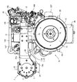
さて、図4及び図6〜図9に示すように、シリンダヘッド73の正面のうち排気マニホールド71の上方には、ディーゼルエンジン70の冷却水を冷媒としてEGRガスを冷却するEGRクーラ147が配置されている。詳細は省略するが、EGRクーラ147は、円筒形の外ケースと、当該外ケース内に設けられた熱交換チューブの複数個とからなる周知の構造である。各熱交換チューブの内部空間がEGRクーラ147(外ケース)のEGRガス入口部168及び出口部169に連通している。   As shown in FIGS. 4 and 6 to 9, an EGR cooler 147 that cools the EGR gas using the cooling water of the diesel engine 70 as a refrigerant is disposed above the exhaust manifold 71 in the front surface of the cylinder head 73. ing. Although details are omitted, the EGR cooler 147 has a known structure including a cylindrical outer case and a plurality of heat exchange tubes provided in the outer case. The internal space of each heat exchange tube communicates with the EGR gas inlet 168 and the outlet 169 of the EGR cooler 147 (outer case).

図6〜図9に示すように、EGRクーラ147のEGRガス入口部168は、筒状のEGRガス取出し管177を介して、排気マニホールド71に連通接続されている。EGRガス出口部169は、再循環排気ガス管148の入口側に連通接続されている。再循環排気ガス管148はシリンダヘッド72の上面側に取り回されていて、その出口側がEGRバルブ部材149を介してコレクタ145に連結されている。EGRクーラ147を通過して適宜冷却されたEGRガスは、EGRガス出口部169から筒状部182内のEGRガス排出管路183を経て再循環排気ガス管148に送り込まれ、吸気マニホールド73側に供給される。   As shown in FIGS. 6 to 9, the EGR gas inlet 168 of the EGR cooler 147 is connected to the exhaust manifold 71 through a cylindrical EGR gas take-out pipe 177. The EGR gas outlet 169 is connected in communication with the inlet side of the recirculation exhaust gas pipe 148. The recirculation exhaust gas pipe 148 is routed on the upper surface side of the cylinder head 72, and the outlet side thereof is connected to the collector 145 via the EGR valve member 149. The EGR gas appropriately cooled after passing through the EGR cooler 147 is sent from the EGR gas outlet 169 to the recirculation exhaust gas pipe 148 via the EGR gas discharge pipe 183 in the cylindrical part 182, and to the intake manifold 73 side. Supplied.

EGRクーラ147(外ケース)には、各熱交換チューブの周囲空間に連通する冷却水入口部170と冷却水出口部171とが設けられている。冷却水入口部170から外ケース内に供給された冷却水にて、各熱交換チューブの周囲を満たすことによって、各熱交換チューブ内を流通するEGRガスが熱交換され、EGRガス温度が低下する。その結果、燃焼時の黒煙(スモーク)の発生を抑制しながら燃焼温度が低く抑えられ、排気ガス中のNOx量低減効果を高めることになる。EGRクーラ147内に供給された冷却水は、冷却水出口部171から排出される。   The EGR cooler 147 (outer case) is provided with a cooling water inlet portion 170 and a cooling water outlet portion 171 that communicate with the surrounding space of each heat exchange tube. By filling the periphery of each heat exchange tube with the cooling water supplied from the cooling water inlet 170 into the outer case, the EGR gas flowing through each heat exchange tube is heat-exchanged, and the EGR gas temperature decreases. . As a result, the combustion temperature is kept low while suppressing the generation of black smoke (smoke) during combustion, and the effect of reducing the amount of NOx in the exhaust gas is enhanced. The cooling water supplied into the EGR cooler 147 is discharged from the cooling water outlet 171.

図9に詳細に示すように、ディーゼルエンジン70の正面側(排気マニホールド71側)には、冷却水ポンプ159からEGRクーラ147に向かう冷却水流通経路172が設けられている。冷却水ポンプ159からの冷却水はディーゼルエンジン70の水冷ジャケット(図示省略)に供給されるだけでなく、一部を冷却水流通経路172に供給するように構成されている。すなわち、冷却水流通経路172は、ディーゼルエンジン70自体への冷却水系統(水冷ジャケットに向かう経路)とは別系統に構成されている。   As shown in detail in FIG. 9, a cooling water flow path 172 from the cooling water pump 159 to the EGR cooler 147 is provided on the front side (exhaust manifold 71 side) of the diesel engine 70. The cooling water from the cooling water pump 159 is configured not only to be supplied to a water cooling jacket (not shown) of the diesel engine 70 but also to supply a part to the cooling water flow path 172. That is, the cooling water flow path 172 is configured as a separate system from the cooling water system (path toward the water cooling jacket) to the diesel engine 70 itself.

この場合、冷却水ポンプ159から排気マニホールド71側(前面側)に突出する冷却水吐出部173(吐出ポートといってもよい)が送りパイプ174を介してEGRクーラ147の冷却水入口部170に連通接続されている。EGRクーラ147の冷却水出口部171は、戻しパイプ176を介してサーモスタットケース160に連通接続されている。従って、冷却水ポンプ159からの冷却水の一部は、EGRクーラ147からサーモスタットケース160に供給され、循環することになる。   In this case, a cooling water discharge portion 173 (also referred to as a discharge port) protruding from the cooling water pump 159 to the exhaust manifold 71 side (front side) is connected to the cooling water inlet portion 170 of the EGR cooler 147 via the feed pipe 174. Communication connection is established. The cooling water outlet 171 of the EGR cooler 147 is connected to the thermostat case 160 through a return pipe 176. Therefore, a part of the cooling water from the cooling water pump 159 is supplied from the EGR cooler 147 to the thermostat case 160 and circulates.

上記の記載並びに図4及び図6〜図8から明らかなように、吸気マニホールド73及び排気マニホールド71を有するディーゼルエンジン70と、ディーゼルエンジン70からの排気ガスを浄化するためのDPF1とを備えている作業車両搭載用のエンジン装置であって、排気マニホールド71の出口部は前方(横向き)に突出しており、DPF1における長手方向一端側と長手方向他端側とに、排気ガス入口管16と排気ガス出口管34とがそれぞれ振り分けて突設されており、排気マニホールド71の出口部に排気ガス入口管16を連結して、DPF1をディーゼルエンジン70の前方(側方)に位置させている。   As is clear from the above description and FIGS. 4 and 6 to 8, the diesel engine 70 having the intake manifold 73 and the exhaust manifold 71 and the DPF 1 for purifying exhaust gas from the diesel engine 70 are provided. The engine device is mounted on a work vehicle, and the outlet of the exhaust manifold 71 projects forward (laterally), and the exhaust gas inlet pipe 16 and the exhaust gas are disposed at one end in the longitudinal direction and the other end in the longitudinal direction of the DPF 1. The outlet pipes 34 are provided so as to be distributed, and the exhaust gas inlet pipe 16 is connected to the outlet portion of the exhaust manifold 71 so that the DPF 1 is positioned in front (side) of the diesel engine 70.

このため、排気マニホールド71にDPF1が至近距離で連通することになり、ディーゼルエンジン70からの排気ガスを、あまり温度低下させることなくDPF1に供給できる。従って、DPF1を適正温度に維持し易く、排気ガス浄化性能が向上する。排気ガス浄化性能が高まることから、ディーゼル酸化触媒2やスートフィルタ3のサイズを小さくすることが可能になり、DPF1の小型化・コンパクト化も図れる。また、排気マニホールド71の出口部に排気ガス入口管16を連結して、DPF1をディーゼルエンジン70の前方(側方)に位置させているから、ディーゼルエンジン70の高剛性部品である排気マニホールド71を利用してDPF1を高剛性に支持でき、振動等によるDPF1の損傷を抑制できる。   For this reason, the DPF 1 communicates with the exhaust manifold 71 at a close distance, and the exhaust gas from the diesel engine 70 can be supplied to the DPF 1 without much temperature decrease. Therefore, it is easy to maintain the DPF 1 at an appropriate temperature, and the exhaust gas purification performance is improved. Since the exhaust gas purification performance is improved, the size of the diesel oxidation catalyst 2 and the soot filter 3 can be reduced, and the DPF 1 can be reduced in size and size. Further, since the exhaust gas inlet pipe 16 is connected to the outlet of the exhaust manifold 71 and the DPF 1 is positioned in front (side) of the diesel engine 70, the exhaust manifold 71 that is a highly rigid part of the diesel engine 70 is provided. By utilizing this, the DPF 1 can be supported with high rigidity and damage to the DPF 1 due to vibration or the like can be suppressed.

上記の記載並びに図6から明らかなように、排気マニホールド71の出口部とDPF1の排気ガス入口管16との間に、剛体構造の連結部材86を介在させているから、連結部材86の存在にて、排気マニホールド71とDPF1との連結強度を向上できる。従って、排気マニホールド71(連結部材86を含む)にてDPF1を強固に支持できる。   As is apparent from the above description and FIG. 6, the rigid connecting member 86 is interposed between the outlet of the exhaust manifold 71 and the exhaust gas inlet pipe 16 of the DPF 1. Thus, the connection strength between the exhaust manifold 71 and the DPF 1 can be improved. Accordingly, the DPF 1 can be firmly supported by the exhaust manifold 71 (including the connecting member 86).

上記の記載並びに図6〜図8から明らかなように、ディーゼルエンジン70のシリンダヘッド72に、DPF1を支持する第1及び第2脚ブラケット19a,19bを備えており、DPF1は、第1及び第2脚ブラケット19a,19bを介してシリンダヘッド72に連結されていて、排気マニホールド71の前方(側方)に位置しているから、排気マニホールド71並びに第1及び第2脚ブラケット19a,19bを用いた支持によって、DPF1を排気マニホールド71の前方(側方)に高剛性で且つ安定的に連結できる。従って、振動等によるDPF1の損傷防止に高い効果を発揮する。   As is clear from the above description and FIGS. 6 to 8, the cylinder head 72 of the diesel engine 70 includes the first and second leg brackets 19 a and 19 b that support the DPF 1. Since it is connected to the cylinder head 72 via the two-leg brackets 19a and 19b and is located in front (side) of the exhaust manifold 71, the exhaust manifold 71 and the first and second leg brackets 19a and 19b are used. Due to the support, the DPF 1 can be connected to the front (side) of the exhaust manifold 71 with high rigidity and stability. Therefore, it is highly effective in preventing damage to the DPF 1 due to vibration or the like.

また、ディーゼルエンジン70の製造場所でディーゼルエンジン70にDPF1を組み込んで出荷することが可能になるから、ディーゼルエンジン70とDPF1をまとめてコンパクトに構成できるという利点もある。作業車両(バックホウ100、フォークリフトカー120)等のエンジンルームにディーゼルエンジン70を搭載するに当たって、エンジンルーム内で排気マニホールド71の前方側に余裕がある場合に、第1実施形態の構成を採用すれば好適である。   Further, since it is possible to ship the DPF 1 incorporated in the diesel engine 70 at the manufacturing site of the diesel engine 70, there is an advantage that the diesel engine 70 and the DPF 1 can be configured in a compact manner. When the diesel engine 70 is mounted in the engine room of a work vehicle (backhoe 100, forklift car 120), etc., when the front side of the exhaust manifold 71 is provided in the engine room, the configuration of the first embodiment is adopted. Is preferred.

上記の記載並びに図6及び図9から明らかなように、吸気マニホールド73及び排気マニホールド71を有するディーゼルエンジン70と、冷却水循環用の冷却水ポンプ159と、排気マニホールド71から吸気マニホールド73に還流させるEGRガスを冷却するためのEGRクーラ147とを備えている作業車両搭載用のエンジン装置であって、ディーゼルエンジン70の排気マニホールド71側に、冷却水ポンプ159及びEGRクーラ147が配置されており、冷却水ポンプ159とEGRクーラ147とをつなぐ冷却水流通経路172が、ディーゼルエンジン70の排気マニホールド71側に配管されているから、EGRクーラ147に対する冷却水流通経路172が冷却水ポンプ159及びEGRクーラ147のある排気マニホールド71側にまとまることになる。従って、冷却水流通経路172の取り回しが容易になり、組付け作業性の向上に寄与できる。   6 and 9, the diesel engine 70 having the intake manifold 73 and the exhaust manifold 71, the cooling water pump 159 for circulating the cooling water, and the EGR that recirculates from the exhaust manifold 71 to the intake manifold 73. An engine device mounted on a work vehicle including an EGR cooler 147 for cooling gas, and a cooling water pump 159 and an EGR cooler 147 are disposed on the exhaust manifold 71 side of the diesel engine 70, and cooling Since the cooling water flow path 172 that connects the water pump 159 and the EGR cooler 147 is piped to the exhaust manifold 71 side of the diesel engine 70, the cooling water flow path 172 for the EGR cooler 147 is connected to the cooling water pump 159 and the EGR cooler 147. Exhaust manifold It will be settled on the field 71 side. Therefore, the cooling water flow path 172 can be easily routed, which can contribute to an improvement in assembly workability.

上記の記載並びに図6及び図9から明らかなように、EGRクーラ147に対する冷却水流通経路172は、ディーゼルエンジン70自体への冷却水系統(水冷ジャケットに向かう経路)とは別系統に構成されているから、ディーゼルエンジン70の冷却に寄与した(温度が上昇した)後の高温になった冷却水がEGRクーラ147に供給されることがない。従って、冷却水の温度上昇に伴う不具合を防止でき、EGRクーラ147の冷却性能の向上を図れる。その上、平面視において、ディーゼルエンジン70のエンジン出力軸74を挟んで吸気マニホールド73側にオイルクーラ163が配置されており、排気マニホールド71側にEGRクーラ147が配置されているから、EGRクーラ147用の冷却水流通系統とオイルクーラ163用の冷却水流通系統とが、エンジン出力軸74を挟んで前後両側に振り分けられることになる。このため、それぞれの冷却水流通系統の配置が分かり易く、組付け作業性やメンテナンス性を向上できる。   As is clear from the above description and FIGS. 6 and 9, the cooling water flow path 172 for the EGR cooler 147 is configured as a separate system from the cooling water system (path to the water cooling jacket) to the diesel engine 70 itself. Therefore, the cooling water having a high temperature after contributing to the cooling of the diesel engine 70 (the temperature has increased) is not supplied to the EGR cooler 147. Therefore, the malfunction accompanying the temperature rise of cooling water can be prevented, and the cooling performance of the EGR cooler 147 can be improved. In addition, in plan view, the oil cooler 163 is disposed on the intake manifold 73 side with the engine output shaft 74 of the diesel engine 70 interposed therebetween, and the EGR cooler 147 is disposed on the exhaust manifold 71 side. The cooling water distribution system for the oil cooler and the cooling water distribution system for the oil cooler 163 are distributed to both the front and rear sides with the engine output shaft 74 interposed therebetween. For this reason, arrangement | positioning of each cooling water distribution system is easy to understand, and assembly workability | operativity and maintainability can be improved.

上記の記載並びに図6及び図9から明らかなように、ディーゼルエンジン70からの排気ガスを浄化するためのDPF1がディーゼルエンジン70の前方(側方)に配置されており、EGRクーラ147が排気マニホールド71の上面側に配置されているから、EGR装置91関連の部材(再循環排気ガス管148やEGRクーラ147等)に対して、DPF1の搭載位置が邪魔にならず、ディーゼルエンジン70(シリンダヘッド72)の上方空間を利用して、コレクタ145やEGRクーラ147等を配置したり、再循環排気ガス管148をコンパクトに取り回したりできる。従って、更なる組付け作業性やメンテナンス性の向上を図れる。   As is apparent from the above description and FIGS. 6 and 9, the DPF 1 for purifying exhaust gas from the diesel engine 70 is disposed in front (side) of the diesel engine 70, and the EGR cooler 147 is disposed in the exhaust manifold. 71, the mounting position of the DPF 1 does not interfere with the EGR device 91 related members (recirculation exhaust gas pipe 148, EGR cooler 147, etc.), and the diesel engine 70 (cylinder head) 72), the collector 145, the EGR cooler 147, and the like can be arranged, and the recirculated exhaust gas pipe 148 can be handled in a compact manner. Therefore, it is possible to further improve the assembly workability and maintainability.

(5−2).第2実施形態
図10及び図11は、DPF1をフライホイールハウジング78の上方に配置した第2実施形態を示している。第2実施形態は、DPF1をフライホイールハウジング78の上方に配置したという点において、第1実施形態と相違しているだけであり、その他の構成は第1実施形態と同じである。
(5-2). Second Embodiment FIGS. 10 and 11 show a second embodiment in which the DPF 1 is arranged above the flywheel housing 78. The second embodiment is different from the first embodiment only in that the DPF 1 is disposed above the flywheel housing 78, and the other configurations are the same as those of the first embodiment.

すなわち、第2実施形態では、排気マニホールド71の出口部がその左端部側から左向き(横向き)に突出している。排気マニホールド71における左向き突出状の出口部が、剛体構造の連結部材86を介して、DPF1の長手方向一端側にある排気ガス入口管16に着脱可能に連結されている。排気マニホールド71の出口部、連結部材86及び排気ガス入口管16の排気接続フランジ体17の三者はボルトにて共締めされている。   That is, in the second embodiment, the outlet portion of the exhaust manifold 71 protrudes leftward (laterally) from the left end side. A leftward projecting outlet portion of the exhaust manifold 71 is detachably connected to the exhaust gas inlet pipe 16 on one end side in the longitudinal direction of the DPF 1 via a connecting member 86 having a rigid structure. The outlet manifold 71, the connecting member 86, and the exhaust connection flange body 17 of the exhaust gas inlet pipe 16 are fastened together with bolts.

図10及び図11に示すように、第2実施形態のDPF1は、エンジン出力軸74と直交する方向に延びた姿勢で配置されていて、フライホイールハウジング78の上方において、排気ガス移動方向がエンジン出力軸74と直交する方向になるように、ディーゼルエンジン70の左側面から適宜離してシリンダヘッド72と対峙するように配置されている。従って、第2実施形態の場合も、シリンダヘッド72、排気マニホールド71及び吸気マニホールド73の上面側は露出していて、メンテナンス作業をし易い状態になっている。   As shown in FIGS. 10 and 11, the DPF 1 of the second embodiment is arranged in a posture extending in a direction orthogonal to the engine output shaft 74, and the exhaust gas movement direction is above the flywheel housing 78. The cylinder head 72 is arranged so as to face the cylinder head 72 so as to be appropriately separated from the left side surface of the diesel engine 70 so as to be perpendicular to the output shaft 74. Therefore, also in the case of the second embodiment, the upper surfaces of the cylinder head 72, the exhaust manifold 71, and the intake manifold 73 are exposed, so that maintenance work can be easily performed.

図10及び図11に示すように、DPF1の長手方向中央部に、支持脚体としての第3脚ブラケット19cの先端側が溶接等にて固定されている。第3脚ブラケット19cの基端側は、フライホイールハウジング78のDPF取付け部82に上方からのボルトにて着脱可能に締結されている。   As shown in FIGS. 10 and 11, the distal end side of the third leg bracket 19 c as a support leg is fixed to the center in the longitudinal direction of the DPF 1 by welding or the like. The base end side of the third leg bracket 19c is detachably fastened to the DPF attachment portion 82 of the flywheel housing 78 with a bolt from above.

第2実施形態のように構成した場合も、排気マニホールド71にDPF1が至近距離で連通することになるから、第1実施形態と同様の作用効果を奏することができる。特に第2実施形態では、ディーゼルエンジン70におけるフライホイールハウジング78の上部に、DPF1を支持する支持脚体としての第3脚ブラケット19cを備えており、DPF1は、第3脚ブラケット19cを介してフライホイールハウジング78に連結されていて、フライホイールハウジング78の上方に位置しているから、排気マニホールド71(連結部材86を含む)並びに第3脚ブラケット19cbを用いた支持によって、DPF1をフライホイールハウジング78の上方(ディーゼルエンジン70の側方)に高剛性で且つ安定的に連結できる。従って、第2実施形態の構成でも、振動等によるDPF1の損傷防止に高い効果を発揮する。作業車両(バックホウ100、フォークリフトカー120)等のエンジンルームにディーゼルエンジン70を搭載するに当たって、エンジンルーム内でフライホイールハウジング78の上方側に余裕がある場合に、第2実施形態の構成を採用すれば好適である。   Even when configured as in the second embodiment, since the DPF 1 communicates with the exhaust manifold 71 at a very short distance, the same operational effects as in the first embodiment can be achieved. In particular, in the second embodiment, the third leg bracket 19c as a support leg for supporting the DPF 1 is provided on the upper part of the flywheel housing 78 in the diesel engine 70, and the DPF 1 is connected to the flywheel via the third leg bracket 19c. Since it is connected to the wheel housing 78 and located above the flywheel housing 78, the DPF 1 is supported by the flywheel housing 78 by support using the exhaust manifold 71 (including the connecting member 86) and the third leg bracket 19 cb. Can be stably connected with high rigidity (side of the diesel engine 70). Therefore, the configuration of the second embodiment also exhibits a high effect in preventing damage to the DPF 1 due to vibration or the like. When the diesel engine 70 is mounted in the engine room of a work vehicle (backhoe 100, forklift car 120) or the like, the configuration of the second embodiment is employed when there is a margin above the flywheel housing 78 in the engine room. Is preferable.

(5−3).第3実施形態
図12は、DPF1の排気ガス入口管16を排気マニホールド71の出口部に直結した第3実施形態を示している。第3実施形態は、DPF1をフライホイールハウジング78の上方に配置したという点において、第2実施形態と同様であるが、連結部材86を省いて、DPF1の排気ガス入口管16を排気マニホールド71の出口部に直結した点において、第2実施形態と相違している。それ以外構成は第1及び第2実施形態と同じである。第3実施形態のように構成した場合も、排気マニホールド71にDPF1が至近距離で連通することになるから、第1及び第2実施形態と同様の作用効果が得られるのである。なお、第1実施形態の構成において、連結部材86を省略してDPF1の排気ガス入口管16を排気マニホールド71の出口部に直結してもよいことは言うまでもない。
(5-3). Third Embodiment FIG. 12 shows a third embodiment in which the exhaust gas inlet pipe 16 of the DPF 1 is directly connected to the outlet portion of the exhaust manifold 71. The third embodiment is the same as the second embodiment in that the DPF 1 is disposed above the flywheel housing 78, but the connecting member 86 is omitted and the exhaust gas inlet pipe 16 of the DPF 1 is connected to the exhaust manifold 71. The second embodiment is different from the second embodiment in that it is directly connected to the outlet. Other configurations are the same as those of the first and second embodiments. Even when configured as in the third embodiment, since the DPF 1 communicates with the exhaust manifold 71 at a close distance, the same operational effects as those of the first and second embodiments can be obtained. In the configuration of the first embodiment, it goes without saying that the connecting member 86 may be omitted and the exhaust gas inlet pipe 16 of the DPF 1 may be directly connected to the outlet portion of the exhaust manifold 71.

(5−4).参考例
図13及び図14は、DPF200を排気マニホールド71の上方に配置した参考例を示している。参考例は、DPF200を排気マニホールド71の上方に配置した点、EGRクーラ147を排気マニホールド71の下方に配置した点、及び、DPF200における排気ガス入口管225の形状の点において、第1〜第3実施形態と相違している。その他の構成は第1〜第3実施形態と基本的に同じである。
(5-4). Reference Example FIGS. 13 and 14 show a reference example in which the DPF 200 is disposed above the exhaust manifold 71. In the reference example, the DPF 200 is disposed above the exhaust manifold 71, the EGR cooler 147 is disposed below the exhaust manifold 71, and the shape of the exhaust gas inlet pipe 225 in the DPF 200 is the first to third. This is different from the embodiment. Other configurations are basically the same as those of the first to third embodiments.

すなわち、参考例では、排気マニホールド71の出口部がその中央部から上向きに突出している。排気マニホールド71における上向き突出状の出口部が、剛体構造の連結部材86を介して、DPF200の長手方向中途部にある排気ガス入口管225の下向き開口端部225aに着脱可能に連結されている。排気マニホールド71の出口部、連結部材86及び排気ガス入口管225の連結フランジ体227の三者はボルトにて共締めされている。   That is, in the reference example, the outlet portion of the exhaust manifold 71 protrudes upward from the central portion. An upward projecting outlet portion of the exhaust manifold 71 is detachably connected to a downward opening end portion 225a of the exhaust gas inlet pipe 225 at a midway portion in the longitudinal direction of the DPF 200 via a connecting member 86 having a rigid structure. The outlet flange of the exhaust manifold 71, the connecting member 86, and the connecting flange body 227 of the exhaust gas inlet pipe 225 are fastened together with bolts.

図13に示すように、参考例のDPF200は、エンジン出力軸74と平行な方向に延びた姿勢で配置されていて、排気マニホールド71の上方において排気ガス移動方向がエンジン出力軸74と平行な方向になるように、ディーゼルエンジン70の上部から適宜離してシリンダヘッド72と対峙させて配置されている。DPF200の長手方向一端側に、第4脚ブラケット19dの先端側がボルトにて着脱可能に締結されている。第4脚ブラケット19dの基端側は、シリンダヘッド72におけるフライホイールハウジング78上の左側面にボルトにて着脱可能に締結されている。また、DPF1の長手方向他端側に、第5脚ブラケット19eの先端側がボルトにて着脱可能に締結されている。第5脚ブラケット19eの基端側は、シリンダヘッド72における排気マニホールド71側の正面にボルトにて着脱可能に締結されている。   As shown in FIG. 13, the DPF 200 of the reference example is arranged in a posture extending in a direction parallel to the engine output shaft 74, and the exhaust gas moving direction is parallel to the engine output shaft 74 above the exhaust manifold 71. The cylinder head 72 is disposed so as to be separated from the upper part of the diesel engine 70 as appropriate. The tip end side of the fourth leg bracket 19d is detachably fastened with a bolt to one end side in the longitudinal direction of the DPF 200. The base end side of the fourth leg bracket 19 d is fastened to the left side surface of the cylinder head 72 on the flywheel housing 78 by a bolt. Moreover, the front end side of the 5th leg bracket 19e is fastened to the other end side of DPF1 in the longitudinal direction so that attachment or detachment is possible with the volt | bolt. The base end side of the fifth leg bracket 19e is detachably fastened to the front face of the cylinder head 72 on the exhaust manifold 71 side with a bolt.

図14に示すように、DPF200は、耐熱金属材料製のDPFケーシング201に内蔵した略筒型のフィルタケース202,203に、例えば白金等のディーゼル酸化触媒204とハニカム構造のフィルタ体であるスートフィルタ205とを直列に並べて収容した構造になっている。   As shown in FIG. 14, a DPF 200 includes a soot filter which is a filter body having a honeycomb structure and a diesel oxidation catalyst 204 such as platinum, for example, in a substantially cylindrical filter case 202, 203 built in a DPF casing 201 made of a refractory metal material. 205 is accommodated in series.

DPFケーシング201の長手方向一端側には、ディーゼル酸化触媒103より排気ガス移動上流側の空間に臨む円形の排気ガス取入れ開口226が形成されている。そして、DPFケーシング201の外側面のうち長手方向一端側には、排気ガス取入れ開口226に連通する排気ガス入口管225が溶接固定されている。図14に詳細に示すように、排気ガス入口管225は上向きに開口した半割筒型に形成されている。矩形状の上向き開口端部225bは、排気ガス取入れ開口226を覆い且つDPFケーシング201の長手(前後)方向に延びるようにしてDPFケーシング201の外側面に溶接固定されている。   On one end side in the longitudinal direction of the DPF casing 201, a circular exhaust gas intake opening 226 that faces a space upstream of the exhaust gas movement from the diesel oxidation catalyst 103 is formed. An exhaust gas inlet pipe 225 that communicates with the exhaust gas intake opening 226 is welded and fixed to one end in the longitudinal direction of the outer surface of the DPF casing 201. As shown in detail in FIG. 14, the exhaust gas inlet pipe 225 is formed in a half cylinder shape opened upward. The rectangular upward opening end 225 b is fixed to the outer surface of the DPF casing 201 by welding so as to cover the exhaust gas intake opening 226 and extend in the longitudinal (front-rear) direction of the DPF casing 201.

排気ガス入口管225のうちDPFケーシング201の長手方向中途部に当たる前端側には、排気ガス流入口である下向き開口端部225aが形成されている。下向き開口端部225aの外周部に連結フランジ体227が溶接固定されている。連結フランジ体227は、剛体構造の連結部材86を介して、排気マニホールド71における上向き突出状の出口部に締結されている。排気ガス入口管225の下向き開口端部225aは、DPFケーシング201における長手方向のほぼ中央部に位置している。このため、DPF201の排気ガス移動方向の長さは、排気ガス入口管225の下向き開口端部225aを挟んでほぼ等分される寸法になっている。   A downward opening end 225a that is an exhaust gas inlet is formed on the front end side of the exhaust gas inlet pipe 225 that corresponds to a midway portion of the DPF casing 201 in the longitudinal direction. A connecting flange body 227 is fixed to the outer periphery of the downward opening end 225a by welding. The connection flange body 227 is fastened to an upward projecting outlet portion of the exhaust manifold 71 via a connection member 86 having a rigid structure. The downward opening end 225 a of the exhaust gas inlet pipe 225 is located at the substantially central portion in the longitudinal direction of the DPF casing 201. For this reason, the length of the DPF 201 in the exhaust gas movement direction has a dimension that is substantially equally divided across the downward opening end 225a of the exhaust gas inlet pipe 225.

DPFケーシング201の長手方向他端側には、スートフィルタ205より排気ガス移動下流側の空間に臨む円形の排気ガス排出開口229が形成されている。そして、DPFケーシング201の外側面には、排気ガス排出開口229に連通する排気ガス出口管228が設けられている。排気ガス出口管228はテールパイプや既設の消音部材(共に図示省略)等に接続される。   On the other end side in the longitudinal direction of the DPF casing 201, a circular exhaust gas discharge opening 229 that faces a space downstream of the soot filter 205 and the exhaust gas movement is formed. An exhaust gas outlet pipe 228 communicating with the exhaust gas discharge opening 229 is provided on the outer surface of the DPF casing 201. The exhaust gas outlet pipe 228 is connected to a tail pipe, an existing silencing member (both not shown), and the like.

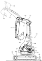
(6).ディーゼルエンジンのバックホウへの搭載構造
図15及び図16を参照して、第1実施形態のディーゼルエンジン70をバックホウ100に搭載した構造を説明する。なお、第2及び第3実施形態並びに参考例のディーゼルエンジン70も、エンジンルームの大きさ・形状が許せば、バックホウ100に搭載可能であることは言うまでもない。
(6). Mounting structure of diesel engine on backhoe A structure in which the diesel engine 70 of the first embodiment is mounted on the backhoe 100 will be described with reference to FIGS. 15 and 16. It goes without saying that the diesel engine 70 of the second and third embodiments and the reference example can also be mounted on the backhoe 100 if the size and shape of the engine room allow.

図15及び図16に示す如く、バックホウ100は、左右一対の走行クローラ103を有する履帯式の走行装置102と、走行装置102上に設けられた旋回機体104とを備えている。旋回機体104は、旋回用油圧モータ(図示省略)によって、360°の全方位にわたって水平旋回可能に構成されている。走行装置102の後部には、対地作業用の土工板105が昇降動可能に装着されている。旋回機体104の左側部には、操縦部106とディーゼルエンジン70とが搭載されている。旋回機体104の右側部には、掘削作業のためのブーム111及びバケット113を有する作業部110が設けられている。   As shown in FIGS. 15 and 16, the backhoe 100 includes a crawler-type traveling device 102 having a pair of left and right traveling crawlers 103, and a turning machine body 104 provided on the traveling device 102. The revolving machine body 104 is configured to be horizontally revolved over 360 ° in all directions by a revolving hydraulic motor (not shown). An earthwork plate 105 for ground work is mounted on the rear part of the traveling device 102 so as to be movable up and down. A steering unit 106 and a diesel engine 70 are mounted on the left side of the revolving machine body 104. A working unit 110 having a boom 111 and a bucket 113 for excavation work is provided on the right side of the revolving machine body 104.

操縦部106には、オペレータが着座する操縦座席108と、ディーゼルエンジン70等を出力操作する操作手段や、作業部110用の操作手段としてのレバー又はスイッチ等が配置されている。作業部110の構成要素であるブーム111には、ブームシリンダ112とバケットシリンダ114とが配置されている。ブーム111の先端部には、掘削用アタッチメントとしてのバケット113が、掬い込み回動可能に枢着されている。ブームシリンダ112又はバケットシリンダ114を作動させて、バケット113によって土工作業(作溝等の対地作業)を実行するように構成している。   The control unit 106 is provided with a control seat 108 on which an operator is seated, operation means for operating the diesel engine 70 and the like, and a lever or switch as an operation means for the work unit 110. A boom cylinder 112 and a bucket cylinder 114 are arranged on a boom 111 which is a component of the working unit 110. A bucket 113 as an attachment for excavation is pivotally attached to the tip end portion of the boom 111 so as to be inserted and rotated. The boom cylinder 112 or the bucket cylinder 114 is operated to perform earthwork work (ground work such as grooving) by the bucket 113.

(7).ディーゼルエンジンのフォークリフトカーへの搭載構造
図17及び図18を参照して、第1実施形態のディーゼルエンジン70をフォークリフトカー120に搭載した構造を説明する。なお、第2及び第3実施形態並びに参考例のディーゼルエンジン70も、エンジンルームの大きさ・形状が許せば、フォークリフトカー120に搭載可能であることは言うまでもない。
(7). Mounting structure of diesel engine on forklift car A structure in which the diesel engine 70 of the first embodiment is mounted on a forklift car 120 will be described with reference to FIGS. 17 and 18. Needless to say, the diesel engine 70 of the second and third embodiments and the reference example can also be mounted on the forklift car 120 if the size and shape of the engine room allow.

図17及び図18に示す如く、フォークリフトカー120は、左右一対の前輪122及び後輪123を有する走行機体124を備えている。走行機体124には、操縦部125とディーゼルエンジン70とが搭載されている。ディーゼルエンジン70はカバー体133にて上方から覆われており、カバー体133上に操縦部125が設けられることになる。   As shown in FIGS. 17 and 18, the forklift car 120 includes a traveling machine body 124 having a pair of left and right front wheels 122 and a rear wheel 123. The traveling body 124 is equipped with a control unit 125 and a diesel engine 70. The diesel engine 70 is covered from above with a cover body 133, and the control unit 125 is provided on the cover body 133.

走行機体124の前部側には、荷役作業のためのフォーク126を有する作業部127が設けられている。走行機体124の後部側には、作業部127との重量バランスを取るためのカウンタウェイト131が設けられている。操縦部125には、オペレータが着座する操縦座席128と、操縦ハンドル129と、ディーゼルエンジン70や作業部127用の操作手段としてのレバー及びスイッチ等が配置されている。   A working unit 127 having a fork 126 for cargo handling work is provided on the front side of the traveling machine body 124. On the rear side of the traveling machine body 124, a counterweight 131 for balancing the weight with the working unit 127 is provided. The control unit 125 is provided with a control seat 128 on which an operator is seated, a control handle 129, levers and switches as operation means for the diesel engine 70 and the working unit 127, and the like.

作業部127の構成要素であるマスト130には、フォーク126が昇降可能に装着されている。フォーク126を昇降動させて、荷物を積んだパレット(図示省略)をフォーク126に上載させ、走行機体124を前後進移動させて、前記パレットの運搬等の荷役作業を実行するように構成している。   A fork 126 is mounted on the mast 130, which is a component of the working unit 127, so as to be movable up and down. The fork 126 is moved up and down, a pallet (not shown) loaded with a load is placed on the fork 126, the traveling machine body 124 is moved forward and backward, and a cargo handling operation such as transportation of the pallet is performed. Yes.

ディーゼルエンジン70は、フライホイールハウジング78が走行機体124の前部側に位置するように配置されている。すなわち、エンジン出力軸74の向きが作業部127とカウンタウェイト131とが並ぶ前後方向に沿うように、ディーゼルエンジン70が配置されている。走行機体124を構成するエンジン取付けシャーシ81に、機関脚体97を介してディーゼルエンジン70が防振支持されている。フライホイールハウジング78の前面側にはミッションケース132が連結されている。ディーゼルエンジン70からフライホイール79を経由した動力は、ミッションケース132にて適宜変速され、前輪122及び後輪123やフォーク126の油圧駆動源に伝達されることになる。   The diesel engine 70 is disposed such that the flywheel housing 78 is located on the front side of the traveling machine body 124. That is, the diesel engine 70 is arranged so that the direction of the engine output shaft 74 is along the front-rear direction in which the working unit 127 and the counterweight 131 are arranged. The diesel engine 70 is supported in an anti-vibration manner via an engine leg 97 on an engine mounting chassis 81 constituting the traveling machine body 124. A mission case 132 is connected to the front side of the flywheel housing 78. The power from the diesel engine 70 via the flywheel 79 is appropriately changed in the transmission case 132 and transmitted to the hydraulic drive sources of the front wheels 122, the rear wheels 123, and the forks 126.

なお、本願発明は、前述の実施形態に限定されるものではなく、様々な態様に具体化できる。例えば本願発明に係るエンジン装置は、前述のようなバックホウ100及びフォークリフトカー120に限らず、コンバイン、トラクタ等の農作業機やクレーン車等の特殊作業用車両のような各種作業車両に対して広く適用できる。また、本願発明における各部の構成は図示の実施形態に限定されるものではなく、本願発明の趣旨を逸脱しない範囲で種々変更が可能である。   In addition, this invention is not limited to the above-mentioned embodiment, It can be embodied in various aspects. For example, the engine device according to the present invention is not limited to the backhoe 100 and the forklift car 120 as described above, but is widely applied to various work vehicles such as agricultural machines such as a combine and a tractor and special work vehicles such as a crane car. it can. Moreover, the structure of each part in this invention is not limited to embodiment of illustration, A various change is possible in the range which does not deviate from the meaning of this invention.

1,200 DPF(ガス浄化フィルタ)
19a〜19e 支持脚体としての脚ブラケット
70 ディーゼルエンジン
71 排気マニホールド
72 シリンダヘッド
73 吸気マニホールド
78 フライホイールハウジング
86 連結部材
91 EGR装置
147 EGRクーラ
148 再循環排気ガス管
163 オイルクーラ
159 冷却水ポンプ
172 冷却水流通経路
177 EGRガス取出し管
1,200 DPF (gas purification filter)
19a to 19e Leg brackets 70 as support legs Diesel engine 71 Exhaust manifold 72 Cylinder head 73 Intake manifold 78 Flywheel housing 86 Connecting member 91 EGR device 147 EGR cooler 148 Recirculated exhaust gas pipe 163 Oil cooler 159 Cooling water pump 172 Cooling Water distribution path 177 EGR gas outlet pipe

Claims (2)

シリンダヘッドのうちエンジン出力軸線と平行な前後一側部に吸気マニホールドを、前後他側部に排気マニホールドを備えているとともに、エンジン出力軸線と直交する左側面に設けたフライホイールハウジングと、前記排気マニホールドから排出される排気ガスの一部を冷却させる排気ガス冷却手段であるEGRクーラと、該EGRクーラと連結して前記排気マニホールドからの排気ガスを前記吸気マニホールドに還流させる排気ガス再循環装置を備えているエンジン装置であって、
前記排気マニホールドからの排気ガスを浄化する複数のガス浄化フィルタ及び前記各ガス浄化フィルタを収容する複数のケースを有する排気ガス浄化装置を備え、
前記排気ガス浄化装置は、前記エンジン出力軸と直行する方向に延びた姿勢で前記フライホイールハウジングの上方に支持脚体を介して着脱可能に連結されるとともに、その長手方向一端側と他端側とに、排気ガス入口管と排気ガス出口管とがそれぞれ振り分けて突設され、前記排気ガス入口管が前記排気マニホールドの排気出口と連結されており、
前記シリンダヘッドの一側部に前記排気ガス再循環装置が設置される一方で、前記シリンダヘッドの他側部に前記EGRクーラの本体ケースが設置され、前記排気ガス再循環装置の本体ケースに連結される排気ガス管は前記シリンダヘッドの上面を跨ぐように取り回されて前記EGRクーラの出口側と連結されていることを特徴とする、
エンジン装置。
The cylinder head is provided with an intake manifold on one front and rear side parallel to the engine output axis, and an exhaust manifold on the other front and rear sides, and a flywheel housing provided on the left side perpendicular to the engine output axis, the exhaust An EGR cooler that is an exhaust gas cooling means for cooling a part of the exhaust gas discharged from the manifold, and an exhaust gas recirculation device that is connected to the EGR cooler and returns the exhaust gas from the exhaust manifold to the intake manifold. An engine device comprising:
An exhaust gas purification device having a plurality of gas purification filters for purifying exhaust gas from the exhaust manifold and a plurality of cases for housing the gas purification filters;
The exhaust gas purification device is detachably connected to the upper part of the flywheel housing via a support leg in a posture extending in a direction perpendicular to the engine output shaft, and has one end side and the other end side in the longitudinal direction. In addition, an exhaust gas inlet pipe and an exhaust gas outlet pipe are respectively provided in a projecting manner, and the exhaust gas inlet pipe is connected to an exhaust outlet of the exhaust manifold,
The exhaust gas recirculation device is installed on one side of the cylinder head, while the main body case of the EGR cooler is installed on the other side of the cylinder head and is connected to the main body case of the exhaust gas recirculation device The exhaust gas pipe is routed so as to straddle the upper surface of the cylinder head and connected to the outlet side of the EGR cooler.
Engine equipment.
前記シリンダヘッドの一側部において、前記排気ガス再循環装置の本体ケースが前記吸気マニホールドの上方で固定される一方で、前記シリンダヘッドの他側部において、前記EGRクーラが前記排気マニホールドの上方で固定されており、
前記排気マニホールドは、左端部側から左向きに突出して前記排気出口を設けて前記排気ガス浄化装置の排気ガス入口管と連結する一方で、左端部側がU字形状のEGRガス取出し管を介して前記EGRクーラの入口側と連結することを特徴とする、
請求項1に記載したエンジン装置。
In one side of the cylinder head, while the main body case of the exhaust gas recirculation device is fixed above said intake manifold, the other side of the cylinder head, the EGR cooler is above said exhaust manifold Fixed ,
The exhaust manifold protrudes leftward from the left end side to provide the exhaust outlet and is connected to the exhaust gas inlet pipe of the exhaust gas purification device, while the left end side is connected to the exhaust gas via a U-shaped EGR gas take-out pipe. It is connected to the inlet side of the EGR cooler,
The engine device according to claim 1.
JP2015021366A 2015-02-05 2015-02-05 Engine equipment Active JP5989155B2 (en)

Priority Applications (1)

Application Number Priority Date Filing Date Title
JP2015021366A JP5989155B2 (en) 2015-02-05 2015-02-05 Engine equipment

Applications Claiming Priority (1)

Application Number Priority Date Filing Date Title
JP2015021366A JP5989155B2 (en) 2015-02-05 2015-02-05 Engine equipment

Related Parent Applications (1)

Application Number Title Priority Date Filing Date
JP2013101563A Division JP2013189980A (en) 2013-05-13 2013-05-13 Engine device

Publications (2)

Publication Number Publication Date
JP2015083844A JP2015083844A (en) 2015-04-30
JP5989155B2 true JP5989155B2 (en) 2016-09-07

Family

ID=53047540

Family Applications (1)

Application Number Title Priority Date Filing Date
JP2015021366A Active JP5989155B2 (en) 2015-02-05 2015-02-05 Engine equipment

Country Status (1)

Country Link
JP (1) JP5989155B2 (en)

Families Citing this family (1)

* Cited by examiner, † Cited by third party
Publication number Priority date Publication date Assignee Title
KR102658308B1 (en) * 2016-12-26 2024-04-18 엘에스엠트론 주식회사 System for exhaust gas recirculation

Family Cites Families (5)

* Cited by examiner, † Cited by third party
Publication number Priority date Publication date Assignee Title
JP2004011499A (en) * 2002-06-05 2004-01-15 Calsonic Kansei Corp Exhaust manifold
JP4206781B2 (en) * 2003-02-27 2009-01-14 マツダ株式会社 Exhaust manifold structure of engine with exhaust supercharger
JP2007056627A (en) * 2005-08-26 2007-03-08 Hitachi Constr Mach Co Ltd Construction machine
JP2008045491A (en) * 2006-08-17 2008-02-28 Kubota Corp Engine
JP4100451B1 (en) * 2007-03-02 2008-06-11 いすゞ自動車株式会社 Exhaust gas purification method and exhaust gas purification system

Also Published As

Publication number Publication date
JP2015083844A (en) 2015-04-30

Similar Documents

Publication Publication Date Title
JP5653585B2 (en) Engine equipment
JP5324952B2 (en) Engine equipment
JP5328023B2 (en) engine
WO2010050314A1 (en) Engine device for mounting on working vehicle
JP5243224B2 (en) Engine device for work vehicle
EP2960091A1 (en) Engine device
JP2013189980A (en) Engine device
WO2010101018A1 (en) Engine device
JP5243223B2 (en) Engine device for work vehicle
JP5658310B2 (en) Engine device for work vehicle
JP5782219B2 (en) Engine equipment
JP5328024B2 (en) engine
JP5989155B2 (en) Engine equipment
JP5793169B2 (en) Engine device for work vehicle
WO2010071082A1 (en) Engine device
JP6411411B2 (en) Work vehicle
WO2010092857A1 (en) Engine device
JP5636358B2 (en) Engine equipment
JP5328022B2 (en) Engine device for work vehicle
JP2010106695A (en) Engine device for mounting on working vehicle
WO2010090069A1 (en) Egr device and engine device with same
JP2014088878A (en) Engine device loaded in work vehicle
JP6181631B2 (en) Engine device for work vehicle
JP5450865B2 (en) Engine device for work vehicle
JP5872301B2 (en) Exhaust gas purification device

Legal Events

Date Code Title Description
A621 Written request for application examination

Free format text: JAPANESE INTERMEDIATE CODE: A621

Effective date: 20150205

A977 Report on retrieval

Free format text: JAPANESE INTERMEDIATE CODE: A971007

Effective date: 20151228

A131 Notification of reasons for refusal

Free format text: JAPANESE INTERMEDIATE CODE: A131

Effective date: 20160120

A521 Written amendment

Free format text: JAPANESE INTERMEDIATE CODE: A523

Effective date: 20160310

TRDD Decision of grant or rejection written
A01 Written decision to grant a patent or to grant a registration (utility model)

Free format text: JAPANESE INTERMEDIATE CODE: A01

Effective date: 20160727

A61 First payment of annual fees (during grant procedure)

Free format text: JAPANESE INTERMEDIATE CODE: A61

Effective date: 20160809

R150 Certificate of patent or registration of utility model

Ref document number: 5989155

Country of ref document: JP

Free format text: JAPANESE INTERMEDIATE CODE: R150

R250 Receipt of annual fees

Free format text: JAPANESE INTERMEDIATE CODE: R250

S533 Written request for registration of change of name

Free format text: JAPANESE INTERMEDIATE CODE: R313533

R350 Written notification of registration of transfer

Free format text: JAPANESE INTERMEDIATE CODE: R350