JP5986867B2 - Tsunami shelter - Google Patents

Tsunami shelter Download PDF

Info

Publication number
JP5986867B2
JP5986867B2 JP2012219567A JP2012219567A JP5986867B2 JP 5986867 B2 JP5986867 B2 JP 5986867B2 JP 2012219567 A JP2012219567 A JP 2012219567A JP 2012219567 A JP2012219567 A JP 2012219567A JP 5986867 B2 JP5986867 B2 JP 5986867B2
Authority
JP
Japan
Prior art keywords
sphere
tsunami
buoyancy
tsunami shelter
shelter
Prior art date
Legal status (The legal status is an assumption and is not a legal conclusion. Google has not performed a legal analysis and makes no representation as to the accuracy of the status listed.)
Active
Application number
JP2012219567A
Other languages
Japanese (ja)
Other versions
JP2014069778A (en
Inventor
坂本 善正
善正 坂本
Original Assignee
阪神硝子工業株式会社
Priority date (The priority date is an assumption and is not a legal conclusion. Google has not performed a legal analysis and makes no representation as to the accuracy of the date listed.)
Filing date
Publication date
Application filed by 阪神硝子工業株式会社 filed Critical 阪神硝子工業株式会社
Priority to JP2012219567A priority Critical patent/JP5986867B2/en
Publication of JP2014069778A publication Critical patent/JP2014069778A/en
Application granted granted Critical
Publication of JP5986867B2 publication Critical patent/JP5986867B2/en
Active legal-status Critical Current
Anticipated expiration legal-status Critical

Links

Images

Description

本発明は、津波が発生したときに避難する津波用シェルターに関する。   The present invention relates to a tsunami shelter that evacuates when a tsunami occurs.

従来、津波が発生したときに避難するシェルターとして、津波の流れに乗って自由漂流するシェルターが知られている(例えば、特許文献1参照)。特許文献1に記載のシェルターは、自由漂流中に障害物に衝突したときに破損しにくいように、略球体状に形成されている。そして、シェルター内の底部には、自由漂流中の姿勢を安定させるために、錘となるバラスト水を収容する水タンクが形成されている。   Conventionally, a shelter that freely drifts on a tsunami flow is known as a shelter that evacuates when a tsunami occurs (see, for example, Patent Document 1). The shelter described in Patent Document 1 is formed in a substantially spherical shape so that it is not easily damaged when it collides with an obstacle during free drifting. And in the bottom part in a shelter, in order to stabilize the attitude | position in a free drift, the water tank which accommodates the ballast water used as a weight is formed.

特開2004−322939号公報JP 2004-322939 A

従来の前記シェルターは、その内部に錘となる水タンクが形成されているため、シェルターの重心位置は、その全体形状である球体の中心から近い位置に配置されている。このため、前記シェルターは、自由漂流中に障害物に衝突したときにバランスを崩しやすく、シェルター内の天地が逆さまになるように回転することがある。この場合には、シェルター内の避難者は、パニック状態に陥って正常な判断をすることができなくなる危険性がある。また、前記シェルターが自由漂流中に障害物に衝突することによってシェルターの一部が破損すると、その破損した箇所から海水等が浸入し、シェルターが沈んでしまう危険性がある。
本発明はこのような事情に鑑みてなされたものであり、自由漂流中において、姿勢をより安定させることができるとともに、内部に浸水が生じても沈むのを防止することができる津波用シェルターを提供することを目的とする。
Since the conventional shelter has a water tank serving as a weight formed therein, the center of gravity of the shelter is disposed at a position close to the center of the sphere that is the overall shape of the shelter. For this reason, the shelter tends to lose its balance when it collides with an obstacle during free drift, and may rotate so that the top and bottom in the shelter is upside down. In this case, the evacuees in the shelter may panic and be unable to make a normal judgment. In addition, when the shelter collides with an obstacle during free drifting, when a part of the shelter is damaged, seawater or the like may enter from the damaged portion, and the shelter may sink.
The present invention has been made in view of such circumstances, and a tsunami shelter that can stabilize the posture during free drifting and can prevent the sinking even if the inside is flooded. The purpose is to provide.

上記目的を達成するための本発明の津波用シェルターは、津波到来時にその流れに乗って自由漂流する津波用シェルターであって、内部に避難室を有する中空状の球体と、前記自由漂流している状態で前記球体の下方に突出するとともに、その突出端側に錘を有する突出体と、前記自由漂流時に前記球体内が浸水した状態で、前記球体が沈まない浮力を付与する浮力体と、を備えていることを特徴としている。   A tsunami shelter of the present invention for achieving the above object is a tsunami shelter that freely drifts on the flow when a tsunami arrives, and includes a hollow sphere having an evacuation chamber inside, and the free drift A projecting body having a weight on the projecting end side thereof, and a buoyancy body that imparts a buoyancy in which the sphere does not sink in a state where the sphere has been submerged during the free drift, It is characterized by having.

本発明によれば、自由漂流している状態で避難室を有する球体の下方に突出するとともに、その突出端側に錘を有する突出体を備えているため、津波用シェルターの重心位置を、球体の中心から下方に離反させることができる。これにより、津波用シェルターが自由漂流中に障害物に衝突しても、球体内の避難室の天地が逆さまになるように当該球体が回転するのを抑制することができる。したがって、従来の球体内部に錘が配置される場合に比べて、安定した状態で津波用シェルターを自由漂流させることができる。また、自由漂流時に球体内が浸水したときは、浮力体により球体が沈まない浮力が付与されるため、津波用シェルターが沈むのを防止することができる。   According to the present invention, the sphere having the center of gravity of the tsunami shelter is provided with the protruding body having a weight on the protruding end side and protruding below the spherical body having the evacuation chamber in a free drifting state. Can be separated downward from the center. Thereby, even if the tsunami shelter collides with an obstacle during free drifting, the sphere can be prevented from rotating so that the top and bottom of the evacuation chamber in the sphere is upside down. Therefore, the tsunami shelter can be freely drifted in a stable state as compared with the case where the weight is disposed inside the conventional sphere. Further, when the sphere is submerged during free drifting, buoyancy is applied by the buoyancy body so that the sphere does not sink, so that the tsunami shelter can be prevented from sinking.

前記球体には、前記浸水した状態で当該球体の吃水線よりも上方の位置に、外部に脱出可能な脱出口が形成されていることが好ましい。この場合、自由漂流時に球体内が浸水したときに、避難者は脱出口から球体の吃水線よりも上方に避難することができる。これにより、避難者は濡れ続けることを回避しながら球体の外部に避難することができる。   Preferably, the sphere is formed with an outlet that can escape to the outside at a position above the waterline of the sphere in the immersed state. In this case, when the sphere is inundated during free drifting, the evacuees can evacuate from the exit to above the waterline of the sphere. Thereby, the evacuee can evacuate outside the sphere while avoiding being kept wet.

前記球体の外周には、前記浸水した状態で当該球体の吃水線よりも上方の位置に、足載置部が設けられていることが好ましい。この場合、自由漂流時に球体内が浸水したときに、足載置部を、球体の外部に避難した避難者の足場として利用することができるので、避難者が足を滑らせて落下するのを抑制することができる。   It is preferable that a foot placement portion is provided on the outer periphery of the sphere at a position above the waterline of the sphere in the flooded state. In this case, when the sphere is flooded during free drifting, the footrest can be used as a scaffold for refugees who evacuate to the outside of the sphere. Can be suppressed.

前記津波用シェルターは、地面上に横倒しにされた状態で、前記球体側と前記突出体側とが接地した二点接地状態となることが好ましい。この場合、球体側のみが一点接地する場合に比べて、津波用シェルターを安定した状態で接地させることができる。   It is preferable that the tsunami shelter is in a two-point grounding state in which the sphere side and the projecting body side are grounded while being laid down on the ground. In this case, the tsunami shelter can be grounded in a stable state as compared with the case where only the sphere side is grounded at one point.

前記錘は、津波到来時にその流れによって前記突出体が地面上を引きずられながら離陸する程度の重さに設定されていることが好ましい。この場合、津波到来時に、突出体が地面上を引きずられながら離陸することにより、津波用シェルターに対して離陸方向に作用する加速度を低減することもできる。   It is preferable that the weight is set to a weight that allows the protrusion to take off while being dragged on the ground by the flow of the tsunami. In this case, when the tsunami arrives, the projecting body takes off while being dragged on the ground, whereby the acceleration acting on the tsunami shelter in the takeoff direction can be reduced.

前記浮力体は、前記自由漂流している状態で前記球体の赤道よりも径方向外方に突出して形成された球体側浮力部を有していることが好ましい。この場合、球体側浮力部により自由漂流時における津波用シェルターの水平方向の幅寸法が長くなるため、津波用シェルターの重心位置からメタセンタまでの長さ(GM値)を大きくすることができる。これにより、自由漂流中に津波用シェルターが傾いたときに大きな復元力が作用するので、津波用シェルターをさらに安定した状態で自由漂流させることができる。   It is preferable that the buoyancy body has a sphere-side buoyancy portion formed so as to protrude radially outward from the equator of the sphere in the state of free drifting. In this case, the horizontal width dimension of the tsunami shelter at the time of free drifting is increased by the sphere-side buoyancy portion, so that the length (GM value) from the center of gravity of the tsunami shelter to the metacenter can be increased. As a result, a large restoring force acts when the tsunami shelter is tilted during free drift, so that the tsunami shelter can be free drifted in a more stable state.

前記浮力体は、前記球体の内部に配置された球体側浮力部を有していることが好ましい。この場合、球体2の外側は略球状に形成されるため、自由漂流中に球体2の外側に障害物が引っ掛かるのを抑制することができる。これにより、津波用シェルター1が障害物と衝突して破損するのを抑制することができる。   It is preferable that the buoyancy body has a sphere-side buoyancy portion disposed inside the sphere. In this case, since the outside of the sphere 2 is formed in a substantially spherical shape, it is possible to suppress an obstacle from being caught on the outside of the sphere 2 during free drifting. Thereby, it can suppress that the shelter 1 for tsunami collides with an obstacle, and is damaged.

前記浮力体は、複数に分割された分割浮力体を有し、前記各分割浮力体が、前記球体に対して着脱可能に取り付けられていることが好ましい。この場合、球体に対して分割浮力体を着脱することにより、球体に付与する浮力を簡単に調整することができる。   It is preferable that the buoyancy body has a split buoyancy body divided into a plurality of parts, and each of the split buoyancy bodies is detachably attached to the sphere. In this case, the buoyancy imparted to the sphere can be easily adjusted by detaching the split buoyancy body from the sphere.

前記突出体は、有底筒状に形成された突出本体部を有し、前記浮力体の一部が、前記突出本体部内に収容されていることが好ましい。この場合、球体の中心から錘を離反させるための突出本体部を、浮力体の一部を収容する収容体として兼用することができるため、津波用シェルターの構成を簡略化でき、その製造コストを低減することができる。   It is preferable that the protruding body has a protruding main body portion formed in a bottomed cylindrical shape, and a part of the buoyancy body is accommodated in the protruding main body portion. In this case, since the projecting main body for separating the weight from the center of the sphere can be used as a housing for housing a part of the buoyancy body, the configuration of the tsunami shelter can be simplified, and the manufacturing cost can be reduced. Can be reduced.

前記突出体は、前記錘が着脱可能に取り付けられている突出本体部を有していることが好ましい。この場合、津波用シェルターを運搬する際に、錘を突出本体部から取り外すことで、津波用シェルターの運搬作業が容易となる。   It is preferable that the protrusion has a protrusion main body to which the weight is detachably attached. In this case, when the tsunami shelter is transported, the tsunami shelter can be easily transported by removing the weight from the protruding main body.

前記錘は、複数に分割された分割錘からなり、前記各分割錘が、前記突出本体部に対して着脱可能に取り付けられていることが好ましい。この場合、突出本体部に対して分割錘を着脱して、錘全体の重量を調整することにより、津波用シェルターが自由漂流中に障害物に衝突したときに、球体内の避難室の天地が逆さまになるように当該球体が回転するのを抑制することができる。   It is preferable that the weight comprises a plurality of divided weights, and each of the divided weights is detachably attached to the protruding main body. In this case, when the tsunami shelter collides with an obstacle during free drifting, the top and bottom of the evacuation chamber inside the sphere is removed by attaching and detaching the divided weight to the projecting main body and adjusting the weight of the entire weight. The rotation of the sphere so as to be upside down can be suppressed.

前記突出体は、有底筒状に形成された突出本体部を有し、前記突出本体部内にバラスト水が充填されるバラスト室が形成されていることが好ましい。この場合、球体の中心から錘を離反させるための突出本体部を、バラスト水を充填するバラスト室として兼用することができるため、津波用シェルターの構成を簡略化でき、その製造コストを低減することができる。   It is preferable that the projecting body has a projecting main body portion formed in a bottomed cylindrical shape, and a ballast chamber filled with ballast water is formed in the projecting main body portion. In this case, since the protruding main body part for separating the weight from the center of the sphere can be used as a ballast chamber filled with ballast water, the structure of the tsunami shelter can be simplified and the manufacturing cost can be reduced. Can do.

前記津波用シェルターは、前記バラスト室に充填されたバラスト水が、前記錘を兼ねていることが好ましい。この場合、津波用シェルターの構成をさらに簡略化でき、その製造コストを低減することができる。   In the tsunami shelter, it is preferable that ballast water filled in the ballast chamber also serves as the weight. In this case, the structure of the tsunami shelter can be further simplified, and the manufacturing cost can be reduced.

前記突出本体部は、前記球体に対して着脱可能に取り付けられていることが好ましい。この場合、津波用シェルターを運搬する際に、突出本体部を球体から取り外すことで、津波用シェルターを大きく2つに分割することができるので、津波用シェルターの運搬作業が容易となる。   It is preferable that the protruding main body is detachably attached to the sphere. In this case, when the tsunami shelter is transported, the projecting main body portion is removed from the sphere, so that the tsunami shelter can be largely divided into two, so that the tsunami shelter can be transported easily.

前記津波用シェルターは、前記突出本体部が、前記球体の材質よりも比重の大きい材質で形成されていることが好ましい。この場合、突出本体部の重量によって、津波用シェルターの重心位置を、球体の中心からさらに下方に離反させることができる。   In the tsunami shelter, the protruding main body portion is preferably formed of a material having a specific gravity greater than that of the sphere. In this case, the center of gravity position of the tsunami shelter can be moved further away from the center of the sphere by the weight of the projecting main body.

前記津波用シェルターは、不使用時に前記球体が転がり難い状態で当該球体側又は前記突出体側を支持する架台を備えていることが好ましい。この場合、不使用時に架台によって球体側又は突出体側を安定した状態で支持することができる。   It is preferable that the tsunami shelter includes a gantry that supports the sphere side or the protruding body side in a state where the sphere hardly rolls when not in use. In this case, the spherical body side or the projecting body side can be stably supported by the gantry when not in use.

本発明の津波用シェルターによれば、自由漂流中に障害物に衝突しても、球体内の避難室の天地が逆さまになるように当該球体が回転するのを抑制することができるため、従来の球体内部に錘が配置される場合に比べて、安定した状態で津波用シェルターを自由漂流させることができる。また、自由漂流時に球体内が浸水したときには、球体が沈まない浮力が付与されるため、津波用シェルターが沈むのを防止することができる。   According to the tsunami shelter of the present invention, even if it collides with an obstacle during free drifting, it is possible to suppress the sphere from rotating so that the top of the evacuation chamber in the sphere is upside down. The tsunami shelter can be drifted freely in a stable state as compared with the case where the weight is arranged inside the sphere. Further, when the sphere is submerged during free drifting, buoyancy that prevents the sphere from sinking is applied, so that the tsunami shelter can be prevented from sinking.

本発明の第1の実施形態に係る津波用シェルターの側面図である。It is a side view of the tsunami shelter which concerns on the 1st Embodiment of this invention. 上記津波用シェルターの平面図である。It is a top view of the said tsunami shelter. 上記津波用シェルターの断面図である。It is sectional drawing of the said tsunami shelter. 上記津波用シェルターの底面図である。It is a bottom view of the said tsunami shelter. 上記津波用シェルターが浸水した状態を示す側面図である。It is a side view which shows the state where the said tsunami shelter was flooded. 上記津波用シェルターを地面上に横倒しにした状態を示す側面図である。It is a side view which shows the state which laid down the tsunami shelter on the ground. 津波到来時における上記津波用シェルターの動きを示す説明図である。It is explanatory drawing which shows a motion of the said tsunami shelter at the time of tsunami arrival. 本発明の第2の実施形態に係る津波用シェルターを示す断面図である。It is sectional drawing which shows the shelter for tsunami which concerns on the 2nd Embodiment of this invention. 本発明の第3の実施形態に係る津波用シェルターを示す断面図である。It is sectional drawing which shows the shelter for tsunami which concerns on the 3rd Embodiment of this invention. 本発明の第4の実施形態に係る津波用シェルターを示す断面図である。It is sectional drawing which shows the shelter for tsunami which concerns on the 4th Embodiment of this invention. 本発明の第5の実施形態に係る津波用シェルターを示す断面図である。It is sectional drawing which shows the shelter for tsunami which concerns on the 5th Embodiment of this invention. 本発明の第6の実施形態に係る津波用シェルターを示す断面図である。It is sectional drawing which shows the shelter for tsunami which concerns on the 6th Embodiment of this invention. 本発明の第7の実施形態に係る津波用シェルターを示す断面図である。It is sectional drawing which shows the shelter for tsunami which concerns on the 7th Embodiment of this invention. 本発明の第8の実施形態に係る津波用シェルターを示す断面図である。It is sectional drawing which shows the shelter for tsunami which concerns on the 8th Embodiment of this invention. 図14のA−A矢視断面図である。It is AA arrow sectional drawing of FIG. (a)は本発明の第9の実施形態に係る津波用シェルターを示す平面図であり、(b)はその津波用シェルターの側面図である。(A) is a top view which shows the shelter for tsunami which concerns on the 9th Embodiment of this invention, (b) is a side view of the shelter for tsunami. (a)は本発明の第10の実施形態に係る津波用シェルターを示す背面図であり、(b)はその側面図である。(A) is a rear view which shows the tsunami shelter which concerns on the 10th Embodiment of this invention, (b) is the side view.

次に、本発明の好ましい実施形態について添付図面を参照しながら説明する。
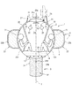
図1は本発明の第1の実施形態に係る津波用シェルターの側面図である。本実施形態の津波用シェルター1は、津波到来時にその流れに乗って自由漂流するものであり、図1は、津波用シェルター1が自由漂流している状態を示している。この津波用シェルター1は、中空状の球体2と、自由漂流している状態で球体2の下方に突出する筒状の突出体3とを備えている。
Next, preferred embodiments of the present invention will be described with reference to the accompanying drawings.
FIG. 1 is a side view of a tsunami shelter according to a first embodiment of the present invention. The tsunami shelter 1 of this embodiment is free drifting on the flow when the tsunami arrives, and FIG. 1 shows a state where the tsunami shelter 1 is free drifting. The tsunami shelter 1 includes a hollow sphere 2 and a cylindrical protrusion 3 that protrudes below the sphere 2 in a free drifting state.

図2は津波用シェルターの平面図であり、図3は津波用シェルターの断面図である。図2及び図3において、前記球体2は、FRP(繊維強化プラスチック)製の複数(3枚)の主殻板20と、各主殻板20の下方に配置された複数(3枚)の内殻板21とによって構成されている。主殻板20は、ハンドレイアップ成形により断面円弧状に湾曲形成されるとともに、平面視において球体2を周方向均等に三分割する大きさに形成されている。内殻板21は、主殻板20と同一の曲率半径にて断面円弧状に湾曲形成されるとともに、平面視において球体2を周方向均等に三分割する大きさに形成されている。球体2は、これら複数の主殻板20及び内殻板21を組み合わせることによって球状に形成されている。   FIG. 2 is a plan view of the tsunami shelter, and FIG. 3 is a cross-sectional view of the tsunami shelter. 2 and 3, the sphere 2 includes a plurality (three) of main shell plates 20 made of FRP (fiber reinforced plastic) and a plurality (three) of the main shell plates 20 arranged below each main shell plate 20. And a shell plate 21. The main shell plate 20 is formed in a curved shape in a circular arc shape by hand lay-up molding, and is formed in a size that equally divides the sphere 2 into three in the circumferential direction in plan view. The inner shell plate 21 is curved and formed in a circular arc shape with the same radius of curvature as the main shell plate 20, and is sized to equally divide the sphere 2 in the circumferential direction in plan view. The spherical body 2 is formed in a spherical shape by combining the plurality of main shell plates 20 and the inner shell plate 21.

図2及び図3において、前記球体2の各主殻板20の下端には、FRP製の複数(3枚)の外殻板22がそれぞれ一体に形成されている。外殻板22は、ハンドレイアップ成形により、内殻板21よりも大きい曲率半径にて断面円弧状に湾曲形成されている。平面視において周方向に隣り合う外殻板22同士は互いに連結されており、全体として内殻板21の全周を覆う環状体6として構成されている。外殻板22は、環状体6を周方向均等に三分割する大きさに形成されている。外殻板22の上端部には、水平方向に延びる足載置部22aが屈曲形成されている。   2 and 3, a plurality of (three) outer shell plates 22 made of FRP are integrally formed at the lower end of each main shell plate 20 of the sphere 2. The outer shell plate 22 is formed into a curved arc shape with a larger radius of curvature than the inner shell plate 21 by hand lay-up molding. The outer shell plates 22 adjacent in the circumferential direction in plan view are connected to each other, and are configured as an annular body 6 that covers the entire circumference of the inner shell plate 21 as a whole. The outer shell plate 22 is formed in such a size that the annular body 6 is equally divided into three in the circumferential direction. A foot placement portion 22a extending in the horizontal direction is bent at the upper end portion of the outer shell plate 22.

図3において、球体2の内部の下側には床面23が設けられており、その上側には避難室2aが形成されている。また、床面23の下側には食料や飲料水等を貯蔵する貯蔵室2bが形成されている。避難室2aには、避難者が着座する複数の座席24が主殻板20の内壁に固定されている。また、避難室2aには、座席24に着座した避難者が把持する複数のポール25が配置されており、各ポール25の長手方向両端部は主殻板20の内壁と床面23とに固定されている。各座席24には、例えば4点式のシートベルト(図示省略)が設けられている。球体2は、その外径が1000〜2000mm(本実施形態では約2000mm)、避難室2aには1〜6人(本実施形態では約6人)の避難者を収容することができるようになっている。   In FIG. 3, a floor surface 23 is provided on the lower side of the sphere 2, and an evacuation chamber 2 a is formed on the upper side thereof. A storage room 2b for storing food, drinking water, and the like is formed below the floor surface 23. In the evacuation chamber 2 a, a plurality of seats 24 on which refugees are seated are fixed to the inner wall of the main shell plate 20. The evacuation chamber 2 a is provided with a plurality of poles 25 held by evacuees seated in the seat 24, and both longitudinal ends of each pole 25 are fixed to the inner wall of the main shell plate 20 and the floor surface 23. Has been. Each seat 24 is provided with, for example, a four-point seat belt (not shown). The sphere 2 has an outer diameter of 1000 to 2000 mm (about 2000 mm in this embodiment), and 1 to 6 people (about 6 people in this embodiment) can be accommodated in the evacuation chamber 2a. ing.

球体2の上部には、津波到来時に避難室2aに出入りするとともに、自由漂流中に球体2の外部へ脱出するための脱出口2cが開口形成されている。この脱出口2cは、後述する第2吃水線W2(図5参照)よりも上方の位置に形成されており、球体2の上部に回動可能に設けられたハッチ蓋26により開閉されるようになっている。ハッチ蓋26は、図2及び図3に示すように、脱出口2cを開閉する円形の蓋本体26aと、この蓋本体26aの外側に回転可能に設けられた外ハンドル26bと、蓋本体26aの内側に回転可能に設けられた内ハンドル26cとを備えている。   In the upper part of the sphere 2, an exit 2 c is formed to enter and exit the evacuation chamber 2 a when a tsunami arrives and to escape to the outside of the sphere 2 during free drift. The escape port 2c is formed at a position above a second floodline W2 (see FIG. 5), which will be described later, and is opened and closed by a hatch lid 26 that is rotatably provided on the top of the sphere 2. It has become. As shown in FIGS. 2 and 3, the hatch lid 26 includes a circular lid body 26a for opening and closing the outlet 2c, an outer handle 26b rotatably provided on the outside of the lid body 26a, and a lid body 26a. And an inner handle 26c rotatably provided inside.

前記外ハンドル26b及び内ハンドル26cは、蓋本体26aを脱出口2cを閉鎖した状態でロック及びロック解除するものであり、外ハンドル26bは球体2の外側から、内ハンドル26cは球体2の内側である避難室2aからそれぞれロック操作及びロック解除操作を行うことができる。球体2の上部には、ハッチ蓋26が自由漂流中に障害物と干渉して破損するのを防止する防護枠27が突設されている。この防護枠27は、図2に示すように、平面視においてハッチ蓋26の外周に沿って環状に形成されている。   The outer handle 26b and the inner handle 26c are for locking and unlocking the lid body 26a with the outlet 2c closed, the outer handle 26b from the outside of the sphere 2 and the inner handle 26c at the inside of the sphere 2. A lock operation and a lock release operation can be performed from a certain evacuation room 2a. At the upper part of the sphere 2, a protective frame 27 is provided so as to prevent the hatch lid 26 from being damaged by interference with an obstacle during free drift. As shown in FIG. 2, the protective frame 27 is formed in an annular shape along the outer periphery of the hatch lid 26 in plan view.

図1及び図2において、球体2の主殻板20の外面には、複数(3個)の吊り上げ部材5が突設されており、この吊り上げ部材5にクレーン等のフックを引っ掛けることにより、津波用シェルター1を吊り上げて移動させることができるようになっている。これにより、津波用シェルター1を例えば図示しないトラックの荷台上に積み込んで移動させることができる。   1 and 2, a plurality (three) of lifting members 5 project from the outer surface of the main shell plate 20 of the sphere 2. By hooking a hook such as a crane on the lifting member 5, a tsunami The shelter 1 can be lifted and moved. Thereby, the tsunami shelter 1 can be loaded and moved on, for example, a truck bed (not shown).

また、球体2の上側には、複数(6個)の窓部28が設けられている。この窓部28は、ポリカーボネート樹脂や強化ガラス板等の透明板材からなり、避難室2a内の避難者が球体2の外側を視認することができるようになっている。また、球体2の窓部28よりも上側には、複数の(12個)の通気口29が形成されている。前記複数の通気口29の一部には、避難室2a内に設置された呼吸装置(図示省略)が接続されている。この呼吸装置は、避難室2a内の避難者が呼吸する際に、球体2の外側から通気口29を介して吸気するとともに、通気口29から球体2の外側へ呼気を排出するためのものである。これにより、避難者は、避難室2a内の空気を使用することなく呼吸することができるため、避難室2a内が自由漂流中に密室状態となった場合に、避難者が酸欠状態になるのを防止することができる。   A plurality (six) of window portions 28 are provided on the upper side of the sphere 2. This window part 28 consists of transparent board | plate materials, such as a polycarbonate resin and a tempered glass board, and the evacuee in the evacuation room 2a can visually recognize the outer side of the spherical body 2. FIG. A plurality of (12) vent holes 29 are formed above the window portion 28 of the sphere 2. A breathing apparatus (not shown) installed in the evacuation chamber 2a is connected to a part of the plurality of vent holes 29. This breathing apparatus is used to inhale air from the outside of the sphere 2 through the vent 29 and to discharge exhaled air from the vent 29 to the outside of the sphere 2 when the evacuees in the evacuation chamber 2a breathe. is there. Thereby, since the refugee can breathe without using the air in the evacuation room 2a, when the inside of the evacuation room 2a becomes a closed room state during free drifting, the refugee is in an oxygen deficient state. Can be prevented.

図4は、津波用シェルターの底面図である。図3及び図4において、前記突出体3は、有底円筒状に形成された突出本体部31と、この突出本体部31の突出端(図3の下端)に外側に露出した状態で着脱可能に取り付けられた錘32とを有している。前記突出本体部31は、その軸線が球体2の鉛直方向の中心線Y上に配置されるように形成されている(図1参照)。また、突出本体部31は、ハンドレイアップ成形により形成されたFRP製の複数(3枚)の主殻板31aを組み合わせて有底円筒状に形成されている。主殻板20は、平面視において突出本体部31を周方向均等に三分割する大きさに形成されている。   FIG. 4 is a bottom view of the tsunami shelter. 3 and 4, the protruding body 3 is detachable with the protruding main body 31 formed in a bottomed cylindrical shape and the protruding end (lower end in FIG. 3) of the protruding main body 31 exposed to the outside. And a weight 32 attached to the. The protruding body 31 is formed such that its axis is arranged on the center line Y in the vertical direction of the sphere 2 (see FIG. 1). The protruding main body 31 is formed in a bottomed cylindrical shape by combining a plurality (three) of main shell plates 31a made of FRP formed by hand layup molding. The main shell plate 20 is formed in a size that equally divides the protruding main body 31 into three parts in the circumferential direction in plan view.

本実施形態の突出本体部31は、その外径が外殻板22の外径の約1/3の長さとなるように、約800mmに設定されている。また、突出本体部31の各主殻板31aは、球体2の各主殻板20及び各外殻板22とともに一体形成されており、主殻板20,31a及び外殻板22の板厚は、いずれも船舶に用いられるFRP製の板部材と同様に、9〜10mmに設定されている。   The protruding main body 31 of the present embodiment is set to about 800 mm so that the outer diameter is about 1 / of the outer diameter of the outer shell plate 22. The main shell plates 31a of the projecting main body 31 are integrally formed with the main shell plates 20 and the outer shell plates 22 of the sphere 2, and the thicknesses of the main shell plates 20, 31a and the outer shell plate 22 are as follows. These are set to 9 to 10 mm, similarly to the plate member made of FRP used for ships.

図3において、前記錘32は、複数に分割された分割錘32aによって構成されている。各分割錘32aは、例えば鉄板によって円板状に形成されており、各分割錘32aを図3の上下方向に積層することにより、全体として下端角部にR部を有する円柱状に形成されている。このように、錘32は下端角部にR部を有する円柱状に形成されているため、突出本体部31の外側に設けられていても、自由漂流中に障害物に引っ掛かるのを抑制することができる。錘32の重さは、後述するように、津波到来時にその流れによって突出本体部31が地面上を引きずられながら離陸(図7(e)参照)する程度の重さに設定されているのが好ましい。   In FIG. 3, the weight 32 is constituted by a divided weight 32a divided into a plurality of parts. Each divided weight 32a is formed in a disk shape by, for example, an iron plate, and is formed in a cylindrical shape having an R portion at the lower end corner as a whole by stacking each divided weight 32a in the vertical direction of FIG. Yes. Thus, since the weight 32 is formed in a columnar shape having the R portion at the lower end corner portion, even when the weight 32 is provided outside the protruding main body portion 31, it is suppressed from being caught by an obstacle during free drifting. Can do. As will be described later, the weight 32 is set to a weight that allows the projecting main body 31 to take off (see FIG. 7E) while being dragged on the ground by the flow of the tsunami. preferable.

突出本体部31内の底部には、鉄製の補強板33が固定されており、この補強板33には、固定ボルト34のねじ部34bが外側(図3の下側)に突出した状態で、当該固定ボルト34の頭部34aが溶接等により固定されている。固定ボルト34のねじ部34bには、各分割錘32aの中心部に貫通形成された挿通孔32a1が挿通された状態で、ナット35が締め付けられている。これにより、ナット35を緩めてねじ部34bから取り外すことで、各分割錘32aを突出本体部31に対して容易に着脱することができる。   An iron reinforcing plate 33 is fixed to the bottom of the protruding main body 31, and the reinforcing plate 33 has a threaded portion 34b of a fixing bolt 34 protruding outward (lower side in FIG. 3). The head 34a of the fixing bolt 34 is fixed by welding or the like. A nut 35 is tightened in the threaded portion 34b of the fixing bolt 34 in a state where an insertion hole 32a1 penetratingly formed in the center portion of each divided weight 32a is inserted. Thereby, each divided weight 32a can be easily attached to and detached from the protruding main body 31 by loosening the nut 35 and removing it from the screw portion 34b.

図3において、津波用シェルター1は、自由漂流時に球体2の避難室2a内が浸水した状態で球体2が沈まない浮力を付与する浮力体4をさらに備えている。浮力体4は、例えば水を吸収しない発泡材(硬質ウレタン、エラストマー等)からなる。本実施形態の浮力体4は、球体2の内殻板21と外殻板22との間に隙間なく収容された球体側浮力部4aと、突出本体部31の内部空間31bに隙間なく収容された突出体側浮力部4bとによって構成されている。前記突出体側浮力部4bは、球体側浮力部4aの下端と連続して一体に形成されている。   In FIG. 3, the tsunami shelter 1 further includes a buoyancy body 4 that imparts buoyancy that prevents the sphere 2 from sinking in a state where the evacuation chamber 2 a of the sphere 2 is submerged during free drifting. The buoyancy body 4 is made of, for example, a foam material (hard urethane, elastomer, etc.) that does not absorb water. The buoyancy body 4 of this embodiment is accommodated in the sphere-side buoyancy part 4a accommodated between the inner shell plate 21 and the outer shell plate 22 of the sphere 2 without any gap and in the internal space 31b of the protruding main body 31 without gap. It is comprised by the protruding body side buoyancy part 4b. The protruding body side buoyancy part 4b is formed integrally with the lower end of the spherical body side buoyancy part 4a.

前記球体側浮力部4aは、図3の上下方向の中央部である球体2の赤道Xよりも径方向外方に突出して環状に形成されている。本実施形態では、例えば、自由漂流中に、道路に設置された電柱に突設されている昇降用のステップボルト(図示省略)が、外殻板22及び内殻板21に突き刺さって避難室2aが浸水することがないように、前記赤道Xにおける球体側浮力部4aの径方向の厚さは、ステップボルトの突出長さ(約130mm)よりも長い寸法(約150〜200mm)に設定されている。   The sphere-side buoyancy portion 4a is formed in an annular shape so as to protrude radially outward from the equator X of the sphere 2 which is the central portion in the vertical direction of FIG. In this embodiment, for example, during free drifting, a step bolt (not shown) for raising and lowering protruding from a utility pole installed on a road pierces the outer shell plate 22 and the inner shell plate 21, and the evacuation chamber 2a. So that the spherical buoyancy part 4a in the equator X has a thickness (about 150 to 200 mm) longer than the protruding length of the step bolt (about 130 mm). Yes.

図5は、津波用シェルター1の避難室2aが浸水した状態を示す側面図である。図1及び図5に示すように、本実施形態の浮力体4は、定員(6人)が乗り込んでいる避難室2aが浸水していない非浸水状態における球体2の第1吃水線W1が、南緯10度〜25度付近となるように球体2に浮力を付与するとともに、定員(6人)が乗り込んでいる避難室2aが浸水している浸水状態における球体2の第2吃水線W2が、北緯25度〜40度付近となるように球体2に浮力を付与するようになっている。これにより、外殻板22の足載置部22aは、避難室2aが浸水した状態において第2吃水線W2よりも上方に位置するようになっている。   FIG. 5 is a side view showing a state where the evacuation room 2a of the tsunami shelter 1 is flooded. As shown in FIG.1 and FIG.5, the buoyancy body 4 of this embodiment has the 1st waterline W1 of the spherical body 2 in the non-immersed state where the evacuation chamber 2a in which a capacity (six persons) is boarding is not flooded. The second submergence line W2 of the sphere 2 in a flooded state in which the evacuation chamber 2a in which a capacity (6 persons) enters is inundated is given buoyancy so that the sphere 2 is in the vicinity of 10 to 25 degrees south latitude. Buoyancy is applied to the sphere 2 so that the latitude is about 25 degrees to 40 degrees north latitude. Thereby, the foot placement part 22a of the outer shell plate 22 is positioned above the second floodline W2 in a state where the evacuation chamber 2a is submerged.

したがって、自由漂流中に脱出口2cから球体2の外部に避難した避難者は、足載置部22aを水に濡れない足場として利用することができる。その際、避難者は、図5の左側に示すように、足載置部22aに足を置いた状態で防護枠27に腰掛けたり、図5の右側に示すように、足載置部22aに足を置いた状態で防護枠27に手を掛けてしゃがみ込んだりすることができる。これにより、球体2の外部に避難した避難者は、安定した姿勢で、かつ水に濡れ続けることを回避しながら救助を待つことができる。なお、防護枠27には、図5の右側に示す避難者が把持する取手を取り付けてもよい。   Therefore, an evacuee who evacuates from the escape port 2c to the outside of the sphere 2 during free drift can use the footrest 22a as a scaffold that does not get wet with water. At that time, as shown on the left side of FIG. 5, the evacuees can sit on the protective frame 27 with their feet placed on the foot placement part 22a, or on the foot placement part 22a as shown on the right side of FIG. It is possible to crouch down by placing a hand on the protective frame 27 with the foot placed. Thereby, the evacuees who evacuated to the outside of the sphere 2 can wait for a rescue in a stable posture and avoiding being kept wet. In addition, you may attach the handle which the evacuee shown to the right side of FIG.

図6は、津波用シェルター1を地面上に横倒しにした状態を示す側面図である。図6に示すように、本実施形態の津波用シェルター1は、不使用時は地面上に横倒しにした状態で保管されている。この状態において、津波用シェルター1は、球体2側である環状体6の外周部のE点と、突出体3側である錘32のR部のF点とが接地した二点接地状態となっている。これにより、球体2及び突出体3は、球体2の中心線Yと地面とが交差するG点を中心として、二点接地状態を維持しながら水平方向に回転可能となっている。これにより、避難者が球体2のハッチ蓋26を開けて避難室2aに出入りする際には、球体2及び突出体3を上記のように回転させることにより、ハッチ蓋26を開閉し易い位置へ移動させることができる。   FIG. 6 is a side view showing a state where the tsunami shelter 1 is laid down on the ground. As shown in FIG. 6, the tsunami shelter 1 of the present embodiment is stored in a laid state on the ground when not in use. In this state, the tsunami shelter 1 is in a two-point grounding state in which the E point on the outer peripheral portion of the annular body 6 on the sphere 2 side and the F point on the R portion of the weight 32 on the protruding body 3 side are grounded. ing. Thereby, the sphere 2 and the protrusion 3 can rotate in the horizontal direction while maintaining a two-point grounding state around the point G where the center line Y of the sphere 2 intersects the ground. Thus, when the refugee opens the hatch cover 26 of the sphere 2 and enters and exits the evacuation chamber 2a, the sphere 2 and the projecting body 3 are rotated as described above, so that the hatch cover 26 can be easily opened and closed. Can be moved.

さらに、図7(a)及び(b)に示すように、津波が到来したときに、球体2の中心線Yが津波の進行方向Zに対して直交する方向に向いている場合には、津波の流れによって環状体6及び球体2が前記G点を中心として約90度回転することにより、図7(c)及び(d)に示すように、前記中心線Yが津波の進行方向Zと同一方向に向くため、津波用シェルター1をスムーズに離陸させことができる。その際、津波用シェルター1は、図7(e)に示すように、突出体3が地面上を引きずられながら徐々に離陸するため、離陸方向に作用する加速度を低減することもできる。また、津波が引いて水位が低下すると、突出体3が地面上を引きずられながら徐々に着陸するため、着陸方向に作用する加速度も低減することができるとともに、津波用シェルター1が引き波によって遠方へ流されるのを抑制することもできる。   Furthermore, as shown in FIGS. 7A and 7B, when a tsunami arrives, if the center line Y of the sphere 2 is oriented in a direction orthogonal to the traveling direction Z of the tsunami, the tsunami As the annular body 6 and the sphere 2 rotate about 90 degrees around the point G by the flow of the center line Y, the center line Y is the same as the tsunami traveling direction Z, as shown in FIGS. Since it faces in the direction, the tsunami shelter 1 can be taken off smoothly. At that time, as shown in FIG. 7E, the tsunami shelter 1 gradually takes off while the projecting body 3 is dragged on the ground, so that the acceleration acting in the takeoff direction can be reduced. Moreover, when the tsunami is pulled and the water level is lowered, the projecting body 3 is gradually landed while being dragged on the ground, so that the acceleration acting in the landing direction can be reduced and the tsunami shelter 1 is moved far away by the pulling wave. It can also be suppressed from being washed away.

以上のように構成された本実施形態の津波用シェルター1によれば、自由漂流している状態で避難室2aを有する球体2の下方に突出するとともに、その突出端側に錘32を有する突出体3を備えているため、津波用シェルター1の重心位置を、球体2の中心から下方に離反させることができる。これにより、津波用シェルター1が自由漂流中に障害物に衝突しても、球体2内の避難室2aの天地が逆さまになるように当該球体2が回転するのを抑制することができる。したがって、従来の球体内部に錘が配置される場合に比べて、安定した状態で津波用シェルター1を自由漂流させることができる。また、自由漂流時に球体2内が浸水したときは、浮力体4により球体2が沈まない浮力が付与されるため、津波用シェルター1が沈むのを防止することができる。   According to the tsunami shelter 1 of the present embodiment configured as described above, it protrudes below the sphere 2 having the evacuation chamber 2a in a free drifting state and has a weight 32 on the protruding end side. Since the body 3 is provided, the center of gravity of the tsunami shelter 1 can be separated downward from the center of the sphere 2. Accordingly, even when the tsunami shelter 1 collides with an obstacle during free drifting, the sphere 2 can be prevented from rotating so that the top and bottom of the evacuation chamber 2a in the sphere 2 is upside down. Therefore, the tsunami shelter 1 can be freely drifted in a stable state as compared with the case where the weight is arranged inside the conventional sphere. Further, when the inside of the sphere 2 is submerged during free drifting, the buoyancy body 4 provides buoyancy that does not cause the sphere 2 to sink, so that the tsunami shelter 1 can be prevented from sinking.

また、球体2には、図5に示すように浸水した状態で球体2の第2吃水線W2よりも上方の位置に、外部に脱出可能な脱出口2cが形成されているため、自由漂流時に球体2内が浸水したときに、避難者は脱出口2cから球体2の第2吃水線W2よりも上方に避難することができる。これにより、避難者は濡れ続けることを回避しながら球体2の外部に避難することができる。
また、自由漂流時に避難室2aが浸水したときに、外殻板22の足載置部22aを、球体2の外部に避難した避難者の足場として利用することができるため、避難者が足を滑らせて落下するのを抑制することができる。
Further, since the sphere 2 is formed with an exit port 2c that can escape to the outside at a position above the second floodline W2 of the sphere 2 in a flooded state as shown in FIG. When the inside of the sphere 2 is submerged, the evacuees can evacuate above the second floodline W2 of the sphere 2 from the exit 2c. Thereby, the evacuee can evacuate to the outside of the sphere 2 while avoiding being kept wet.
Further, when the evacuation chamber 2a is submerged during free drifting, the foot placement part 22a of the outer shell plate 22 can be used as a scaffold for the refugee who evacuates outside the sphere 2, so It can suppress sliding and falling.

また、津波用シェルター1は、地面上に横倒しにされた状態で、球体2側と突出体3側とが接地した二点接地状態となるため、球体2側のみが一点接地する場合に比べて、津波用シェルター1を安定した状態で接地させることができる。
また、錘32は、津波到来時にその流れによって突出体3が地面上を引きずられながら離陸する程度の重さに設定されているため、津波到来時に、突出体3が地面上を引きずられながら離陸することにより、津波用シェルター1に対して離陸方向に作用する加速度を低減することもできる。
In addition, the tsunami shelter 1 is in a two-point grounding state in which the sphere 2 side and the projecting body 3 side are grounded in a state of being laid down on the ground, so that compared to a case where only the sphere 2 side is grounded at one point. The tsunami shelter 1 can be grounded in a stable state.
Further, since the weight 32 is set to a weight that allows the protrusion 3 to take off while being dragged on the ground by the flow when the tsunami arrives, the weight 32 takes off while the protrusion 3 is dragged on the ground. By doing so, the acceleration which acts in the takeoff direction with respect to the tsunami shelter 1 can also be reduced.

また、球体2の赤道X(図5参照)において径方向外方に突出して形成された球体側浮力部4aにより、自由漂流時における津波用シェルター1の水平方向の幅寸法が長くなるため、津波用シェルター1の重心位置からメタセンタまでの長さ(GM値)を大きくすることができる。これにより、自由漂流中に津波用シェルター1が傾いたときに大きな復元力が作用するので、津波用シェルター1をさらに安定した状態で自由漂流させることができる。
また、浮力体4の一部(突出体側浮力部4b)が、突出本体部31内に収容されているため、球体2の中心から錘32を離反させるための突出本体部31を、浮力体4の一部を収容する収容体として兼用することができる。これにより、津波用シェルター1の構成を簡略化でき、その製造コストを低減することができる。
In addition, since the sphere-side buoyancy portion 4a formed so as to protrude radially outward at the equator X (see FIG. 5) of the sphere 2 increases the horizontal width dimension of the tsunami shelter 1 during free drifting, the tsunami The length (GM value) from the center of gravity of the shelter 1 to the metacenter can be increased. Thereby, since a big restoring force acts when the tsunami shelter 1 tilts during free drift, the tsunami shelter 1 can be drifted freely in a more stable state.
Further, since a part of the buoyancy body 4 (projection body side buoyancy part 4 b) is accommodated in the projection body part 31, the projection body part 31 for separating the weight 32 from the center of the sphere 2 is replaced with the buoyancy body 4. It can also be used as a container for accommodating a part of the container. Thereby, the structure of the tsunami shelter 1 can be simplified and the manufacturing cost can be reduced.

また、錘32が突出本体部31に対して着脱可能に取り付けられているため、津波用シェルター1を運搬する際に、錘32を突出本体部31から取り外すことで、津波用シェルター1の運搬作業が容易となる。
また、錘32は、複数に分割された分割錘32aからなり、各分割錘32aが、突出本体部31に対して着脱可能に取り付けられているため、突出本体部31に対して分割錘32aを着脱して、錘32全体の重量を調整することにより、津波用シェルター1が自由漂流中に障害物に衝突したときに、球体2内の避難室2aの天地が逆さまになるように当該球体2が回転するのを抑制することができる。
In addition, since the weight 32 is detachably attached to the projecting main body 31, the transport work of the tsunami shelter 1 is performed by removing the weight 32 from the projecting main body 31 when transporting the tsunami shelter 1. Becomes easy.
In addition, the weight 32 includes a plurality of divided weights 32 a, and each divided weight 32 a is detachably attached to the protruding main body 31, so that the divided weight 32 a is attached to the protruding main body 31. By attaching and detaching and adjusting the weight of the entire weight 32, when the tsunami shelter 1 collides with an obstacle during free drifting, the sphere 2 is turned upside down so that the top and bottom of the escape chamber 2a in the sphere 2 is upside down. Can be prevented from rotating.

図8は、本発明の第2の実施形態に係る津波用シェルターを示す断面図である。図8において、本実施形態の津波用シェルター1は、第1の実施形態の津波用シェルター1の変形例を示すものであり、球体2の避難室2a内において避難者が床面23上に座った状態で腰が浮かないように支持する腰ベルト11が床面23に設けられている。また、避難室2a内には、床面23上に座った避難者が把持する複数のポール25が配置されており、各ポール25の長手方向両端部は、図8の上下方向に対して傾斜した状態で、主殻板20の内壁と床面23とに固定されている。   FIG. 8 is a cross-sectional view showing a tsunami shelter according to the second embodiment of the present invention. In FIG. 8, the tsunami shelter 1 of the present embodiment is a modification of the tsunami shelter 1 of the first embodiment, and an evacuee sits on the floor 23 in the evacuation chamber 2 a of the sphere 2. A waist belt 11 is provided on the floor surface 23 to support the waist so that the waist does not float in the state where the head is lifted. In the evacuation chamber 2a, a plurality of poles 25 held by evacuees sitting on the floor surface 23 are arranged, and both longitudinal ends of each pole 25 are inclined with respect to the vertical direction in FIG. In this state, it is fixed to the inner wall of the main shell plate 20 and the floor surface 23.

さらに、避難室2a内には、避難者が床面23上に座った状態で、例えば避難者の頭部や胴部をその左右両側から挟み込んで保護するためのプロテクタ(図示省略)が、主殻板20の内壁に取り付けられている。球体2の外径は、運搬時にトラックの荷台上に球体2を積み込めるように、その荷台の幅寸法以下に設定されているのが好ましい。本実施形態の球体2の外径は、軽トラックの荷台上に球体2を積み込めるように、約1400mmに設定されており、避難室2aには3人の避難者を収容することができるようになっている。本実施形態のその他の構成については第1の実施形態と同様であるため、その説明を省略する。   Further, in the evacuation chamber 2a, a protector (not shown) for protecting the refugee by sandwiching the refugee's head and torso from both the left and right sides while the refugee is sitting on the floor 23 is mainly used. It is attached to the inner wall of the shell plate 20. It is preferable that the outer diameter of the sphere 2 is set to be equal to or less than the width of the cargo bed so that the sphere 2 can be loaded on the truck bed during transportation. The outer diameter of the sphere 2 according to the present embodiment is set to about 1400 mm so that the sphere 2 can be loaded on the loading platform of the light truck, and the evacuation chamber 2a can accommodate three evacuees. It has become. Since other configurations of the present embodiment are the same as those of the first embodiment, description thereof is omitted.

本実施形態の津波用シェルター1においても、津波用シェルター1の重心位置を、球体2の中心から下方に離反させることができるため、津波用シェルター1が自由漂流中に障害物に衝突しても、球体2内の避難室2aの天地が逆さまになるように当該球体2が回転するのを抑制することができる。また、自由漂流時に球体2内が浸水したときは、浮力体4により球体2が沈まない浮力が付与されるため、津波用シェルター1が沈むのを防止することができる。   Also in the tsunami shelter 1 of the present embodiment, the center of gravity position of the tsunami shelter 1 can be separated downward from the center of the sphere 2, so that even if the tsunami shelter 1 collides with an obstacle during free drifting Rotation of the sphere 2 can be suppressed so that the top and bottom of the evacuation chamber 2a in the sphere 2 is upside down. Further, when the inside of the sphere 2 is submerged during free drifting, the buoyancy body 4 provides buoyancy that does not cause the sphere 2 to sink, so that the tsunami shelter 1 can be prevented from sinking.

図9は、本発明の第3の実施形態に係る津波用シェルターを示す断面図である。図9において、本実施形態の津波用シェルター1は、第2の実施形態の津波用シェルター1の変形例を示すものであり、球体2の避難室2aにドーナツ状の浮き袋12が設けられている。この浮き袋12は、図示しないガスボンベから例えば二酸化炭素ガスが供給されることにより瞬時に膨張するものであり、通常時は図9の二点鎖線で示すように、萎んだ状態で床面23上に載置されている。これにより、避難室2a内が浸水したときは、浮き袋12を瞬時に膨張させることにより、球体2に浮力を付与することができる。また、避難者は、図示のように、ハッチ蓋26を開放することで、膨張した浮き袋12上に座った楽な姿勢で救助を待つことができる。本実施形態のその他の構成については第2の実施形態と同様であるため、その説明を省略する。   FIG. 9 is a cross-sectional view showing a tsunami shelter according to the third embodiment of the present invention. In FIG. 9, the tsunami shelter 1 of the present embodiment is a modification of the tsunami shelter 1 of the second embodiment, and a donut-shaped floating bag 12 is provided in the evacuation chamber 2 a of the sphere 2. . For example, carbon dioxide gas is supplied from a gas cylinder (not shown) to inflate the floating bag 12 instantaneously. Normally, as shown by a two-dot chain line in FIG. 9, the floating bag 12 is deflated on the floor surface 23. It is placed. Thereby, when the inside of the evacuation chamber 2a is submerged, buoyancy can be imparted to the sphere 2 by inflating the floating bag 12 instantaneously. Further, as shown in the figure, the evacuees can wait for rescue with an easy posture sitting on the inflated float 12 by opening the hatch lid 26. Since other configurations of the present embodiment are the same as those of the second embodiment, description thereof is omitted.

本実施形態の津波用シェルター1によれば、避難室2aに設けられた浮き袋12により球体2に浮力を付与することができるため、浮力体4の浮力が不足する場合に、浮き袋12によって球体2に付与する浮力を増すことができる。また、避難室2aが浸水したときに浮き袋12を常に使用する場合には、浮き袋12の浮力分だけ浮力体4を小さくことができるため、津波用シェルター1全体を小型化することができる。   According to the tsunami shelter 1 of the present embodiment, the buoyancy can be imparted to the sphere 2 by the floating bag 12 provided in the evacuation chamber 2a. The buoyancy imparted to can be increased. Further, when the float bag 12 is always used when the evacuation chamber 2a is submerged, the buoyancy body 4 can be reduced by the buoyancy of the float bag 12, so that the entire tsunami shelter 1 can be downsized.

図10は、本発明の第4の実施形態に係る津波用シェルターを示す断面図である。図10において、本実施形態の津波用シェルター1は、球体2と、この球体2に対して着脱可能に取り付けられた突出体3と、球体2側に設けられた浮力体4とによって構成されている。   FIG. 10 is a sectional view showing a tsunami shelter according to the fourth embodiment of the present invention. In FIG. 10, the tsunami shelter 1 according to the present embodiment includes a sphere 2, a protrusion 3 that is detachably attached to the sphere 2, and a buoyancy body 4 provided on the sphere 2 side. Yes.

球体2は、FRP製の複数(3枚)の主殻板20と、各主殻板20の下方に配置された複数(3枚)の内殻板21と、FRP製の複数(3枚)の外殻板22とによって構成されている。具体的には、主殻板20及び内殻板21は、ハンドレイアップ成形により互いに同一の曲率半径にて断面円弧状に湾曲形成されている。外殻板22の上端部には、内殻板21の径方向外方に大きく膨らんだ膨出部22bが、各主殻板20の下端に一体に形成されている。膨出部22bは、自由漂流中に送電線などの障害物に引っ掛かりにくいように、球体2の赤道Xを中心として断面略半円状に形成されている。また、周方向に隣り合う膨出部22b同士は互いに連結されており、全体として内殻板21の全周を覆う環状体6として構成されている。   The sphere 2 includes a plurality of (three) main shell plates 20 made of FRP, a plurality (three) inner shell plates 21 disposed below each main shell plate 20, and a plurality (three) of FRP. And the outer shell plate 22. Specifically, the main shell plate 20 and the inner shell plate 21 are curved and formed in a cross-sectional arc shape with the same curvature radius by hand lay-up molding. At the upper end portion of the outer shell plate 22, a bulging portion 22 b swelled greatly outward in the radial direction of the inner shell plate 21 is formed integrally with the lower end of each main shell plate 20. The bulging portion 22b is formed in a substantially semicircular cross section around the equator X of the sphere 2 so as not to be caught by an obstacle such as a power transmission line during free drift. Further, the bulging portions 22b adjacent to each other in the circumferential direction are connected to each other, and are configured as an annular body 6 that covers the entire circumference of the inner shell plate 21 as a whole.

外殻板22の下端部には、内殻板21の下方に配置された断面円弧状の円弧部22cが形成されている。円弧部22cは、内殻板21と同一の曲率半径にて湾曲形成されている。球体2は、これら複数の主殻板20、内殻板21及び外殻板22の円弧部22cを組み合わせることによって球状に形成されている。本実施形態の球体2の内部構成は、第2の実施形態と同様であるため、その説明を省略する。
浮力体4は、球体2の内殻板21と外殻板22の膨出部22bとの間に隙間なく収容され、球体2の赤道Xにおいて径方向外方に大きく突出して形成されている。
At the lower end of the outer shell plate 22, an arc portion 22 c having an arc cross section disposed below the inner shell plate 21 is formed. The arc portion 22c is curved and formed with the same radius of curvature as the inner shell plate 21. The spherical body 2 is formed in a spherical shape by combining the arc portions 22c of the plurality of main shell plates 20, the inner shell plate 21, and the outer shell plate 22. Since the internal configuration of the sphere 2 of the present embodiment is the same as that of the second embodiment, description thereof is omitted.
The buoyancy body 4 is accommodated between the inner shell plate 21 of the sphere 2 and the bulging portion 22b of the outer shell plate 22 without any gap, and is formed so as to largely protrude radially outward at the equator X of the sphere 2.

突出体3は、球体2に対して着脱可能に取り付けられた突出本体部31を有している。突出本体部31は、その材質が鉄からなり、例えばSUS430の鉄クロム板を用いて有底円筒状に形成されている。また、突出本体部31は、その開口側端部に球体2の外周底部の形状に合わせて椀状に形成された取付部31cを有しており、この取付部31cは、球体2の外周底部に沿わせた状態で、複数の取付ボルト13によって球体2に固定されている。   The protruding body 3 has a protruding main body 31 that is detachably attached to the sphere 2. The protruding body 31 is made of iron, and is formed in a bottomed cylindrical shape using, for example, an SUS430 iron-chrome plate. Further, the protruding main body portion 31 has an attachment portion 31 c formed in a bowl shape in conformity with the shape of the outer peripheral bottom portion of the sphere 2 at the opening side end portion, and the attachment portion 31 c is an outer peripheral bottom portion of the sphere 2. Are fixed to the sphere 2 by a plurality of mounting bolts 13.

突出本体部31の内部空間31bは、バラスト水が充填されるバラスト室とされている。突出本体部31の側周面にはバラスト室31bにバラスト水を注入及び排出するための貫通孔31dが厚さ方向に貫通して形成されている。この貫通孔31dには、当該貫通孔31dを開閉するプラグ(図示省略)が設けられている。本実施形態では、バラスト室31bに充填されたバラスト水(図10のクロスハッチング部)が、錘32を兼ねている。したがって、バラスト水の充填量を調整することで、錘32の重量を調整することができる。   The internal space 31b of the projecting main body 31 is a ballast chamber filled with ballast water. A through hole 31d for injecting and discharging ballast water to and from the ballast chamber 31b is formed in the side peripheral surface of the projecting main body 31 so as to penetrate in the thickness direction. The through hole 31d is provided with a plug (not shown) for opening and closing the through hole 31d. In the present embodiment, the ballast water (cross hatched portion in FIG. 10) filled in the ballast chamber 31 b also serves as the weight 32. Therefore, the weight of the weight 32 can be adjusted by adjusting the filling amount of the ballast water.

本実施形態の津波用シェルター1によれば、突出本体部31内にバラスト水が充填されるバラスト室31bが形成されているため、球体2の中心から錘32を離反させるための突出本体部31を、バラスト水が充填されるバラスト室として兼用することができるため、津波用シェルター1の構成を簡略化でき、その製造コストを低減することができる。
また、バラスト室31bに充填されたバラスト水が、錘32を兼ねているため、津波用シェルター1の構成をさらに簡略化でき、その製造コストを低減することができる。
また、突出本体部31は、球体2に対して着脱可能に取り付けられているため、津波用シェルター1を運搬する際に、突出本体部31を球体2から取り外して分割することにより、津波用シェルター1の運搬作業が容易となる。
According to the tsunami shelter 1 of the present embodiment, since the ballast chamber 31b filled with ballast water is formed in the protruding main body 31, the protruding main body 31 for separating the weight 32 from the center of the sphere 2 is provided. Can also be used as a ballast chamber filled with ballast water, so that the configuration of the tsunami shelter 1 can be simplified and the manufacturing cost thereof can be reduced.
Further, since the ballast water filled in the ballast chamber 31b also serves as the weight 32, the configuration of the tsunami shelter 1 can be further simplified, and the manufacturing cost thereof can be reduced.
Moreover, since the protrusion main-body part 31 is attached with respect to the spherical body 2 so that attachment or detachment is possible, when conveying the tsunami shelter 1, the protrusion main-body part 31 is removed from the spherical body 2 and divided | segmented, A tsunami shelter 1 transportation work becomes easy.

図11は、本発明の第5の実施形態に係る津波用シェルターを示す断面図である。図11において、本実施形態の津波用シェルター1は、第4の実施形態の津波用シェルター1の変形例を示すものであり、突出体3の突出本体部31及び錘32の構成が異なる点で、第4の実施形態と相違する。   FIG. 11 is a sectional view showing a tsunami shelter according to the fifth embodiment of the present invention. In FIG. 11, the tsunami shelter 1 of the present embodiment is a modification of the tsunami shelter 1 of the fourth embodiment, and the configuration of the projecting main body 31 and the weight 32 of the projecting body 3 is different. This is different from the fourth embodiment.

本実施形態の突出本体部31は、円柱状に形成された中実体31eと、中実体31eの軸方向一端部に固定された取付部31cとを有している。中実体31eの外径は球体2の外径の1/3以下の長さ(本実施形態では約100mm)となるように設定されている。取付部31cは、球体2の外周底部に沿わせた状態で、複数の取付ボルト13によって球体2に固定されている。前記取付部31cは、複数のリブ31fによって補強されている。   The projecting main body 31 of the present embodiment includes a solid body 31e formed in a columnar shape, and an attachment portion 31c fixed to one axial end of the solid body 31e. The outer diameter of the solid body 31e is set to be 1/3 or less of the outer diameter of the sphere 2 (about 100 mm in this embodiment). The attachment portion 31 c is fixed to the sphere 2 by a plurality of attachment bolts 13 in a state along the outer peripheral bottom of the sphere 2. The attachment portion 31c is reinforced by a plurality of ribs 31f.

中実体31eの軸方向他端部には、複数に分割された分割錘32aによって構成された錘32が着脱可能に取り付けられている。各分割錘32aは、例えば鉄板によって円板状に形成されており、各分割錘32aを図11の上下方向に積層することにより、全体として扁平球状に形成されている。このように錘32は、全体として扁平球状に形成されているため、自由漂流中に障害物に引っ掛かるのを抑制することができる。   A weight 32 composed of a plurality of divided weights 32a is detachably attached to the other axial end of the solid body 31e. Each divided weight 32a is formed in a disk shape by, for example, an iron plate, and is formed in a flat spherical shape as a whole by stacking each divided weight 32a in the vertical direction of FIG. Thus, since the weight 32 is formed in a flat spherical shape as a whole, it is possible to prevent the weight 32 from being caught by an obstacle during free drifting.

各分割錘32aの中心部には、突出本体部31の中実体31eに挿通される挿通孔32a1が貫通形成されており、中実体31eに挿通された各分割錘32aは、一対のストッパピン14,15によって中実体31eに固定されている。各ストッパピン14,15は、中実体31eに挿通された錘32の上側及び下側において、中実体31eの径方向に貫通形成されたピン孔31gに着脱可能に挿通されている。これにより、下側のストッパピン15をピン孔31gから取り外すことで、各分割錘32aを突出本体部31に対して容易に着脱することができる。本実施形態のその他の構成については第4の実施形態と同様であるため、その説明を省略する。   An insertion hole 32a1 that is inserted through the solid body 31e of the protruding main body 31 is formed through the center of each divided weight 32a. Each divided weight 32a that is inserted through the solid body 31e includes a pair of stopper pins 14. , 15 to the solid body 31e. The stopper pins 14 and 15 are detachably inserted into pin holes 31g formed through in the radial direction of the solid body 31e on the upper side and the lower side of the weight 32 inserted through the solid body 31e. Thereby, each divided weight 32a can be easily attached to and detached from the protruding main body 31 by removing the lower stopper pin 15 from the pin hole 31g. Since other configurations of the present embodiment are the same as those of the fourth embodiment, description thereof is omitted.

本実施形態の津波用シェルター1によれば、突出本体部31は中実体31eを有しているため、その加工を容易に行うことができる。したがって、津波用シェルター1の製造コストをさらに低減することができる。   According to the tsunami shelter 1 of the present embodiment, since the projecting main body 31 has the solid body 31e, it can be easily processed. Therefore, the manufacturing cost of the tsunami shelter 1 can be further reduced.

図12は、本発明の第6の実施形態に係る津波用シェルターを示す断面図である。図12において、本実施形態の津波用シェルター1は、球体2と、この球体2に対して着脱可能に取り付けられた突出体3と、球体2に対して着脱可能に取り付けられた浮力体4とによって構成されている。   FIG. 12 is a sectional view showing a tsunami shelter according to the sixth embodiment of the present invention. In FIG. 12, the tsunami shelter 1 of the present embodiment includes a sphere 2, a protrusion 3 that is detachably attached to the sphere 2, and a buoyancy body 4 that is detachably attached to the sphere 2. It is constituted by.

球体2は、ハンドレイアップ成形により断面円弧状に形成されたFRP製の複数(3枚)の主殻板20を組み合わせて球状に形成されている。本実施形態の球体2の内部構成は、第2の実施形態と同様であるため、その説明を省略する。各主殻板20の外周には、FRP製の複数(3枚)の外殻板22が着脱可能に取り付けられている。具体的には、本実施形態の外殻板22は、ハンドレイアップ成形により主殻板20よりも大きい曲率半径にて断面円弧状に形成された本体部22dと、本体部22dの上端から水平方向に延びるように屈曲形成された足載置部22aと、足載置部22aの一端部及び本体部22dの下端部から主殻板20の円弧形状に合わせて円弧状に形成された一対のフランジ部22eとによって構成されている。フランジ部22eは、主殻板20に沿わせた状態で、複数のボルト17によって主殻板20に着脱可能に固定されている。   The spherical body 2 is formed in a spherical shape by combining a plurality of (three) main shell plates 20 made of FRP formed in a circular arc shape by hand lay-up molding. Since the internal configuration of the sphere 2 of the present embodiment is the same as that of the second embodiment, description thereof is omitted. A plurality of (three) outer shell plates 22 made of FRP are detachably attached to the outer periphery of each main shell plate 20. Specifically, the outer shell plate 22 of the present embodiment includes a main body portion 22d formed in a circular arc shape with a larger radius of curvature than the main shell plate 20 by hand lay-up molding, and horizontal from the upper end of the main body portion 22d. A pair of foot placement portions 22a that are bent so as to extend in the direction, and a pair of arc placement shapes that match the arc shape of the main shell plate 20 from one end of the foot placement portion 22a and the lower end of the main body portion 22d. It is comprised by the flange part 22e. The flange portion 22 e is detachably fixed to the main shell plate 20 by a plurality of bolts 17 in a state along the main shell plate 20.

周方向に隣り合う外殻板22の本体部22d同士は互いに連結されており、全体として主殻板20の全周を覆う環状体6として構成されている。また、外殻板22の本体部22dには、その内周面から径方向内方に向かって水平に延びる複数の仕切板22fが突設されている。本体部22dの内側には、仕切板22f及び足載置部22aとによって後述する分割浮力体4cを個別に収容可能な複数の収容室22gが形成されている。本実施形態の球体2の内部構成は、第2の実施形態と同様であるため、その説明を省略する。   The main body portions 22d of the outer shell plates 22 adjacent to each other in the circumferential direction are connected to each other, and are configured as an annular body 6 that covers the entire circumference of the main shell plate 20 as a whole. In addition, a plurality of partition plates 22 f that extend horizontally from the inner peripheral surface toward the radially inner side are projected from the main body portion 22 d of the outer shell plate 22. A plurality of storage chambers 22g capable of individually storing divided buoyancy bodies 4c described later are formed inside the main body 22d by the partition plate 22f and the foot placement portion 22a. Since the internal configuration of the sphere 2 of the present embodiment is the same as that of the second embodiment, description thereof is omitted.

突出体3は、球体2に対して着脱可能に取り付けられた突出本体部31と、この突出本体部31内の底部に外側に露出した状態で着脱可能に取り付けられた錘32とを有している。突出本体部31の材質は、球体2の材質(FRP)よりも比重の大きい材質で形成されていることが好ましい。本実施形態における突出本体部31は、その材質が鉄からなり、例えばSUS430の鉄クロム板を用いて有底円筒状に形成されている。突出本体部31は、その開口側端部に球体2の外周底部の形状に合わせて椀状に形成された取付部31cを有しており、この取付部31cは、球体2の外周底部に沿わせた状態で、複数の取付ボルト13によって球体2に固定されている。前記取付部31cは、複数のリブ31fによって補強されている。本実施形態の錘32は、第1の実施形態と同様であるため、その説明を省略する。   The projecting body 3 includes a projecting main body 31 that is detachably attached to the sphere 2 and a weight 32 that is detachably attached to the bottom of the projecting main body 31 while being exposed to the outside. Yes. The protruding body 31 is preferably made of a material having a specific gravity greater than that of the sphere 2 (FRP). The protruding main body 31 in the present embodiment is made of iron, and is formed in a bottomed cylindrical shape using, for example, an SUS430 iron-chrome plate. The projecting main body 31 has an attachment portion 31 c formed in a bowl shape in accordance with the shape of the outer peripheral bottom portion of the sphere 2 at the opening side end portion, and the attachment portion 31 c extends along the outer peripheral bottom portion of the sphere 2. In this state, the sphere 2 is fixed by a plurality of mounting bolts 13. The attachment portion 31c is reinforced by a plurality of ribs 31f. Since the weight 32 of this embodiment is the same as that of the first embodiment, the description thereof is omitted.

浮力体4は、主殻板20と外殻板22との間に収容された球体側浮力部4aと、突出本体部31の内部空間31bに隙間なく収容された突出体側浮力部4bとによって構成されている。本実施形態の球体側浮力部4aは、外殻板22の各収容室22gにそれぞれ隙間なく収容された複数の分割浮力体4cからなる。各分割浮力体4cは、各収容室22gに着脱可能に収容されており、ボルト17を螺合解除して外殻板22を主殻板20から取り外すことで、各収容室22gから分割浮力体4cを取り外しすることができる。これにより、球体2に対して各分割浮力体4cを着脱可能に取り付けることができる。   The buoyancy body 4 is configured by a sphere-side buoyancy portion 4a accommodated between the main shell plate 20 and the outer shell plate 22, and a protrusion-side buoyancy portion 4b accommodated in the internal space 31b of the protrusion main body portion 31 without any gap. Has been. The spherical body side buoyancy part 4a of the present embodiment is composed of a plurality of divided buoyancy bodies 4c accommodated in the respective accommodation chambers 22g of the outer shell plate 22 without any gaps. Each divided buoyancy body 4c is detachably accommodated in each accommodation chamber 22g, and the split buoyancy body is removed from each accommodation chamber 22g by unscrewing the bolt 17 and removing the outer shell plate 22 from the main shell plate 20. 4c can be removed. Thereby, each division | segmentation buoyancy body 4c can be attached to the spherical body 2 so that attachment or detachment is possible.

本実施形態の浮力体4は、第1の実施形態と同様に、外殻板22の足載置部22aが全周に亘って第2吃水線W2よりも上方に位置するように、球体2に浮力を付与するようになっている。
なお、本実施形態では、球体側浮力部4aを複数の分割浮力体4cにより構成しているが、突出体側浮力部4bを複数の分割浮力体により構成してもよい。
As in the first embodiment, the buoyancy body 4 of the present embodiment has a spherical body 2 such that the foot placement portion 22a of the outer shell plate 22 is positioned above the second waterline W2 over the entire circumference. Is designed to give buoyancy.
In this embodiment, the sphere-side buoyancy part 4a is constituted by a plurality of divided buoyancy bodies 4c, but the projecting-body-side buoyancy part 4b may be constituted by a plurality of divided buoyancy bodies.

本実施形態の津波用シェルター1によれば、突出本体部31が、球体2の材質よりも比重の大きい材質で形成されているため、突出本体部31の重量によって、津波用シェルター1の重心位置を、球体2の中心からさらに下方に離反させることができる。
また、突出本体部31は、球体2に対して着脱可能に取り付けられているため、津波用シェルター1を運搬する際に、突出本体部31を球体2から取り外して分割することにより、津波用シェルター1の運搬作業が容易となる。
According to the tsunami shelter 1 of the present embodiment, the projecting main body 31 is formed of a material having a specific gravity greater than that of the sphere 2, so that the center of gravity position of the tsunami shelter 1 depends on the weight of the projecting main body 31. Can be separated further downward from the center of the sphere 2.
Moreover, since the protrusion main-body part 31 is detachably attached with respect to the sphere 2, when conveying the tsunami shelter 1, the protrusion main-body part 31 is removed from the sphere 2 and divided | segmented, A tsunami shelter 1 transportation work becomes easy.

また、球体2に対して分割浮力体4cを着脱することにより、球体2に付与する浮力を簡単に調整することができる。
また、浮力体4の一部(突出体側浮力部4b)が、突出本体部31内に収容されているため、球体2の中心から錘32を離反させるための突出本体部31を、浮力体4の一部を収容する収容体として兼用することができる。これにより、津波用シェルター1の構成を簡略化でき、その製造コストを低減することができる。
Further, by attaching / detaching the split buoyancy body 4 c to / from the sphere 2, the buoyancy imparted to the sphere 2 can be easily adjusted.
Further, since a part of the buoyancy body 4 (projection body side buoyancy part 4 b) is accommodated in the projection body part 31, the projection body part 31 for separating the weight 32 from the center of the sphere 2 is replaced with the buoyancy body 4. It can also be used as a container for accommodating a part of the container. Thereby, the structure of the tsunami shelter 1 can be simplified and the manufacturing cost can be reduced.

図13は、本発明の第7の実施形態に係る津波用シェルターを示す断面図である。図13において、本実施形態の津波用シェルター1は、球体2と、この球体2と一体に形成された突出体3と、球体2及び突出体3の内部に配置された浮力体4とによって構成されている。   FIG. 13: is sectional drawing which shows the shelter for tsunami which concerns on the 7th Embodiment of this invention. In FIG. 13, the tsunami shelter 1 according to the present embodiment includes a sphere 2, a protrusion 3 formed integrally with the sphere 2, and a buoyancy body 4 disposed inside the sphere 2 and the protrusion 3. Has been.

球体2は、ハンドレイアップ成形により断面円弧状に成形されたFRP製の複数(3枚)の主殻板20を組み合わせて球状に形成されている。各主殻板20の外周上部には、断面逆L字状の外殻板22が固定されており、この外殻板22には水平方向に延びる足載置部22aが形成されている。各主殻板20の内周には、複数(3枚)の内殻板21が取り付けられている。   The spherical body 2 is formed in a spherical shape by combining a plurality of (three) main shell plates 20 made of FRP formed in a circular arc shape by hand lay-up molding. An outer shell plate 22 having an inverted L-shaped cross section is fixed to the upper outer periphery of each main shell plate 20, and a foot placement portion 22 a extending in the horizontal direction is formed on the outer shell plate 22. A plurality (three) of inner shell plates 21 are attached to the inner periphery of each main shell plate 20.

内殻板21の大部分は、主殻板20よりも小さい曲率半径にて断面円弧状に湾曲形成されている。内殻板21の下端部には、床面23の下方において水平方向に延びる水平部21aが屈曲形成されており、各内殻板21の水平部21aの端部同士は突き合わせた状態で連結されている。各内殻板21の水平部21aの上方には床面23が設けられ、水平部21aと床面23との間には貯蔵室2bが形成されている。本実施形態の球体2のその他の構成は、第2の実施形態と同様であるため、その説明を省略する。   Most of the inner shell plate 21 is curved in a circular arc shape with a smaller radius of curvature than the main shell plate 20. At the lower end of the inner shell plate 21, a horizontal portion 21a extending in the horizontal direction below the floor surface 23 is bent, and the ends of the horizontal portions 21a of the inner shell plates 21 are connected in a butted state. ing. A floor surface 23 is provided above the horizontal portion 21 a of each inner shell plate 21, and a storage chamber 2 b is formed between the horizontal portion 21 a and the floor surface 23. Since the other structure of the spherical body 2 of this embodiment is the same as that of 2nd Embodiment, the description is abbreviate | omitted.

突出体3は、底筒状に形成された突出本体部31と、この突出本体部31内の底部に外側に露出した状態で着脱可能に取り付けられた錘32とを有している。突出本体部31は、第1の実施形態と同様に、FRP製の複数(3枚)の主殻板31aを組み合わせて有底円筒状に形成されている。突出本体部31の主殻板31aは、球体2の各主殻板20とともに一体形成されている。本実施形態の錘32は、第1の実施形態と同様であるため、その説明を省略する。   The projecting body 3 includes a projecting main body portion 31 formed in a bottom cylindrical shape, and a weight 32 detachably attached to the bottom portion in the projecting main body portion 31 while being exposed to the outside. Similar to the first embodiment, the protruding main body 31 is formed in a bottomed cylindrical shape by combining a plurality of (three) main shell plates 31a made of FRP. The main shell plate 31 a of the projecting main body 31 is integrally formed with each main shell plate 20 of the sphere 2. Since the weight 32 of this embodiment is the same as that of the first embodiment, the description thereof is omitted.

浮力体4は、主殻板20と内殻板21との間に隙間なく収容された球体側浮力部4aと、突出本体部31の内部空間31bに隙間なく収容された突出体側浮力部4bとによって構成されている。前記突出体側浮力部4bは、球体側浮力部4aの下端と連続して一体に形成されている。本実施形態の浮力体4は、第1の実施形態と同様に、外殻板22の足載置部22aが全周に亘って第2吃水線W2よりも上方に位置するように、球体2に浮力を付与するようになっている。   The buoyancy body 4 includes a sphere-side buoyancy portion 4a that is accommodated between the main shell plate 20 and the inner shell plate 21 without a gap, and a protrusion-side buoyancy portion 4b that is accommodated in the internal space 31b of the projection main body portion 31 without any gap. It is constituted by. The protruding body side buoyancy part 4b is formed integrally with the lower end of the spherical body side buoyancy part 4a. As in the first embodiment, the buoyancy body 4 of the present embodiment has a spherical body 2 such that the foot placement portion 22a of the outer shell plate 22 is positioned above the second waterline W2 over the entire circumference. Is designed to give buoyancy.

本実施形態の津波用シェルター1によれば、球体側浮力部4aを球体2の内部に収容しているため、球体2の外側を略球状に形成することができる。これにより、自由漂流中に球体2の外側に障害物が引っ掛かりにくいため、津波用シェルター1が障害物と衝突して破損するのを抑制することができる。   According to the tsunami shelter 1 of the present embodiment, since the sphere-side buoyancy part 4a is accommodated inside the sphere 2, the outside of the sphere 2 can be formed in a substantially spherical shape. Thereby, since an obstacle is hard to be caught on the outer side of the spherical body 2 during free drift, it can suppress that the shelter 1 for tsunami collides with an obstacle and is damaged.

図14は、本発明の第8の実施形態に係る津波用シェルターを示す断面図であり、図15は、図14のA−A矢視断面図である。図14に及び図15おいて、本実施形態の津波用シェルター1は、図12の第6の実施形態に係る津波用シェルター1の変形例を示すものであり、球体2の内部における避難者の定員を減らして球体側浮力部4aの収容容積を図13の第7の実施形態の球体側浮力部4aよりも増加させている。   FIG. 14 is a cross-sectional view showing a tsunami shelter according to the eighth embodiment of the present invention, and FIG. 15 is a cross-sectional view taken along line AA of FIG. 14 and 15, the tsunami shelter 1 of the present embodiment is a modification of the tsunami shelter 1 according to the sixth embodiment of FIG. The capacity is reduced to increase the capacity of the sphere-side buoyancy part 4a compared to the sphere-side buoyancy part 4a of the seventh embodiment in FIG.

本実施形態の球体2は、ハンドレイアップ成形により断面円弧状に形成されたFRP製の複数(3枚)の主殻板20を組み合わせて球状に形成されている。主殻板20の外周面の周方向2箇所には、当該外周面に沿って鉄製の保護板18が固定されている。保護板18は、主殻板20における球体側浮力部4a(後述)が固定されていない箇所全体を覆っており、電柱のステップボルト等の障害物が主殻板20に突き刺さるのを抑制するようになっている。保護板18の板厚は、例えば1.2〜1.6mmに設定されている。   The spherical body 2 of the present embodiment is formed into a spherical shape by combining a plurality of (three) main shell plates 20 made of FRP formed in a circular arc shape by hand lay-up molding. At two locations in the circumferential direction of the outer peripheral surface of the main shell plate 20, iron protection plates 18 are fixed along the outer peripheral surface. The protection plate 18 covers the entire portion of the main shell plate 20 where a sphere-side buoyancy portion 4a (described later) is not fixed, and prevents obstacles such as step bolts of utility poles from sticking into the main shell plate 20. It has become. The thickness of the protection plate 18 is set to 1.2 to 1.6 mm, for example.

浮力体4は、主殻板20の内周側に配置された一対の球体側浮力部4aと、突出本体部31の内部空間31bに隙間なく収容された突出体側浮力部4bとによって構成されている。各球体側浮力部4aは、図13の第7の実施形態の球体側浮力部4aよりも体積が大きくなるように断面D型に形成されており、主殻板20の内周面と同一の曲率半径にて凸状に湾曲形成された球面4a1と、平面状に形成された壁面4a2とを有している。各球体側浮力部4aの球面4a1は、各壁面4a2同士が互いに対向して配置された状態で、主殻板20の内周面に固定されている。   The buoyancy body 4 is constituted by a pair of sphere-side buoyancy parts 4 a disposed on the inner peripheral side of the main shell plate 20 and a protrusion-side buoyancy part 4 b accommodated in the internal space 31 b of the protrusion main body part 31 without a gap. Yes. Each sphere-side buoyancy portion 4a is formed in a D-shaped cross section so as to have a larger volume than the sphere-side buoyancy portion 4a of the seventh embodiment of FIG. 13 and is the same as the inner peripheral surface of the main shell plate 20. It has a spherical surface 4a1 curved in a convex shape with a radius of curvature, and a wall surface 4a2 formed in a planar shape. The spherical surface 4a1 of each sphere-side buoyancy part 4a is fixed to the inner peripheral surface of the main shell plate 20 with the wall surfaces 4a2 facing each other.

各壁面4a2の下側には床面23が設けられ、床面23の下側には貯蔵室2bが形成されている。床面23の上側には、各壁面4a2の間に避難室2aが形成されている。すなわち、各壁面4a2は、避難室2aを形成する側壁面とされている。避難室2aは2人の避難者を収容可能である。避難室2a内には、床面23上に座った各避難者が両手で把持する複数(4本)のポール25が配置されており、各ポール25の長手方向両端部は、図14の上下方向に対して傾斜した状態で、主殻板20の内壁と床面23とに固定されている。   A floor surface 23 is provided below each wall surface 4a2, and a storage chamber 2b is formed below the floor surface 23. On the upper side of the floor surface 23, an evacuation chamber 2a is formed between the wall surfaces 4a2. That is, each wall surface 4a2 is a side wall surface that forms the escape chamber 2a. The evacuation room 2a can accommodate two evacuees. In the evacuation room 2a, a plurality (four) of poles 25 that are held by both refugees sitting on the floor 23 with both hands are arranged. The main shell plate 20 is fixed to the inner wall and the floor surface 23 in a state inclined with respect to the direction.

各避難者の上方の球体2には窓部28が設けられており、各窓部28の上側には、複数(3個)の通気口29が形成されている。本実施形態の球体2のその他の構成は、第2の実施形態と同様であるため、その説明を省略する。また、本実施形態の突出体3は、第6の実施形態と同様であるため、その説明を省略する。なお、突出体3は、図13の第7の実施形態に示すように、球体2と一体に形成されていてもよい。   The sphere 2 above each evacuee is provided with a window portion 28, and a plurality (three) vent holes 29 are formed on the upper side of each window portion 28. Since the other structure of the spherical body 2 of this embodiment is the same as that of 2nd Embodiment, the description is abbreviate | omitted. Moreover, since the protrusion 3 of this embodiment is the same as that of 6th Embodiment, the description is abbreviate | omitted. The protrusion 3 may be formed integrally with the sphere 2 as shown in the seventh embodiment of FIG.

本実施形態の津波用シェルター1においても、球体側浮力部4aを球体2の内部に収容しているため、球体2の外側を略球状に形成することができる。これにより、自由漂流中に球体2の外側に障害物が引っ掛かりにくいため、津波用シェルター1が障害物と衝突して破損するのを抑制することができる。
また、球体2の内部における球体側浮力部4aの収容容積は、図13の第7の実施形態の球体側浮力部4aよりも増加させることができるため、球体2に付与する浮力を増加させることができる。
また、各球体側浮力部4aの壁面4a2は、避難室2aを形成する側壁面とされているため、自由漂流中に避難者が各壁面4a2側に振られたときに、各壁面4a2がクッションの役割を果たす。これにより、自由漂流中のおける避難者の安全を確保することができる。
Also in the tsunami shelter 1 of this embodiment, since the sphere side buoyancy part 4a is accommodated inside the sphere 2, the outer side of the sphere 2 can be formed in a substantially spherical shape. Thereby, since an obstacle is hard to be caught on the outer side of the spherical body 2 during free drift, it can suppress that the shelter 1 for tsunami collides with an obstacle and is damaged.
Moreover, since the accommodation volume of the sphere side buoyancy part 4a inside the sphere 2 can be increased more than the sphere side buoyancy part 4a of the seventh embodiment of FIG. 13, the buoyancy imparted to the sphere 2 is increased. Can do.
Further, since the wall surface 4a2 of each sphere-side buoyancy part 4a is a side wall surface forming the evacuation chamber 2a, each wall surface 4a2 is cushioned when the refugee is swung to the wall surface 4a2 side during free drifting. To play a role. Thereby, the safety of the evacuees in free drift can be ensured.

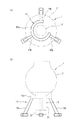
図16(a)は本発明の第9の実施形態に係る津波用シェルターを示す平面図であり、図16(b)はその津波用シェルターの側面図である。図16(a)及び(b)において、本実施形態の津波用シェルター1は、図14の第8の実施形態の津波用シェルター1の変形例を示すものであり、不使用時に球体2が転がり難い状態で球体2側を支持する架台19を備えている。この架台19は、突出体3を球体2の下方に垂下させた状態で球体2を支持するものであり、平面視においてC形に形成された支持部19aと、この支持部19aから地面に向かって延びる複数(本実施形態では3本)の脚部19bとを有している。   FIG. 16A is a plan view showing a tsunami shelter according to the ninth embodiment of the present invention, and FIG. 16B is a side view of the tsunami shelter. 16 (a) and 16 (b), the tsunami shelter 1 of this embodiment is a modification of the tsunami shelter 1 of the eighth embodiment of FIG. 14, and the sphere 2 rolls when not in use. A stand 19 that supports the sphere 2 side in a difficult state is provided. The gantry 19 supports the sphere 2 in a state where the projecting body 3 is suspended below the sphere 2, and has a support portion 19 a formed in a C shape in plan view and the support portion 19 a toward the ground. And a plurality of (three in this embodiment) leg portions 19b.

前記支持部19aは、その内径が突出体3の外径よりも大きく、かつ球体2の外径よりも小さく形成されており、支持部19a内に突出体3を挿通した状態で、球体2の下部に当接することにより、当該球体2を下方から支持するようになっている。前記脚部19bは、前記支持部19aの外周部に周方向等間隔に固定されており、その鉛直方向の高さは、突出体3の錘32が地面に接地しないように、突出体3の高さよりも長く形成されている。津波用シェルター1のその他の構成は、第8の実施形態と同様であるため、その説明を省略する。
なお、架台19は、地面に設置したジャッキ等により錘32を地面から離反させるようにしてもよい。また、本実施形態の架台19は、第1〜第7の実施形態の津波用シェルター1に適用することもができる。
The support portion 19a is formed so that its inner diameter is larger than the outer diameter of the projecting body 3 and smaller than the outer diameter of the sphere 2, and the projecting body 3 is inserted into the support section 19a. By contacting the lower part, the sphere 2 is supported from below. The leg portions 19b are fixed to the outer peripheral portion of the support portion 19a at equal intervals in the circumferential direction, and the height in the vertical direction is such that the weight 32 of the protrusion 3 does not contact the ground. It is longer than the height. Since the other structure of the tsunami shelter 1 is the same as that of the eighth embodiment, the description thereof is omitted.
The gantry 19 may be configured such that the weight 32 is separated from the ground by a jack or the like installed on the ground. Moreover, the mount frame 19 of this embodiment can also be applied to the tsunami shelter 1 of the first to seventh embodiments.

以上、本実施形態の津波用シェルター1によれば、不使用時に架台19によって球体2を安定した状態で支持することができる。また、津波用シェルター1の突出体3は地面上に接地することがないため、地面に溜まった雨水等により突出体3が腐食するのを抑制することができる。   As described above, according to the tsunami shelter 1 of the present embodiment, the sphere 2 can be stably supported by the gantry 19 when not in use. Moreover, since the protrusion 3 of the tsunami shelter 1 is not grounded on the ground, the protrusion 3 can be prevented from being corroded by rainwater or the like accumulated on the ground.

図17(a)は本発明の第10の実施形態に係る津波用シェルターを示す背面図であり、図17(b)はその側面図である。図17(a)及び(b)において、本実施形態の津波用シェルター1は、図16の第9の実施形態の津波用シェルター1の変形例を示すものであり、架台19の構成が異なる点で、第9の実施形態と相違する。本実施形態の架台19は、不使用時に津波用シェルター1を地面上に横倒しにした状態で突出体3側を支持するものであり、地面上に載置された架台本体19cと、この架台本体19cに突設された一対の規制部19dとによって構成されている。   FIG. 17A is a rear view showing a tsunami shelter according to the tenth embodiment of the present invention, and FIG. 17B is a side view thereof. 17 (a) and 17 (b), the tsunami shelter 1 of this embodiment is a modification of the tsunami shelter 1 of the ninth embodiment of FIG. 16, and the configuration of the gantry 19 is different. This is different from the ninth embodiment. The gantry 19 of the present embodiment supports the projecting body 3 in a state where the tsunami shelter 1 is laid down on the ground when not in use. The gantry main body 19c placed on the ground and the gantry main body It is comprised by a pair of control part 19d protrudingly provided by 19c.

架台本体19cは、例えば側面視において台形状に形成された矩形体からなり、その上面に突出本体部31の側周面が載置されている。架台本体19cの高さは、その上面に突出本体部31が載置された状態で、軸線Yが略水平となるように設定されている。各規制部19dは、架台本体19cの上面において図17(a)の左右両端部にそれぞれ突設されており、両規制部19dの間に突出本体部31が載置されている。これにより、突出本体部31が規制部19dに当接することにより、突出本体部31が架台本体19cの上面から図17(a)の左右両側に転がり落ちるのを規制することができる。その結果、球体2が地面上を転がるのを抑制することができる。
なお、本実施形態の架台19は、第1〜第7の実施形態の津波用シェルター1に適用することもができる。
The gantry body 19c is formed of, for example, a rectangular body formed in a trapezoidal shape in a side view, and the side peripheral surface of the projecting body portion 31 is placed on the upper surface thereof. The height of the gantry body 19c is set so that the axis Y is substantially horizontal in a state where the protruding body portion 31 is placed on the upper surface thereof. Each restricting portion 19d protrudes from the left and right ends of FIG. 17A on the upper surface of the gantry body 19c, and the projecting main body portion 31 is placed between the restricting portions 19d. As a result, the protruding main body 31 abuts against the restricting portion 19d, whereby the protruding main body 31 can be restricted from rolling down from the upper surface of the gantry main body 19c to the left and right sides of FIG. As a result, the sphere 2 can be prevented from rolling on the ground.
In addition, the mount frame 19 of this embodiment can also be applied to the tsunami shelter 1 of the first to seventh embodiments.

本実施形態の津波用シェルター1によれば、不使用時に球体2が転がり難い状態で突出体3を支持する架台19を備えているため、不使用時に架台19によって安定した状態で支持することができる。また、不使用時に津波用シェルター1は地面上に横倒しにされた状態であるため、球体2のハッチ蓋26を地面から低い位置で開閉することができる。したがって、球体2内への出入りを容易に行うことができる。   According to the tsunami shelter 1 of the present embodiment, since the sphere 2 is provided with the gantry 19 that supports the protruding body 3 in a state in which it is difficult to roll when not in use, it can be supported in a stable state by the gantry 19 when not in use. it can. Moreover, since the tsunami shelter 1 is lying on the ground when not in use, the hatch cover 26 of the sphere 2 can be opened and closed at a low position from the ground. Accordingly, it is possible to easily enter and exit the sphere 2.

なお、本発明は、上記の実施形態に限定されることなく適宜変更して実施可能である。例えば、上記実施形態の突出本体部31は、円筒状に形成されているが、角筒状に形成されていてもよい。また、浮力体4は、球体2が沈まない浮力を浮力するものであれば、その形状及び取付位置を任意に設定することができる。さらに、球体2や突出本体部31は、主殻板20,31a等により三分割するように形成されているが、二分割又は四分割以上するように形成されていてもよい。   The present invention is not limited to the above-described embodiment, and can be implemented with appropriate modifications. For example, the protruding main body portion 31 of the above embodiment is formed in a cylindrical shape, but may be formed in a rectangular tube shape. Moreover, if the buoyancy body 4 is buoyancy with the buoyancy which the sphere 2 does not sink, the shape and attachment position can be set arbitrarily. Furthermore, although the spherical body 2 and the protruding main body 31 are formed to be divided into three by the main shell plates 20, 31a, etc., they may be formed to be divided into two or more than four.

1 津波用シェルター
2 球体
2a 避難室
2c 脱出口
3 突出体
4 浮力体
4a 球体側浮力部
4c 分割浮力体
19 架台
22a 足載置部
31 突出本体部
31b 内部空間(バラスト室)
32 錘
32a 分割錘
W2 第2吃水線(吃水線)
DESCRIPTION OF SYMBOLS 1 Tsunami shelter 2 Sphere 2a Evacuation room 2c Exit 3 Projection 4 Buoyant body 4a Ball side buoyancy part 4c Split buoyancy body 19 Base 22a Foot placement part 31 Projection main part 31b Internal space (ballast room)
32 weight 32a divided weight W2 2nd waterline (waterline)

Claims (13)

津波到来時にその流れに乗って自由漂流する津波用シェルターであって、
内部に避難室を有する中空状の球体と、
前記自由漂流している状態で前記球体の下方に突出するとともに、その突出端側に錘を有する突出体と、
前記自由漂流時に前記球体内が浸水した状態で、前記球体が沈まない浮力を付与する浮力体と、
を備え
前記突出体は、有底筒状に形成された突出本体部を有し、
前記浮力体の一部が、前記突出本体部内に収容されていることを特徴とする津波用シェルター。
A tsunami shelter that drifts freely on the flow of the tsunami,
A hollow sphere having an evacuation chamber inside;
Projecting below the sphere in the state of free drifting, and a projecting body having a weight on the projecting end side thereof,
A buoyancy body that imparts a buoyancy in which the sphere does not sink in a state where the sphere has been submerged during the free drift; and
Equipped with a,
The projecting body has a projecting main body formed in a bottomed cylindrical shape,
A tsunami shelter characterized in that a part of the buoyancy body is accommodated in the protruding main body .
前記球体には、前記浸水した状態で当該球体の吃水線よりも上方の位置に、外部に脱出可能な脱出口が形成されている請求項1に記載の津波用シェルター。   2. The tsunami shelter according to claim 1, wherein the sphere is formed with an exit port that can escape to the outside at a position above the inundation line of the sphere in the flooded state. 前記球体の外周には、前記浸水した状態で当該球体の吃水線よりも上方の位置に、足載置部が設けられている請求項2に記載の津波用シェルター。   The tsunami shelter according to claim 2, wherein a footrest is provided on the outer periphery of the sphere at a position above the waterline of the sphere in the flooded state. 地面上に横倒しにされた状態で、前記球体側と前記突出体側とが接地した二点接地状態となる請求項1〜3のいずれか一項に記載の津波用シェルター。   The tsunami shelter according to any one of claims 1 to 3, wherein the tsunami shelter is in a two-point grounding state in which the sphere side and the projecting body side are grounded while being laid down on the ground. 前記錘は、津波到来時にその流れによって前記突出体が地面上を引きずられながら離陸する程度の重さに設定されている請求項1〜4のいずれか一項に記載の津波用シェルター。   The tsunami shelter according to any one of claims 1 to 4, wherein the weight is set to a weight that allows the projecting body to take off while being dragged on the ground when the tsunami arrives. 前記浮力体は、前記自由漂流している状態で前記球体の赤道よりも径方向外方に突出して形成された球体側浮力部を有している請求項1〜5のいずれか一項に記載の津波用シェルター。   The said buoyancy body has the spherical body side buoyancy part formed so that it might protrude in the radial direction outward rather than the equator of the said spherical body in the said free drifting state. Tsunami shelter. 前記浮力体は、前記球体の内部に配置された球体側浮力部を有している請求項1〜5のいずれか一項に記載の津波用シェルター。   The said buoyancy body is a tsunami shelter as described in any one of Claims 1-5 which has the spherical body side buoyancy part arrange | positioned inside the said spherical body. 前記浮力体は、複数に分割された分割浮力体を有し、
前記各分割浮力体が、前記球体に対して着脱可能に取り付けられている請求項1〜7のいずれか一項に記載の津波用シェルター。
The buoyancy body has a divided buoyancy body divided into a plurality of parts,
The tsunami shelter according to any one of claims 1 to 7, wherein each of the divided buoyancy bodies is detachably attached to the sphere.
記錘前記突出本体部に対して着脱可能に取り付けられている請求項1〜8のいずれか一項に記載の津波用シェルター。 Tsunami for shelter according to any one of Motomeko 1-8 that have been detachably attached to the front Kitsumu said projecting body portion. 前記錘は、複数に分割された分割錘からなり、
前記各分割錘が、前記突出本体部に対して着脱可能に取り付けられている請求項に記載の津波用シェルター。
The weight comprises a divided weight divided into a plurality of weights,
The tsunami shelter according to claim 9 , wherein each of the divided weights is detachably attached to the projecting main body.
前記突出本体部は、前記球体に対して着脱可能に取り付けられている請求項1〜10のいずれか一項に記載の津波用シェルター。 The said protrusion main-body part is a tsunami shelter as described in any one of Claims 1-10 attached to the said spherical body so that attachment or detachment is possible. 前記突出本体部が、前記球体の材質よりも比重の大きい材質で形成されている請求項1〜11のいずれか一項に記載の津波用シェルター。 The tsunami shelter according to any one of claims 1 to 11 , wherein the protruding main body is formed of a material having a specific gravity greater than that of the sphere. 不使用時に前記球体が転がり難い状態で当該球体側又は前記突出体側を支持する架台を備えている請求項1〜12のいずれか一項に記載の津波用シェルター The tsunami shelter according to any one of claims 1 to 12 , further comprising a gantry that supports the sphere side or the protruding body side in a state in which the sphere hardly rolls when not in use .
JP2012219567A 2012-10-01 2012-10-01 Tsunami shelter Active JP5986867B2 (en)

Priority Applications (1)

Application Number Priority Date Filing Date Title
JP2012219567A JP5986867B2 (en) 2012-10-01 2012-10-01 Tsunami shelter

Applications Claiming Priority (1)

Application Number Priority Date Filing Date Title
JP2012219567A JP5986867B2 (en) 2012-10-01 2012-10-01 Tsunami shelter

Publications (2)

Publication Number Publication Date
JP2014069778A JP2014069778A (en) 2014-04-21
JP5986867B2 true JP5986867B2 (en) 2016-09-06

Family

ID=50745369

Family Applications (1)

Application Number Title Priority Date Filing Date
JP2012219567A Active JP5986867B2 (en) 2012-10-01 2012-10-01 Tsunami shelter

Country Status (1)

Country Link
JP (1) JP5986867B2 (en)

Families Citing this family (2)

* Cited by examiner, † Cited by third party
Publication number Priority date Publication date Assignee Title
JP5893103B1 (en) * 2014-08-27 2016-03-23 株式会社高知丸高 Boat-type shelter and camper
CN116588245B (en) * 2023-07-17 2023-10-17 青岛金晶股份有限公司 Ship porthole

Family Cites Families (8)

* Cited by examiner, † Cited by third party
Publication number Priority date Publication date Assignee Title
JPS5140234Y2 (en) * 1972-11-18 1976-10-01
JPS5070696U (en) * 1973-10-25 1975-06-23
JP3541197B1 (en) * 2003-04-28 2004-07-07 文嗣 松葉 Floating shelter installed on the ground for disaster prevention against tsunami or flood
JP3113372U (en) * 2005-05-17 2005-09-08 明徳産業株式会社 Floating body
JP4302668B2 (en) * 2005-06-29 2009-07-29 株式会社ゼニライトブイ High wave buoy
JP4084408B2 (en) * 2006-07-05 2008-04-30 政行 田口 Tsunami shelter device
JP2009208591A (en) * 2008-03-04 2009-09-17 Shinko Chemical Inc Amphibious house
JP2012206640A (en) * 2011-03-30 2012-10-25 Takeshi Nakagawa Life-saving capsule against tsunami and flood

Also Published As

Publication number Publication date
JP2014069778A (en) 2014-04-21

Similar Documents

Publication Publication Date Title
KR101773596B1 (en) Ship with system for preventing sinking and capsizal in case of emergency
JP3541197B1 (en) Floating shelter installed on the ground for disaster prevention against tsunami or flood
US3883913A (en) Aquastabilized survival raft
US8047886B1 (en) Round tube boat
US20110240692A1 (en) Survival backpack that converts to a personal flotation device
WO2008011783A1 (en) Overturn-proof waterborne life-saving device
EP2476400B1 (en) Stretcher usable as a life raft
JP2007331660A (en) Rescuing capsule
WO2014125503A2 (en) Rounded life boat
JP2012206640A (en) Life-saving capsule against tsunami and flood
JP5986867B2 (en) Tsunami shelter
US9150292B2 (en) Inflatable floatable unit
WO2014076351A1 (en) Arrangement and method for underwater activities
JP5568590B2 (en) Tsunami shelter
US3060465A (en) Life globe
US20110197881A1 (en) Underwater Breathing Apparatus
CN103608257B (en) Inflatable appliance for lifesaving appliance
US3222700A (en) Inflatable liferafts
US2888690A (en) Inflatable life-saving raft
WO2014148882A1 (en) A floatation apparatus
CN205113642U (en) Whole boats and ships lifesaving gasbag deposit storehouse
US20220266959A1 (en) Personal watercraft and systems and apparatuses for use therewith
JP3166415U (en) Composite boat
CN107776843A (en) Intelligence adjusts system of inclining
JP2021166614A (en) Bed for flood control measures

Legal Events

Date Code Title Description
A621 Written request for application examination

Free format text: JAPANESE INTERMEDIATE CODE: A621

Effective date: 20150708

A977 Report on retrieval

Free format text: JAPANESE INTERMEDIATE CODE: A971007

Effective date: 20160426

A131 Notification of reasons for refusal

Free format text: JAPANESE INTERMEDIATE CODE: A131

Effective date: 20160510

A521 Request for written amendment filed

Free format text: JAPANESE INTERMEDIATE CODE: A523

Effective date: 20160518

TRDD Decision of grant or rejection written
A01 Written decision to grant a patent or to grant a registration (utility model)

Free format text: JAPANESE INTERMEDIATE CODE: A01

Effective date: 20160802

A61 First payment of annual fees (during grant procedure)

Free format text: JAPANESE INTERMEDIATE CODE: A61

Effective date: 20160808

R150 Certificate of patent or registration of utility model

Ref document number: 5986867

Country of ref document: JP

Free format text: JAPANESE INTERMEDIATE CODE: R150

R250 Receipt of annual fees

Free format text: JAPANESE INTERMEDIATE CODE: R250

R250 Receipt of annual fees

Free format text: JAPANESE INTERMEDIATE CODE: R250

R250 Receipt of annual fees

Free format text: JAPANESE INTERMEDIATE CODE: R250

R250 Receipt of annual fees

Free format text: JAPANESE INTERMEDIATE CODE: R250

R250 Receipt of annual fees

Free format text: JAPANESE INTERMEDIATE CODE: R250