JP5986736B2 - Exhaust gas purification system for internal combustion engine - Google Patents
Exhaust gas purification system for internal combustion engine Download PDFInfo
- Publication number
- JP5986736B2 JP5986736B2 JP2011251048A JP2011251048A JP5986736B2 JP 5986736 B2 JP5986736 B2 JP 5986736B2 JP 2011251048 A JP2011251048 A JP 2011251048A JP 2011251048 A JP2011251048 A JP 2011251048A JP 5986736 B2 JP5986736 B2 JP 5986736B2
- Authority
- JP
- Japan
- Prior art keywords
- engine
- air flow
- temperature
- flow rate
- control means
- Prior art date
- Legal status (The legal status is an assumption and is not a legal conclusion. Google has not performed a legal analysis and makes no representation as to the accuracy of the status listed.)
- Active
Links
Images


Classifications
-
- F—MECHANICAL ENGINEERING; LIGHTING; HEATING; WEAPONS; BLASTING
- F02—COMBUSTION ENGINES; HOT-GAS OR COMBUSTION-PRODUCT ENGINE PLANTS
- F02D—CONTROLLING COMBUSTION ENGINES
- F02D13/00—Controlling the engine output power by varying inlet or exhaust valve operating characteristics, e.g. timing
- F02D13/02—Controlling the engine output power by varying inlet or exhaust valve operating characteristics, e.g. timing during engine operation
-
- F—MECHANICAL ENGINEERING; LIGHTING; HEATING; WEAPONS; BLASTING
- F01—MACHINES OR ENGINES IN GENERAL; ENGINE PLANTS IN GENERAL; STEAM ENGINES
- F01N—GAS-FLOW SILENCERS OR EXHAUST APPARATUS FOR MACHINES OR ENGINES IN GENERAL; GAS-FLOW SILENCERS OR EXHAUST APPARATUS FOR INTERNAL COMBUSTION ENGINES
- F01N3/00—Exhaust or silencing apparatus having means for purifying, rendering innocuous, or otherwise treating exhaust
- F01N3/02—Exhaust or silencing apparatus having means for purifying, rendering innocuous, or otherwise treating exhaust for cooling, or for removing solid constituents of, exhaust
- F01N3/021—Exhaust or silencing apparatus having means for purifying, rendering innocuous, or otherwise treating exhaust for cooling, or for removing solid constituents of, exhaust by means of filters
- F01N3/023—Exhaust or silencing apparatus having means for purifying, rendering innocuous, or otherwise treating exhaust for cooling, or for removing solid constituents of, exhaust by means of filters using means for regenerating the filters, e.g. by burning trapped particles
-
- F—MECHANICAL ENGINEERING; LIGHTING; HEATING; WEAPONS; BLASTING
- F01—MACHINES OR ENGINES IN GENERAL; ENGINE PLANTS IN GENERAL; STEAM ENGINES
- F01N—GAS-FLOW SILENCERS OR EXHAUST APPARATUS FOR MACHINES OR ENGINES IN GENERAL; GAS-FLOW SILENCERS OR EXHAUST APPARATUS FOR INTERNAL COMBUSTION ENGINES
- F01N3/00—Exhaust or silencing apparatus having means for purifying, rendering innocuous, or otherwise treating exhaust
- F01N3/08—Exhaust or silencing apparatus having means for purifying, rendering innocuous, or otherwise treating exhaust for rendering innocuous
- F01N3/10—Exhaust or silencing apparatus having means for purifying, rendering innocuous, or otherwise treating exhaust for rendering innocuous by thermal or catalytic conversion of noxious components of exhaust
- F01N3/105—General auxiliary catalysts, e.g. upstream or downstream of the main catalyst
- F01N3/106—Auxiliary oxidation catalysts
-
- F—MECHANICAL ENGINEERING; LIGHTING; HEATING; WEAPONS; BLASTING
- F01—MACHINES OR ENGINES IN GENERAL; ENGINE PLANTS IN GENERAL; STEAM ENGINES
- F01N—GAS-FLOW SILENCERS OR EXHAUST APPARATUS FOR MACHINES OR ENGINES IN GENERAL; GAS-FLOW SILENCERS OR EXHAUST APPARATUS FOR INTERNAL COMBUSTION ENGINES
- F01N3/00—Exhaust or silencing apparatus having means for purifying, rendering innocuous, or otherwise treating exhaust
- F01N3/08—Exhaust or silencing apparatus having means for purifying, rendering innocuous, or otherwise treating exhaust for rendering innocuous
- F01N3/10—Exhaust or silencing apparatus having means for purifying, rendering innocuous, or otherwise treating exhaust for rendering innocuous by thermal or catalytic conversion of noxious components of exhaust
- F01N3/18—Exhaust or silencing apparatus having means for purifying, rendering innocuous, or otherwise treating exhaust for rendering innocuous by thermal or catalytic conversion of noxious components of exhaust characterised by methods of operation; Control
- F01N3/20—Exhaust or silencing apparatus having means for purifying, rendering innocuous, or otherwise treating exhaust for rendering innocuous by thermal or catalytic conversion of noxious components of exhaust characterised by methods of operation; Control specially adapted for catalytic conversion ; Methods of operation or control of catalytic converters
- F01N3/2066—Selective catalytic reduction [SCR]
-
- F—MECHANICAL ENGINEERING; LIGHTING; HEATING; WEAPONS; BLASTING
- F02—COMBUSTION ENGINES; HOT-GAS OR COMBUSTION-PRODUCT ENGINE PLANTS
- F02D—CONTROLLING COMBUSTION ENGINES
- F02D35/00—Controlling engines, dependent on conditions exterior or interior to engines, not otherwise provided for
- F02D35/02—Controlling engines, dependent on conditions exterior or interior to engines, not otherwise provided for on interior conditions
- F02D35/023—Controlling engines, dependent on conditions exterior or interior to engines, not otherwise provided for on interior conditions by determining the cylinder pressure
-
- F—MECHANICAL ENGINEERING; LIGHTING; HEATING; WEAPONS; BLASTING
- F02—COMBUSTION ENGINES; HOT-GAS OR COMBUSTION-PRODUCT ENGINE PLANTS
- F02D—CONTROLLING COMBUSTION ENGINES
- F02D41/00—Electrical control of supply of combustible mixture or its constituents
- F02D41/0002—Controlling intake air
-
- F—MECHANICAL ENGINEERING; LIGHTING; HEATING; WEAPONS; BLASTING
- F02—COMBUSTION ENGINES; HOT-GAS OR COMBUSTION-PRODUCT ENGINE PLANTS
- F02D—CONTROLLING COMBUSTION ENGINES
- F02D41/00—Electrical control of supply of combustible mixture or its constituents
- F02D41/02—Circuit arrangements for generating control signals
- F02D41/021—Introducing corrections for particular conditions exterior to the engine
- F02D41/0235—Introducing corrections for particular conditions exterior to the engine in relation with the state of the exhaust gas treating apparatus
- F02D41/024—Introducing corrections for particular conditions exterior to the engine in relation with the state of the exhaust gas treating apparatus to increase temperature of the exhaust gas treating apparatus
- F02D41/0255—Introducing corrections for particular conditions exterior to the engine in relation with the state of the exhaust gas treating apparatus to increase temperature of the exhaust gas treating apparatus to accelerate the warming-up of the exhaust gas treating apparatus at engine start
-
- F—MECHANICAL ENGINEERING; LIGHTING; HEATING; WEAPONS; BLASTING
- F02—COMBUSTION ENGINES; HOT-GAS OR COMBUSTION-PRODUCT ENGINE PLANTS
- F02D—CONTROLLING COMBUSTION ENGINES
- F02D41/00—Electrical control of supply of combustible mixture or its constituents
- F02D41/30—Controlling fuel injection
- F02D41/38—Controlling fuel injection of the high pressure type
- F02D41/40—Controlling fuel injection of the high pressure type with means for controlling injection timing or duration
- F02D41/401—Controlling injection timing
-
- F—MECHANICAL ENGINEERING; LIGHTING; HEATING; WEAPONS; BLASTING
- F02—COMBUSTION ENGINES; HOT-GAS OR COMBUSTION-PRODUCT ENGINE PLANTS
- F02D—CONTROLLING COMBUSTION ENGINES
- F02D2200/00—Input parameters for engine control
- F02D2200/02—Input parameters for engine control the parameters being related to the engine
- F02D2200/021—Engine temperature
-
- F—MECHANICAL ENGINEERING; LIGHTING; HEATING; WEAPONS; BLASTING
- F02—COMBUSTION ENGINES; HOT-GAS OR COMBUSTION-PRODUCT ENGINE PLANTS
- F02D—CONTROLLING COMBUSTION ENGINES
- F02D2200/00—Input parameters for engine control
- F02D2200/02—Input parameters for engine control the parameters being related to the engine
- F02D2200/04—Engine intake system parameters
- F02D2200/0414—Air temperature
-
- F—MECHANICAL ENGINEERING; LIGHTING; HEATING; WEAPONS; BLASTING
- F02—COMBUSTION ENGINES; HOT-GAS OR COMBUSTION-PRODUCT ENGINE PLANTS
- F02D—CONTROLLING COMBUSTION ENGINES
- F02D2200/00—Input parameters for engine control
- F02D2200/70—Input parameters for engine control said parameters being related to the vehicle exterior
- F02D2200/703—Atmospheric pressure
-
- F—MECHANICAL ENGINEERING; LIGHTING; HEATING; WEAPONS; BLASTING
- F02—COMBUSTION ENGINES; HOT-GAS OR COMBUSTION-PRODUCT ENGINE PLANTS
- F02D—CONTROLLING COMBUSTION ENGINES
- F02D35/00—Controlling engines, dependent on conditions exterior or interior to engines, not otherwise provided for
- F02D35/02—Controlling engines, dependent on conditions exterior or interior to engines, not otherwise provided for on interior conditions
- F02D35/023—Controlling engines, dependent on conditions exterior or interior to engines, not otherwise provided for on interior conditions by determining the cylinder pressure
- F02D35/024—Controlling engines, dependent on conditions exterior or interior to engines, not otherwise provided for on interior conditions by determining the cylinder pressure using an estimation
-
- F—MECHANICAL ENGINEERING; LIGHTING; HEATING; WEAPONS; BLASTING
- F02—COMBUSTION ENGINES; HOT-GAS OR COMBUSTION-PRODUCT ENGINE PLANTS
- F02D—CONTROLLING COMBUSTION ENGINES
- F02D35/00—Controlling engines, dependent on conditions exterior or interior to engines, not otherwise provided for
- F02D35/02—Controlling engines, dependent on conditions exterior or interior to engines, not otherwise provided for on interior conditions
- F02D35/025—Controlling engines, dependent on conditions exterior or interior to engines, not otherwise provided for on interior conditions by determining temperatures inside the cylinder, e.g. combustion temperatures
- F02D35/026—Controlling engines, dependent on conditions exterior or interior to engines, not otherwise provided for on interior conditions by determining temperatures inside the cylinder, e.g. combustion temperatures using an estimation
-
- F—MECHANICAL ENGINEERING; LIGHTING; HEATING; WEAPONS; BLASTING
- F02—COMBUSTION ENGINES; HOT-GAS OR COMBUSTION-PRODUCT ENGINE PLANTS
- F02D—CONTROLLING COMBUSTION ENGINES
- F02D41/00—Electrical control of supply of combustible mixture or its constituents
- F02D41/0002—Controlling intake air
- F02D41/0007—Controlling intake air for control of turbo-charged or super-charged engines
-
- Y—GENERAL TAGGING OF NEW TECHNOLOGICAL DEVELOPMENTS; GENERAL TAGGING OF CROSS-SECTIONAL TECHNOLOGIES SPANNING OVER SEVERAL SECTIONS OF THE IPC; TECHNICAL SUBJECTS COVERED BY FORMER USPC CROSS-REFERENCE ART COLLECTIONS [XRACs] AND DIGESTS
- Y02—TECHNOLOGIES OR APPLICATIONS FOR MITIGATION OR ADAPTATION AGAINST CLIMATE CHANGE
- Y02A—TECHNOLOGIES FOR ADAPTATION TO CLIMATE CHANGE
- Y02A50/00—TECHNOLOGIES FOR ADAPTATION TO CLIMATE CHANGE in human health protection, e.g. against extreme weather
- Y02A50/20—Air quality improvement or preservation, e.g. vehicle emission control or emission reduction by using catalytic converters
-
- Y—GENERAL TAGGING OF NEW TECHNOLOGICAL DEVELOPMENTS; GENERAL TAGGING OF CROSS-SECTIONAL TECHNOLOGIES SPANNING OVER SEVERAL SECTIONS OF THE IPC; TECHNICAL SUBJECTS COVERED BY FORMER USPC CROSS-REFERENCE ART COLLECTIONS [XRACs] AND DIGESTS
- Y02—TECHNOLOGIES OR APPLICATIONS FOR MITIGATION OR ADAPTATION AGAINST CLIMATE CHANGE
- Y02T—CLIMATE CHANGE MITIGATION TECHNOLOGIES RELATED TO TRANSPORTATION
- Y02T10/00—Road transport of goods or passengers
- Y02T10/10—Internal combustion engine [ICE] based vehicles
- Y02T10/12—Improving ICE efficiencies
-
- Y—GENERAL TAGGING OF NEW TECHNOLOGICAL DEVELOPMENTS; GENERAL TAGGING OF CROSS-SECTIONAL TECHNOLOGIES SPANNING OVER SEVERAL SECTIONS OF THE IPC; TECHNICAL SUBJECTS COVERED BY FORMER USPC CROSS-REFERENCE ART COLLECTIONS [XRACs] AND DIGESTS
- Y02—TECHNOLOGIES OR APPLICATIONS FOR MITIGATION OR ADAPTATION AGAINST CLIMATE CHANGE
- Y02T—CLIMATE CHANGE MITIGATION TECHNOLOGIES RELATED TO TRANSPORTATION
- Y02T10/00—Road transport of goods or passengers
- Y02T10/10—Internal combustion engine [ICE] based vehicles
- Y02T10/40—Engine management systems
Landscapes
- Engineering & Computer Science (AREA)
- Chemical & Material Sciences (AREA)
- Combustion & Propulsion (AREA)
- Mechanical Engineering (AREA)
- General Engineering & Computer Science (AREA)
- Chemical Kinetics & Catalysis (AREA)
- Health & Medical Sciences (AREA)
- Materials Engineering (AREA)
- Toxicology (AREA)
- Combined Controls Of Internal Combustion Engines (AREA)
- Exhaust Gas After Treatment (AREA)
- Electrical Control Of Air Or Fuel Supplied To Internal-Combustion Engine (AREA)
- Control Of Throttle Valves Provided In The Intake System Or In The Exhaust System (AREA)
- Exhaust-Gas Circulating Devices (AREA)
Description
本発明は、DOC、DPF、SCRなどの排気浄化装置を備えた内燃機関の排気浄化システムに関し、詳しくは、エンジン始動直後などの暖機運転時において、早期に排気浄化装置を昇温させるための技術に関する。 The present invention relates to an exhaust gas purification system for an internal combustion engine equipped with exhaust gas purification devices such as DOC, DPF, and SCR. More specifically, the present invention relates to a method for quickly raising the temperature of an exhaust gas purification device during warm-up operation such as immediately after engine startup. Regarding technology.
酸化触媒(DOC)、ディーゼルパティキュレートフィルタ(DPF)、選択的還元触媒(SCR)などの排気浄化装置は、所定以上の温度環境にならないと浄化機能が十分に発揮されない。例えば、図18は、窒素酸化物(NOX)を還元して浄化するSCR装置において、SCR触媒担体温度、SCR入出口におけるNOX濃度、およびエンジン運転時間との関係を示した図である。この図18からも分かるように、SCR装置の触媒担体温度が活性温度に達するまでの間は、SCR出口のNOX濃度が相対的に高くなっており、SCR装置によるNOX浄化機能が十分に発揮されていないことが分かる。よって、エンジン始動直後などの暖機運転時において、早期に排気浄化が行われるようにするためには、SCR装置などの排気浄化装置を早期に昇温する必要がある。 Exhaust purification devices such as an oxidation catalyst (DOC), a diesel particulate filter (DPF), and a selective reduction catalyst (SCR) do not sufficiently perform the purification function unless the temperature environment exceeds a predetermined level. For example, FIG. 18 is a graph showing the relationship between the SCR catalyst carrier temperature, the NO X concentration at the SCR inlet / outlet, and the engine operating time in an SCR device that reduces and purifies nitrogen oxides (NO X ). As can be seen from FIG. 18, until the catalyst carrier temperature of the SCR device reaches the activation temperature, NO X concentration SCR outlet has relatively high, is sufficiently NO X purifying function by SCR device It turns out that it is not demonstrated. Therefore, in order to perform exhaust purification at an early stage during warm-up operation such as immediately after engine startup, it is necessary to raise the temperature of an exhaust purification apparatus such as an SCR device at an early stage.
従来、排気浄化装置を早期に昇温するために、燃料を噴射するタイミングを変更することや、可変過給機や吸気スロットルを制御してエンジンに供給される空気流量を制御(低減)することが行われている。例えば、特許文献1には、燃料を噴射するタイミングを変更する噴射タイミング制御の一例が開示されている。また特許文献2には、エンジンに供給される空気流量を制御(低減)する空気流量制御の一例が開示されている。
Conventionally, in order to raise the temperature of the exhaust purification device early, the timing of fuel injection is changed, and the flow rate of air supplied to the engine is controlled (reduced) by controlling the variable turbocharger and the intake throttle. Has been done. For example,
上述した排気浄化装置の早期昇温技術の中で、空気流量制御は昇温効果が比較的大きいものである。しかしながら、エンジンに供給する空気流量を制御(低減)すると、気筒内の圧力が低下するため、暖機運転時の早い時期に空気流量制御を実施すると、エンジンの燃焼が不安定となる場合がある。 Among the above-mentioned early temperature raising technologies for the exhaust gas purification apparatus, the air flow rate control has a relatively large temperature raising effect. However, if the flow rate of air supplied to the engine is controlled (reduced), the pressure in the cylinder will drop, so if the air flow rate control is performed early in the warm-up operation, combustion of the engine may become unstable. .
図19は、従来技術において、空気流量制御を開始するタイミングと、エンジン燃焼状態との関係を説明するための図である。エンジン燃焼状態の安定/不安定は、燃料の噴射タイミングにおける気筒内温度(Tcyl)と気筒内圧力(Pcyl)によって評価することができ、気筒内の温度および圧力が高いほど、エンジンの燃焼状態が安定していると評価することができる。そして図19に示すように、エンジン始動直後のまだエンジンの燃焼状態が不安定な状態において、すぐに空気流量制御(ii)を実施すると、エンジンの燃焼状態がより不安定になってしまう。また、空気流量制御(ii)に先立って噴射タイミング制御(i)を実施して気筒内を昇温した場合でも、気筒内の昇温が不十分だと、空気流量制御(ii´)によって気筒内の圧力が低下し、エンジンの燃焼状態が不安定になってしまう。 FIG. 19 is a diagram for explaining the relationship between the timing of starting air flow control and the engine combustion state in the prior art. The stability / instability of the engine combustion state can be evaluated by the cylinder temperature (T cyl ) and the cylinder pressure (P cyl ) at the fuel injection timing. The higher the cylinder temperature and pressure, the more the engine combustion It can be evaluated that the state is stable. As shown in FIG. 19, if the air flow rate control (ii) is performed immediately in a state where the combustion state of the engine is still unstable immediately after starting the engine, the combustion state of the engine becomes more unstable. Even when the injection timing control (i) is performed prior to the air flow rate control (ii) to raise the temperature in the cylinder, if the temperature rise in the cylinder is insufficient, the air flow rate control (ii ′) The internal pressure drops, and the combustion state of the engine becomes unstable.
エンジンの燃焼状態が不安定になると、炭化水素(HC)排出量が増加するとともに、最悪の場合には、失火に至ってエンジンが停止してしまう。排気ガスに対する規制が年々厳しくなる中、エンジン始動直後などの暖機運転時において、エンジンの安定燃焼を確保しつつ、早期に排気浄化装置の昇温を図ることのできる排気浄化システムの開発が強く望まれている。 When the combustion state of the engine becomes unstable, hydrocarbon (HC) emission increases, and in the worst case, misfire occurs and the engine stops. As exhaust gas regulations become stricter year by year, the development of an exhaust purification system that can quickly raise the temperature of the exhaust purification device while ensuring stable combustion of the engine during warm-up operations such as immediately after starting the engine is strong. It is desired.
本発明はこのような従来技術の課題に鑑みなされた発明であって、エンジン始動直後などの暖機運転時において、エンジンの安定燃焼を確保しつつ、HC排出量の増加を抑制し、早期に排気浄化装置の昇温を図ることができる内燃機関の排気浄化システムを提供することを目的としている。 The present invention has been made in view of the problems of the prior art, and at the time of warm-up operation such as immediately after engine start-up, while ensuring stable combustion of the engine, it suppresses an increase in HC emissions, and promptly An object of the present invention is to provide an exhaust gas purification system for an internal combustion engine capable of increasing the temperature of the exhaust gas purification device.
本発明は、上述したような従来技術における課題及び目的を達成するために発明されたものであって、
本発明の内燃機関の排気浄化システムは、
エンジンと、該エンジンから排出される排気ガスが通過する排気通路と、該排気通路に設置された排気浄化装置とを備えた内燃機関の排気浄化システムにおいて、
前記エンジンに供給される空気流量を低減することで前記エンジンから排出される排気ガスの昇温を図る空気流量制御手段と、該空気流量制御手段が作動するタイミングを制御する作動タイミング制御手段とを有し、
前記作動タイミング制御手段は、前記空気流量制御手段が作動して前記エンジンに供給される空気流量が低減されても、前記エンジンの燃焼状態が不安定とならないように、前記空気流量制御手段が作動するタイミングを制御するように構成されていることを特徴とする。
The present invention has been invented in order to achieve the problems and objects in the prior art as described above,
An exhaust gas purification system for an internal combustion engine of the present invention includes:
In an exhaust purification system of an internal combustion engine comprising an engine, an exhaust passage through which exhaust gas discharged from the engine passes, and an exhaust purification device installed in the exhaust passage,
An air flow rate control means for increasing the temperature of exhaust gas discharged from the engine by reducing an air flow rate supplied to the engine; and an operation timing control means for controlling the timing at which the air flow rate control means is activated. Have
The operation timing control means operates so that the combustion state of the engine does not become unstable even if the air flow control means is operated to reduce the air flow supplied to the engine. It is configured to control the timing to perform.
このように本発明では、空気流量制御手段が作動してエンジンに供給される空気流量が低減されても、エンジンの燃焼状態が不安定とならないように、空気流量制御手段が作動するタイミングを作動タイミング制御手段によって制御している。空気流量制御は昇温効果が大きいものの、エンジンの燃焼を不安定にする恐れがあるとの欠点があったが、本発明によれば、エンジンの安定燃焼を確保しつつ、HC排出量の増加を抑制し、早期に排気浄化装置の昇温を図ることができる内燃機関の排気浄化システムとすることができる。 As described above, in the present invention, even when the air flow rate control unit is activated and the air flow rate supplied to the engine is reduced, the timing at which the air flow rate control unit is activated is activated so that the combustion state of the engine does not become unstable. It is controlled by timing control means. Although the air flow rate control has a large temperature rise effect, there is a drawback that the combustion of the engine may become unstable. However, according to the present invention, the HC emission amount is increased while ensuring the stable combustion of the engine. Thus, an exhaust gas purification system for an internal combustion engine can be provided in which the temperature of the exhaust gas purification device can be increased quickly.
上記発明において、
前記作動タイミング制御手段は、エンジンの始動から所定時間が経過した後に、前記空気流量制御手段を作動させるように構成されており、当該所定時間は、前記エンジンのエンジン回転数および燃料噴射量と対応して算出される。この際、前記所定時間は、前記エンジンが作動している状態における外気温および大気圧の少なくともいずれか一つに対応して補正されることが望ましい。
In the above invention,
The operation timing control means is configured to operate the air flow rate control means after a predetermined time has elapsed from the start of the engine, and the predetermined time corresponds to the engine speed and the fuel injection amount of the engine. Is calculated. At this time, it is preferable that the predetermined time is corrected corresponding to at least one of an outside air temperature and an atmospheric pressure when the engine is operating.
このような本発明によれば、エンジン始動直後における排気浄化装置の昇温と、HC排出量の増加抑制とを、簡易的な方法で制御することができる。またこの際、外気温および/または大気圧に応じて、空気流量制御手段が作動するまでの所定時間を補正することで、外気温や大気圧に応じて精度よく空気流量制御手段を作動させるタイミングを決定することができる。 According to the present invention as described above, it is possible to control the temperature rise of the exhaust gas purification apparatus immediately after engine startup and the suppression of the increase in the HC emission amount by a simple method. Further, at this time, by correcting the predetermined time until the air flow control means is activated according to the outside air temperature and / or the atmospheric pressure, the timing at which the air flow control means is accurately operated according to the outside air temperature and the atmospheric pressure. Can be determined.
また上記発明において、
前記作動タイミング制御手段は、前記エンジンを冷却するエンジン冷却水もしくは前記エンジン内部を通過する潤滑油の温度が閾値以上になった場合に、前記空気流量制御手段を作動させるように構成することができる。この際、前記冷却水温度もしくは潤滑油温度の閾値は、前記エンジンが作動している状態における外気温および大気圧の少なくともいずれか一つに対応して補正されることが望ましい。
In the above invention,
The operation timing control means can be configured to operate the air flow rate control means when the temperature of engine coolant for cooling the engine or the lubricating oil passing through the engine exceeds a threshold value. . At this time, it is preferable that the threshold value of the cooling water temperature or the lubricating oil temperature is corrected corresponding to at least one of an outside air temperature and an atmospheric pressure when the engine is operating.
このような本発明によれば、エンジン冷却水もしくは潤滑油の温度からエンジンの燃焼状態を把握することで、空気流量制御手段が作動するタイミングを制御することができる。よって、エンジンの安定燃焼を確保しつつ、早期に排気浄化装置の昇温を図ることができる。またこの際、外気温および/または大気圧に応じて冷却水温度もしくは潤滑油温度の閾値を補正することで、外気温や大気圧に応じて精度よく空気流量制御手段を作動させるタイミングを決定することができる。 According to the present invention as described above, the timing at which the air flow rate control means operates can be controlled by grasping the combustion state of the engine from the temperature of the engine coolant or the lubricating oil. Therefore, it is possible to quickly raise the temperature of the exhaust gas purification device while ensuring stable combustion of the engine. Further, at this time, the timing for operating the air flow rate control means with high accuracy according to the outside air temperature or the atmospheric pressure is determined by correcting the threshold value of the cooling water temperature or the lubricating oil temperature according to the outside air temperature and / or the atmospheric pressure. be able to.
また上記発明において、
前記作動タイミング制御手段は、前記エンジンの気筒内の温度および圧力を推定し、該推定された気筒内の温度および圧力に基づいて、前記空気流量制御手段が作動するタイミングを制御するように構成することができる。
In the above invention,
The operation timing control means is configured to estimate a temperature and pressure in a cylinder of the engine, and to control a timing at which the air flow control means is operated based on the estimated temperature and pressure in the cylinder. be able to.
このような本発明によれば、空気流量制御を実施した後のエンジンの燃焼状態を精度よく推定した上で、空気流量制御手段が作動するタイミングを制御するため、エンジンの安定燃焼を確保しつつ、早期に排気浄化装置の昇温を図ることができる。 According to the present invention as described above, the combustion state of the engine after the air flow rate control is accurately estimated, and the timing at which the air flow rate control unit operates is controlled, so that stable combustion of the engine is ensured. Therefore, the temperature of the exhaust gas purification device can be raised early.
また上記発明において、
前記作動タイミング制御手段は、前記エンジンの気筒内の圧力を測定する気筒内圧測定手段を有しており、該気筒内圧測定手段によって測定された気筒内の圧力に基づいて、前記空気流量制御手段が作動するタイミングを制御するように構成することができる。
In the above invention,
The operation timing control means has cylinder internal pressure measuring means for measuring the pressure in the cylinder of the engine, and the air flow control means is based on the pressure in the cylinder measured by the cylinder internal pressure measuring means. It can be configured to control the timing of operation.
このような本発明によれば、気筒内圧測定手段によって気筒内圧を直接測定することで、エンジンの燃焼安定性を直接的に把握しながら、空気流量制御手段の作動タイミングを制御することができる。よって、エンジンの燃焼状態をリアルタイムで計測しながら空気流量制御を実施することができるため、エンジンの安定燃焼を確保しつつ、早期に排気浄化装置の昇温を図ることができる。 According to the present invention as described above, by directly measuring the cylinder internal pressure by the cylinder internal pressure measuring means, it is possible to control the operation timing of the air flow rate control means while directly grasping the combustion stability of the engine. Therefore, since air flow control can be performed while measuring the combustion state of the engine in real time, the temperature of the exhaust emission control device can be raised quickly while ensuring stable combustion of the engine.
本発明によれば、エンジン始動直後などの暖機運転時において、エンジンの安定燃焼を確保しつつ、HC排出量の増加を抑制し、早期に排気浄化装置の昇温を図ることができる内燃機関の排気浄化システムを提供することができる。 According to the present invention, during a warm-up operation such as immediately after starting an engine, an internal combustion engine capable of suppressing an increase in HC emission while ensuring stable combustion of the engine and quickly raising the temperature of the exhaust emission control device. An exhaust gas purification system can be provided.
以下、本発明の実施形態について、図面に基づいてより詳細に説明する。
ただし、本発明の範囲は以下の実施形態に限定されるものではない。以下の実施形態に記載されている構成部品の寸法、材質、形状、その相対配置などは、特に記載がない限り、本発明の範囲をそれにのみ限定する趣旨ではなく、単なる説明例に過ぎない。
Hereinafter, embodiments of the present invention will be described in more detail based on the drawings.
However, the scope of the present invention is not limited to the following embodiments. The dimensions, materials, shapes, relative arrangements, and the like of the components described in the following embodiments are merely illustrative examples and are not intended to limit the scope of the present invention only unless otherwise specified.
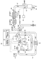
図1は、本発明の内燃機関の排気浄化システムを備えたディーゼルエンジンの全体構成図である。まず、図1を参照して、本発明の内燃機関の排気浄化装置の全体構成について説明する。 FIG. 1 is an overall configuration diagram of a diesel engine equipped with an exhaust gas purification system for an internal combustion engine according to the present invention. First, with reference to FIG. 1, the overall configuration of an exhaust emission control device for an internal combustion engine of the present invention will be described.
図1に示すように、本発明の排気浄化システムを備えたディーゼルエンジンは、エンジン1、排気通路3、給気通路13、可変ターボ過給機11、コモンレール燃料噴射装置18、EGR管23などの各種装置・配管、酸化触媒(DOC装置)5、ディーゼルパティキュレートフィルタ(DPF装置)7、選択的還元触媒(SCR装置)9などの各種排気浄化装置、およびこれらを制御するエンジンコントローラユニット(ECU)19と各種センサなどから構成されている。
As shown in FIG. 1, a diesel engine equipped with an exhaust purification system of the present invention includes an
エンジン1の下流側には排気通路3が接続されており、排気通路3には、DOC装置5およびDPF装置7が設けられている。DOC装置5は、排気ガス中の炭化水素(HC)や一酸化炭素(CO)を酸化除去するとともに、排気ガス中の一酸化窒素(NO)を酸化して二酸化窒素(NO2)を生成する機能を有する。DPF装置7は、DOC装置5の下流側に設けられ、排気ガス中に含まれるススなどの排気微粒子(PM)をフィルタで捕集し、排気ガスから除去する装置である。
An
また、DPF装置7の下流側には尿素水噴射装置8が設けられ、該尿素水噴射装置8の直下流にはSCR装置9が設けられている。尿素水噴射装置8は、ECU19からの制御信号に基づいて、尿素水タンク8bに貯留されている尿素水を噴射ノズル8aから排気通路3に向けて噴射する。排気通路3に噴射された尿素水は、排気ガス27の熱により加水分解されてアンモニア(NH3)を生成し、この生成されたアンモニア(NH3)が還元剤となって、SCR装置9において排気ガス27に含まれるNOXの還元が行われる。
Further, a urea water injection device 8 is provided on the downstream side of the DPF device 7, and an
これらDOC装置5およびSCR装置9において排気ガスの浄化を進行させるためには、DOC装置5およびSCR装置9に担持されている触媒を活性温度以上に加熱する必要がある。また、DPF装置7において、フィルタに捕集されたPMを除去してフィルタを再生するためには、DPF装置7を所定以上の温度に加熱する必要がある。すなわち、これら排気浄化装置において十分な浄化機能が発揮されるためには、排気浄化装置を所定以上の温度に加熱する必要がある。本発明の内燃機関の排気浄化システムでは、これら排気浄化装置の昇温を図る手段として、後述する空気流量制御手段50を有している。
In order for the DOC device 5 and the
一方、エンジン1の上流側には、給気通路13が接続されている。そして、給気通路13と排気通路3との間には、可変ターボ過給機11が設けられている。この可変ターボ過給機11は、排気通路3に配置されている排気タービン11bと、給気通路13に配置されているコンプレッサ11aとを有しており、該コンプレッサ11aは排気タービン11bによって同軸駆動されるようになっている。また、この可変ターボ過給機11は、ECU19からの制御信号に基づいて、可変ノズルベーン(不図示)の開度や、ウエストゲートバルブ(不図示)の開度が調整されることで、コンプレッサ11aから吐出される空気26の流量を制御できるようになっている。
On the other hand, an
また、給気通路13にはインタークーラ15および給気スロットルバルブ17が設けられている。そして、コンプレッサ11aから吐出された空気26は、インタークーラ15で冷却された後、給気スロットバルブ17を通過して、エンジン1の各気筒内の燃焼室1aに流入するようになっている。この際、給気スロットルバルブ17は、ECU19からの制御信号に基づいてその開度が調整されることで、エンジン1に供給される給気流量を制御するようになっている。
In addition, an
また、エンジン1には、燃焼室1aに燃料を噴射するコモンレール燃料噴射装置18が設けられている。このコモンレール燃料噴射装置18は、ECU19からの制御信号に基づいて、噴射時期および噴射量が制御されるようになっている。後述する噴射タイミング制御は、ECU19からの制御信号に基づき、コモンレール燃料噴射装置18から燃焼室1aに噴射する燃料の噴射量および噴射時期を、通常運転モードとは異なるように制御することで行われる。
Further, the
また、排気通路3の排気タービン11bの上流側よりEGR管23が分岐し、給気スロットルバルブ17の下流側に接続している。また、EGR管23には、EGRクーラ24とともに、EGRバルブ25が配置されている。そして、EGRバルブ25を開閉制御することにより、エンジン1から排出された排気ガス27の一部が、EGR管23を通ってエンジン1を再循環するようになっている。
Further, the
エンジン1から排出された排気ガス27は、排気通路3を通って、上述した排気タービン11bを駆動してコンプレッサ11aを同軸駆動させる。そして、排気通路3を通過し、上述したDOC装置5、DPF装置7、SCR装置9を通過する。また、給気通路13には、コンプレッサ11aへ流入する空気流量を検出するエアフローメータ31が配置されており、該エアフローメータ31にて測定された給気流量に関する信号が、ECU19へと入力されるようになっている。
The
また、排気通路3には、DOC入口温度センサ35、DPF入口圧力センサ36、DPF入口温度センサ37、DPF差圧センサ38、およびDPF出口温度センサ39が配置されている。そして、これらセンサ類で測定されたDOC入口温度、DPF入口温度、DPF出口温度などに関する信号が、ECU19へと入力されるようになっている。また、SCR装置9の下流側にも、SCR出口温度センサ33およびNOXセンサ34が配置されている。そして、これらSCR出口温度センサ33およびNOXセンサ34で測定されたSCR装置9の下流側における温度およびNOX濃度に関する信号が、ECU19へと入力されるようになっている。
A DOC
また、給気スロットルバルブ17の下流側には、給気温度センサ41および給気圧力センサ43が配置されている。そして、該給気温度センサ41にて測定された給気温度、および該給気圧力センサ43で測定された給気圧力に関する信号が、ECU19へと入力されるようになっている。そして、ECU19において、これら給気温度、給気圧力などに基づいて最適なEGR量を算出することで、上述したEGRバルブ25の開閉制御が行われるようになっている。
An air
また、ECU19では、不図示のクランクセンサ、カムセンサ、アクセルセンサ、スロットルセンサ等の各種センサからの入力信号を基に、エンジン回転数および燃料噴射量が算出されるようになっている。また、エンジン1の周囲には不図示の冷却水通路が形成されるとともに、該冷却水通路を流れるエンジン冷却水の水温を測定する冷却水温度測定手段(不図示)が配置されている。
The
ECU19は、中央処理装置(CPU)、ランダムアクセスメモリ(RAM)、リードオンリメモリ(ROM)、およびI/Oインターフェイスなどからなるマイクロコンピュータで構成されている。上述したセンサ類からの各種信号は、I/Oインターフェイスを介してCPUに入力される。CPUでは、ROMに記憶されている制御プログラムに従って、各種制御を実行するように構成されている。そして、図1に示すように、該ECU19によって、本発明の空気流量制御手段50、および作動タイミング制御手段52が構成されている。
The
図2は、本発明の空気流量制御手段50を示したブロック図である。本実施形態の空気流量制御手段50は、作動タイミング制御手段52からの指令に基づいて、上述した給気スロットル17および可変ターボ過給機11の開度を制御し、エンジン1に供給される空気流量を制御(低減)することができるように構成されている。なお、本発明の空気流量制御手段50は、必ずしも給気スロットル17および可変ターボ過給機11の両方を制御するように構成されていなくともよく、エンジン1に供給される空気流量を制御(低減)することが可能であれば、いずれか一方だけを制御するように構成されていてもよいものである。
FIG. 2 is a block diagram showing the air flow rate control means 50 of the present invention. The air flow rate control means 50 of the present embodiment controls the opening degree of the above-described
空気流量制御は昇温効果が高く、エンジン始動直後などの暖機運転時において、排気浄化装置の早期の昇温を図る上で極めて有効である。その一方、上述した図19において説明したように、空気流量制御を行うと気筒内の圧力が低下するため、エンジン始動後のあまり早いタイミングで空気流量制御を実施すると、エンジンの燃焼状態が不安定になってしまう。 The air flow rate control is highly effective in raising the temperature, and is extremely effective in raising the temperature of the exhaust emission control device early during warm-up operation such as immediately after engine startup. On the other hand, as described above with reference to FIG. 19, when the air flow control is performed, the pressure in the cylinder decreases. Therefore, if the air flow control is performed too early after the engine is started, the combustion state of the engine is unstable. Become.
このため本発明では、作動タイミング制御手段52によって空気流量制御手段50が作動するタイミングを制御することで、空気流量制御が実施されても、エンジン1の燃焼状態が不安定とならないように構成されている。
以下、本発明の作動タイミング制御手段52の実施形態について、具体的に説明する。
For this reason, the present invention is configured so that the combustion state of the
Hereinafter, embodiments of the operation timing control means 52 of the present invention will be specifically described.
<第1の実施形態>
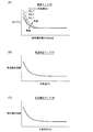
図3は、第1の実施形態を説明するための概念図であり、図3(A)は、空気流量制御を開始するタイミングとエンジン燃焼状態との関係を示した図、図3(B)は、エンジン運転時間と、SCR触媒担体温度との関係を示した図である。
この第1の実施形態の作動タイミング制御手段52は、図3に示したように、エンジン1の始動後、噴射タイミング制御(i)を実施するとともに、エンジン1の暖機運転(ii)を行うようになっている。そして、エンジン1の始動から所定時間(t1)が経過した後に、空気流量制御(iii)を実施するように構成されている。
<First Embodiment>
FIG. 3 is a conceptual diagram for explaining the first embodiment. FIG. 3A is a diagram showing the relationship between the timing of starting air flow control and the engine combustion state, and FIG. These are the figures which showed the relationship between engine operation time and SCR catalyst support | carrier temperature.
As shown in FIG. 3, the operation timing control means 52 of the first embodiment performs the injection timing control (i) and the
上記所定時間(t1)は、図5に示すように、エンジン1のエンジン回転数(Ne)および燃料噴射量(Qf)を入力データとする標準マップ56によって算出された標準時間(t1´)に、外気温を入力データとする温度補正マップ57によって算出される温度補正係数、および大気圧を入力データとする気圧補正マップ58によって算出される気圧補正係数を乗じて算出される(温度・気圧補正)。これら標準マップ56、温度補正マップ57、気圧補正マップ58は、実験等を行うことによって作成され、予めECU19のROMに記憶されている。
As shown in FIG. 5, the predetermined time (t1) is a standard time (t1 ′) calculated by a
本実施形態において、上述した温度補正および気圧補正は、いずれか一方だけ実施するようにしてもよく、また両方とも実施しなくてもよいものである。温度補正および気圧補正の両方とも実施しない場合は、図5において、標準時間(t1´)がそのまま所定時間(t1)となる。 In the present embodiment, only one of the above-described temperature correction and atmospheric pressure correction may be performed, or both may not be performed. When neither the temperature correction nor the atmospheric pressure correction is performed, the standard time (t1 ′) in FIG. 5 becomes the predetermined time (t1) as it is.
ここで、エンジン回転数(Ne)と標準時間(t1´)との関係は、図4(A)に示すように、エンジン回転数(Ne)が高いほど標準時間(t1´)は短くなり、反対に、エンジン回転数(Ne)が低いほど標準時間(t1´)は長くなる。また、燃料噴射量(Qf)と標準時間(t1´)との関係は、燃料噴射量(Qf)が多いほど標準時間(t1´)は短くなり、反対に、燃料噴射量(Qf)が少ないほど標準時間(t1´)は長くなる。また、図4(B)に示すように、外気温が高いほど気温補正係数は小さくなり、図4(C)に示すように、大気圧が高いほど気圧補正係数は小さくなる。 Here, as shown in FIG. 4A, the relationship between the engine speed (Ne) and the standard time (t1 ′) is such that the higher the engine speed (Ne), the shorter the standard time (t1 ′). On the contrary, the standard time (t1 ′) becomes longer as the engine speed (Ne) is lower. Further, the relationship between the fuel injection amount (Qf) and the standard time (t1 ′) is that the standard time (t1 ′) becomes shorter as the fuel injection amount (Qf) increases, and conversely, the fuel injection amount (Qf) decreases. The standard time (t1 ′) becomes longer as it goes. As shown in FIG. 4B, the higher the outside air temperature, the smaller the temperature correction coefficient. As shown in FIG. 4C, the higher the atmospheric pressure, the smaller the atmospheric pressure correction coefficient.
図6は、第1の実施形態における制御フロー図である。この図6に示したように、第1の実施形態における作動タイミング制御手段52は、エンジン始動後(S10)、噴射タイミング制御を実施し(S11)、エンジンの昇温を行う。そして、上述した図5に示したように、空気流量制御を開始する時間(所定時間:t1)を算出する(S12)。そして、算出された所定時間(t1)を記憶するとともに(S13)、記憶した所定時間(t1)と経過時間(t)とを比較し(S14)、t≧t1の場合(S14においてYes)には、空気流量制御を実施する(S15)。一方、t<t1の場合(S14においてNo)は、空気流量制御は実施せずに、S12に戻る。 FIG. 6 is a control flow diagram in the first embodiment. As shown in FIG. 6, the operation timing control means 52 in the first embodiment performs the injection timing control after the engine is started (S10) and raises the temperature of the engine. Then, as shown in FIG. 5 described above, a time (predetermined time: t1) for starting the air flow rate control is calculated (S12). The calculated predetermined time (t1) is stored (S13), the stored predetermined time (t1) is compared with the elapsed time (t) (S14), and if t ≧ t1 (Yes in S14). Performs air flow control (S15). On the other hand, when t <t1 (No in S14), the flow returns to S12 without performing the air flow rate control.
このように、第1の実施形態における作動タイミング制御手段52は、エンジン1の始動から所定時間(t1)が経過した後に、空気流量制御手段50を作動させるように構成されている。当該所定時間(t1)は、図5に示したように、エンジン1のエンジン回転数(Ne)および燃料噴射量(Qf)を入力データとする標準マップ56によって算出される。また、必要に応じて、エンジン1が作動している状態の外気温および大気圧によって補正されることで算出される。
As described above, the operation timing control means 52 in the first embodiment is configured to operate the air flow rate control means 50 after a predetermined time (t1) has elapsed since the start of the
このような第1の実施形態によれば、エンジン始動直後における排気浄化装置の昇温と、HC排出量の増加抑制とを、簡易的な方法で制御することができる。またこの際、外気温および/または大気圧に応じて所定時間を補正するため、外気温や大気圧に応じて精度よく空気流量制御手段50を作動させるタイミングを決定することができる。 According to the first embodiment, it is possible to control the temperature increase of the exhaust gas purification apparatus immediately after engine startup and the suppression of the increase in the HC emission amount by a simple method. At this time, since the predetermined time is corrected according to the outside air temperature and / or the atmospheric pressure, the timing for operating the air flow control means 50 with high accuracy can be determined according to the outside air temperature and the atmospheric pressure.
<第2の実施形態>
図7は、第2の実施形態を説明するための概念図であり、図7(A)は、空気流量制御を開始するタイミングとエンジン燃焼状態との関係を示した図、図7(B)は、エンジン運転時間と、SCR触媒担体温度および冷却水温度との関係を示した図である。第2の実施形態の作動タイミング制御手段52は、図7に示したように、エンジン1の始動後、噴射タイミング制御(i)を実施するとともに、エンジン1の暖機運転(ii)を行うようになっている。そして、エンジン冷却水が所定の冷却水温度(tw1)に到達した後に、空気流量制御(iii)を実施するように構成されている。なお、エンジン冷却水温度は、上述した不図示の冷却水温測定手段などによって把握することができる。
<Second Embodiment>
FIG. 7 is a conceptual diagram for explaining the second embodiment. FIG. 7A is a diagram showing the relationship between the timing of starting the air flow control and the engine combustion state, and FIG. These are the figures which showed the relationship between engine operation time, SCR catalyst support | carrier temperature, and cooling water temperature. As shown in FIG. 7, the operation timing control means 52 of the second embodiment performs the injection timing control (i) and the
上記所定の冷却水温度(tw1)は、図9に示すように、エンジン1のエンジン回転数(Ne)および燃料噴射量(Qf)を入力データとする標準マップ66によって算出された標準冷却水温度(tw1´)に、外気温を入力データとする温度補正マップ67によって算出される温度補正係数、および大気圧を入力データとする気圧補正マップ68によって算出される気圧補正係数を乗じて算出される(温度・気圧補正)。これら標準マップ66、温度補正マップ67、気圧補正マップ68は、実験等を行うことによって作成され、予めECU19のROMに記憶されている。
As shown in FIG. 9, the predetermined coolant temperature (tw1) is a standard coolant temperature calculated by a
本実施形態においても、上述した温度補正および気圧補正は、いずれか一方だけ実施するようにしてもよく、また両方とも実施しなくてもよいものである。温度補正および気圧補正の両方とも実施しない場合は、図9において、標準冷却水温度(tw1´)がそのまま所定の冷却水温度(tw1)となる。 Also in the present embodiment, only one of the above-described temperature correction and atmospheric pressure correction may be performed, or both may not be performed. When neither the temperature correction nor the atmospheric pressure correction is performed, the standard cooling water temperature (tw1 ′) in FIG. 9 becomes the predetermined cooling water temperature (tw1) as it is.
ここで、エンジン回転数(Ne)と標準冷却水温度(tw1´)との関係は、図8(A)に示すように、所定の燃料噴射量までは、エンジン回転数(Ne)が高いほど標準冷却水温度(tw1´)は低くなり、反対に、エンジン回転数(Ne)が低いほど標準冷却水温度(tw1´)は高くなる。また、燃料噴射量(Qf)と標準冷却水温度(tw1´)との関係は、所定の燃料噴射量までは、燃料噴射量(Qf)が多いほど標準冷却水温度(tw1´)は低くなり、反対に、燃料噴射量(Qf)が少ないほど標準冷却水温度(tw1´)は高くなる。燃料噴射量(Qf)が前記所定値を超えると、エンジン回転数(Ne)に関わらず、標準冷却水温度(tw1´)はほぼ一定となる。また、図8(B)に示すように、外気温が高いほど気温補正係数は小さくなり、図8(C)に示すように、大気圧が高いほど気圧補正係数は小さくなる。 Here, as shown in FIG. 8A, the relationship between the engine speed (Ne) and the standard coolant temperature (tw1 ′) is such that, as the engine speed (Ne) is higher, up to a predetermined fuel injection amount. The standard cooling water temperature (tw1 ′) decreases, and conversely, the lower the engine speed (Ne), the higher the standard cooling water temperature (tw1 ′). In addition, the relationship between the fuel injection amount (Qf) and the standard cooling water temperature (tw1 ′) indicates that the standard cooling water temperature (tw1 ′) decreases as the fuel injection amount (Qf) increases up to a predetermined fuel injection amount. On the contrary, the standard coolant temperature (tw1 ′) increases as the fuel injection amount (Qf) decreases. When the fuel injection amount (Qf) exceeds the predetermined value, the standard coolant temperature (tw1 ′) becomes substantially constant regardless of the engine speed (Ne). As shown in FIG. 8B, the higher the outside air temperature, the smaller the temperature correction coefficient. As shown in FIG. 8C, the higher the atmospheric pressure, the smaller the atmospheric pressure correction coefficient.
図10は、第2の実施形態における制御フロー図である。この図10に示したように、第2の実施形態における作動タイミング制御手段52は、エンジン始動後(S20)、噴射タイミング制御を実施し(S21)、エンジンの昇温を行う。そして、上述した図9に示したように、空気流量制御を開始する所定の冷却水温度(tw1)を算出する(S22)。そして、算出された所定の冷却水温度(tw1)と不図示の冷却水温度測定手段で測定した冷却水温度(tw)とを比較する(S23)。そして、tw≧tw1の場合(S23においてYes)に、空気流量制御を実施する(S24)。一方、tw<tw1の場合(S23においてNo)は、空気流量制御は実施せずに、S22に戻る。 FIG. 10 is a control flow diagram in the second embodiment. As shown in FIG. 10, the operation timing control means 52 in the second embodiment performs injection timing control after the engine is started (S20) and raises the temperature of the engine. Then, as shown in FIG. 9 described above, a predetermined cooling water temperature (tw1) for starting the air flow rate control is calculated (S22). Then, the calculated predetermined coolant temperature (tw1) is compared with the coolant temperature (tw) measured by the coolant temperature measuring means (not shown) (S23). Then, if tw ≧ tw1 (Yes in S23), air flow control is performed (S24). On the other hand, if tw <tw1 (No in S23), the air flow rate control is not performed and the process returns to S22.
このように、第2の実施形態における作動タイミング制御手段52は、エンジン1を冷却するエンジン冷却水の温度が閾値(所定の冷却水温度:tw1)以上になった場合に、空気流量制御手段50を作動させるように構成されている。所定の冷却水温度(tw1)は、図9に示したように、エンジン1のエンジン回転数(Ne)および燃料噴射量(Qf)を入力データとする標準マップ66によって算出される。また、必要に応じて、エンジン1が作動している状態の外気温および大気圧によって補正されることで算出される。また、エンジン冷却水温度は、上述した冷却水温測定手段などによって把握することができる。
As described above, the operation timing control means 52 in the second embodiment is configured such that the air flow rate control means 50 when the temperature of the engine cooling water for cooling the
また、上述したエンジン冷却水の温度に替えて、前記エンジン内部を通過する潤滑油の温度によって、エンジン1の燃焼状態を把握することもできる。すなわち、エンジン1の内部を通過する潤滑油の温度が閾値以上になった場合に、空気流量制御手段50を作動させるように構成することもできる。この際、所定の潤滑油温度(閾値)は、上述したエンジン冷却水の場合と同様、エンジン1のエンジン回転数(Ne)および燃料噴射量(Qf)を入力データとする標準マップによって算出することができる。また、上述したエンジン冷却水の場合と同様、必要に応じて、エンジン1が作動している状態の外気温および大気圧によって補正することで算出してもよい。また、潤滑油温度は、潤滑経路上の適当な位置に配置された温度センサー(不図示)などによって把握することができる。
Further, the combustion state of the
このような第2の実施形態によれば、エンジン冷却水の温度もしくは潤滑油温度からエンジン1の燃焼状態を把握することで、空気流量制御手段50が作動するタイミングを制御することができる。よって、エンジン1の安定燃焼を確保しつつ、早期に排気浄化装置の昇温を図ることができる。またこの際、外気温および/または大気圧に応じて冷却水温度もしくは潤滑油温度の閾値を補正することで、外気温や大気圧に応じて精度よく空気流量制御手段50を作動させるタイミングを決定することができる。
According to such 2nd Embodiment, the timing which the air flow control means 50 act | operates can be controlled by grasping | ascertaining the combustion state of the
<第3の実施形態>
図11は、第3の実施形態を説明するための概念図であり、空気流量制御を開始するタイミングとエンジン燃焼状態との関係を示している。この第3の実施形態の作動タイミング制御手段52は、エンジン1の始動後、噴射タイミング制御(i)を実施するとともに、エンジン1の暖機運転(ii)を行うようになっている。そして、エンジン1の燃焼状態が「安定燃焼」にあることを確認した後に、空気流量制御(iii)を実施するように構成されている。
<Third Embodiment>
FIG. 11 is a conceptual diagram for explaining the third embodiment, and shows the relationship between the timing of starting the air flow rate control and the engine combustion state. The operation timing control means 52 of the third embodiment performs the injection timing control (i) and the warm-up operation (ii) of the
ここで本実施形態における「安定燃焼」とは、空気流量制御(iii)を実施しても、エンジン1の燃焼状態が安定状態にあることを言う。すなわち、図11において符号a´で示したエンジンの燃焼状態は本実施形態で言うところの安定燃焼ではなく、符号aで示したエンジンの燃焼状態において、はじめて本実施形態で言うところの安定燃焼と判断される。
Here, “stable combustion” in the present embodiment means that the combustion state of the
エンジン1の燃焼状態が「安定燃焼」にあるか否かの判断は、図12に示したように、燃料噴射タイミング(θ)における気筒内温度(Tcyl)および気筒内圧力(Pcyl)を入力データとする安定燃焼判断マップ76によって判断される。燃料噴射タイミング(θ)における気筒内温度(Tcyl)は、給気温度センサ41で測定された給気温度と、燃料噴射タイミング(θ)とから演算(推定)される。また、燃料噴射タイミング(θ)における気筒内圧力(Pcyl)は、給気圧力センサ43で測定された給気圧力と、燃料噴射タイミング(θ)とから演算(推定)される。また、燃料噴射タイミング(θ)は、エンジン回転数(Ne)と燃料噴射量(Qf)とを入力データとするマップ78によって算出される。
Whether or not the combustion state of the
図13は、第3の実施形態における制御フロー図である。この図13に示したように、第3の実施形態における作動タイミング制御手段52は、エンジン始動後(S30)、噴射タイミング制御を実施し(S31)、エンジンの昇温を行う。そして、上述した図12に示したように、燃料噴射タイミング(θ)における気筒内温度(Tcyl)、および気筒内圧力(Pcyl)を算出する(S32、S33)。なお、S32とS33は、その順番が逆でも構わないし、同時であってもよいものである。そして、上述した安定燃焼マップ76によって、給気流量制御後のエンジン1の「安定燃焼」の可否を判断する(S34)。安定燃焼可と判断された場合(S34においてYes)は、空気流量制御を実施する(S35)。一方、安定燃焼否と判断された場合(S34においてNo)は、空気流量制御は実施せず、S32に戻る。
FIG. 13 is a control flow diagram in the third embodiment. As shown in FIG. 13, the operation timing control means 52 in the third embodiment performs injection timing control after the engine is started (S30) and raises the temperature of the engine. Then, as shown in FIG. 12, the in-cylinder temperature (T cyl ) and the in-cylinder pressure (P cyl ) at the fuel injection timing (θ) are calculated (S32, S33). Note that the order of S32 and S33 may be reversed or simultaneous. Then, based on the
このように、第3の実施形態における作動タイミング制御手段52は、エンジン1の気筒内の温度および圧力を推定し、この推定された気筒内の温度および圧力に基づいて、空気流量制御後の気筒内が「安定燃焼」状態にあるか否かを判断した後に、空気流量制御手段50を作動させるようになっている。
As described above, the operation timing control means 52 in the third embodiment estimates the temperature and pressure in the cylinder of the
したがって、このような第3の実施形態によれば、空気流量制御を実施した後のエンジン1の燃焼状態を精度よく推定した上で、空気流量制御手段50が作動するタイミングを制御するため、エンジン1の安定燃焼を確保しつつ、早期に排気浄化装置の昇温を図ることができるようになっている。
Therefore, according to the third embodiment, since the combustion state of the
<第4の実施形態>
図14は、第4の実施形態を説明するための概念図であり、図14(A)は、空気流量制御を開始するタイミングとエンジン燃焼状態との関係を示した図、図14(B)は、エンジン運転時間と、気筒内最高圧力変動率(Pmax−COV)、可変ターボ過給機のベーン開度、SCR触媒担体温度との関係を示した図であり、可変ターボ過給機11のベーン開度を調整することで、空気流量制御を行っている例を示している。
この第4の実施形態の作動タイミング制御手段52は、気筒内の圧力を測定する気筒内圧測定手段(不図示)を有している。そして、エンジン1の始動後、噴射タイミング制御(i)を実施した後に、気筒内圧測定手段によって気筒内の圧力をセンシングし、エンジン1の燃焼状態を安定状態に保ちながら、空気流量制御(ii)を実施するように構成されている。
<Fourth Embodiment>
FIG. 14 is a conceptual diagram for explaining the fourth embodiment. FIG. 14A is a diagram showing the relationship between the timing of starting air flow control and the engine combustion state, and FIG. 14B. These are the figures which showed the relationship between engine operating time, in-cylinder maximum pressure fluctuation rate ( Pmax-COV ), the vane opening degree of a variable turbocharger, and SCR catalyst carrier temperature, and
The operation timing control means 52 of the fourth embodiment has cylinder internal pressure measuring means (not shown) for measuring the pressure in the cylinder. Then, after the
エンジン1の燃焼状態が安定状態か否かの判断は、例えば、気筒内最高圧力(Pmax)の変動率(cov)から判断することができる。すなわち、ある特定期間のサイクルにおける気筒内最高圧力の標準偏差σ(Pmax)と、気筒内最高圧力の算術平均値(Pmax_avg)とから、気筒内最高圧力変動率(Pmax−COV)を下記式(1)により求め、この気筒内最高圧力変動率(Pmax−COV)が、あらかじめECU19のROMに記憶されている閾値(例えば1%)を超えない場合は、燃焼状態が安定状態にあると判断することができる。
Pmax−COV=(σ(Pmax))/(Pmax_avg) ・・・(1)
The determination as to whether or not the combustion state of the
P max−COV = (σ (P max )) / (P max — avg ) (1)
図15は、第4の実施形態における制御フロー図である。この図15に示したように、第4の実施形態における作動タイミング制御手段52は、エンジン始動後(S40)、噴射タイミング制御を実施し(S41)、エンジンの昇温を行う。そして、上述した気筒内圧測定手段によって気筒内最高圧力(Pmax)を検出するとともに(S42)、気筒内最高圧力変動率(Pmax−COV)を算出する(S43)。そして、算出した気筒内最高圧力変動率(Pmax−COV)が閾値以下の場合(S44においてYes)は、空気流量制御が開始される(S45)。空気流量制御では、例えば可変ターボ過給機11のベーン開度が徐々に調整されることで、エンジン1に供給される空気流量が緩やかに低減される。一方、算出した気筒内最高圧力変動率(Pmax−COV)が閾値より大きい場合(S44においてNo)は、空気流量制御は実施せずに、S42に戻る。
FIG. 15 is a control flow diagram according to the fourth embodiment. As shown in FIG. 15, the operation timing control means 52 in the fourth embodiment performs injection timing control after the engine is started (S40) and raises the temperature of the engine. Then, the cylinder internal pressure (P max ) is detected by the cylinder internal pressure measuring means (S42), and the cylinder maximum pressure fluctuation rate (P max−COV ) is calculated (S43). When the calculated in-cylinder maximum pressure fluctuation rate (P max−COV ) is equal to or less than the threshold value (Yes in S44), the air flow rate control is started (S45). In the air flow rate control, for example, the air flow rate supplied to the
空気流量制御(S45)の開始後は、空気流量制御中の気筒内最高圧力変動率(Pmax−COV)を算出して閾値との比較を行う(S46)。そして、気筒内最高圧力変動率(Pmax−COV)が閾値を下回る場合(S46においてYes)は、空気流量が目標制御量に到達したか否かが判定され(S47)、目標制御量に到達した場合は、そこで空気流量制御が終了(S48)し、空気流量が目標制御量に到達していない場合は、S45に戻って空気流量制御が継続される。一方、気筒内最高圧力変動率(Pmax−COV)が閾値より大きい場合(S46においてNo)は、空気流量制御を中断(S49)してS42に戻る。 After the start of air flow control (S45), the in-cylinder maximum pressure fluctuation rate ( Pmax-COV ) during air flow control is calculated and compared with a threshold value (S46). If the in-cylinder maximum pressure fluctuation rate (P max−COV ) is lower than the threshold value (Yes in S46), it is determined whether or not the air flow rate has reached the target control amount (S47), and the target control amount is reached. If the air flow rate control has ended, the air flow rate control ends (S48). If the air flow rate has not reached the target control amount, the flow returns to S45 to continue the air flow rate control. On the other hand, when the cylinder maximum pressure fluctuation rate (P max -COV ) is larger than the threshold value (No in S46), the air flow control is interrupted (S49) and the process returns to S42.
なお、上記説明では、可変ターボ過給機11のベーン開度を徐々に調整することで、エンジン1に供給される空気流量が緩やかに低減される場合を例に説明した。しかしながら本実施形態はこれに限定されず、例えば、図16に示したように、給気スロットルバルブ17の開度を段階的に絞ることで、エンジン1に供給される空気流量を階段状に制御することも可能である。この場合の制御フローは、図17に示すとおりである。すなわち、空気流量制御が段階的に行われるため、図15における空気流量制御の開始(S45)および空気流量制御を中断(S49)が、図17では一つのステップとして表記され、空気流量制御の実施(S45´)として表される。
In the above description, the case where the flow rate of air supplied to the
また、上記説明では、エンジン1の燃焼状態の判断を、気筒内最高圧力変動率(Pmax−cov)から判断していたが、本実施形態はこれに限定されない。例えば、上述した気筒内圧測定手段によって図示平均圧力(IMEP)を算出し、このIMEPの変動率によって、エンジンの燃焼状態を判断するようにしてもよいものである。
In the above description, the combustion state of the
このように、第4の実施形態における作動タイミング制御手段52は、エンジン1の気筒内の圧力を測定する気筒内圧測定手段(不図示)を有しており、該気筒内圧測定手段によって測定された気筒内の圧力に基づいて、エンジン1の燃焼状態をリアルタイムで計測しながら、空気流量制御手段50が作動するタイミングが制御されるようになっている。
As described above, the operation timing control means 52 in the fourth embodiment has the cylinder internal pressure measuring means (not shown) for measuring the pressure in the cylinder of the
したがって、このような第4の実施形態によれば、気筒内圧測定手段によってエンジン1の燃焼安定性をリアルタイムに直接的に把握しながら、空気流量制御手段50の作動タイミングを制御することができるため、エンジン1の安定燃焼を確保しつつ、早期に排気浄化装置の昇温を図ることができるようになっている。
Therefore, according to the fourth embodiment, it is possible to control the operation timing of the air flow rate control means 50 while directly grasping the combustion stability of the
以上、本発明の好ましい形態について説明したが、本発明は上記の形態に限定されるものではなく、本発明の目的を逸脱しない範囲での種々の変更が可能である。 As mentioned above, although the preferable form of this invention was demonstrated, this invention is not limited to said form, A various change in the range which does not deviate from the objective of this invention is possible.
例えば、上述した実施形態の説明では、空気流量制御手段50によって昇温される排気浄化装置として、SCR装置9を例に説明した。しかしながら、本発明の排気浄化装置としては、SCR装置の他に、DOC装置5やDPF装置7などが挙げられる。本発明は、これらDOC装置5およびDPF装置7を備える内燃機関の排気浄化システムとしても、好適に用いられるものである。
For example, in the above description of the embodiment, the
また、上述した実施形態の説明では、空気流量制御の実施に先立って、噴射タイミング制御が実施されるものとして説明したが、本発明において、噴射タイミング制御の実施は必須ではない。 In the above description of the embodiment, it has been described that the injection timing control is performed prior to the air flow rate control. However, in the present invention, the injection timing control is not essential.
本発明によれば、DOCやDPF、SCRなどの排気浄化装置を備えたディーゼルエンジンの排気浄化システムとして、好適に用いることができる。 ADVANTAGE OF THE INVENTION According to this invention, it can use suitably as an exhaust gas purification system of the diesel engine provided with exhaust gas purification apparatuses, such as DOC, DPF, and SCR.
1 エンジン
3 排気通路
5 DOC装置
7 DPF装置
8 尿素水噴射装置
9 SCR装置
11 可変ターボ過給機
13 給気通路
15 インタークーラ
17 給気スロットルバルブ
18 コモンレール燃料噴射装置
19 ECU
23 EGR管
24 EGRクーラ
25 EGRバルブ
26 空気
27 排気ガス
31 エアフローメータ
33 SCR出口温度センサ
34 NOXセンサ
35 DOC入口温度センサ
36 DPF入口圧力センサ
37 DPF入口温度センサ
38 DPF差圧センサ
39 DPF出口温度センサ
41 給気温度センサ
43 給気圧力センサ
50 空気流量制御手段
52 作動タイミング制御手段
1
23
Claims (2)
前記エンジンに供給される空気流量を低減することで前記エンジンから排出される排気ガスの昇温を図る空気流量制御手段と、該空気流量制御手段が作動するタイミングを制御する作動タイミング制御手段とを有し、
前記作動タイミング制御手段は、前記エンジンの始動後、燃料を噴射するタイミングを変更する噴射タイミング制御を実施した後に、前記空気流量制御手段が作動して前記エンジンに供給される空気流量が低減されても、前記エンジンの燃焼状態が不安定とならないように、前記空気流量制御手段が作動するタイミングを制御するように構成され、
前記空気流量制御手段は、前記排気通路に配置される排気タービンと、前記エンジンに供給される空気が通過する給気通路に配置されるコンプレッサと、を有する可変ターボ過給機からなり、前記エンジンの気筒内の圧力を測定する気筒内圧測定手段を有しており、該気筒内圧測定手段によって測定された気筒内の圧力の変動率が予め定められた閾値を超えないように、前記可変ターボ過給機の可変ノズルベーンのベーン開度を徐々に調整することで、前記エンジンに供給される空気流量を緩やかに低減するように構成されていることを特徴とする内燃機関の排気浄化システム。 In an exhaust purification system of an internal combustion engine comprising an engine, an exhaust passage through which exhaust gas discharged from the engine passes, and an exhaust purification device installed in the exhaust passage,
An air flow rate control means for increasing the temperature of exhaust gas discharged from the engine by reducing an air flow rate supplied to the engine; and an operation timing control means for controlling the timing at which the air flow rate control means is activated. Have
The operation timing control means performs an injection timing control for changing a fuel injection timing after the engine is started, and then the air flow control means is operated to reduce an air flow rate supplied to the engine. Is configured to control the timing at which the air flow control means is operated so that the combustion state of the engine does not become unstable.
The air flow rate control means includes a variable turbocharger having an exhaust turbine disposed in the exhaust passage and a compressor disposed in an air supply passage through which air supplied to the engine passes. Cylinder pressure measuring means for measuring the pressure in the cylinder, and the variable turbo pressure so that the fluctuation rate of the pressure in the cylinder measured by the cylinder pressure measuring means does not exceed a predetermined threshold value. An exhaust gas purification system for an internal combustion engine, characterized in that the flow rate of air supplied to the engine is gradually reduced by gradually adjusting the vane opening degree of the variable nozzle vane of the feeder .
Priority Applications (6)
| Application Number | Priority Date | Filing Date | Title |
|---|---|---|---|
| JP2011251048A JP5986736B2 (en) | 2011-11-16 | 2011-11-16 | Exhaust gas purification system for internal combustion engine |
| CN201280049773.8A CN103874833B (en) | 2011-11-16 | 2012-11-06 | The emission control system of internal combustion engine |
| PCT/JP2012/078674 WO2013073409A1 (en) | 2011-11-16 | 2012-11-06 | Exhaust purification system for internal combustion engine |
| EP12849177.6A EP2781711B1 (en) | 2011-11-16 | 2012-11-06 | Exhaust gas purification system for internal combustion engine |
| IN3066DEN2014 IN2014DN03066A (en) | 2011-11-16 | 2012-11-06 | |
| US14/352,542 US9512785B2 (en) | 2011-11-16 | 2012-11-06 | Exhaust gas purification system for internal combustion engine |
Applications Claiming Priority (1)
| Application Number | Priority Date | Filing Date | Title |
|---|---|---|---|
| JP2011251048A JP5986736B2 (en) | 2011-11-16 | 2011-11-16 | Exhaust gas purification system for internal combustion engine |
Publications (2)
| Publication Number | Publication Date |
|---|---|
| JP2013104415A JP2013104415A (en) | 2013-05-30 |
| JP5986736B2 true JP5986736B2 (en) | 2016-09-06 |
Family
ID=48429473
Family Applications (1)
| Application Number | Title | Priority Date | Filing Date |
|---|---|---|---|
| JP2011251048A Active JP5986736B2 (en) | 2011-11-16 | 2011-11-16 | Exhaust gas purification system for internal combustion engine |
Country Status (6)
| Country | Link |
|---|---|
| US (1) | US9512785B2 (en) |
| EP (1) | EP2781711B1 (en) |
| JP (1) | JP5986736B2 (en) |
| CN (1) | CN103874833B (en) |
| IN (1) | IN2014DN03066A (en) |
| WO (1) | WO2013073409A1 (en) |
Families Citing this family (7)
| Publication number | Priority date | Publication date | Assignee | Title |
|---|---|---|---|---|
| US9890718B2 (en) * | 2012-01-11 | 2018-02-13 | Toyota Jidosha Kabushiki Kaisha | Control apparatus for internal combustion engine |
| DE102014211323B4 (en) * | 2013-07-17 | 2019-03-21 | Ford Global Technologies, Llc | Method for operating an internal combustion engine, internal combustion engine and motor vehicle with improved tractive power at low speeds |
| CN105486640B (en) * | 2016-01-26 | 2018-04-24 | 大唐珲春发电厂 | Supercharging air purifies adjuster |
| JP6759630B2 (en) | 2016-03-07 | 2020-09-23 | いすゞ自動車株式会社 | Exhaust gas purification device and control method |
| FR3057303B1 (en) * | 2016-10-07 | 2019-10-11 | Renault S.A.S | METHOD FOR MAXIMIZING AN ENGINE TORQUE |
| KR102085904B1 (en) * | 2018-12-07 | 2020-03-06 | 현대오트론 주식회사 | System and method for reducing exhaust gas using Gasoline Particulate Filter |
| CN113090398A (en) * | 2020-01-09 | 2021-07-09 | 联合汽车电子有限公司 | Engine control method |
Family Cites Families (30)
| Publication number | Priority date | Publication date | Assignee | Title |
|---|---|---|---|---|
| US4466410A (en) * | 1981-07-15 | 1984-08-21 | Nippondenso Co., Ltd. | Air-fuel ratio control for internal combustion engine |
| JPS61123709A (en) * | 1984-11-19 | 1986-06-11 | Nippon Soken Inc | Controller for internal-combustion engine provided with exhaust gas particulate emission control function |
| JPH01211655A (en) * | 1988-02-19 | 1989-08-24 | Mitsubishi Electric Corp | Controller of internal combustion engine |
| JP3323974B2 (en) | 1995-02-24 | 2002-09-09 | 株式会社ユニシアジェックス | Control device for internal combustion engine |
| JP3292707B2 (en) * | 1999-05-20 | 2002-06-17 | 三菱電機株式会社 | Valve timing control device for internal combustion engine |
| JP3680259B2 (en) * | 2000-03-08 | 2005-08-10 | トヨタ自動車株式会社 | Fuel injection device for diesel engine |
| JP4250856B2 (en) | 2000-05-24 | 2009-04-08 | 三菱自動車工業株式会社 | In-cylinder internal combustion engine |
| JP2002339764A (en) | 2001-03-13 | 2002-11-27 | Komatsu Ltd | Diesel engine |
| JP2002349239A (en) * | 2001-05-24 | 2002-12-04 | Isuzu Motors Ltd | Exhaust emission control device for diesel engine |
| JP3972611B2 (en) * | 2001-07-30 | 2007-09-05 | 日産自動車株式会社 | Exhaust gas purification device for internal combustion engine |
| JP2003065121A (en) | 2001-08-30 | 2003-03-05 | Toyota Motor Corp | Diesel engine |
| EP1296050B1 (en) * | 2001-09-25 | 2006-08-16 | Ford Global Technologies, LLC | Apparatus and method for regeneration of exhaust treatment device |
| JP3856118B2 (en) * | 2002-01-31 | 2006-12-13 | 日産自動車株式会社 | Exhaust purification device |
| JP4339572B2 (en) * | 2002-08-21 | 2009-10-07 | 株式会社デンソー | Control device for internal combustion engine |
| FR2846999B1 (en) | 2002-11-12 | 2007-01-19 | Renault Sa | MOTORIZATION SYSTEM COMPRISING A DIESEL ENGINE AND A CATALYST |
| JP2004176663A (en) * | 2002-11-28 | 2004-06-24 | Honda Motor Co Ltd | Exhaust emission control device for internal combustion engine |
| JP4095979B2 (en) | 2004-07-20 | 2008-06-04 | トヨタ自動車株式会社 | Exhaust gas purification device for internal combustion engine |
| JP4385916B2 (en) * | 2004-10-18 | 2009-12-16 | 日産自動車株式会社 | In-cylinder direct injection spark ignition internal combustion engine controller |
| CN101091038B (en) * | 2005-02-28 | 2011-09-14 | 洋马株式会社 | Exhaust emission control device and internal combustion engine equipped with the exhaust emission control device and particulate filter regenerating method |
| JP4574395B2 (en) * | 2005-02-28 | 2010-11-04 | ヤンマー株式会社 | Exhaust gas purification device having particulate filter regeneration function, internal combustion engine equipped with the exhaust gas purification device, and particulate filter regeneration method |
| JP4463144B2 (en) | 2005-05-13 | 2010-05-12 | 本田技研工業株式会社 | Exhaust gas purification device for internal combustion engine |
| JP2007113485A (en) | 2005-10-20 | 2007-05-10 | Hitachi Ltd | Method and device for controlling internal combustion engine |
| WO2007050366A2 (en) | 2005-10-21 | 2007-05-03 | Southwest Research Institute | Fast warm-up of diesel aftertreatment system during cold start |
| JP4197038B2 (en) * | 2007-03-27 | 2008-12-17 | トヨタ自動車株式会社 | Hybrid vehicle and control method thereof |
| JP5173340B2 (en) * | 2007-09-26 | 2013-04-03 | 三菱重工業株式会社 | Exhaust gas purification system |
| JP2009214704A (en) * | 2008-03-11 | 2009-09-24 | Nissan Motor Co Ltd | Start control device for engine |
| JP2009281246A (en) | 2008-05-21 | 2009-12-03 | Toyota Motor Corp | Control device for internal combustion engine |
| JP5206475B2 (en) | 2009-02-19 | 2013-06-12 | トヨタ自動車株式会社 | Hybrid vehicle and control method thereof |
| US8381519B2 (en) * | 2009-11-03 | 2013-02-26 | International Engine Intellectual Property Company, Llc | Method of stationary regeneration of an engine exhaust particulate filter |
| JP5609795B2 (en) * | 2011-07-12 | 2014-10-22 | 株式会社デンソー | Supercharger for vehicle |
-
2011
- 2011-11-16 JP JP2011251048A patent/JP5986736B2/en active Active
-
2012
- 2012-11-06 WO PCT/JP2012/078674 patent/WO2013073409A1/en active Application Filing
- 2012-11-06 EP EP12849177.6A patent/EP2781711B1/en active Active
- 2012-11-06 IN IN3066DEN2014 patent/IN2014DN03066A/en unknown
- 2012-11-06 US US14/352,542 patent/US9512785B2/en active Active
- 2012-11-06 CN CN201280049773.8A patent/CN103874833B/en active Active
Also Published As
| Publication number | Publication date |
|---|---|
| CN103874833B (en) | 2016-08-17 |
| IN2014DN03066A (en) | 2015-05-15 |
| EP2781711A1 (en) | 2014-09-24 |
| US20140251268A1 (en) | 2014-09-11 |
| WO2013073409A1 (en) | 2013-05-23 |
| CN103874833A (en) | 2014-06-18 |
| JP2013104415A (en) | 2013-05-30 |
| EP2781711B1 (en) | 2017-09-20 |
| EP2781711A4 (en) | 2016-03-23 |
| US9512785B2 (en) | 2016-12-06 |
Similar Documents
| Publication | Publication Date | Title |
|---|---|---|
| JP5986736B2 (en) | Exhaust gas purification system for internal combustion engine | |
| JP4270155B2 (en) | Exhaust purification catalyst thermal degradation state detection device | |
| JP6025606B2 (en) | Fuel cetane number estimation method and apparatus | |
| JP6281324B2 (en) | Control device for internal combustion engine | |
| WO2020045091A1 (en) | Dpf regeneration control device and dpf regeneration control method | |
| JP4371045B2 (en) | Exhaust gas purification device for internal combustion engine | |
| US20140216017A1 (en) | Control apparatus for internal combustion engine | |
| JP5834773B2 (en) | Exhaust gas purification device for internal combustion engine | |
| JP2010196498A (en) | Pm emission estimation device | |
| WO2015132646A1 (en) | Control system for internal combustion engine | |
| EP2682579A2 (en) | Exhaust emission control system for internal combustion engine, and control method for exhaust emission control system | |
| JP6729473B2 (en) | Filter regeneration control device and filter regeneration control method | |
| JP2007107474A (en) | Exhaust emission control device for internal combustion engine | |
| JP2019183816A (en) | Exhaust gas processing system | |
| JP2019073980A (en) | Exhaust emission control device for internal combustion engine | |
| JP6772976B2 (en) | Engine control | |
| JP2010071108A (en) | Exhaust gas recirculation device for engine | |
| US10352222B2 (en) | Control apparatus for internal combustion engine | |
| JP2018178775A (en) | Filter regeneration control device and filter regeneration control method | |
| JP2019035380A (en) | Exhaust emission control device for internal combustion engine | |
| US8745967B2 (en) | System and method for controlling exhaust regeneration | |
| JP2009167836A (en) | Fuel-injection controlling device of internal combustion engine | |
| JP6962262B2 (en) | Exhaust treatment system | |
| JP2019035379A (en) | Exhaust emission control device for internal combustion engine | |
| JP2006037763A (en) | Dpf regeneration control device |
Legal Events
| Date | Code | Title | Description |
|---|---|---|---|
| A621 | Written request for application examination |
Free format text: JAPANESE INTERMEDIATE CODE: A621 Effective date: 20140715 |
|
| A131 | Notification of reasons for refusal |
Free format text: JAPANESE INTERMEDIATE CODE: A131 Effective date: 20150522 |
|
| A521 | Request for written amendment filed |
Free format text: JAPANESE INTERMEDIATE CODE: A523 Effective date: 20150625 |
|
| A131 | Notification of reasons for refusal |
Free format text: JAPANESE INTERMEDIATE CODE: A131 Effective date: 20151225 |
|
| A521 | Request for written amendment filed |
Free format text: JAPANESE INTERMEDIATE CODE: A523 Effective date: 20160218 |
|
| TRDD | Decision of grant or rejection written | ||
| A01 | Written decision to grant a patent or to grant a registration (utility model) |
Free format text: JAPANESE INTERMEDIATE CODE: A01 Effective date: 20160715 |
|
| A61 | First payment of annual fees (during grant procedure) |
Free format text: JAPANESE INTERMEDIATE CODE: A61 Effective date: 20160808 |
|
| R151 | Written notification of patent or utility model registration |
Ref document number: 5986736 Country of ref document: JP Free format text: JAPANESE INTERMEDIATE CODE: R151 |
|
| S111 | Request for change of ownership or part of ownership |
Free format text: JAPANESE INTERMEDIATE CODE: R313111 |
|
| R350 | Written notification of registration of transfer |
Free format text: JAPANESE INTERMEDIATE CODE: R350 |