EP2682579A2 - Exhaust emission control system for internal combustion engine, and control method for exhaust emission control system - Google Patents
Exhaust emission control system for internal combustion engine, and control method for exhaust emission control system Download PDFInfo
- Publication number
- EP2682579A2 EP2682579A2 EP13172989.9A EP13172989A EP2682579A2 EP 2682579 A2 EP2682579 A2 EP 2682579A2 EP 13172989 A EP13172989 A EP 13172989A EP 2682579 A2 EP2682579 A2 EP 2682579A2
- Authority
- EP
- European Patent Office
- Prior art keywords
- aqueous solution
- temperature
- urea aqueous
- exhaust gas
- equal
- Prior art date
- Legal status (The legal status is an assumption and is not a legal conclusion. Google has not performed a legal analysis and makes no representation as to the accuracy of the status listed.)
- Granted
Links
Images


Classifications
-
- F—MECHANICAL ENGINEERING; LIGHTING; HEATING; WEAPONS; BLASTING
- F01—MACHINES OR ENGINES IN GENERAL; ENGINE PLANTS IN GENERAL; STEAM ENGINES
- F01N—GAS-FLOW SILENCERS OR EXHAUST APPARATUS FOR MACHINES OR ENGINES IN GENERAL; GAS-FLOW SILENCERS OR EXHAUST APPARATUS FOR INTERNAL COMBUSTION ENGINES
- F01N3/00—Exhaust or silencing apparatus having means for purifying, rendering innocuous, or otherwise treating exhaust
- F01N3/08—Exhaust or silencing apparatus having means for purifying, rendering innocuous, or otherwise treating exhaust for rendering innocuous
- F01N3/10—Exhaust or silencing apparatus having means for purifying, rendering innocuous, or otherwise treating exhaust for rendering innocuous by thermal or catalytic conversion of noxious components of exhaust
- F01N3/18—Exhaust or silencing apparatus having means for purifying, rendering innocuous, or otherwise treating exhaust for rendering innocuous by thermal or catalytic conversion of noxious components of exhaust characterised by methods of operation; Control
- F01N3/20—Exhaust or silencing apparatus having means for purifying, rendering innocuous, or otherwise treating exhaust for rendering innocuous by thermal or catalytic conversion of noxious components of exhaust characterised by methods of operation; Control specially adapted for catalytic conversion ; Methods of operation or control of catalytic converters
- F01N3/2066—Selective catalytic reduction [SCR]
- F01N3/208—Control of selective catalytic reduction [SCR], e.g. dosing of reducing agent
-
- F—MECHANICAL ENGINEERING; LIGHTING; HEATING; WEAPONS; BLASTING
- F01—MACHINES OR ENGINES IN GENERAL; ENGINE PLANTS IN GENERAL; STEAM ENGINES
- F01N—GAS-FLOW SILENCERS OR EXHAUST APPARATUS FOR MACHINES OR ENGINES IN GENERAL; GAS-FLOW SILENCERS OR EXHAUST APPARATUS FOR INTERNAL COMBUSTION ENGINES
- F01N3/00—Exhaust or silencing apparatus having means for purifying, rendering innocuous, or otherwise treating exhaust
- F01N3/02—Exhaust or silencing apparatus having means for purifying, rendering innocuous, or otherwise treating exhaust for cooling, or for removing solid constituents of, exhaust
- F01N3/021—Exhaust or silencing apparatus having means for purifying, rendering innocuous, or otherwise treating exhaust for cooling, or for removing solid constituents of, exhaust by means of filters
- F01N3/023—Exhaust or silencing apparatus having means for purifying, rendering innocuous, or otherwise treating exhaust for cooling, or for removing solid constituents of, exhaust by means of filters using means for regenerating the filters, e.g. by burning trapped particles
- F01N3/025—Exhaust or silencing apparatus having means for purifying, rendering innocuous, or otherwise treating exhaust for cooling, or for removing solid constituents of, exhaust by means of filters using means for regenerating the filters, e.g. by burning trapped particles using fuel burner or by adding fuel to exhaust
- F01N3/0253—Exhaust or silencing apparatus having means for purifying, rendering innocuous, or otherwise treating exhaust for cooling, or for removing solid constituents of, exhaust by means of filters using means for regenerating the filters, e.g. by burning trapped particles using fuel burner or by adding fuel to exhaust adding fuel to exhaust gases
-
- F—MECHANICAL ENGINEERING; LIGHTING; HEATING; WEAPONS; BLASTING
- F01—MACHINES OR ENGINES IN GENERAL; ENGINE PLANTS IN GENERAL; STEAM ENGINES
- F01N—GAS-FLOW SILENCERS OR EXHAUST APPARATUS FOR MACHINES OR ENGINES IN GENERAL; GAS-FLOW SILENCERS OR EXHAUST APPARATUS FOR INTERNAL COMBUSTION ENGINES
- F01N2610/00—Adding substances to exhaust gases
- F01N2610/14—Arrangements for the supply of substances, e.g. conduits
- F01N2610/1493—Purging the reducing agent out of the conduits or nozzle
-
- F—MECHANICAL ENGINEERING; LIGHTING; HEATING; WEAPONS; BLASTING
- F01—MACHINES OR ENGINES IN GENERAL; ENGINE PLANTS IN GENERAL; STEAM ENGINES
- F01N—GAS-FLOW SILENCERS OR EXHAUST APPARATUS FOR MACHINES OR ENGINES IN GENERAL; GAS-FLOW SILENCERS OR EXHAUST APPARATUS FOR INTERNAL COMBUSTION ENGINES
- F01N2900/00—Details of electrical control or of the monitoring of the exhaust gas treating apparatus
- F01N2900/06—Parameters used for exhaust control or diagnosing
- F01N2900/08—Parameters used for exhaust control or diagnosing said parameters being related to the engine
-
- F—MECHANICAL ENGINEERING; LIGHTING; HEATING; WEAPONS; BLASTING
- F01—MACHINES OR ENGINES IN GENERAL; ENGINE PLANTS IN GENERAL; STEAM ENGINES
- F01N—GAS-FLOW SILENCERS OR EXHAUST APPARATUS FOR MACHINES OR ENGINES IN GENERAL; GAS-FLOW SILENCERS OR EXHAUST APPARATUS FOR INTERNAL COMBUSTION ENGINES
- F01N2900/00—Details of electrical control or of the monitoring of the exhaust gas treating apparatus
- F01N2900/06—Parameters used for exhaust control or diagnosing
- F01N2900/14—Parameters used for exhaust control or diagnosing said parameters being related to the exhaust gas
- F01N2900/1404—Exhaust gas temperature
-
- F—MECHANICAL ENGINEERING; LIGHTING; HEATING; WEAPONS; BLASTING
- F01—MACHINES OR ENGINES IN GENERAL; ENGINE PLANTS IN GENERAL; STEAM ENGINES
- F01N—GAS-FLOW SILENCERS OR EXHAUST APPARATUS FOR MACHINES OR ENGINES IN GENERAL; GAS-FLOW SILENCERS OR EXHAUST APPARATUS FOR INTERNAL COMBUSTION ENGINES
- F01N2900/00—Details of electrical control or of the monitoring of the exhaust gas treating apparatus
- F01N2900/06—Parameters used for exhaust control or diagnosing
- F01N2900/16—Parameters used for exhaust control or diagnosing said parameters being related to the exhaust apparatus, e.g. particulate filter or catalyst
- F01N2900/1606—Particle filter loading or soot amount
-
- F—MECHANICAL ENGINEERING; LIGHTING; HEATING; WEAPONS; BLASTING
- F01—MACHINES OR ENGINES IN GENERAL; ENGINE PLANTS IN GENERAL; STEAM ENGINES
- F01N—GAS-FLOW SILENCERS OR EXHAUST APPARATUS FOR MACHINES OR ENGINES IN GENERAL; GAS-FLOW SILENCERS OR EXHAUST APPARATUS FOR INTERNAL COMBUSTION ENGINES
- F01N9/00—Electrical control of exhaust gas treating apparatus
- F01N9/002—Electrical control of exhaust gas treating apparatus of filter regeneration, e.g. detection of clogging
-
- Y—GENERAL TAGGING OF NEW TECHNOLOGICAL DEVELOPMENTS; GENERAL TAGGING OF CROSS-SECTIONAL TECHNOLOGIES SPANNING OVER SEVERAL SECTIONS OF THE IPC; TECHNICAL SUBJECTS COVERED BY FORMER USPC CROSS-REFERENCE ART COLLECTIONS [XRACs] AND DIGESTS
- Y02—TECHNOLOGIES OR APPLICATIONS FOR MITIGATION OR ADAPTATION AGAINST CLIMATE CHANGE
- Y02T—CLIMATE CHANGE MITIGATION TECHNOLOGIES RELATED TO TRANSPORTATION
- Y02T10/00—Road transport of goods or passengers
- Y02T10/10—Internal combustion engine [ICE] based vehicles
- Y02T10/12—Improving ICE efficiencies
Definitions
- the invention relates to an exhaust emission control system for an internal combustion engine, and a control method for the exhaust emission control system.
- JP 2008-274952 A there is known an exhaust emission control system for an internal combustion engine, which includes a NOx purification catalyst and a reducing agent supply mechanism.
- the NOx purification catalyst purifies nitrogen oxides (NOx) in exhaust gas.
- the reducing agent supply mechanism supplies reducing agent to an exhaust passage.
- the reducing agent is utilized to purify NOx at the NOx purification catalyst.
- urea aqueous solution is injected from the addition valve to the exhaust passage.
- the injected urea aqueous solution is heated by the heat of exhaust gas.
- the urea aqueous solution changes into ammonia by the hydrolysis of urea.
- the ammonia is adsorbed by the NOx purification catalyst.
- NOx flowing into the NOx purification catalyst is reduced and purified.
- urea in the urea aqueous solution injected from the addition valve forms a deposit, such as a crystal and a mixture, originating from urea without being hydrolyzed into ammonia, and is deposited in the NOx purification catalyst, or the like. Therefore, the NOx purification efficiency of the NOx purification catalyst decreases.
- temperature raising control for raising the temperature of exhaust gas is executed. Thus, the deposit deposited in the NOx purification catalyst is vaporized and removed.
- temperature raising control for raising the temperature of exhaust gas includes not only control for removing a deposit that originates from urea in JP 2008-274952 A but also, for example, control for regenerating a filter that traps particulate matter (PM) in exhaust gas.
- PM particulate matter
- the temperature of exhaust gas rises.
- the addition valve of the exhaust emission control system is exposed to high-temperature exhaust gas. Therefore, when urea aqueous solution is present in the addition valve during engine operation in which the temperature of exhaust gas is high, urea aqueous solution boils in the addition valve.
- the metal material of the addition valve may corrode.
- the invention provides an exhaust emission control system for an internal combustion engine, which is able to suppress metallic corrosion of an addition valve due to boiling of reducing agent in the addition valve, and a control method for the exhaust emission control system.
- a first aspect of the invention provides an exhaust emission control system for an internal combustion engine.
- the exhaust emission control system includes: an addition valve that supplies reducing agent to an exhaust passage and a supply tube that supplies the reducing agent to the addition valve, wherein, when a temperature of exhaust gas flowing through the exhaust passage is higher than or equal to a reference temperature, recovery control for recovering the reducing agent in the supply tube is executed.
- the recovery control may be executed when the temperature of exhaust gas, which is acquired through any one of actual measurement and estimation, is higher than or equal to the reference temperature.
- the actually detected temperature of exhaust gas or the temperature of exhaust gas estimated from the engine operating state, or the like is compared with the reference temperature, so it is possible to determine whether the temperature of exhaust gas is higher than or equal to the reference temperature. Then, it is possible to execute recovery control when the temperature of exhaust gas is higher than or equal to the reference temperature.
- the recovery control may be executed in an engine operating state where the temperature of exhaust gas is higher than or equal to the reference temperature.
- the temperature of exhaust gas varies on the basis of the engine operating state. Therefore, whether the temperature of exhaust gas rises to the reference temperature or above may be determined not on the basis of the temperature of exhaust gas itself but on the basis of the engine operating state. Then, in the above configuration, the recovery control is configured to be executed in the engine operating state where it is estimated that the temperature of exhaust gas is higher than or equal to the reference temperature. With this configuration as well, it is possible to execute the recovery control when the temperature of exhaust gas is higher than or equal to the reference temperature.
- a filter that traps particulate matter in exhaust gas may be provided in the exhaust passage, regeneration process for regenerating the filter may be executed by raising the temperature of exhaust gas when an amount of the particulate matter trapped by the filter becomes larger than or equal to a threshold, and the recovery control may be executed when the amount of the particulate matter trapped by the filter is larger than or equal to a reference amount that is smaller than the threshold.
- the recovery control may be executed when it is predicted that an engine operating state changes into a state where the temperature of exhaust gas is higher than or equal to the reference temperature.
- the temperature of exhaust gas varies on the basis of the engine operating state. Then, it is possible to predict to some extent whether the engine operating state changes into the state where the temperature of exhaust gas rises to the reference temperature or above. Then, in the above configuration, when it is predicted that the engine operating state changes into the state where the temperature of exhaust gas is higher than or equal to the reference temperature, the recovery control is executed in advance of the change. With the above configuration, it is possible to start the recovery control in advance of the situation that the temperature of exhaust gas is higher than or equal to the reference temperature.
- the engine operating state where the temperature of exhaust gas is higher than or equal to the reference temperature may be established when temperature raising control for raising the temperature of exhaust gas is executed.
- the engine operating state where the temperature of exhaust gas is higher than or equal to the reference temperature may be established when the internal combustion engine is operating at high load.
- the temperature raising control may be, for example, control for raising the temperature of exhaust gas in order to eliminate soot, deposit, or the like, deposited in an exhaust system.
- the recovery control when the temperature of exhaust gas is higher than or equal to a predetermined temperature that is higher than the reference temperature while the recovery control is being executed, the recovery control is stopped, and the reducing agent is injected from the addition valve.
- the reducing agent is injected from the addition valve.
- relatively low-temperature reducing agent is supplied from, for example, a tank, or the like, to the addition valve, so the addition valve is cooled.
- a second aspect of the invention provides a control method for an exhaust emission control system for an internal combustion engine.
- the exhaust emission control system includes: an addition valve that supplies reducing agent to an exhaust passage and a supply tube that supplies the reducing agent to the addition valve.
- the control method includes: when a temperature of exhaust gas flowing through the exhaust passage is higher than or equal to a reference temperature, executing recovery control for recovering the reducing agent in the supply tube.
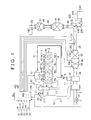
- FIG. 1 shows an internal combustion engine to which the exhaust emission control system according to the present embodiment is applied and its surrounding mechanism.
- the internal combustion engine 1 according to the present embodiment is a diesel engine.
- the internal combustion engine 1 includes a plurality of cylinders #1 to #4.
- a plurality of fuel injection valves 4a to 4d are provided at a cylinder head 2. These fuel injection valves 4a to 4d inject fuel into combustion chambers of the respective cylinders #1 to #4.
- the cylinder head 2 has intake ports and exhaust ports 6a to 6d in correspondence with the respective cylinders #1 to #4. The intake ports are respectively used to introduce fresh air into the cylinders #1 to #4.
- the exhaust ports 6a to 6d are used to emit combustion gas to the outside of the cylinders.
- the fuel injection valves 4a to 4d are connected to a common rail 9 that accumulates high-pressure fuel.
- the common rail 9 is connected to a supply pump 10.
- the supply pump 10 draws fuel in a fuel tank, and supplies high-pressure fuel to the common rail 9.
- High-pressure fuel supplied to the common rail 9 is injected from each of the fuel injection valves 4a to 4d into the corresponding cylinder at the time when each of the fuel injection valves 4a to 4d opens.
- An intake manifold 7 is connected to the intake ports.
- the intake manifold 7 is connected to an intake passage 3.
- An intake air throttle valve 16 is provided in the intake passage 3. The intake air throttle valve 16 is used to adjust an intake air flow rate.
- An exhaust manifold 8 is connected to the exhaust ports 6a to 6d.
- the exhaust manifold 8 is connected to the exhaust passage 26.
- a turbocharger 11 is provided in the exhaust passage 26.
- the turbocharger 11 supercharges intake air that is introduced into the cylinders by utilizing exhaust pressure.
- An intercooler 18 is provided in the intake passage 3 between an intake-side compressor of the turbocharger 11 and the intake air throttle valve 16. The intercooler 18 cools intake air of which the temperature is raised through supercharging of the turbocharger 11.
- a first purification member 30 that purifies exhaust gas is provided downstream of an exhaust-side turbine of the turbocharger 11 in the exhaust gas flow direction in the exhaust passage 26.
- An oxidation catalyst 31 and a filter 32 are arranged inside the first purification member 30 in series in a direction in which exhaust gas flows.
- a catalyst is supported on the oxidation catalyst 31.
- the catalyst oxidizes hydrocarbons (HC) in exhaust gas.
- the filter 32 is a member that traps particulate matter (PM) in exhaust gas.
- the filter 32 is formed of porous ceramics.
- a catalyst is supported on the filter 32. The catalyst is used to facilitate oxidation of PM. PM in exhaust gas is trapped at the time when exhaust gas passes through the porous wall of the filter 32.
- a fuel addition valve 5 is provided near a collecting portion of the exhaust manifold 8.
- the fuel addition valve 5 is used to supply fuel to the oxidation catalyst 31 or the filter 32 as an additive.
- the fuel addition valve 5 is connected to the supply pump 10 via a fuel supply tube 27.
- the arrangement location of the fuel addition valve 5 may be changed as needed as long as the location is in an exhaust system upstream of the first purification member 30.
- a second purification member 40 that purifies exhaust gas is provided downstream of the first purification member 30 in the exhaust gas flow direction in the exhaust passage 26.
- a selective reduction NOx catalyst (hereinafter, referred to as SCR catalyst) 41 is arranged inside the second purification member 40.
- the SCR catalyst 41 reduces and purifies NOx in exhaust gas by utilizing reducing agent.
- a third purification member 50 that purifies exhaust gas is provided downstream of the second purification member 40 in the exhaust gas flow direction in the exhaust passage 26.
- An ammonia oxidation catalyst 51 is arranged inside the third purification member 50. The ammonia oxidation catalyst 51 purifies ammonia in exhaust gas.
- the internal combustion engine 1 includes an urea aqueous solution supply mechanism 200.
- the urea aqueous solution supply mechanism 200 supplies urea aqueous solution, which serves as reducing agent, to the SCR catalyst 41.
- the urea aqueous solution supply mechanism 200 includes a tank 210, an urea aqueous solution addition valve 230, an urea aqueous solution supply tube 240 and a pump 220.
- the tank 210 stores urea aqueous solution.
- the urea aqueous solution addition valve 230 injects and supplies urea aqueous solution into the exhaust passage 26.
- the urea aqueous solution supply tube 240 connects the urea aqueous solution addition valve 230 to the tank 210.
- the urea aqueous solution supply tube 240 is made of a metal.
- the pump 220 is provided in the urea aqueous solution supply tube 240.
- the urea aqueous solution addition valve 230 is made of a metal.
- a component, such as a coil, for opening the injection hole of the addition valve 230 is accommodated inside the urea aqueous solution addition valve 230.
- the urea aqueous solution addition valve 230 is provided in the exhaust passage 26 between the first purification member 30 and the second purification member 40.
- the injection hole of the urea aqueous solution addition valve 230 is directed toward the SCR catalyst 41.
- the pump 220 is an electric pump. When the pump 220 rotates in the forward direction, the pump 220 feeds urea aqueous solution from the tank 210 to the urea aqueous solution addition valve 230. In contrast, when the pump 220 rotates in the reverse direction, the pump 220 feeds urea aqueous solution from the urea aqueous solution addition valve 230 to the tank 210. That is, when the pump 220 rotates in the reverse direction, urea aqueous solution is recovered from the urea aqueous solution addition valve 230 and the urea aqueous solution supply tube 240, and is returned to the tank 210.
- a dispersion plate 60 is provided in the exhaust passage 26 between the urea aqueous solution addition valve 230 and the SCR catalyst 41.
- the dispersion plate 60 facilitates atomization of urea aqueous solution by dispersing the urea aqueous solution injected from the urea aqueous solution addition valve 230.
- Urea aqueous solution injected from the urea aqueous solution addition valve 230 changes into ammonia by the hydrolysis of urea due to the heat of exhaust gas. Then, the ammonia is supplied to the SCR catalyst 41 as the reducing agent for NOx. Ammonia supplied to the SCR catalyst 41 is adsorbed by the SCR catalyst 41, and is utilized to reduce NOx. Part of hydrolyzed ammonia is directly utilized to reduce NOx before being adsorbed by the SCR catalyst 41.
- the internal combustion engine 1 includes an exhaust gas recirculation device (hereinafter, referred to as EGR device).
- the EGR device is a device that decreases a combustion temperature in the cylinders by introducing part of exhaust gas into intake air and, as a result, reduces the amount of NOx generated.
- the EGR device is formed of an EGR passage 13, an EGR valve 15, an EGR cooler 14, and the like.
- the EGR passage 13 provides fluid communication between the intake passage 3 and the exhaust manifold 8.
- the EGR valve 15 is provided in the EGR passage 13.
- An exhaust gas recirculation amount that is introduced from the exhaust passage 26 to the intake passage 3 is regulated by adjusting the opening degree of the EGR valve 15. That is, an EGR amount is regulated by adjusting the opening degree of the EGR valve 15.
- the temperature of exhaust gas flowing through the EGR passage 13 is decreased by the EGR cooler 14.
- an air flow meter 19 detects an intake air flow rate GA in the intake passage 3.
- a throttle valve opening degree sensor 20 detects the opening degree of the intake air throttle valve 16.
- An engine rotation speed sensor 21 detects the rotation speed of a crankshaft. That is, the engine rotation speed sensor 21 detects an engine rotation speed NE.
- An accelerator sensor 22 detects the depression amount of an accelerator pedal. That is, the accelerator sensor 22 detects an accelerator operation amount ACCP.
- An outside air temperature sensor 23 detects an outside air temperature THout.
- a vehicle speed sensor 24 detects a vehicle speed SPD of a vehicle on which the internal combustion engine 1 is mounted.
- An ignition switch 25 detects start operation and stop operation of the internal combustion engine 1, conducted by a driver of the vehicle.
- a first exhaust gas temperature sensor 100 detects a first exhaust gas temperature TH1.
- the first exhaust gas temperature sensor 100 is provided upstream of the oxidation catalyst 31 in the exhaust gas flow direction.
- the first exhaust gas temperature TH1 is the temperature of exhaust gas before the exhaust gas flows into the oxidation catalyst 31.
- a differential pressure sensor 110 detects a pressure difference ⁇ P in exhaust gas pressure.
- the pressure difference ⁇ P is a pressure difference between an exhaust gas pressure upstream of the filter 32 in the exhaust gas flow direction and an exhaust gas pressure downstream of the filter 32 in the exhaust gas flow direction.
- a second exhaust gas temperature sensor 120 and a first NOx sensor 130 are provided upstream of the urea aqueous solution addition valve 230 in the exhaust gas flow direction in the exhaust passage 26 between the first purification member 30 and the second purification member 40.
- the second exhaust gas temperature sensor 120 detects a second exhaust gas temperature TH2.
- the second exhaust gas temperature TH2 is the temperature of exhaust gas before the exhaust gas flows into the SCR catalyst 41.
- the first NOx sensor 130 detects a first NOx concentration N1.
- the first NOx concentration N1 is a NOx concentration in exhaust gas before the exhaust gas flows into the SCR catalyst 41.
- a second NOx sensor 140 is provided in the exhaust passage 26 downstream of the third purification member 50 in the exhaust gas flow direction.
- the second NOx sensor 140 detects a second NOx concentration N2.
- the second NOx concentration N2 is the NOx concentration of exhaust gas purified by the SCR catalyst 41.
- the control device 80 is mainly formed of a microcomputer that includes a central processing unit (CPU) 80a, a read only memory (ROM), a random access memory (RAM), a counter 80b, an input interface, an output interface, and the like.
- the read only memory prestores various programs, maps, and the like.
- the random access memory temporarily stores computation results of the CPU, and the like. Electric power is supplied from a battery to each of the CPU 80a, the counter 80b and the above-described various sensors.
- the various controls include fuel injection amount control/fuel injection timing control over the fuel injection valves 4a to 4d and the fuel addition valve 5, discharge pressure control over the supply pump 10, drive amount control over an actuator 17, opening degree control over the EGR valve 15, and the like.
- the actuator 17 opens or closes the intake air throttle valve 16.
- control device 80 estimates the amount of PM trapped by the filter 32 on the basis of the pressure difference ⁇ P that is detected by the differential pressure sensor 110. Then, the control device 80 executes filter regeneration process for regenerating the filter 32 when it is determined that the estimated trapped amount of PM exceeds a preset threshold.
- filter regeneration process fuel is injected from the fuel addition valve 5 into the exhaust manifold 8. Fuel injected from the fuel addition valve 5 is burned as it reaches the oxidation catalyst 31. Thus, the exhaust gas temperature is raised. Exhaust gas raised in temperature by the oxidation catalyst 31 flows into the filter 32, so the temperature of the filter 32 is raised. Thus, PM deposited in the filter 32 is oxidized, and the filter 32 is regenerated.
- the control device 80 executes control for adding urea aqueous solution with the use of the urea aqueous solution addition valve 230 as one of the exhaust gas purification controls.
- an urea additive amount just enough to reduce NOx that is emitted from the internal combustion engine 1 is calculated on the basis of the engine operating state, and the like.
- the valve opening state of the urea aqueous solution addition valve 230 is controlled such that the urea aqueous solution of the calculated urea additive amount is injected from the urea aqueous solution addition valve 230 to the exhaust passage 26.
- NOx in exhaust gas is reduced and purified.
- Urea aqueous solution addition control is executed on the condition that an addition flag that indicates permission or prohibition of addition of urea aqueous solution is set to an "ON" state that indicates permission of addition of urea aqueous solution during operation of the internal combustion engine 1.
- urea aqueous solution injected from the urea aqueous solution addition valve 230 changes into ammonia by the hydrolysis of urea, and reduces and purifies NOx in exhaust gas.
- part of urea in the injected urea aqueous solution may become a crystal, a mixture, or the like, that originates from urea without being hydrolyzed into ammonia, and may be deposited near the injection hole of the urea aqueous solution addition valve 230, the dispersion plate 60 or the SCR catalyst 41 to form a deposit.
- Such a deposit is removed through not only the above-described filter regeneration process but also being burned during operation in which the temperature of exhaust gas is high, such as during high-load operation of the internal combustion engine 1.
- urea aqueous solution in the urea aqueous solution addition valve 230 may boil because the urea aqueous solution addition valve 230 is exposed to high-temperature exhaust gas.
- the metal material of the urea aqueous solution addition valve 230 may corrode.
- recovery control when the temperature of exhaust gas is higher than or equal to a reference temperature, recovery control is executed to recover urea aqueous solution in the urea aqueous solution addition valve 230 through the urea aqueous solution supply tube 240 by rotating the pump 220 in the reverse direction. This suppresses boiling of urea aqueous solution in the urea aqueous solution addition valve 230.
- Recovery control in the present embodiment includes control for recovering urea aqueous solution from the urea aqueous solution supply tube 240 by rotating the pump 220 in the reverse direction as described above and control for keeping the state after recovering urea aqueous solution from the urea aqueous solution supply tube 240.
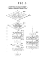
- the control device 80 executes urea aqueous solution recovery and addition control in accordance with the procedure of processes shown in the flowchart of FIG. 2 .
- a series of processes shown in FIG. 2 are executed as interrupt process at predetermined intervals during engine operation.
- the second exhaust gas temperature TH2 is detected in step S10.
- the second exhaust gas temperature TH2 is the temperature of exhaust gas immediately before the exhaust gas flows into the SCR catalyst 41.
- the control device 80 detects the second exhaust gas temperature TH2 on the basis of a signal that is input from the second exhaust gas temperature sensor 120.
- step S11 it is determined whether the second exhaust gas temperature TH2 is higher than or equal to the reference temperature.
- the reference temperature is set to a temperature, at which it is allowed to estimate that urea aqueous solution does not boil in the urea aqueous solution addition valve 230 on the basis of the fact that the second exhaust gas temperature TH2 is lower than the reference temperature.
- urea aqueous solution may boil when urea aqueous solution remains in the urea aqueous solution addition valve 230. Therefore, the process proceeds to step S12.
- step S12 it is determined whether recovery of urea aqueous solution has been completed. That is, it is determined whether recovery of urea aqueous solution has been already completed after the second exhaust gas temperature TH2 becomes higher than or equal to the reference temperature. This determination may be made by determining whether a count value C of the counter 80b is larger than or equal to a counter determination value ⁇ .
- the count value C indicates a period during which recovery of urea aqueous solution is carried out.
- the counter determination value ⁇ is set to an integer larger than or equal to "1".
- the counter determination value ⁇ is set to a value at which it is allowed to estimate that urea aqueous solution in an amount corresponding to urea aqueous solution in the urea aqueous solution addition valve 230 has been recovered through the urea aqueous solution supply tube 240 on the basis of the fact that the count value C is larger than or equal to the counter determination value ⁇ .
- step S12 when it is determined in step S12 that recovery of urea aqueous solution has been completed (YES in step S12), the control device 80 once ends the process. This keeps a state where urea aqueous solution has been recovered from the urea aqueous solution addition valve 230.
- an addition flag is set to an "OFF" state. For example, when the second exhaust gas temperature TH2 is higher than or equal to the reference temperature in the last process, the addition flag has been already set to the "OFF" state, so, in this case, the addition flag is kept in the "OFF” state.
- the control device 80 stops urea aqueous solution addition control. That is, addition of urea aqueous solution from the urea aqueous solution addition valve 230 is stopped, and urea aqueous solution addition control is stopped.
- Urea aqueous solution addition control is to purify NOx in exhaust gas as described above.
- step S14 a recovery flag is set to an "ON" state.
- the recovery flag is for the control device 80 to execute recovery of urea aqueous solution on the basis of the recovery flag set to the "ON” state.
- the control device 80 executes recovery of urea aqueous solution on the basis of the recovery flag set to the "ON” state. Specifically, the control device 80 recovers urea aqueous solution from the urea aqueous solution addition valve 230 and the urea aqueous solution supply tube 240 and returns the urea solution to the tank 210 by rotating the pump 220 in the reverse direction.
- the recovery of urea aqueous solution is carried out continuously during a period in which the recovery flag is set to the "ON" state. For example, when the second exhaust gas temperature TH2 is larger than or equal to the reference temperature in the last process as well, the recovery flag has been already set to the "ON” state, so, in such a case, the recovery flag is kept in the "ON" state.
- step S15 in order to measure a recovery period of urea aqueous solution, the count value C of the counter 80b is calculated. Specifically, the current count value C is calculated by adding "1" to the last count value C.
- step S16 it is determined whether the count value C is larger than or equal to the counter determination value ⁇ .
- the control device 80 once ends the process. That is, the process ends while the recovery flag is kept in the "ON" state.
- step S16 when it is determined in step S16 that the count value C is larger than or equal to the counter determination value ⁇ (YES in step S16), the process proceeds to step S17.
- step S17 the recovery flag is set to the "OFF" state, and the control device 80 once ends the process. That is, when affirmative determination is made in step S16, urea aqueous solution in the urea aqueous solution addition valve 230 is recovered, so it is possible to suppress boiling of urea aqueous solution in the urea aqueous solution addition valve 230. Therefore, recovery of urea aqueous solution is stopped by stopping the pump 220.
- step S11 When it is determined in step S11 in the process shown in FIG. 2 that the second exhaust gas temperature TH2 is not higher than or equal to the reference temperature (NO in step S11), the process proceeds to step S18.
- step S18 the count value C of the counter 80b is reset to "0". When the count value C is already “0”, the value is kept.
- step S19 the recovery flag is set to the "OFF” state. In step S19, when the recovery flag is already set to the "OFF” state, the recovery flag is kept in the "OFF” state.
- step S18 and step S19 even when the second exhaust gas temperature TH2 is higher than or equal to the reference temperature in the last process, but when the second exhaust gas temperature TH2 becomes lower than the reference temperature, measurement of a recovery period is stopped and reset, and urea aqueous solution recovery control is stopped.
- step S20 an additive amount for purifying NOx is set. That is, as described above, an urea additive amount just enough to reduce NOx that is emitted from the internal combustion engine 1 is calculated on the basis of the engine operating state, and the like.
- step S21 the addition flag is set to the "ON” state.
- step S21 when the addition flag has been already set to the "ON” state, the addition flag is kept in the "ON” state as it is. In this way, when the second exhaust gas temperature TH2 is lower than the reference temperature, the addition flag is set to the "ON” state, so addition of urea aqueous solution from the urea aqueous solution addition valve 230 is carried out. Then, the control device 80 once ends the process.
- the exhaust emission control system according to the present embodiment includes the urea aqueous solution addition valve 230 that supplies urea aqueous solution to the exhaust passage 26.
- the exhaust emission control system executes recovery control for recovering urea aqueous solution in the urea aqueous solution addition valve 230.
- urea aqueous solution easily boils in the urea aqueous solution addition valve 230
- urea aqueous solution in the urea aqueous solution addition valve 230 is recovered. Therefore, it is possible to suppress boiling of urea aqueous solution in the urea aqueous solution addition valve 230.
- urea aqueous solution recovery control when the estimated temperature of exhaust gas is higher than or equal to the reference temperature, urea aqueous solution recovery control is executed. That is, when the engine operating state is a state where it is estimated that the temperature of exhaust gas is higher than or equal to the reference temperature, the control device 80 estimates that the temperature of exhaust gas is higher than or equal to the reference temperature and executes urea aqueous solution recovery control.
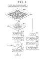
- control device 80 executes urea aqueous solution recovery and addition control in accordance with the procedure of processes shown in the flowchart of FIG. 3 .
- a series of processes shown in FIG. 3 are executed as interrupt process at predetermined intervals during engine operation.
- step S30 it is initially determined in step S30 whether the engine operating state is a state where the temperature of exhaust gas is higher than or equal to the reference temperature.
- the temperature of exhaust gas is high when the internal combustion engine 1 is operating in a high load state (high-load operating state) or when temperature raising control for raising the temperature of exhaust gas, such as filter regeneration process, is being executed. Therefore, it is possible to estimate that the temperature of exhaust gas is higher than or equal to the reference temperature.
- the engine operating state where the temperature of exhaust gas is higher than or equal to the reference temperature is a state where the internal combustion engine 1 is operated at a high load or a state where temperature raising control for raising the temperature of exhaust gas, such as filter regeneration process, is being executed.
- step S30 when the internal combustion engine 1 is in a high-load operating state or when temperature raising control, such as filter regeneration process, is being executed, it is determined that the engine operating state is the state where the temperature of exhaust gas is higher than or equal to the reference temperature.
- the control device 80 determines whether the internal combustion engine 1 is in a high-load operating state by acquiring the load of the internal combustion engine on the basis of the intake air flow rate GA detected.
- control device 80 determines whether filter regeneration process is being executed on the basis of whether a fuel addition command is output to the fuel addition valve 5.
- the fuel addition command is output to the fuel addition valve 5 in order to execute filter regeneration process.
- the control device 80 determines whether the engine operating state is the state where the temperature of exhaust gas is higher than or equal to the reference temperature on the basis of these determinations.
- step S30 When affirmative determination is made in step S30 (YES in step S30), the process from step S12 is executed, and urea aqueous solution in the urea aqueous solution addition valve 230 is recovered. On the other hand, when negative determination is made in step S30 (NO in step S30), the process from step S18 is executed, and urea aqueous solution is added in order to purify and reduce NOx.
- urea aqueous solution recovery control is executed in an engine operating state where the temperature of exhaust gas is higher than or equal to the reference temperature.
- recovery control is executed without directly detecting the temperature of exhaust gas when the temperature of exhaust gas is higher than or equal to the reference temperature.
- urea aqueous solution recovery control is executed in the engine operating state where the temperature of exhaust gas is higher than or equal to the reference temperature.
- the temperature of exhaust gas varies on the basis of the engine operating state. Therefore, a rise in the temperature of exhaust gas to the reference temperature or above may be determined not on the basis of the temperature of exhaust gas itself but on the basis of the engine operating state.
- recovery control in the engine operating state where the temperature of exhaust gas is higher than or equal to the reference temperature, it is possible to execute recovery control without directly detecting the temperature of exhaust gas when the temperature of exhaust gas is higher than or equal to the reference temperature.
- the process of regenerating the filter 32 is started when it is determined that the amount of PM trapped by the filter 32 exceeds a preset threshold.
- the filter 32 traps PM in the exhaust passage 26. Therefore, when the degree of deviation between the amount of PM trapped by the filter 32 and the threshold for starting regeneration process falls within a predetermined range, filter regeneration process is highly likely to be started within a predetermined period.
- urea aqueous solution recovery control is executed to recover urea aqueous solution from the urea aqueous solution addition valve 230.
- the reference amount is lower than the threshold for starting the process of regenerating the filter 32.
- the reference amount is, for example, set to an amount that is smaller than the trapped amount of PM, which is the threshold for starting the process of regenerating the filter 32, and an amount at which it is estimated that filter regeneration process starts within the predetermined period on the basis of the degree of deviation between the threshold and the reference amount.
- the predetermined period for setting the reference amount is, for example, set to a period during which the pump 220 is driven in order to recover the entire amount of urea aqueous solution in the urea aqueous solution addition valve 230.
- control device 80 executes urea aqueous solution recovery and addition control in accordance with the procedure of processes shown in the flowchart of FIG. 4 .
- a series of processes shown in FIG. 4 are executed as interrupt process at predetermined intervals during engine operation.
- step S35 it is initially determined in step S35 whether the estimated PM trapped amount of the filter 32 is larger than or equal to the reference amount or whether the filter 32 is being regenerated.
- the control device 80 calculates the trapped amount of PM trapped by the filter 32 on the basis of the pressure difference ⁇ P.
- the pressure difference ⁇ P is detected by the differential pressure sensor 110. Then, when it is determined that the calculated trapped amount of PM is larger than or equal to the reference amount, affirmative determination is made in step S35 (YES in step S35). Then, the process proceeds to step S12.
- step S12 the process after step S12 is executed, and urea aqueous solution recovery control is executed to recover urea aqueous solution in the urea aqueous solution addition valve 230.
- the predetermined period for setting the reference amount is set as described above, so it is possible to complete recovery of urea aqueous solution in the urea aqueous solution addition valve 230 before execution of filter regeneration process is started.
- step S35 when negative determination is made in step S35 (NO in step S35), the process after step S18 is executed, and urea aqueous solution is added in order to purify and reduce NOx.
- urea aqueous solution is added in order to purify and reduce NOx.
- urea aqueous solution recovery control when the amount of PM trapped by the filter 32 is larger than or equal to the reference amount, urea aqueous solution recovery control is executed.
- the reference amount is smaller than the threshold for starting filter regeneration process.
- urea aqueous solution recovery control is started.
- the predetermined period is set in the above-described mode, so recovery of urea aqueous solution in the urea aqueous solution addition valve 230 is completed before the temperature of exhaust gas becomes higher than or equal to the reference temperature through execution of filter regeneration process.
- urea aqueous solution recovery control when it is predicted that the engine operating state changes into the state where the temperature of exhaust gas is higher than or equal to the reference temperature, urea aqueous solution recovery control is executed.
- the control device 80 executes urea aqueous solution recovery and addition control in accordance with the procedure of processes shown in the flowchart of FIG. 5 .
- a series of processes shown in FIG. 5 are executed as interrupt process at predetermined intervals during engine operation.
- step S40 it is initially determined in step S40 whether the engine operating state is the state where the temperature of exhaust gas is higher than or equal to the reference temperature or whether it is predicted that the engine operating state changes into that state.
- the control device 80 calculates the trapped amount of PM trapped by the filter 32 on the basis of the pressure difference ⁇ P that is detected by the differential pressure sensor 110.
- step S40 when the calculated trapped amount of PM becomes larger than or equal to the reference amount, it is predicted that the engine operating state changes into the state where the temperature of exhaust gas is higher than or equal to the reference temperature, and affirmative determination is made (YES in step S40).
- the process of regenerating the filter 32 when the process of regenerating the filter 32 is being executed, it is determined that the engine operating state is the state where the temperature of exhaust gas is higher than or equal to the reference temperature, and affirmative determination is made (YES in step S40).
- the process after step S12 is executed, and urea aqueous solution in the urea aqueous solution addition valve 230 is recovered.
- step S40 when negative determination is made in step S40 (NO in step S40), the process after step S18 is executed, and urea aqueous solution is added in order to purify and reduce NOx.
- urea aqueous solution is added in order to purify and reduce NOx.
- urea aqueous solution recovery control when it is predicted that the engine operating state changes into the state where the temperature of exhaust gas is higher than or equal to the reference temperature, urea aqueous solution recovery control is executed in advance of the change.
- urea aqueous solution recovery control is started in advance of the situation that the temperature of exhaust gas is higher than or equal to the reference temperature.
- the predetermined period is set in the above-described mode, so recovery of urea aqueous solution in the urea aqueous solution addition valve 230 is completed before the temperature of exhaust gas becomes higher than or equal to the reference temperature.
- the temperature of exhaust gas becomes higher than or equal to a predetermined temperature that is higher than the reference temperature during urea aqueous solution recovery control
- recovery control is stopped, and urea aqueous solution is injected from the urea aqueous solution addition valve 230.
- components, such as a coil, that constitute the urea aqueous solution addition valve 230 may undergo heat damage when the temperature of exhaust gas is higher than the predetermined temperature.
- the predetermined temperature is set to a temperature, at which it is estimated that heat damage to the components that constitute the urea aqueous solution addition valve 230 does not occur, when the temperature of exhaust gas is lower than or equal to the predetermined temperature.
- control device 80 executes urea aqueous solution recovery and addition control in accordance with the procedure of processes shown in the flowchart of FIG. 6 .
- a series of processes shown in FIG. 6 are executed as interrupt process at predetermined intervals during engine operation.
- the second exhaust gas temperature TH2 is detected in step S50.
- the control device 80 detects the second exhaust gas temperature TH2 on the basis of a signal that is input from the second exhaust gas temperature sensor 120.
- step S51 it is determined whether the second exhaust gas temperature TH2 is higher than or equal to the reference temperature.
- step S51 it is determined whether the second exhaust gas temperature TH2 is higher than or equal to the reference temperature.
- urea aqueous solution in the urea aqueous solution addition valve 230 may boil. Therefore, the process proceeds to step S52.
- step S52 it is determined whether the second exhaust gas temperature TH2 is higher than or equal to the predetermined temperature that is higher than the reference temperature.
- the second exhaust gas temperature TH2 is lower than the predetermined temperature (NO in step S52)
- step S53 it is determined whether recovery of urea aqueous solution has been completed.
- the control device 80 once ends the process.
- step S53 when it is determined in step S53 that recovery of urea aqueous solution has not been completed (NO in step S53), the process proceeds to step S54, and the addition flag is set to the "OFF" state.
- the addition flag When the addition flag has been already set to the "OFF” state, the addition flag is kept as it is.
- the control device 80 stops opening the urea aqueous solution addition valve 230, and stops adding urea aqueous solution into the exhaust passage 26.
- the process proceeds to step S55, and the recovery flag is set to the "ON" state.
- the recovery flag is kept as it is.
- the control device 80 recovers urea aqueous solution. Specifically, the control device 80 recovers urea aqueous solution from the urea aqueous solution addition valve 230 and the urea aqueous solution supply tube 240 and returns the urea solution to the tank 210 by rotating the pump 220 in the reverse direction. The recovery of urea aqueous solution is carried out continuously during a period in which the urea aqueous solution recovery flag is set to the "ON" state.
- step S56 the count value is calculated.
- step S57 it is determined whether the count value C is larger than or equal to the counter determination value ⁇ .
- step S58 the control device 80 once ends the process.
- step S58 the recovery flag is set to the "OFF" state, and the control device 80 once ends the process.
- the control device 80 stops the pump 220 and stops recovering urea aqueous solution.
- step S52 when it is determined in step S52 in the process shown in FIG. 6 that the second exhaust gas temperature TH2 is higher than or equal to the predetermined temperature (YES in step S52), the process proceeds to step S59. In step S59, the count value is set to "0". Then, the process proceeds to step S60. In step S60, the recovery flag is set to the "OFF" state. Thus, when urea aqueous solution is being recovered or recovery has been completed in the last process, the count value is reset to "0", and urea aqueous solution recovery control is stopped.
- step S61 the injection amount of urea aqueous solution is set on the basis of the second exhaust gas temperature TH2 detected in step S50.
- the injection amount of urea aqueous solution is an injection amount per unit time, which is required in order to cool the urea aqueous solution addition valve 230. That is, the injection amount set here differs from the above-described additive amount of urea aqueous solution that is supplied in order to reduce and purify NOx.
- the injection amount set here is set to an amount at which it is possible to suppress heat damage to the urea aqueous solution addition valve 230 by cooling the addition valve 230 through injection of urea aqueous solution in the injection amount at the detected second exhaust gas temperature TH2.
- step S62 the addition flag is set to the "ON" state.
- the control device 80 controls the valve open state of the urea aqueous solution addition valve 230 such that urea aqueous solution in the amount set in step S62 is injected from the urea aqueous solution addition valve 230.
- step S62 the control device 80 once ends the process.
- step S52 when it is determined in step S52 that the second exhaust gas temperature TH2 is higher than or equal to the predetermined temperature, urea aqueous solution is injected from the urea aqueous solution addition valve 230 in order to cool the urea aqueous solution addition valve 230.
- urea aqueous solution recovery control is stopped even during recovery control, and urea aqueous solution is injected.
- urea aqueous solution recovery control is executed.
- step S51 When it is determined in step S51 in the process shown in FIG. 6 that the second exhaust gas temperature TH2 is not higher than or equal to the reference temperature (NO in step S51), the process proceeds to step S63, and the count value C is reset to "0". Thus, the process proceeds to step S64. In step S64, the recovery flag is set to the "OFF" state. Subsequently, the process proceeds to step S65. In step S65, the additive amount of urea aqueous solution for purifying NOx is calculated. Then, in step S66, the addition flag is set to the "ON" state. In this way, when it is determined that the second exhaust gas temperature TH2 is not higher than or equal to the reference temperature, urea aqueous solution is added to purify and reduce NOx.
- the injection amount of urea aqueous solution for cooling the urea aqueous solution addition valve is set on the basis of the second exhaust gas temperature TH2.
- the injection amount of urea aqueous solution may be a constant amount irrespective of the second exhaust gas temperature TH2.
- the injection amount of urea aqueous solution may be set to the same amount as the additive amount of urea aqueous solution for purifying NOx.
- urea aqueous solution recovery control, urea aqueous solution injection control and urea aqueous solution addition control are switched on the basis of the second exhaust gas temperature TH2 detected.
- Urea aqueous solution injection control is control for cooling the urea aqueous solution addition valve.
- Urea aqueous solution addition control is control for adding urea aqueous solution to purify and reduce NOx.
- these controls may be switched on the basis of the engine operating state.
- step S70 it is determined in step S70 whether the engine operating state is the state where the temperature of exhaust gas is higher than or equal to the reference temperature.
- step S70 negative determination is made in step S70 (NO in step S70)
- urea aqueous solution is added for purifying and reducing NOx in the process from step S63.
- step S71 it is determined whether the engine operating state is the state where the temperature of exhaust gas is higher than or equal to the predetermined temperature that is higher than the reference temperature.
- step S71 negative determination is made in step S71 (NO in step S71).
- urea aqueous solution recovery control is executed in the process from step S53.
- affirmative determination is made in step S71 (YES in step S71).
- urea aqueous solution injection control for cooling the urea aqueous solution addition valve 230 is executed in the process from step S59.
- step S70 it may be determined whether the engine operating state is the state where the temperature of exhaust gas is higher than or equal to the reference temperature or whether it is predicted that the engine operating state changes into that state.
- the engine operating state where the temperature of exhaust gas is higher than or equal to the reference temperature is established when temperature raising control, such as filter regeneration process, is being executed or when the high-load operation state is carried out.
- temperature raising control such as filter regeneration process
- urea aqueous solution recovery control may be executed when the temperature raising control is executed.
- urea aqueous solution recovery control is started in advance of the situation that the temperature of exhaust gas is higher than or equal to the reference temperature, and recovery of urea aqueous solution is completed before the temperature of exhaust gas becomes higher than or equal to the reference temperature.
- urea aqueous solution recovery control is started in advance of the situation that the temperature of exhaust gas is higher than or equal to the reference temperature and, after the temperature of exhaust gas becomes higher than or equal to the reference temperature, recovery of urea aqueous solution is completed.
- urea aqueous solution recovery control may be executed as it is predicted that the temperature of exhaust gas becomes higher than or equal to the reference temperature when the deposition amount of the deposit is larger than or equal to a predetermined amount smaller than the threshold as well.
- the high-load operation state is carried out, for example, when the accelerator operation amount ACCP steeply increases. Therefore, urea aqueous solution recovery control may be executed by predicting that the temperature of exhaust gas becomes higher than or equal to the reference temperature.
- urea aqueous solution in the amount corresponding to the amount of urea aqueous solution in the urea aqueous solution addition valve is recovered.
- the recovery amount of urea aqueous solution is not limited to the above-described embodiment. That is, for example, even when the temperature of exhaust gas is higher than or equal to the reference temperature but is not so high, it may be possible to suppress boiling of urea aqueous solution in the urea aqueous solution addition valve by recovering urea aqueous solution from only the distal end portion of the urea aqueous solution addition valve.
- urea aqueous solution may boil also in the urea aqueous solution supply tube and the supply tube may undergo metallic corrosion. Therefore, it may be desirable to also recover part of urea aqueous solution in the urea aqueous solution supply tube.
- the recovery amount of urea aqueous solution may be increased. It is possible to adjust the recovery amount of urea aqueous solution by appropriately adjusting a period during which the pump is driven or the rotation speed of the pump.
- the temperature of exhaust gas is higher than or equal to the reference temperature without setting the recovery amount of urea aqueous solution
- recovery of urea aqueous solution in the urea aqueous solution supply tube may be continued. That is, in this case, when the state where the temperature of exhaust gas is higher than or equal to the reference temperature continues for a long period, the entire amount of urea aqueous solution in the urea aqueous solution addition valve and the urea aqueous solution supply tube is recovered.
- whether the second exhaust gas temperature TH2 is higher than or equal to the reference temperature is determined by the control device on the basis of the detection signal of the second exhaust gas temperature sensor. Instead, whether the second exhaust gas temperature TH2 is higher than or equal to the reference temperature may be determined on the basis of, for example, the calculated temperature of exhaust gas that is estimated each time on the basis of the engine operating state.
- urea aqueous solution when urea aqueous solution is recovered from the urea aqueous solution supply tube, the pump is rotated in the reverse direction.
- recovery may be carried out in a mode other than this mode.
- urea aqueous solution may be recovered by providing a selector valve, or the like, which changes the flow direction of urea aqueous solution in the middle of the urea aqueous solution supply tube.
- urea aqueous solution is used as the reducing agent.
- another reducing agent may be used.
Abstract
Description
- The invention relates to an exhaust emission control system for an internal combustion engine, and a control method for the exhaust emission control system.
- For example, as is described in Japanese Patent Application Publication No.
2008-274952 JP 2008-274952 A - Incidentally, for example, when the temperature of exhaust gas is low, urea in the urea aqueous solution injected from the addition valve forms a deposit, such as a crystal and a mixture, originating from urea without being hydrolyzed into ammonia, and is deposited in the NOx purification catalyst, or the like. Therefore, the NOx purification efficiency of the NOx purification catalyst decreases. In the exhaust emission control system described in
JP 2008-274952 A - Incidentally, temperature raising control for raising the temperature of exhaust gas includes not only control for removing a deposit that originates from urea in
JP 2008-274952 A - The invention provides an exhaust emission control system for an internal combustion engine, which is able to suppress metallic corrosion of an addition valve due to boiling of reducing agent in the addition valve, and a control method for the exhaust emission control system.
- A first aspect of the invention provides an exhaust emission control system for an internal combustion engine. The exhaust emission control system includes: an addition valve that supplies reducing agent to an exhaust passage and a supply tube that supplies the reducing agent to the addition valve, wherein, when a temperature of exhaust gas flowing through the exhaust passage is higher than or equal to a reference temperature, recovery control for recovering the reducing agent in the supply tube is executed.
- With the above configuration, when the temperature of exhaust gas is higher than or equal to the reference temperature and the reducing agent easily boils in the addition valve, the reducing agent in the supply tube is recovered. Therefore, it is possible to recover the reducing agent in the addition valve through the supply tube. Thus, it is possible to suppress boiling of the reducing agent in the addition valve. Thus, it is possible to suppress metallic corrosion of the addition valve due to boiling of the reducing agent in the addition valve.
- In the exhaust emission control system according to the first aspect of the invention, the recovery control may be executed when the temperature of exhaust gas, which is acquired through any one of actual measurement and estimation, is higher than or equal to the reference temperature.
- With the above configuration, the actually detected temperature of exhaust gas or the temperature of exhaust gas estimated from the engine operating state, or the like, is compared with the reference temperature, so it is possible to determine whether the temperature of exhaust gas is higher than or equal to the reference temperature. Then, it is possible to execute recovery control when the temperature of exhaust gas is higher than or equal to the reference temperature.
- In the exhaust emission control system according to the first aspect of the invention, the recovery control may be executed in an engine operating state where the temperature of exhaust gas is higher than or equal to the reference temperature.
- The temperature of exhaust gas varies on the basis of the engine operating state. Therefore, whether the temperature of exhaust gas rises to the reference temperature or above may be determined not on the basis of the temperature of exhaust gas itself but on the basis of the engine operating state. Then, in the above configuration, the recovery control is configured to be executed in the engine operating state where it is estimated that the temperature of exhaust gas is higher than or equal to the reference temperature. With this configuration as well, it is possible to execute the recovery control when the temperature of exhaust gas is higher than or equal to the reference temperature.
- In the exhaust emission control system according to the first embodiment of the invention, a filter that traps particulate matter in exhaust gas may be provided in the exhaust passage, regeneration process for regenerating the filter may be executed by raising the temperature of exhaust gas when an amount of the particulate matter trapped by the filter becomes larger than or equal to a threshold, and the recovery control may be executed when the amount of the particulate matter trapped by the filter is larger than or equal to a reference amount that is smaller than the threshold.
- With the above configuration, when the particulate matter trapped by the filter is larger than or equal to the reference amount, urea aqueous solution recovery control is executed, so the urea aqueous solution recovery control is executed in advance of a situation that the amount of particulate matter trapped by the filter becomes larger than or equal to the threshold and then temperature raising control for regenerating the filter is executed. Thus, it is possible to start the recovery control in advance of the situation that the temperature of exhaust gas is higher than or equal to the reference temperature.
- In the exhaust emission control system according to the first aspect of the invention, the recovery control may be executed when it is predicted that an engine operating state changes into a state where the temperature of exhaust gas is higher than or equal to the reference temperature.
- As described above, the temperature of exhaust gas varies on the basis of the engine operating state. Then, it is possible to predict to some extent whether the engine operating state changes into the state where the temperature of exhaust gas rises to the reference temperature or above. Then, in the above configuration, when it is predicted that the engine operating state changes into the state where the temperature of exhaust gas is higher than or equal to the reference temperature, the recovery control is executed in advance of the change. With the above configuration, it is possible to start the recovery control in advance of the situation that the temperature of exhaust gas is higher than or equal to the reference temperature.
- In the exhaust emission control system according to the first aspect, the engine operating state where the temperature of exhaust gas is higher than or equal to the reference temperature may be established when temperature raising control for raising the temperature of exhaust gas is executed.
- In the exhaust emission control system according to the first aspect, the engine operating state where the temperature of exhaust gas is higher than or equal to the reference temperature may be established when the internal combustion engine is operating at high load.
- The temperature raising control may be, for example, control for raising the temperature of exhaust gas in order to eliminate soot, deposit, or the like, deposited in an exhaust system.
- In the exhaust emission control system according to the first aspect of the invention, when the temperature of exhaust gas is higher than or equal to a predetermined temperature that is higher than the reference temperature while the recovery control is being executed, the recovery control is stopped, and the reducing agent is injected from the addition valve.
- In the above configuration, when the temperature of exhaust gas is higher than the predetermined temperature that is higher than the reference temperature and the addition valve may undergo heat damage during recovery control, the reducing agent is injected from the addition valve. When the reducing agent is injected, relatively low-temperature reducing agent is supplied from, for example, a tank, or the like, to the addition valve, so the addition valve is cooled. Thus, it is possible to suppress heat damage to the addition valve.
- A second aspect of the invention provides a control method for an exhaust emission control system for an internal combustion engine. The exhaust emission control system includes: an addition valve that supplies reducing agent to an exhaust passage and a supply tube that supplies the reducing agent to the addition valve. The control method includes: when a temperature of exhaust gas flowing through the exhaust passage is higher than or equal to a reference temperature, executing recovery control for recovering the reducing agent in the supply tube.
- Features, advantages, and technical and industrial significance of exemplary embodiments of the invention will be described below with reference to the accompanying drawings, in which like numerals denote like elements, and wherein:
-
FIG. 1 is a schematic view that shows an internal combustion engine and its surrounding configuration to which an exhaust emission control system for an internal combustion engine according to an embodiment of the invention is applied; -
FIG. 2 is a flowchart that shows the procedure of executing urea aqueous solution recovery and addition control according to the embodiment; -
FIG. 3 is a flowchart that shows the procedure of executing urea aqueous solution recovery and addition control in the exhaust emission control system for an internal combustion engine according to the embodiment of the invention; -
FIG. 4 is a flowchart that shows the procedure of executing urea aqueous solution recovery and addition control in the exhaust emission control system for an internal combustion engine according to the embodiment of the invention; -
FIG. 5 is a flowchart that shows the procedure of executing urea aqueous solution recovery and addition control in the exhaust emission control system for an internal combustion engine according to the embodiment of the invention; -
FIG. 6 is a flowchart that shows the procedure of executing urea aqueous solution recovery and addition control in the exhaust emission control system for an internal combustion engine according to the embodiment of the invention; and -
FIG. 7 is a flowchart that shows the procedure of executing urea aqueous solution recovery and addition control in the exhaust emission control system for an internal combustion engine according to the embodiment of the invention. - Hereinafter, one example embodiment of the exhaust emission control system for an internal combustion engine according to the invention will be described with reference to
FIG. 1 andFIG. 2 .FIG. 1 shows an internal combustion engine to which the exhaust emission control system according to the present embodiment is applied and its surrounding mechanism. As shown inFIG. 1 , theinternal combustion engine 1 according to the present embodiment is a diesel engine. - As shown in
FIG. 1 , theinternal combustion engine 1 includes a plurality ofcylinders # 1 to #4. A plurality offuel injection valves 4a to 4d are provided at acylinder head 2. Thesefuel injection valves 4a to 4d inject fuel into combustion chambers of therespective cylinders # 1 to #4. Thecylinder head 2 has intake ports andexhaust ports 6a to 6d in correspondence with therespective cylinders # 1 to #4. The intake ports are respectively used to introduce fresh air into thecylinders # 1 to #4. Theexhaust ports 6a to 6d are used to emit combustion gas to the outside of the cylinders. - The
fuel injection valves 4a to 4d are connected to acommon rail 9 that accumulates high-pressure fuel. Thecommon rail 9 is connected to asupply pump 10. Thesupply pump 10 draws fuel in a fuel tank, and supplies high-pressure fuel to thecommon rail 9. High-pressure fuel supplied to thecommon rail 9 is injected from each of thefuel injection valves 4a to 4d into the corresponding cylinder at the time when each of thefuel injection valves 4a to 4d opens. - An
intake manifold 7 is connected to the intake ports. Theintake manifold 7 is connected to anintake passage 3. An intakeair throttle valve 16 is provided in theintake passage 3. The intakeair throttle valve 16 is used to adjust an intake air flow rate. - An
exhaust manifold 8 is connected to theexhaust ports 6a to 6d. Theexhaust manifold 8 is connected to theexhaust passage 26. Aturbocharger 11 is provided in theexhaust passage 26. Theturbocharger 11 supercharges intake air that is introduced into the cylinders by utilizing exhaust pressure. Anintercooler 18 is provided in theintake passage 3 between an intake-side compressor of theturbocharger 11 and the intakeair throttle valve 16. Theintercooler 18 cools intake air of which the temperature is raised through supercharging of theturbocharger 11. - A
first purification member 30 that purifies exhaust gas is provided downstream of an exhaust-side turbine of theturbocharger 11 in the exhaust gas flow direction in theexhaust passage 26. Anoxidation catalyst 31 and afilter 32 are arranged inside thefirst purification member 30 in series in a direction in which exhaust gas flows. - A catalyst is supported on the
oxidation catalyst 31. The catalyst oxidizes hydrocarbons (HC) in exhaust gas. Thefilter 32 is a member that traps particulate matter (PM) in exhaust gas. Thefilter 32 is formed of porous ceramics. A catalyst is supported on thefilter 32. The catalyst is used to facilitate oxidation of PM. PM in exhaust gas is trapped at the time when exhaust gas passes through the porous wall of thefilter 32. - A
fuel addition valve 5 is provided near a collecting portion of theexhaust manifold 8. Thefuel addition valve 5 is used to supply fuel to theoxidation catalyst 31 or thefilter 32 as an additive. Thefuel addition valve 5 is connected to thesupply pump 10 via afuel supply tube 27. The arrangement location of thefuel addition valve 5 may be changed as needed as long as the location is in an exhaust system upstream of thefirst purification member 30. - A
second purification member 40 that purifies exhaust gas is provided downstream of thefirst purification member 30 in the exhaust gas flow direction in theexhaust passage 26. A selective reduction NOx catalyst (hereinafter, referred to as SCR catalyst) 41 is arranged inside thesecond purification member 40. TheSCR catalyst 41 reduces and purifies NOx in exhaust gas by utilizing reducing agent. - Furthermore, a
third purification member 50 that purifies exhaust gas is provided downstream of thesecond purification member 40 in the exhaust gas flow direction in theexhaust passage 26. Anammonia oxidation catalyst 51 is arranged inside thethird purification member 50. Theammonia oxidation catalyst 51 purifies ammonia in exhaust gas. - The
internal combustion engine 1 includes an urea aqueoussolution supply mechanism 200. The urea aqueoussolution supply mechanism 200 supplies urea aqueous solution, which serves as reducing agent, to theSCR catalyst 41. The urea aqueoussolution supply mechanism 200 includes a tank 210, an urea aqueoussolution addition valve 230, an urea aqueoussolution supply tube 240 and apump 220. The tank 210 stores urea aqueous solution. The urea aqueoussolution addition valve 230 injects and supplies urea aqueous solution into theexhaust passage 26. The urea aqueoussolution supply tube 240 connects the urea aqueoussolution addition valve 230 to the tank 210. The urea aqueoussolution supply tube 240 is made of a metal. Thepump 220 is provided in the urea aqueoussolution supply tube 240. - The urea aqueous
solution addition valve 230 is made of a metal. A component, such as a coil, for opening the injection hole of theaddition valve 230 is accommodated inside the urea aqueoussolution addition valve 230. The urea aqueoussolution addition valve 230 is provided in theexhaust passage 26 between thefirst purification member 30 and thesecond purification member 40. The injection hole of the urea aqueoussolution addition valve 230 is directed toward theSCR catalyst 41. When the urea aqueoussolution addition valve 230 is opened through energization of the coil, urea aqueous solution is injected and supplied into theexhaust passage 26 via the urea aqueoussolution addition valve 230. - The
pump 220 is an electric pump. When thepump 220 rotates in the forward direction, thepump 220 feeds urea aqueous solution from the tank 210 to the urea aqueoussolution addition valve 230. In contrast, when thepump 220 rotates in the reverse direction, thepump 220 feeds urea aqueous solution from the urea aqueoussolution addition valve 230 to the tank 210. That is, when thepump 220 rotates in the reverse direction, urea aqueous solution is recovered from the urea aqueoussolution addition valve 230 and the urea aqueoussolution supply tube 240, and is returned to the tank 210. - A
dispersion plate 60 is provided in theexhaust passage 26 between the urea aqueoussolution addition valve 230 and theSCR catalyst 41. Thedispersion plate 60 facilitates atomization of urea aqueous solution by dispersing the urea aqueous solution injected from the urea aqueoussolution addition valve 230. - Urea aqueous solution injected from the urea aqueous
solution addition valve 230 changes into ammonia by the hydrolysis of urea due to the heat of exhaust gas. Then, the ammonia is supplied to theSCR catalyst 41 as the reducing agent for NOx. Ammonia supplied to theSCR catalyst 41 is adsorbed by theSCR catalyst 41, and is utilized to reduce NOx. Part of hydrolyzed ammonia is directly utilized to reduce NOx before being adsorbed by theSCR catalyst 41. - Other than the above, the
internal combustion engine 1 includes an exhaust gas recirculation device (hereinafter, referred to as EGR device). The EGR device is a device that decreases a combustion temperature in the cylinders by introducing part of exhaust gas into intake air and, as a result, reduces the amount of NOx generated. The EGR device is formed of anEGR passage 13, anEGR valve 15, anEGR cooler 14, and the like. TheEGR passage 13 provides fluid communication between theintake passage 3 and theexhaust manifold 8. TheEGR valve 15 is provided in theEGR passage 13. An exhaust gas recirculation amount that is introduced from theexhaust passage 26 to theintake passage 3 is regulated by adjusting the opening degree of theEGR valve 15. That is, an EGR amount is regulated by adjusting the opening degree of theEGR valve 15. The temperature of exhaust gas flowing through theEGR passage 13 is decreased by theEGR cooler 14. - Various sensors for detecting an engine operating state are attached to the
internal combustion engine 1. For example, anair flow meter 19 detects an intake air flow rate GA in theintake passage 3. A throttle valveopening degree sensor 20 detects the opening degree of the intakeair throttle valve 16. An enginerotation speed sensor 21 detects the rotation speed of a crankshaft. That is, the enginerotation speed sensor 21 detects an engine rotation speed NE. An accelerator sensor 22 detects the depression amount of an accelerator pedal. That is, the accelerator sensor 22 detects an accelerator operation amount ACCP. An outside air temperature sensor 23 detects an outside air temperature THout. Avehicle speed sensor 24 detects a vehicle speed SPD of a vehicle on which theinternal combustion engine 1 is mounted. Anignition switch 25 detects start operation and stop operation of theinternal combustion engine 1, conducted by a driver of the vehicle. - A first exhaust
gas temperature sensor 100 detects a first exhaust gas temperature TH1. The first exhaustgas temperature sensor 100 is provided upstream of theoxidation catalyst 31 in the exhaust gas flow direction. The first exhaust gas temperature TH1 is the temperature of exhaust gas before the exhaust gas flows into theoxidation catalyst 31. Adifferential pressure sensor 110 detects a pressure difference ΔP in exhaust gas pressure. The pressure difference ΔP is a pressure difference between an exhaust gas pressure upstream of thefilter 32 in the exhaust gas flow direction and an exhaust gas pressure downstream of thefilter 32 in the exhaust gas flow direction. - A second exhaust
gas temperature sensor 120 and afirst NOx sensor 130 are provided upstream of the urea aqueoussolution addition valve 230 in the exhaust gas flow direction in theexhaust passage 26 between thefirst purification member 30 and thesecond purification member 40. The second exhaustgas temperature sensor 120 detects a second exhaust gas temperature TH2. The second exhaust gas temperature TH2 is the temperature of exhaust gas before the exhaust gas flows into theSCR catalyst 41. Thefirst NOx sensor 130 detects a first NOx concentration N1. The first NOx concentration N1 is a NOx concentration in exhaust gas before the exhaust gas flows into theSCR catalyst 41. - A
second NOx sensor 140 is provided in theexhaust passage 26 downstream of thethird purification member 50 in the exhaust gas flow direction. Thesecond NOx sensor 140 detects a second NOx concentration N2. The second NOx concentration N2 is the NOx concentration of exhaust gas purified by theSCR catalyst 41. - Outputs of these various sensors, and the like, are input to a
control device 80. Thecontrol device 80 is mainly formed of a microcomputer that includes a central processing unit (CPU) 80a, a read only memory (ROM), a random access memory (RAM), acounter 80b, an input interface, an output interface, and the like. The read only memory prestores various programs, maps, and the like. The random access memory temporarily stores computation results of the CPU, and the like. Electric power is supplied from a battery to each of theCPU 80a, thecounter 80b and the above-described various sensors. - Various controls over the
internal combustion engine 1 are executed by thecontrol device 80. The various controls, for example, include fuel injection amount control/fuel injection timing control over thefuel injection valves 4a to 4d and thefuel addition valve 5, discharge pressure control over thesupply pump 10, drive amount control over anactuator 17, opening degree control over theEGR valve 15, and the like. Theactuator 17 opens or closes the intakeair throttle valve 16. - Furthermore, the
control device 80 estimates the amount of PM trapped by thefilter 32 on the basis of the pressure difference ΔP that is detected by thedifferential pressure sensor 110. Then, thecontrol device 80 executes filter regeneration process for regenerating thefilter 32 when it is determined that the estimated trapped amount of PM exceeds a preset threshold. In this filter regeneration process, fuel is injected from thefuel addition valve 5 into theexhaust manifold 8. Fuel injected from thefuel addition valve 5 is burned as it reaches theoxidation catalyst 31. Thus, the exhaust gas temperature is raised. Exhaust gas raised in temperature by theoxidation catalyst 31 flows into thefilter 32, so the temperature of thefilter 32 is raised. Thus, PM deposited in thefilter 32 is oxidized, and thefilter 32 is regenerated. - The
control device 80 executes control for adding urea aqueous solution with the use of the urea aqueoussolution addition valve 230 as one of the exhaust gas purification controls. In the addition control, an urea additive amount just enough to reduce NOx that is emitted from theinternal combustion engine 1 is calculated on the basis of the engine operating state, and the like. In the addition control, the valve opening state of the urea aqueoussolution addition valve 230 is controlled such that the urea aqueous solution of the calculated urea additive amount is injected from the urea aqueoussolution addition valve 230 to theexhaust passage 26. Thus, NOx in exhaust gas is reduced and purified. Urea aqueous solution addition control is executed on the condition that an addition flag that indicates permission or prohibition of addition of urea aqueous solution is set to an "ON" state that indicates permission of addition of urea aqueous solution during operation of theinternal combustion engine 1. - Here, as described above, urea aqueous solution injected from the urea aqueous
solution addition valve 230 changes into ammonia by the hydrolysis of urea, and reduces and purifies NOx in exhaust gas. However, for example, when the temperature of exhaust gas is low, part of urea in the injected urea aqueous solution may become a crystal, a mixture, or the like, that originates from urea without being hydrolyzed into ammonia, and may be deposited near the injection hole of the urea aqueoussolution addition valve 230, thedispersion plate 60 or theSCR catalyst 41 to form a deposit. Such a deposit is removed through not only the above-described filter regeneration process but also being burned during operation in which the temperature of exhaust gas is high, such as during high-load operation of theinternal combustion engine 1. - Incidentally, during operation in which the temperature of exhaust gas is high in this way, urea aqueous solution in the urea aqueous
solution addition valve 230 may boil because the urea aqueoussolution addition valve 230 is exposed to high-temperature exhaust gas. In this way, when urea aqueous solution boils in the urea aqueoussolution addition valve 230, the metal material of the urea aqueoussolution addition valve 230 may corrode. Then, in the present embodiment, when the temperature of exhaust gas is higher than or equal to a reference temperature, recovery control is executed to recover urea aqueous solution in the urea aqueoussolution addition valve 230 through the urea aqueoussolution supply tube 240 by rotating thepump 220 in the reverse direction. This suppresses boiling of urea aqueous solution in the urea aqueoussolution addition valve 230. Recovery control in the present embodiment includes control for recovering urea aqueous solution from the urea aqueoussolution supply tube 240 by rotating thepump 220 in the reverse direction as described above and control for keeping the state after recovering urea aqueous solution from the urea aqueoussolution supply tube 240. - Hereinafter, recovery control for recovering urea aqueous solution from the urea aqueous
solution supply tube 240 will be described with reference toFIG. 2 . Thecontrol device 80 executes urea aqueous solution recovery and addition control in accordance with the procedure of processes shown in the flowchart ofFIG. 2 . A series of processes shown inFIG. 2 are executed as interrupt process at predetermined intervals during engine operation. - As shown in
FIG. 2 , when urea aqueous solution recovery and addition control is started, the second exhaust gas temperature TH2 is detected in step S10. The second exhaust gas temperature TH2 is the temperature of exhaust gas immediately before the exhaust gas flows into theSCR catalyst 41. Thecontrol device 80 detects the second exhaust gas temperature TH2 on the basis of a signal that is input from the second exhaustgas temperature sensor 120. - Subsequently, the process proceeds to step S11. In step S11, it is determined whether the second exhaust gas temperature TH2 is higher than or equal to the reference temperature. Here, the reference temperature is set to a temperature, at which it is allowed to estimate that urea aqueous solution does not boil in the urea aqueous
solution addition valve 230 on the basis of the fact that the second exhaust gas temperature TH2 is lower than the reference temperature. When it is determined in step S11 that the second exhaust gas temperature TH2 is higher than or equal to the reference temperature (YES in step S11), urea aqueous solution may boil when urea aqueous solution remains in the urea aqueoussolution addition valve 230. Therefore, the process proceeds to step S12. - In step S12, it is determined whether recovery of urea aqueous solution has been completed. That is, it is determined whether recovery of urea aqueous solution has been already completed after the second exhaust gas temperature TH2 becomes higher than or equal to the reference temperature. This determination may be made by determining whether a count value C of the
counter 80b is larger than or equal to a counter determination value α. The count value C indicates a period during which recovery of urea aqueous solution is carried out. In addition, the counter determination value α is set to an integer larger than or equal to "1". The counter determination value α is set to a value at which it is allowed to estimate that urea aqueous solution in an amount corresponding to urea aqueous solution in the urea aqueoussolution addition valve 230 has been recovered through the urea aqueoussolution supply tube 240 on the basis of the fact that the count value C is larger than or equal to the counter determination value α. When it is determined in step S12 that recovery of urea aqueous solution has not been completed on the basis of the fact that the count value C is smaller than the counter determination value α (NO in step S12), the process proceeds to step S13. On the other hand, when it is determined in step S12 that recovery of urea aqueous solution has been completed (YES in step S12), thecontrol device 80 once ends the process. This keeps a state where urea aqueous solution has been recovered from the urea aqueoussolution addition valve 230. - In step S13, an addition flag is set to an "OFF" state. For example, when the second exhaust gas temperature TH2 is higher than or equal to the reference temperature in the last process, the addition flag has been already set to the "OFF" state, so, in this case, the addition flag is kept in the "OFF" state. Thus, the
control device 80 stops urea aqueous solution addition control. That is, addition of urea aqueous solution from the urea aqueoussolution addition valve 230 is stopped, and urea aqueous solution addition control is stopped. Urea aqueous solution addition control is to purify NOx in exhaust gas as described above. - Subsequently, the process proceeds to step S14. In step S14, a recovery flag is set to an "ON" state. The recovery flag is for the
control device 80 to execute recovery of urea aqueous solution on the basis of the recovery flag set to the "ON" state. Thecontrol device 80 executes recovery of urea aqueous solution on the basis of the recovery flag set to the "ON" state. Specifically, thecontrol device 80 recovers urea aqueous solution from the urea aqueoussolution addition valve 230 and the urea aqueoussolution supply tube 240 and returns the urea solution to the tank 210 by rotating thepump 220 in the reverse direction. The recovery of urea aqueous solution is carried out continuously during a period in which the recovery flag is set to the "ON" state. For example, when the second exhaust gas temperature TH2 is larger than or equal to the reference temperature in the last process as well, the recovery flag has been already set to the "ON" state, so, in such a case, the recovery flag is kept in the "ON" state. - Subsequently, the process proceeds to step S15. In step S15, in order to measure a recovery period of urea aqueous solution, the count value C of the
counter 80b is calculated. Specifically, the current count value C is calculated by adding "1" to the last count value C. - Subsequently, the process proceeds to step S16. In step S16, it is determined whether the count value C is larger than or equal to the counter determination value α. When it is determined in step S16 that the count value C is smaller than the counter determination value α (NO in step S16), it is estimated that urea aqueous solution still remains in the urea aqueous
solution addition valve 230 and urea aqueous solution may boil in the urea aqueoussolution addition valve 230. Therefore, thecontrol device 80 once ends the process. That is, the process ends while the recovery flag is kept in the "ON" state. - On the other hand, when it is determined in step S16 that the count value C is larger than or equal to the counter determination value α (YES in step S16), the process proceeds to step S17. In step S17, the recovery flag is set to the "OFF" state, and the
control device 80 once ends the process. That is, when affirmative determination is made in step S16, urea aqueous solution in the urea aqueoussolution addition valve 230 is recovered, so it is possible to suppress boiling of urea aqueous solution in the urea aqueoussolution addition valve 230. Therefore, recovery of urea aqueous solution is stopped by stopping thepump 220. In this way, recovery of urea aqueous solution is stopped when urea aqueous solution in the urea aqueoussolution addition valve 230 has been recovered, so it is possible to keep urea aqueous solution remaining in the urea aqueoussolution supply tube 240. Therefore, at the time of the next addition control, it is possible to promptly start urea aqueous solution addition control by promptly supplying urea aqueous solution to the urea aqueoussolution addition valve 230. - When it is determined in step S11 in the process shown in
FIG. 2 that the second exhaust gas temperature TH2 is not higher than or equal to the reference temperature (NO in step S11), the process proceeds to step S18. In step S18, the count value C of thecounter 80b is reset to "0". When the count value C is already "0", the value is kept. In step S19, the recovery flag is set to the "OFF" state. In step S19, when the recovery flag is already set to the "OFF" state, the recovery flag is kept in the "OFF" state. That is, through the processes of step S18 and step S19, even when the second exhaust gas temperature TH2 is higher than or equal to the reference temperature in the last process, but when the second exhaust gas temperature TH2 becomes lower than the reference temperature, measurement of a recovery period is stopped and reset, and urea aqueous solution recovery control is stopped. - Subsequently, the process proceeds to step S20, and an additive amount for purifying NOx is set. That is, as described above, an urea additive amount just enough to reduce NOx that is emitted from the
internal combustion engine 1 is calculated on the basis of the engine operating state, and the like. In step S21, the addition flag is set to the "ON" state. In step S21, when the addition flag has been already set to the "ON" state, the addition flag is kept in the "ON" state as it is. In this way, when the second exhaust gas temperature TH2 is lower than the reference temperature, the addition flag is set to the "ON" state, so addition of urea aqueous solution from the urea aqueoussolution addition valve 230 is carried out. Then, thecontrol device 80 once ends the process. - Next, the operation of the exhaust emission control system according to the present embodiment will be described. The exhaust emission control system according to the present embodiment includes the urea aqueous
solution addition valve 230 that supplies urea aqueous solution to theexhaust passage 26. When the temperature of exhaust gas flowing through theexhaust passage 26 is higher than or equal to the reference temperature, the exhaust emission control system executes recovery control for recovering urea aqueous solution in the urea aqueoussolution addition valve 230. Thus, when urea aqueous solution easily boils in the urea aqueoussolution addition valve 230, urea aqueous solution in the urea aqueoussolution addition valve 230 is recovered. Therefore, it is possible to suppress boiling of urea aqueous solution in the urea aqueoussolution addition valve 230. - According to the above-described present embodiment, the operation and advantageous effect at the following (1) are obtained.
- (1) The exhaust emission control system for the
internal combustion engine 1 according to the present embodiment includes the urea aqueoussolution addition valve 230 that supplies urea aqueous solution to theexhaust passage 26 and the urea aqueoussolution supply tube 240 that supplies urea aqueous solution to theaddition valve 230. When the temperature of exhaust gas flowing through theexhaust passage 26 is higher than or equal to the reference temperature, the exhaust emission control system executes recovery control for recovering urea aqueous solution in the urea aqueoussolution supply tube 240. Thus, when urea aqueous solution easily boils in the urea aqueoussolution addition valve 230, urea aqueous solution in the urea aqueoussolution addition valve 230 is recovered through the urea aqueoussolution supply tube 240. Therefore, it is possible to suppress boiling of urea aqueous solution in the urea aqueoussolution addition valve 230. Thus, it is possible to suppress metallic corrosion of the urea aqueoussolution addition valve 230 due to boiling of urea aqueous solution in the urea aqueoussolution addition valve 230. - Next, one embodiment of the invention will be described with reference to
FIG. 3 . In the present embodiment, the difference from the above-described embodiment will be mainly described. The other components and operation are the same as those of the above-described embodiment unless otherwise specified. In addition, like reference numerals denote the same components as those of the above-described embodiment. - In the present embodiment, when the estimated temperature of exhaust gas is higher than or equal to the reference temperature, urea aqueous solution recovery control is executed. That is, when the engine operating state is a state where it is estimated that the temperature of exhaust gas is higher than or equal to the reference temperature, the
control device 80 estimates that the temperature of exhaust gas is higher than or equal to the reference temperature and executes urea aqueous solution recovery control. - Specifically, in the present embodiment, the
control device 80 executes urea aqueous solution recovery and addition control in accordance with the procedure of processes shown in the flowchart ofFIG. 3 . A series of processes shown inFIG. 3 are executed as interrupt process at predetermined intervals during engine operation. - When urea aqueous solution recovery and addition control shown in
FIG. 3 is started, it is initially determined in step S30 whether the engine operating state is a state where the temperature of exhaust gas is higher than or equal to the reference temperature. Here, the temperature of exhaust gas is high when theinternal combustion engine 1 is operating in a high load state (high-load operating state) or when temperature raising control for raising the temperature of exhaust gas, such as filter regeneration process, is being executed. Therefore, it is possible to estimate that the temperature of exhaust gas is higher than or equal to the reference temperature. That is, the engine operating state where the temperature of exhaust gas is higher than or equal to the reference temperature is a state where theinternal combustion engine 1 is operated at a high load or a state where temperature raising control for raising the temperature of exhaust gas, such as filter regeneration process, is being executed. Thus, in step S30, when theinternal combustion engine 1 is in a high-load operating state or when temperature raising control, such as filter regeneration process, is being executed, it is determined that the engine operating state is the state where the temperature of exhaust gas is higher than or equal to the reference temperature. Specifically, thecontrol device 80 determines whether theinternal combustion engine 1 is in a high-load operating state by acquiring the load of the internal combustion engine on the basis of the intake air flow rate GA detected. In addition, thecontrol device 80 determines whether filter regeneration process is being executed on the basis of whether a fuel addition command is output to thefuel addition valve 5. The fuel addition command is output to thefuel addition valve 5 in order to execute filter regeneration process. Then, thecontrol device 80 determines whether the engine operating state is the state where the temperature of exhaust gas is higher than or equal to the reference temperature on the basis of these determinations. - When affirmative determination is made in step S30 (YES in step S30), the process from step S12 is executed, and urea aqueous solution in the urea aqueous
solution addition valve 230 is recovered. On the other hand, when negative determination is made in step S30 (NO in step S30), the process from step S18 is executed, and urea aqueous solution is added in order to purify and reduce NOx. - Next, the operation of the exhaust emission control system according to the present embodiment will be described. In the exhaust emission control system according to the present embodiment, urea aqueous solution recovery control is executed in an engine operating state where the temperature of exhaust gas is higher than or equal to the reference temperature. Thus, by executing recovery control in the engine operating state where the temperature of exhaust gas is higher than or equal to the reference temperature, recovery control is executed without directly detecting the temperature of exhaust gas when the temperature of exhaust gas is higher than or equal to the reference temperature.
- According to the above-described present embodiment, similar operation and advantageous effect to (1) of the above-described embodiment and the operation and advantageous effect of the following (2) are obtained. (2) In the exhaust emission control system according to the present embodiment, urea aqueous solution recovery control is executed in the engine operating state where the temperature of exhaust gas is higher than or equal to the reference temperature. The temperature of exhaust gas varies on the basis of the engine operating state. Therefore, a rise in the temperature of exhaust gas to the reference temperature or above may be determined not on the basis of the temperature of exhaust gas itself but on the basis of the engine operating state. Thus, by executing recovery control in the engine operating state where the temperature of exhaust gas is higher than or equal to the reference temperature, it is possible to execute recovery control without directly detecting the temperature of exhaust gas when the temperature of exhaust gas is higher than or equal to the reference temperature.
- Note that the expression "when a temperature of exhaust gas is higher than or equal to a reference temperature" herein and the accompanying claims means a case that the temperature of exhaust gas is expected to be higher than or equal to the reference temperature or another case that the temperature of exhaust gas is higher than or equal to a reference temperature.
- Next, one embodiment of the invention will be described with reference to
FIG. 4 . In the present embodiment, the difference from the above-described embodiment will be mainly described. The other components and operation are the same as those of the above-described embodiment unless otherwise specified. In addition, like reference numerals denote the same components as those of the above-described embodiment. - As described above, the process of regenerating the
filter 32 is started when it is determined that the amount of PM trapped by thefilter 32 exceeds a preset threshold. Thefilter 32 traps PM in theexhaust passage 26. Therefore, when the degree of deviation between the amount of PM trapped by thefilter 32 and the threshold for starting regeneration process falls within a predetermined range, filter regeneration process is highly likely to be started within a predetermined period. Then, in the present embodiment, for example, when the estimated amount of PM trapped by thefilter 32 is larger than or equal to a reference amount, urea aqueous solution recovery control is executed to recover urea aqueous solution from the urea aqueoussolution addition valve 230. The reference amount is lower than the threshold for starting the process of regenerating thefilter 32. The reference amount is, for example, set to an amount that is smaller than the trapped amount of PM, which is the threshold for starting the process of regenerating thefilter 32, and an amount at which it is estimated that filter regeneration process starts within the predetermined period on the basis of the degree of deviation between the threshold and the reference amount. Furthermore, the predetermined period for setting the reference amount is, for example, set to a period during which thepump 220 is driven in order to recover the entire amount of urea aqueous solution in the urea aqueoussolution addition valve 230. - In the present embodiment, the
control device 80 executes urea aqueous solution recovery and addition control in accordance with the procedure of processes shown in the flowchart ofFIG. 4 . A series of processes shown inFIG. 4 are executed as interrupt process at predetermined intervals during engine operation. - When urea aqueous solution recovery and addition control shown in
FIG. 4 is started, it is initially determined in step S35 whether the estimated PM trapped amount of thefilter 32 is larger than or equal to the reference amount or whether thefilter 32 is being regenerated. Thecontrol device 80 calculates the trapped amount of PM trapped by thefilter 32 on the basis of the pressure difference ΔP. The pressure difference ΔP is detected by thedifferential pressure sensor 110. Then, when it is determined that the calculated trapped amount of PM is larger than or equal to the reference amount, affirmative determination is made in step S35 (YES in step S35). Then, the process proceeds to step S12. In addition, when thecontrol device 80 is outputting the fuel addition command to thefuel addition valve 5 and it is determined that thefilter 32 is being regenerated, the process proceeds to step S12. Thus, the process after step S12 is executed, and urea aqueous solution recovery control is executed to recover urea aqueous solution in the urea aqueoussolution addition valve 230. Thus, in advance of execution of filter regeneration process, it is possible to recover urea aqueous solution in the urea aqueoussolution addition valve 230. In addition, the predetermined period for setting the reference amount is set as described above, so it is possible to complete recovery of urea aqueous solution in the urea aqueoussolution addition valve 230 before execution of filter regeneration process is started. During filter regeneration process, the state where thepump 220 is stopped and urea aqueous solution in the urea aqueoussolution addition valve 230 has been recovered is kept. - On the other hand, when negative determination is made in step S35 (NO in step S35), the process after step S18 is executed, and urea aqueous solution is added in order to purify and reduce NOx. Next, the operation of the exhaust emission control system according to the present embodiment will be described.
- In the exhaust emission control system according to the present embodiment, when the amount of PM trapped by the
filter 32 is larger than or equal to the reference amount, urea aqueous solution recovery control is executed. The reference amount is smaller than the threshold for starting filter regeneration process. Thus, in advance of the situation that the temperature of exhaust gas is higher than or equal to the reference temperature through execution of filter regeneration process, urea aqueous solution recovery control is started. Then, the predetermined period is set in the above-described mode, so recovery of urea aqueous solution in the urea aqueoussolution addition valve 230 is completed before the temperature of exhaust gas becomes higher than or equal to the reference temperature through execution of filter regeneration process. - According to the above-described embodiment, operation and advantageous effects similar to the above-described (1) and (2) and the operation and advantageous effect of the following (3) are obtained. (3) In the exhaust emission control system according to the present embodiment, when the amount of PM trapped by the
filter 32 is larger than or equal to the reference amount that is smaller than the threshold for starting filter regeneration process, urea aqueous solution recovery control is executed. Thus, in advance of the situation that the temperature of exhaust gas is higher than or equal to the reference temperature through execution of filter regeneration process, it is possible to start urea aqueous solution recovery control. Therefore, it is possible to suppress boiling of urea aqueous solution in the urea aqueoussolution addition valve 230. Thus, it is possible to suppress metallic corrosion of the urea aqueoussolution addition valve 230. - Next, one embodiment of the invention will be described with reference to
FIG. 5 . In the present embodiment, the difference from the above-described embodiment will be mainly described. The other components and operation are the same as those of the above-described embodiment unless otherwise specified. In addition, like reference numerals denote the same components as those of the above-described embodiment. - In the present embodiment, when it is predicted that the engine operating state changes into the state where the temperature of exhaust gas is higher than or equal to the reference temperature, urea aqueous solution recovery control is executed. In the present embodiment, the
control device 80 executes urea aqueous solution recovery and addition control in accordance with the procedure of processes shown in the flowchart ofFIG. 5 . A series of processes shown inFIG. 5 are executed as interrupt process at predetermined intervals during engine operation. - When urea aqueous solution recovery and addition control shown in
FIG. 5 is started, it is initially determined in step S40 whether the engine operating state is the state where the temperature of exhaust gas is higher than or equal to the reference temperature or whether it is predicted that the engine operating state changes into that state. Specifically, as described in the above embodiment, when the amount of PM trapped by thefilter 32 becomes larger than or equal to the reference amount, filter regeneration process is executed within the predetermined period. Therefore, it is predicted that the engine operating state changes into the state where the temperature of exhaust gas is higher than or equal to the reference temperature. Then, thecontrol device 80 calculates the trapped amount of PM trapped by thefilter 32 on the basis of the pressure difference ΔP that is detected by thedifferential pressure sensor 110. Then, in step S40, when the calculated trapped amount of PM becomes larger than or equal to the reference amount, it is predicted that the engine operating state changes into the state where the temperature of exhaust gas is higher than or equal to the reference temperature, and affirmative determination is made (YES in step S40). In addition, for example, when the process of regenerating thefilter 32 is being executed, it is determined that the engine operating state is the state where the temperature of exhaust gas is higher than or equal to the reference temperature, and affirmative determination is made (YES in step S40). Thus, the process after step S12 is executed, and urea aqueous solution in the urea aqueoussolution addition valve 230 is recovered. Therefore, in advance of the situation that the temperature of exhaust gas is higher than or equal to the reference temperature, it is possible to start recovering urea aqueous solution in the urea aqueoussolution addition valve 230. In addition, by setting the reference amount similarly to the above-described embodiment, it is possible to complete recovery of urea aqueous solution in the urea aqueoussolution addition valve 230 before the temperature of exhaust gas becomes higher than or equal to the reference temperature. Then, when the temperature of exhaust gas is higher than or equal to the reference temperature, the state where thepump 220 is stopped and urea aqueous solution in the urea aqueoussolution addition valve 230 has been recovered is kept. - On the other hand, when negative determination is made in step S40 (NO in step S40), the process after step S18 is executed, and urea aqueous solution is added in order to purify and reduce NOx. Next, the operation of the exhaust emission control system according to the present embodiment will be described.
- In the exhaust emission control system according to the present embodiment, when it is predicted that the engine operating state changes into the state where the temperature of exhaust gas is higher than or equal to the reference temperature, urea aqueous solution recovery control is executed in advance of the change. Thus, urea aqueous solution recovery control is started in advance of the situation that the temperature of exhaust gas is higher than or equal to the reference temperature. Then, the predetermined period is set in the above-described mode, so recovery of urea aqueous solution in the urea aqueous
solution addition valve 230 is completed before the temperature of exhaust gas becomes higher than or equal to the reference temperature. - According to the above-described embodiment, operation and advantageous effects similar to the above-described (1) and (2) and the operation and advantageous effect of the following (4) are obtained. (4) In the exhaust emission control system according to the present embodiment, when it is predicted that the engine operating state changes into the state where the temperature of exhaust gas is higher than or equal to the reference temperature, urea aqueous solution recovery control is executed in advance of the change. Thus, it is possible to start urea aqueous solution recovery control in advance of the situation that the temperature of exhaust gas is higher than or equal to the reference temperature. Therefore, it is possible to suppress boiling of urea aqueous solution in the urea aqueous
solution addition valve 230. Thus, it is possible to suppress metallic corrosion of the urea aqueoussolution addition valve 230. - Next, one embodiment of the invention will be described with reference to
FIG. 6 . In the present embodiment, the difference from the above-described embodiment will be mainly described. The other components and operation are the same as those of the above-described embodiment unless otherwise specified. In addition, like reference numerals denote the same components as those of the above-described embodiment. - In the present embodiment, when the temperature of exhaust gas becomes higher than or equal to a predetermined temperature that is higher than the reference temperature during urea aqueous solution recovery control, recovery control is stopped, and urea aqueous solution is injected from the urea aqueous
solution addition valve 230. Here, components, such as a coil, that constitute the urea aqueoussolution addition valve 230 may undergo heat damage when the temperature of exhaust gas is higher than the predetermined temperature. The predetermined temperature is set to a temperature, at which it is estimated that heat damage to the components that constitute the urea aqueoussolution addition valve 230 does not occur, when the temperature of exhaust gas is lower than or equal to the predetermined temperature. That is, in the present embodiment, when the temperature of exhaust gas has risen during recovery control, and the temperature of the components that constitute the urea aqueoussolution addition valve 230 has reached a predetermined temperature lower than the temperature at which the components can undergo heat damage, urea aqueous solution is injected from the urea aqueoussolution addition valve 230. Thus, by cooling the urea aqueoussolution addition valve 230 in advance of reaching the temperature at which the components that constitute the urea aqueoussolution addition valve 230 undergo heat damage, heat damage to the urea aqueoussolution addition valve 230 is suppressed. - Hereinafter, urea aqueous solution recovery control in the present embodiment will be described with reference to
FIG. 6 . In the present embodiment, thecontrol device 80 executes urea aqueous solution recovery and addition control in accordance with the procedure of processes shown in the flowchart ofFIG. 6 . A series of processes shown inFIG. 6 are executed as interrupt process at predetermined intervals during engine operation. - As shown in
FIG. 6 , when urea aqueous solution recovery and addition control is started, the second exhaust gas temperature TH2 is detected in step S50. Thecontrol device 80 detects the second exhaust gas temperature TH2 on the basis of a signal that is input from the second exhaustgas temperature sensor 120. - Subsequently, the process proceeds to step S51. In step S51, it is determined whether the second exhaust gas temperature TH2 is higher than or equal to the reference temperature. When it is determined in step S51 that the second exhaust gas temperature TH2 is higher than or equal to the reference temperature, urea aqueous solution in the urea aqueous
solution addition valve 230 may boil. Therefore, the process proceeds to step S52. - In step S52, it is determined whether the second exhaust gas temperature TH2 is higher than or equal to the predetermined temperature that is higher than the reference temperature. When it is determined in step S52 that the second exhaust gas temperature TH2 is lower than the predetermined temperature (NO in step S52), it is estimated that the urea aqueous
solution addition valve 230 does not undergo heat damage, so the process proceeds to step S53. - In step S53, it is determined whether recovery of urea aqueous solution has been completed. When it is determined in step S53 that recovery of urea aqueous solution has been completed, the
control device 80 once ends the process. - On the other hand, when it is determined in step S53 that recovery of urea aqueous solution has not been completed (NO in step S53), the process proceeds to step S54, and the addition flag is set to the "OFF" state. When the addition flag has been already set to the "OFF" state, the addition flag is kept as it is. Thus, the
control device 80 stops opening the urea aqueoussolution addition valve 230, and stops adding urea aqueous solution into theexhaust passage 26. - Subsequently, the process proceeds to step S55, and the recovery flag is set to the "ON" state. When the recovery flag has been already set to the "ON" state, the recovery flag is kept as it is. Thus, the
control device 80 recovers urea aqueous solution. Specifically, thecontrol device 80 recovers urea aqueous solution from the urea aqueoussolution addition valve 230 and the urea aqueoussolution supply tube 240 and returns the urea solution to the tank 210 by rotating thepump 220 in the reverse direction. The recovery of urea aqueous solution is carried out continuously during a period in which the urea aqueous solution recovery flag is set to the "ON" state. - Subsequently, the process proceeds to step S56. In step S56, the count value is calculated. After that, in step S57, it is determined whether the count value C is larger than or equal to the counter determination value α. When negative determination is made in step S58 (NO in step S57), the
control device 80 once ends the process. On the other hand, when it is determined in step S57 that the count value C is larger than or equal to the counter determination value α (YES in step S57), the process proceeds to step S58, the recovery flag is set to the "OFF" state, and thecontrol device 80 once ends the process. That is, when the count value C is larger than or equal to the counter determination value α and it is estimated that urea aqueous solution in the urea aqueoussolution addition valve 230 has been recovered, thecontrol device 80 stops thepump 220 and stops recovering urea aqueous solution. - On the other hand, when it is determined in step S52 in the process shown in
FIG. 6 that the second exhaust gas temperature TH2 is higher than or equal to the predetermined temperature (YES in step S52), the process proceeds to step S59. In step S59, the count value is set to "0". Then, the process proceeds to step S60. In step S60, the recovery flag is set to the "OFF" state. Thus, when urea aqueous solution is being recovered or recovery has been completed in the last process, the count value is reset to "0", and urea aqueous solution recovery control is stopped. - Subsequently, the process proceeds to step S61. In step S61, the injection amount of urea aqueous solution is set on the basis of the second exhaust gas temperature TH2 detected in step S50. The injection amount of urea aqueous solution is an injection amount per unit time, which is required in order to cool the urea aqueous
solution addition valve 230. That is, the injection amount set here differs from the above-described additive amount of urea aqueous solution that is supplied in order to reduce and purify NOx. That is, the injection amount set here is set to an amount at which it is possible to suppress heat damage to the urea aqueoussolution addition valve 230 by cooling theaddition valve 230 through injection of urea aqueous solution in the injection amount at the detected second exhaust gas temperature TH2. - Subsequently, the process proceeds to step S62. In step S62, the addition flag is set to the "ON" state. Thus, the
control device 80 controls the valve open state of the urea aqueoussolution addition valve 230 such that urea aqueous solution in the amount set in step S62 is injected from the urea aqueoussolution addition valve 230. After step S62, thecontrol device 80 once ends the process. - In this way, when it is determined in step S52 that the second exhaust gas temperature TH2 is higher than or equal to the predetermined temperature, urea aqueous solution is injected from the urea aqueous
solution addition valve 230 in order to cool the urea aqueoussolution addition valve 230. In addition, when it is determined in step S52 that the second exhaust gas temperature TH2 is higher than or equal to the predetermined temperature, urea aqueous solution recovery control is stopped even during recovery control, and urea aqueous solution is injected. In addition, after the injection of urea aqueous solution is performed, when the second exhaust gas temperature TH2 is higher than or equal to the reference temperature and lower than the predetermined temperature again, urea aqueous solution recovery control is executed. - When it is determined in step S51 in the process shown in
FIG. 6 that the second exhaust gas temperature TH2 is not higher than or equal to the reference temperature (NO in step S51), the process proceeds to step S63, and the count value C is reset to "0". Thus, the process proceeds to step S64. In step S64, the recovery flag is set to the "OFF" state. Subsequently, the process proceeds to step S65. In step S65, the additive amount of urea aqueous solution for purifying NOx is calculated. Then, in step S66, the addition flag is set to the "ON" state. In this way, when it is determined that the second exhaust gas temperature TH2 is not higher than or equal to the reference temperature, urea aqueous solution is added to purify and reduce NOx. - The operation of the present embodiment will be described below. In the exhaust emission control system according to the present embodiment, when the temperature of exhaust gas becomes higher than or equal to a predetermined temperature that is higher than the reference temperature during urea aqueous solution recovery control, recovery control is stopped, and urea aqueous solution is injected from the urea aqueous
solution addition valve 230. Thus, relatively low-temperature urea aqueous solution is supplied from the tank 210 toward the urea aqueoussolution addition valve 230. Therefore, the urea aqueoussolution addition valve 230 is cooled. - According to the above-described present embodiment, similar operation and advantageous effect to (1) of the above-described embodiment and the operation and advantageous effect of the following (5) are obtained. (5) In the exhaust emission control system according to the present embodiment, when the temperature of exhaust gas becomes higher than or equal to a predetermined temperature that is higher than the reference temperature during urea aqueous solution recovery control, recovery control is stopped, and urea aqueous solution is injected from the urea aqueous
solution addition valve 230. Thus, when the temperature of exhaust gas becomes higher than the predetermined temperature that is higher than the reference temperature during recovery control and the urea aqueoussolution addition valve 230 may undergo heat damage, urea aqueous solution is injected from the urea aqueoussolution addition valve 230. Thus, relatively low-temperature urea aqueous solution is supplied from the tank 210 toward the urea aqueoussolution addition valve 230. Therefore, the urea aqueoussolution addition valve 230 is cooled. Thus, it is possible to suppress heat damage to the urea aqueoussolution addition valve 230. - The invention is not limited to the modes illustrated in the above-described embodiments. The invention may be modified as follows.
- In the above-described embodiments, when the second exhaust gas temperature TH2 is higher than or equal to the predetermined temperature, the injection amount of urea aqueous solution for cooling the urea aqueous solution addition valve is set on the basis of the second exhaust gas temperature TH2. However, the injection amount of urea aqueous solution may be a constant amount irrespective of the second exhaust gas temperature TH2. In addition, the injection amount of urea aqueous solution may be set to the same amount as the additive amount of urea aqueous solution for purifying NOx. In such a case, by injecting urea aqueous solution from the urea aqueous solution addition valve, it is possible to supply relatively low-temperature urea aqueous solution from the tank to the urea aqueous solution addition valve. Therefore, it is possible to suppress heat damage to the urea aqueous solution addition valve by cooling the urea aqueous solution addition valve.
- In the above-described embodiments, urea aqueous solution recovery control, urea aqueous solution injection control and urea aqueous solution addition control are switched on the basis of the second exhaust gas temperature TH2 detected. Urea aqueous solution injection control is control for cooling the urea aqueous solution addition valve. Urea aqueous solution addition control is control for adding urea aqueous solution to purify and reduce NOx. However, as shown in
FIG. 7 , these controls may be switched on the basis of the engine operating state. - That is, when high-load operation, filter regeneration process, or the like, is being executed, it may be estimated that the temperature of exhaust gas is higher than or equal to the reference temperature. Then, for example, when high-load operation or filter regeneration process is continued for a predetermined period, it may be estimated that the temperature of exhaust gas has further risen and is higher than or equal to the predetermined temperature as a result of continuing the engine operating state where the temperature of exhaust gas is raised. Thus, the above-described controls may be switched by estimating the temperature of exhaust gas on the basis of the engine operating state.
- Specifically, as shown in
FIG. 7 , it is determined in step S70 whether the engine operating state is the state where the temperature of exhaust gas is higher than or equal to the reference temperature. When negative determination is made in step S70 (NO in step S70), urea aqueous solution is added for purifying and reducing NOx in the process from step S63. In addition, when affirmative determination is made in step S70 (YES in step S70), the process proceeds to step S71. In step S71, it is determined whether the engine operating state is the state where the temperature of exhaust gas is higher than or equal to the predetermined temperature that is higher than the reference temperature. Then, for example, when the engine operating state where the temperature of exhaust gas is higher than or equal to the reference temperature has not continued for the predetermined period yet, negative determination is made in step S71 (NO in step S71). Then, urea aqueous solution recovery control is executed in the process from step S53. On the other hand, for example, when the engine operating state where the temperature of exhaust gas is higher than or equal to the reference temperature has continued for the predetermined period, affirmative determination is made in step S71 (YES in step S71). Then, urea aqueous solution injection control for cooling the urea aqueoussolution addition valve 230 is executed in the process from step S59. - When such a control mode is employed as well, similar operation and advantageous effects to those of (1), (2), (5) described in the above embodiments.
- In addition, instead of determination in step S70, as shown in
FIG. 5 , it may be determined whether the engine operating state is the state where the temperature of exhaust gas is higher than or equal to the reference temperature or whether it is predicted that the engine operating state changes into that state. - In the above-described embodiments, the engine operating state where the temperature of exhaust gas is higher than or equal to the reference temperature is established when temperature raising control, such as filter regeneration process, is being executed or when the high-load operation state is carried out. However, other than these, for example, when temperature raising control for removing a deposit that originates from urea deposited in the NOx purification catalyst is executed, it may be considered that the engine operating state where the temperature of exhaust gas is higher than or equal to the reference temperature is established, and urea aqueous solution recovery control may be executed when the temperature raising control is executed.
- In the above-described embodiments, urea aqueous solution recovery control is started in advance of the situation that the temperature of exhaust gas is higher than or equal to the reference temperature, and recovery of urea aqueous solution is completed before the temperature of exhaust gas becomes higher than or equal to the reference temperature. However, it is also applicable that urea aqueous solution recovery control is started in advance of the situation that the temperature of exhaust gas is higher than or equal to the reference temperature and, after the temperature of exhaust gas becomes higher than or equal to the reference temperature, recovery of urea aqueous solution is completed.
- In the above-described embodiments, when the trapped amount of PM trapped by the filter is larger than or equal to the reference amount, it is predicted that the temperature of exhaust gas becomes higher than or equal to the reference temperature. However, for example, when temperature raising control for removing a deposit is executed at the time when it is determined that the deposition amount of the deposit in the NOx purification catalyst exceeds the threshold, urea aqueous solution recovery control may be executed as it is predicted that the temperature of exhaust gas becomes higher than or equal to the reference temperature when the deposition amount of the deposit is larger than or equal to a predetermined amount smaller than the threshold as well. In addition, it is predicted that the high-load operation state is carried out, for example, when the accelerator operation amount ACCP steeply increases. Therefore, urea aqueous solution recovery control may be executed by predicting that the temperature of exhaust gas becomes higher than or equal to the reference temperature.
- In the above-described embodiments, when the temperature of exhaust gas is higher than or equal to the reference temperature, urea aqueous solution in the amount corresponding to the amount of urea aqueous solution in the urea aqueous solution addition valve is recovered. However, the recovery amount of urea aqueous solution is not limited to the above-described embodiment. That is, for example, even when the temperature of exhaust gas is higher than or equal to the reference temperature but is not so high, it may be possible to suppress boiling of urea aqueous solution in the urea aqueous solution addition valve by recovering urea aqueous solution from only the distal end portion of the urea aqueous solution addition valve. In addition, when the temperature of exhaust gas is higher than or equal to the reference temperature and as the temperature rises, urea aqueous solution may boil also in the urea aqueous solution supply tube and the supply tube may undergo metallic corrosion. Therefore, it may be desirable to also recover part of urea aqueous solution in the urea aqueous solution supply tube. Thus, for example, when the temperature of exhaust gas is higher than or equal to the reference temperature and as the temperature rises, the recovery amount of urea aqueous solution may be increased. It is possible to adjust the recovery amount of urea aqueous solution by appropriately adjusting a period during which the pump is driven or the rotation speed of the pump. Furthermore, when the temperature of exhaust gas is higher than or equal to the reference temperature without setting the recovery amount of urea aqueous solution, recovery of urea aqueous solution in the urea aqueous solution supply tube may be continued. That is, in this case, when the state where the temperature of exhaust gas is higher than or equal to the reference temperature continues for a long period, the entire amount of urea aqueous solution in the urea aqueous solution addition valve and the urea aqueous solution supply tube is recovered. In the above-described embodiments, whether the second exhaust gas temperature TH2 is higher than or equal to the reference temperature is determined by the control device on the basis of the detection signal of the second exhaust gas temperature sensor. Instead, whether the second exhaust gas temperature TH2 is higher than or equal to the reference temperature may be determined on the basis of, for example, the calculated temperature of exhaust gas that is estimated each time on the basis of the engine operating state.
- In the above-described embodiments, when urea aqueous solution is recovered from the urea aqueous solution supply tube, the pump is rotated in the reverse direction. However, recovery may be carried out in a mode other than this mode. For example, urea aqueous solution may be recovered by providing a selector valve, or the like, which changes the flow direction of urea aqueous solution in the middle of the urea aqueous solution supply tube.
- In the above-described embodiments, urea aqueous solution is used as the reducing agent. Instead, another reducing agent may be used.
- While the disclosure has been explained in conjunction with specific exemplary embodiments thereof, it is evident that many alternatives, modifications, and variations will be apparent to those skilled in the art. Accordingly, exemplary embodiments of the disclosure as set forth herein are intended to be illustrative, not limiting. There are changes that may be made without departing from the scope of the disclosure.
Claims (10)
- An exhaust emission control system for an internal combustion engine (1), which includes an addition valve (230) that supplies reducing agent to an exhaust passage (26) and a supply tube (240) that supplies the reducing agent to the addition valve (230), characterized in that:when a temperature of exhaust gas flowing through the exhaust passage (26) is higher than or equal to a reference temperature, recovery control for recovering the reducing agent in the supply tube (240) is executed.
- The exhaust emission control system according to claim 1, wherein
the recovery control is executed when the temperature of exhaust gas, which is acquired through any one of actual measurement and estimation, is higher than or equal to the reference temperature. - The exhaust emission control system according to claim 1 or 2, wherein
the recovery control is executed in an engine operating state where the temperature of exhaust gas is higher than or equal to the reference temperature. - The exhaust emission control system according to any one of claims 1 to 3, wherein
a filter (32) that traps particulate matter in exhaust gas is provided in the exhaust passage (26), regeneration process for regenerating the filter (32) is executed by raising the temperature of exhaust gas when an amount of the particulate matter trapped by the filter (32) becomes larger than or equal to a threshold, and the recovery control is executed when the amount of the particulate matter trapped by the filter (32) is larger than or equal to a reference amount that is smaller than the threshold. - The exhaust emission control system according to any one of claims 1 to 3, wherein
the recovery control is executed when it is predicted that an engine operating state changes into a state where the temperature of exhaust gas is higher than or equal to the reference temperature. - The exhaust emission control system according to claim 3 or 5, wherein
the engine operating state where the temperature of exhaust gas is higher than or equal to the reference temperature is established when temperature raising control for raising the temperature of exhaust gas is executed. - The exhaust emission control system according to claim 3 or 5, wherein
the engine operating state where the temperature of exhaust gas is higher than or equal to the reference temperature is established when the internal combustion engine (1) is operating at high load. - The exhaust emission control system according to any one of claims 1 to 7, wherein
when the temperature of exhaust gas is higher than or equal to a predetermined temperature that is higher than the reference temperature while the recovery control is being executed, the recovery control is stopped, and the reducing agent is injected from the addition valve (230). - The exhaust emission control system according to any one of claims 1 to 7, wherein
when an engine operating state is a state where a temperature of exhaust gas is higher than or equal to a predetermined temperature that is higher than the reference temperature while the recovery control is being executed, the recovery control is stopped, and the reducing agent is injected from the addition valve (230). - A control method for an exhaust emission control system for an internal combustion engine (1), the exhaust emission control system including an addition valve (230) that supplies reducing agent to an exhaust passage (26) and a supply tube (240) that supplies the reducing agent to the addition valve (230), characterized by comprising the step of:when a temperature of exhaust gas flowing through the exhaust passage (26) is higher than or equal to a reference temperature, executing recovery control for recovering the reducing agent in the supply tube (240).
Applications Claiming Priority (1)
| Application Number | Priority Date | Filing Date | Title |
|---|---|---|---|
| JP2012148723A JP5609924B2 (en) | 2012-07-02 | 2012-07-02 | Exhaust gas purification device for internal combustion engine |
Publications (4)
| Publication Number | Publication Date |
|---|---|
| EP2682579A2 true EP2682579A2 (en) | 2014-01-08 |
| EP2682579A8 EP2682579A8 (en) | 2014-06-25 |
| EP2682579A3 EP2682579A3 (en) | 2014-12-03 |
| EP2682579B1 EP2682579B1 (en) | 2018-05-23 |
Family
ID=48700324
Family Applications (1)
| Application Number | Title | Priority Date | Filing Date |
|---|---|---|---|
| EP13172989.9A Not-in-force EP2682579B1 (en) | 2012-07-02 | 2013-06-20 | Exhaust emission control system for internal combustion engine, and control method for exhaust emission control system |
Country Status (2)
| Country | Link |
|---|---|
| EP (1) | EP2682579B1 (en) |
| JP (1) | JP5609924B2 (en) |
Cited By (5)
| Publication number | Priority date | Publication date | Assignee | Title |
|---|---|---|---|---|
| WO2015011532A1 (en) * | 2013-07-26 | 2015-01-29 | Toyota Jidosha Kabushiki Kaisha | Scr exhaust emission control system and method therefore, for filling the urea reducing agent after returning to the tank |
| EP2905440A1 (en) * | 2012-08-23 | 2015-08-12 | Toyota Jidosha Kabushiki Kaisha | Reducing agent supply device |
| EP3051088A1 (en) * | 2015-02-02 | 2016-08-03 | Toyota Jidosha Kabushiki Kaisha | Additive supply device |
| EP3098412A1 (en) * | 2015-05-27 | 2016-11-30 | Toyota Jidosha Kabushiki Kaisha | Aqueous urea solution supply device and aqueous urea solution supply method for internal combustion engine |
| US20190093536A1 (en) * | 2017-09-22 | 2019-03-28 | Mazda Motor Corporation | Exhaust purification device of engine |
Citations (4)
| Publication number | Priority date | Publication date | Assignee | Title |
|---|---|---|---|---|
| US20100122521A1 (en) * | 2008-11-19 | 2010-05-20 | Caterpillar Inc. | Method for purging a dosing system |
| WO2011079026A2 (en) * | 2009-12-23 | 2011-06-30 | Caterpillar Inc. | Method for introducing a reductant into an exhaust stream |
| JP2011241738A (en) * | 2010-05-17 | 2011-12-01 | Isuzu Motors Ltd | Exhaust emission control system |
| JP2011247135A (en) * | 2010-05-25 | 2011-12-08 | Isuzu Motors Ltd | Scr system |
Family Cites Families (5)
| Publication number | Priority date | Publication date | Assignee | Title |
|---|---|---|---|---|
| JP4325580B2 (en) * | 2005-04-08 | 2009-09-02 | トヨタ自動車株式会社 | Control device for internal combustion engine |
| JP4162017B2 (en) * | 2006-06-12 | 2008-10-08 | トヨタ自動車株式会社 | Exhaust purification device for internal combustion engine and exhaust purification method for internal combustion engine |
| JP4055808B2 (en) * | 2006-06-13 | 2008-03-05 | いすゞ自動車株式会社 | Exhaust gas purification system control method and exhaust gas purification system |
| SE534974C2 (en) * | 2010-06-21 | 2012-03-06 | Scania Cv Ab | Method and apparatus for determining the minimum level of a reducing agent container in an SCR system based on the cooling needs of a dosing unit |
| JP5912232B2 (en) * | 2010-07-08 | 2016-04-27 | いすゞ自動車株式会社 | SCR system |
-
2012
- 2012-07-02 JP JP2012148723A patent/JP5609924B2/en not_active Expired - Fee Related
-
2013
- 2013-06-20 EP EP13172989.9A patent/EP2682579B1/en not_active Not-in-force
Patent Citations (4)
| Publication number | Priority date | Publication date | Assignee | Title |
|---|---|---|---|---|
| US20100122521A1 (en) * | 2008-11-19 | 2010-05-20 | Caterpillar Inc. | Method for purging a dosing system |
| WO2011079026A2 (en) * | 2009-12-23 | 2011-06-30 | Caterpillar Inc. | Method for introducing a reductant into an exhaust stream |
| JP2011241738A (en) * | 2010-05-17 | 2011-12-01 | Isuzu Motors Ltd | Exhaust emission control system |
| JP2011247135A (en) * | 2010-05-25 | 2011-12-08 | Isuzu Motors Ltd | Scr system |
Cited By (8)
| Publication number | Priority date | Publication date | Assignee | Title |
|---|---|---|---|---|
| EP2905440A1 (en) * | 2012-08-23 | 2015-08-12 | Toyota Jidosha Kabushiki Kaisha | Reducing agent supply device |
| EP2905440A4 (en) * | 2012-08-23 | 2016-04-27 | Toyota Motor Co Ltd | Reducing agent supply device |
| WO2015011532A1 (en) * | 2013-07-26 | 2015-01-29 | Toyota Jidosha Kabushiki Kaisha | Scr exhaust emission control system and method therefore, for filling the urea reducing agent after returning to the tank |
| EP3051088A1 (en) * | 2015-02-02 | 2016-08-03 | Toyota Jidosha Kabushiki Kaisha | Additive supply device |
| EP3098412A1 (en) * | 2015-05-27 | 2016-11-30 | Toyota Jidosha Kabushiki Kaisha | Aqueous urea solution supply device and aqueous urea solution supply method for internal combustion engine |
| US10036295B2 (en) | 2015-05-27 | 2018-07-31 | Toyota Jidosha Kabushiki Kaisha | Aqueous urea solution supply device and aqueous urea solution supply method for internal combustion engine |
| US20190093536A1 (en) * | 2017-09-22 | 2019-03-28 | Mazda Motor Corporation | Exhaust purification device of engine |
| US10473016B2 (en) | 2017-09-22 | 2019-11-12 | Mazda Motor Corporation | Exhaust purification device of engine |
Also Published As
| Publication number | Publication date |
|---|---|
| EP2682579A3 (en) | 2014-12-03 |
| JP5609924B2 (en) | 2014-10-22 |
| EP2682579B1 (en) | 2018-05-23 |
| JP2014009661A (en) | 2014-01-20 |
| EP2682579A8 (en) | 2014-06-25 |
Similar Documents
| Publication | Publication Date | Title |
|---|---|---|
| JP4119927B2 (en) | Exhaust gas purification device for internal combustion engine | |
| EP2685072B1 (en) | Control device for internal combustion engine | |
| EP3098412B1 (en) | Aqueous urea solution supply device and aqueous urea solution supply method for internal combustion engine | |
| EP3090155B1 (en) | Exhaust gas control device for internal combustion engine mounted on vehicle | |
| EP2682579B1 (en) | Exhaust emission control system for internal combustion engine, and control method for exhaust emission control system | |
| US20160084206A1 (en) | Diesel engine and method of controlling same | |
| JP5834773B2 (en) | Exhaust gas purification device for internal combustion engine | |
| EP3025036B1 (en) | Scr exhaust emission control system and method therefore, for filling the urea reducing agent after returning to the tank | |
| EP2682580B1 (en) | Exhaust emission control system for internal combustion engine, and control method for exhaust emission control system | |
| US10473016B2 (en) | Exhaust purification device of engine | |
| EP2894310A1 (en) | Additive supply device for internal combustion engines | |
| EP3055524B1 (en) | Exhaust gas control apparatus for an internal combustion engine and corresponding control method | |
| JP2006266221A (en) | Rising temperature controller of aftertreatment device | |
| JP2010106753A (en) | Exhaust emission control device for vehicle | |
| AU2014333505A1 (en) | Exhaust gas control apparatus for an internal combustion engine and corresponding control method | |
| EP3071806B1 (en) | Exhaust gas control apparatus and exhaust gas control method for internal combustion engine | |
| JP4539466B2 (en) | Exhaust gas purification system for internal combustion engine | |
| WO2015052565A1 (en) | Additive supply device and additive supply method for engine | |
| JP2016200113A (en) | Exhaust emission control system | |
| JP2016173039A (en) | Exhaust emission control system | |
| JP2016173038A (en) | Exhaust emission control system | |
| JP2013133743A (en) | Exhaust emission control device of internal combustion engine | |
| JP2009024505A (en) | Exhaust emission control device | |
| JP2009144688A (en) | Exhaust emission purifier of internal combustion engine |
Legal Events
| Date | Code | Title | Description |
|---|---|---|---|
| PUAI | Public reference made under article 153(3) epc to a published international application that has entered the european phase |
Free format text: ORIGINAL CODE: 0009012 |
|
| 17P | Request for examination filed |
Effective date: 20130620 |
|
| AK | Designated contracting states |
Kind code of ref document: A2 Designated state(s): AL AT BE BG CH CY CZ DE DK EE ES FI FR GB GR HR HU IE IS IT LI LT LU LV MC MK MT NL NO PL PT RO RS SE SI SK SM TR |
|
| AX | Request for extension of the european patent |
Extension state: BA ME |
|
| RIN1 | Information on inventor provided before grant (corrected) |
Inventor name: OTA, HIROHIKO |
|
| RIN1 | Information on inventor provided before grant (corrected) |
Inventor name: OTA, HIROHIKO |
|
| RIN1 | Information on inventor provided before grant (corrected) |
Inventor name: OTA, HIROHIKO |
|
| PUAL | Search report despatched |
Free format text: ORIGINAL CODE: 0009013 |
|
| AK | Designated contracting states |
Kind code of ref document: A3 Designated state(s): AL AT BE BG CH CY CZ DE DK EE ES FI FR GB GR HR HU IE IS IT LI LT LU LV MC MK MT NL NO PL PT RO RS SE SI SK SM TR |
|
| AX | Request for extension of the european patent |
Extension state: BA ME |
|
| RIC1 | Information provided on ipc code assigned before grant |
Ipc: F01N 3/20 20060101AFI20141027BHEP Ipc: F01N 9/00 20060101ALI20141027BHEP Ipc: F01N 3/025 20060101ALI20141027BHEP |
|
| 17Q | First examination report despatched |
Effective date: 20160504 |
|
| GRAP | Despatch of communication of intention to grant a patent |
Free format text: ORIGINAL CODE: EPIDOSNIGR1 |
|
| INTG | Intention to grant announced |
Effective date: 20180209 |
|
| GRAS | Grant fee paid |
Free format text: ORIGINAL CODE: EPIDOSNIGR3 |
|
| GRAA | (expected) grant |
Free format text: ORIGINAL CODE: 0009210 |
|
| AK | Designated contracting states |
Kind code of ref document: B1 Designated state(s): AL AT BE BG CH CY CZ DE DK EE ES FI FR GB GR HR HU IE IS IT LI LT LU LV MC MK MT NL NO PL PT RO RS SE SI SK SM TR |
|
| REG | Reference to a national code |
Ref country code: GB Ref legal event code: FG4D |
|
| REG | Reference to a national code |
Ref country code: CH Ref legal event code: EP |
|
| REG | Reference to a national code |
Ref country code: IE Ref legal event code: FG4D |
|
| REG | Reference to a national code |
Ref country code: AT Ref legal event code: REF Ref document number: 1001697 Country of ref document: AT Kind code of ref document: T Effective date: 20180615 |
|
| REG | Reference to a national code |
Ref country code: DE Ref legal event code: R096 Ref document number: 602013037735 Country of ref document: DE |
|
| REG | Reference to a national code |
Ref country code: FR Ref legal event code: PLFP Year of fee payment: 6 |
|
| REG | Reference to a national code |
Ref country code: NL Ref legal event code: MP Effective date: 20180523 |
|
| REG | Reference to a national code |
Ref country code: LT Ref legal event code: MG4D |
|
| REG | Reference to a national code |
Ref country code: DE Ref legal event code: R084 Ref document number: 602013037735 Country of ref document: DE |
|
| PG25 | Lapsed in a contracting state [announced via postgrant information from national office to epo] |
Ref country code: LT Free format text: LAPSE BECAUSE OF FAILURE TO SUBMIT A TRANSLATION OF THE DESCRIPTION OR TO PAY THE FEE WITHIN THE PRESCRIBED TIME-LIMIT Effective date: 20180523 Ref country code: SE Free format text: LAPSE BECAUSE OF FAILURE TO SUBMIT A TRANSLATION OF THE DESCRIPTION OR TO PAY THE FEE WITHIN THE PRESCRIBED TIME-LIMIT Effective date: 20180523 Ref country code: NO Free format text: LAPSE BECAUSE OF FAILURE TO SUBMIT A TRANSLATION OF THE DESCRIPTION OR TO PAY THE FEE WITHIN THE PRESCRIBED TIME-LIMIT Effective date: 20180823 Ref country code: FI Free format text: LAPSE BECAUSE OF FAILURE TO SUBMIT A TRANSLATION OF THE DESCRIPTION OR TO PAY THE FEE WITHIN THE PRESCRIBED TIME-LIMIT Effective date: 20180523 Ref country code: BG Free format text: LAPSE BECAUSE OF FAILURE TO SUBMIT A TRANSLATION OF THE DESCRIPTION OR TO PAY THE FEE WITHIN THE PRESCRIBED TIME-LIMIT Effective date: 20180823 Ref country code: ES Free format text: LAPSE BECAUSE OF FAILURE TO SUBMIT A TRANSLATION OF THE DESCRIPTION OR TO PAY THE FEE WITHIN THE PRESCRIBED TIME-LIMIT Effective date: 20180523 |
|
| REG | Reference to a national code |
Ref country code: GB Ref legal event code: 746 Effective date: 20181026 |
|
| PG25 | Lapsed in a contracting state [announced via postgrant information from national office to epo] |
Ref country code: LV Free format text: LAPSE BECAUSE OF FAILURE TO SUBMIT A TRANSLATION OF THE DESCRIPTION OR TO PAY THE FEE WITHIN THE PRESCRIBED TIME-LIMIT Effective date: 20180523 Ref country code: NL Free format text: LAPSE BECAUSE OF FAILURE TO SUBMIT A TRANSLATION OF THE DESCRIPTION OR TO PAY THE FEE WITHIN THE PRESCRIBED TIME-LIMIT Effective date: 20180523 Ref country code: HR Free format text: LAPSE BECAUSE OF FAILURE TO SUBMIT A TRANSLATION OF THE DESCRIPTION OR TO PAY THE FEE WITHIN THE PRESCRIBED TIME-LIMIT Effective date: 20180523 Ref country code: GR Free format text: LAPSE BECAUSE OF FAILURE TO SUBMIT A TRANSLATION OF THE DESCRIPTION OR TO PAY THE FEE WITHIN THE PRESCRIBED TIME-LIMIT Effective date: 20180824 Ref country code: RS Free format text: LAPSE BECAUSE OF FAILURE TO SUBMIT A TRANSLATION OF THE DESCRIPTION OR TO PAY THE FEE WITHIN THE PRESCRIBED TIME-LIMIT Effective date: 20180523 |
|
| REG | Reference to a national code |
Ref country code: AT Ref legal event code: MK05 Ref document number: 1001697 Country of ref document: AT Kind code of ref document: T Effective date: 20180523 |
|
| PG25 | Lapsed in a contracting state [announced via postgrant information from national office to epo] |
Ref country code: AT Free format text: LAPSE BECAUSE OF FAILURE TO SUBMIT A TRANSLATION OF THE DESCRIPTION OR TO PAY THE FEE WITHIN THE PRESCRIBED TIME-LIMIT Effective date: 20180523 Ref country code: DK Free format text: LAPSE BECAUSE OF FAILURE TO SUBMIT A TRANSLATION OF THE DESCRIPTION OR TO PAY THE FEE WITHIN THE PRESCRIBED TIME-LIMIT Effective date: 20180523 Ref country code: PL Free format text: LAPSE BECAUSE OF FAILURE TO SUBMIT A TRANSLATION OF THE DESCRIPTION OR TO PAY THE FEE WITHIN THE PRESCRIBED TIME-LIMIT Effective date: 20180523 Ref country code: EE Free format text: LAPSE BECAUSE OF FAILURE TO SUBMIT A TRANSLATION OF THE DESCRIPTION OR TO PAY THE FEE WITHIN THE PRESCRIBED TIME-LIMIT Effective date: 20180523 Ref country code: CZ Free format text: LAPSE BECAUSE OF FAILURE TO SUBMIT A TRANSLATION OF THE DESCRIPTION OR TO PAY THE FEE WITHIN THE PRESCRIBED TIME-LIMIT Effective date: 20180523 Ref country code: RO Free format text: LAPSE BECAUSE OF FAILURE TO SUBMIT A TRANSLATION OF THE DESCRIPTION OR TO PAY THE FEE WITHIN THE PRESCRIBED TIME-LIMIT Effective date: 20180523 Ref country code: SK Free format text: LAPSE BECAUSE OF FAILURE TO SUBMIT A TRANSLATION OF THE DESCRIPTION OR TO PAY THE FEE WITHIN THE PRESCRIBED TIME-LIMIT Effective date: 20180523 |
|
| REG | Reference to a national code |
Ref country code: CH Ref legal event code: PL |
|
| REG | Reference to a national code |
Ref country code: DE Ref legal event code: R097 Ref document number: 602013037735 Country of ref document: DE |
|
| PG25 | Lapsed in a contracting state [announced via postgrant information from national office to epo] |
Ref country code: IT Free format text: LAPSE BECAUSE OF FAILURE TO SUBMIT A TRANSLATION OF THE DESCRIPTION OR TO PAY THE FEE WITHIN THE PRESCRIBED TIME-LIMIT Effective date: 20180523 Ref country code: SM Free format text: LAPSE BECAUSE OF FAILURE TO SUBMIT A TRANSLATION OF THE DESCRIPTION OR TO PAY THE FEE WITHIN THE PRESCRIBED TIME-LIMIT Effective date: 20180523 |
|
| REG | Reference to a national code |
Ref country code: BE Ref legal event code: MM Effective date: 20180630 |
|
| REG | Reference to a national code |
Ref country code: IE Ref legal event code: MM4A |
|
| PG25 | Lapsed in a contracting state [announced via postgrant information from national office to epo] |
Ref country code: MC Free format text: LAPSE BECAUSE OF FAILURE TO SUBMIT A TRANSLATION OF THE DESCRIPTION OR TO PAY THE FEE WITHIN THE PRESCRIBED TIME-LIMIT Effective date: 20180523 Ref country code: LU Free format text: LAPSE BECAUSE OF NON-PAYMENT OF DUE FEES Effective date: 20180620 |
|
| PLBE | No opposition filed within time limit |
Free format text: ORIGINAL CODE: 0009261 |
|
| STAA | Information on the status of an ep patent application or granted ep patent |
Free format text: STATUS: NO OPPOSITION FILED WITHIN TIME LIMIT |
|
| PG25 | Lapsed in a contracting state [announced via postgrant information from national office to epo] |
Ref country code: LI Free format text: LAPSE BECAUSE OF NON-PAYMENT OF DUE FEES Effective date: 20180630 Ref country code: IE Free format text: LAPSE BECAUSE OF NON-PAYMENT OF DUE FEES Effective date: 20180620 Ref country code: CH Free format text: LAPSE BECAUSE OF NON-PAYMENT OF DUE FEES Effective date: 20180630 |
|
| 26N | No opposition filed |
Effective date: 20190226 |
|
| PG25 | Lapsed in a contracting state [announced via postgrant information from national office to epo] |
Ref country code: BE Free format text: LAPSE BECAUSE OF NON-PAYMENT OF DUE FEES Effective date: 20180630 Ref country code: SI Free format text: LAPSE BECAUSE OF FAILURE TO SUBMIT A TRANSLATION OF THE DESCRIPTION OR TO PAY THE FEE WITHIN THE PRESCRIBED TIME-LIMIT Effective date: 20180523 |
|
| PGFP | Annual fee paid to national office [announced via postgrant information from national office to epo] |
Ref country code: DE Payment date: 20190604 Year of fee payment: 7 |
|
| PGFP | Annual fee paid to national office [announced via postgrant information from national office to epo] |
Ref country code: FR Payment date: 20190510 Year of fee payment: 7 |
|
| PGFP | Annual fee paid to national office [announced via postgrant information from national office to epo] |
Ref country code: GB Payment date: 20190619 Year of fee payment: 7 |
|
| PG25 | Lapsed in a contracting state [announced via postgrant information from national office to epo] |
Ref country code: AL Free format text: LAPSE BECAUSE OF FAILURE TO SUBMIT A TRANSLATION OF THE DESCRIPTION OR TO PAY THE FEE WITHIN THE PRESCRIBED TIME-LIMIT Effective date: 20180523 |
|
| PG25 | Lapsed in a contracting state [announced via postgrant information from national office to epo] |
Ref country code: MT Free format text: LAPSE BECAUSE OF NON-PAYMENT OF DUE FEES Effective date: 20180620 |
|
| PG25 | Lapsed in a contracting state [announced via postgrant information from national office to epo] |
Ref country code: TR Free format text: LAPSE BECAUSE OF FAILURE TO SUBMIT A TRANSLATION OF THE DESCRIPTION OR TO PAY THE FEE WITHIN THE PRESCRIBED TIME-LIMIT Effective date: 20180523 |
|
| PG25 | Lapsed in a contracting state [announced via postgrant information from national office to epo] |
Ref country code: PT Free format text: LAPSE BECAUSE OF FAILURE TO SUBMIT A TRANSLATION OF THE DESCRIPTION OR TO PAY THE FEE WITHIN THE PRESCRIBED TIME-LIMIT Effective date: 20180523 Ref country code: HU Free format text: LAPSE BECAUSE OF FAILURE TO SUBMIT A TRANSLATION OF THE DESCRIPTION OR TO PAY THE FEE WITHIN THE PRESCRIBED TIME-LIMIT; INVALID AB INITIO Effective date: 20130620 |
|
| PG25 | Lapsed in a contracting state [announced via postgrant information from national office to epo] |
Ref country code: CY Free format text: LAPSE BECAUSE OF FAILURE TO SUBMIT A TRANSLATION OF THE DESCRIPTION OR TO PAY THE FEE WITHIN THE PRESCRIBED TIME-LIMIT Effective date: 20180523 Ref country code: MK Free format text: LAPSE BECAUSE OF NON-PAYMENT OF DUE FEES Effective date: 20180523 |
|
| PG25 | Lapsed in a contracting state [announced via postgrant information from national office to epo] |
Ref country code: IS Free format text: LAPSE BECAUSE OF FAILURE TO SUBMIT A TRANSLATION OF THE DESCRIPTION OR TO PAY THE FEE WITHIN THE PRESCRIBED TIME-LIMIT Effective date: 20180923 |
|
| REG | Reference to a national code |
Ref country code: DE Ref legal event code: R119 Ref document number: 602013037735 Country of ref document: DE |
|
| GBPC | Gb: european patent ceased through non-payment of renewal fee |
Effective date: 20200620 |
|
| PG25 | Lapsed in a contracting state [announced via postgrant information from national office to epo] |
Ref country code: GB Free format text: LAPSE BECAUSE OF NON-PAYMENT OF DUE FEES Effective date: 20200620 Ref country code: FR Free format text: LAPSE BECAUSE OF NON-PAYMENT OF DUE FEES Effective date: 20200630 |
|
| PG25 | Lapsed in a contracting state [announced via postgrant information from national office to epo] |
Ref country code: DE Free format text: LAPSE BECAUSE OF NON-PAYMENT OF DUE FEES Effective date: 20210101 |