JP5986538B2 - Exposure apparatus and article manufacturing method - Google Patents
Exposure apparatus and article manufacturing method Download PDFInfo
- Publication number
- JP5986538B2 JP5986538B2 JP2013122024A JP2013122024A JP5986538B2 JP 5986538 B2 JP5986538 B2 JP 5986538B2 JP 2013122024 A JP2013122024 A JP 2013122024A JP 2013122024 A JP2013122024 A JP 2013122024A JP 5986538 B2 JP5986538 B2 JP 5986538B2
- Authority
- JP
- Japan
- Prior art keywords
- exposure
- shot area
- substrate
- substrate stage
- shot
- Prior art date
- Legal status (The legal status is an assumption and is not a legal conclusion. Google has not performed a legal analysis and makes no representation as to the accuracy of the status listed.)
- Active
Links
Images


Classifications
-
- G—PHYSICS
- G03—PHOTOGRAPHY; CINEMATOGRAPHY; ANALOGOUS TECHNIQUES USING WAVES OTHER THAN OPTICAL WAVES; ELECTROGRAPHY; HOLOGRAPHY
- G03F—PHOTOMECHANICAL PRODUCTION OF TEXTURED OR PATTERNED SURFACES, e.g. FOR PRINTING, FOR PROCESSING OF SEMICONDUCTOR DEVICES; MATERIALS THEREFOR; ORIGINALS THEREFOR; APPARATUS SPECIALLY ADAPTED THEREFOR
- G03F7/00—Photomechanical, e.g. photolithographic, production of textured or patterned surfaces, e.g. printing surfaces; Materials therefor, e.g. comprising photoresists; Apparatus specially adapted therefor
- G03F7/70—Microphotolithographic exposure; Apparatus therefor
- G03F7/70691—Handling of masks or workpieces
- G03F7/70716—Stages
- G03F7/70725—Stages control
-
- G—PHYSICS
- G03—PHOTOGRAPHY; CINEMATOGRAPHY; ANALOGOUS TECHNIQUES USING WAVES OTHER THAN OPTICAL WAVES; ELECTROGRAPHY; HOLOGRAPHY
- G03F—PHOTOMECHANICAL PRODUCTION OF TEXTURED OR PATTERNED SURFACES, e.g. FOR PRINTING, FOR PROCESSING OF SEMICONDUCTOR DEVICES; MATERIALS THEREFOR; ORIGINALS THEREFOR; APPARATUS SPECIALLY ADAPTED THEREFOR
- G03F9/00—Registration or positioning of originals, masks, frames, photographic sheets or textured or patterned surfaces, e.g. automatically
- G03F2009/005—Registration or positioning of originals, masks, frames, photographic sheets or textured or patterned surfaces, e.g. automatically for microlithography
Description
本発明は、露光装置および物品の製造方法に関する。 The present invention relates to an exposure apparatus and a method for manufacturing an article.
半導体デバイスなどの製造工程(リソグラフィ工程)で用いられる装置の1つとして、マスクのパターンを基板に転写する露光装置がある。このような露光装置では、マスクのパターンを正確に基板上に転写することが求められている。そのため、露光装置では、投影光学系の結像面(フォーカス面)と基板面とを一致させることが重要であり、基板面の高さを計測するフォーカス計測が行われている。 As an apparatus used in a manufacturing process (lithography process) of a semiconductor device or the like, there is an exposure apparatus that transfers a mask pattern onto a substrate. Such an exposure apparatus is required to accurately transfer a mask pattern onto a substrate. Therefore, in the exposure apparatus, it is important to match the imaging surface (focus surface) of the projection optical system with the substrate surface, and focus measurement is performed to measure the height of the substrate surface.
しかしながら、露光装置では、基板ステージの加速や減速に伴う反力が発生するため、露光装置におけるフレーム構造が変形し、フォーカス計測の結果に誤差が生じてしまいうる。その結果、マスクのパターンを正確に基板に転写することが困難となってしまいうる。そこで、基板に投影された像のずれ量を基板ステージの加速度に応じて事前に測定し、基板を露光する際に、測定した像のずれ量を補正値としてフォーカス計測の結果に反映させる方法が提案されている(特許文献1参照)。また、基板ステージの加速中と等速移動中とにおけるフォーカス計測の結果の差を補正値として事前に取得し、基板ステージの加速中におけるフォーカス計測の結果を、その補正値により補正する方法が提案されている(特許文献2参照)。 However, in the exposure apparatus, a reaction force accompanying acceleration or deceleration of the substrate stage is generated, so that the frame structure in the exposure apparatus is deformed, and an error may occur in the focus measurement result. As a result, it may be difficult to accurately transfer the mask pattern onto the substrate. Therefore, there is a method in which the amount of deviation of the image projected on the substrate is measured in advance according to the acceleration of the substrate stage, and when the substrate is exposed, the amount of deviation of the measured image is reflected as a correction value in the result of focus measurement. It has been proposed (see Patent Document 1). Also, a method is proposed in which the difference between the results of focus measurement during acceleration of the substrate stage and during constant speed movement is acquired in advance as a correction value, and the result of focus measurement during acceleration of the substrate stage is corrected using the correction value. (See Patent Document 2).
露光装置では、一般に、基板ステージの加速度に応じて事前に取得された補正値によってフォーカス計測の結果を補正しながら、基板上における複数のショット領域の露光が行われる。しかしながら、複数のショット領域の中には、露光を開始するまでに露光条件が整わずに露光が行われなかったショット領域(未露光ショット領域)が生じうる。当該露光が行われなかったショット領域を露光しようと初めて基板ステージを駆動させたときの基板ステージの駆動情報と、当該露光が行われなかったショット領域への露光を開始するまでの基板ステージの駆動情報と、が異なることによって、マスクのパターンを基板に精度よく転写することが困難になりうる。 In the exposure apparatus, in general, exposure of a plurality of shot areas on the substrate is performed while correcting the result of focus measurement using a correction value acquired in advance according to the acceleration of the substrate stage. However, in a plurality of shot areas, there may be shot areas (unexposed shot areas) in which exposure is not performed because exposure conditions are not adjusted before exposure is started. Driving information of the substrate stage when the substrate stage is driven for the first time to expose the shot area where the exposure has not been performed, and driving of the substrate stage until the exposure to the shot area where the exposure has not been performed is started When the information is different, it may be difficult to accurately transfer the mask pattern to the substrate.
そこで、本発明は、マスクのパターンを正確に基板上に転写する上で有利な露光装置を提供することを例示的目的とする。 Accordingly, an object of the present invention is to provide an exposure apparatus that is advantageous in accurately transferring a mask pattern onto a substrate.
上記目的を達成するために、本発明の一側面としての露光装置は、第1ショット領域と第2ショット領域とを含む基板を保持して移動可能な基板ステージと、マスクに形成されたパターンを前記基板に投影する投影光学系と、前記第1ショット領域の露光の終了後、前記基板ステージを移動させ、前記第2ショット領域の露光を行うための露光条件が整った状態で前記第2ショット領域を露光するように制御を行う制御部と、を有する露光装置において、前記制御部は、前記投影光学系の光軸方向に直交する方向に移動する前記基板ステージの加速度の情報に基づいて、前記第1ショット領域の露光の終了位置から前記第2ショット領域の露光の開始位置まで前記基板ステージを移動させる間に、前記第2ショット領域の露光を行うための露光条件が整わなかった場合には、前記第2ショット領域を露光せず、前記情報に基づいて前記第1ショット領域の露光の終了位置から前記第2ショット領域の露光の開始位置まで再び前記基板ステージを移動させ、その後、前記第2ショット領域の露光を行う制御部であって、前記情報に基づいて前記基板ステージを移動させながら予め取得された補正値を用いて、前記投影光学系により前記基板に投影されたパターン像の状態を補正しながら前記第2ショット領域を露光することを特徴とする。 In order to achieve the above object, an exposure apparatus according to one aspect of the present invention includes a substrate stage that is movable while holding a substrate including a first shot region and a second shot region, and a pattern formed on a mask. The projection optical system for projecting onto the substrate and the second shot in a state where exposure conditions for moving the substrate stage and performing exposure of the second shot region are prepared after the exposure of the first shot region is completed. An exposure apparatus comprising: a control unit that performs control so as to expose an area , wherein the control unit is based on acceleration information of the substrate stage that moves in a direction orthogonal to the optical axis direction of the projection optical system. The exposure for performing exposure of the second shot area while moving the substrate stage from the exposure end position of the first shot area to the exposure start position of the second shot area. If the conditions are not satisfied, the substrate stage is again exposed from the exposure end position of the first shot area to the exposure start position of the second shot area based on the information without exposing the second shot area. , And then the exposure of the second shot area, using the correction value acquired in advance while moving the substrate stage based on the information, the projection optical system to the substrate The second shot area is exposed while correcting the state of the pattern image projected onto the screen .
本発明によれば、例えば、マスクのパターンを正確に基板上に転写する上で有利な露光装置を提供することができる。 According to the present invention, for example, an exposure apparatus that is advantageous in accurately transferring a mask pattern onto a substrate can be provided.
以下、添付図面を参照して、本発明の好適な実施の形態について説明する。なお、各図において、同一の部材ないし要素については同一の参照番号を付し、重複する説明は省略する。 DESCRIPTION OF EXEMPLARY EMBODIMENTS Hereinafter, preferred embodiments of the invention will be described with reference to the accompanying drawings. In addition, in each figure, the same reference number is attached | subjected about the same member thru | or element, and the overlapping description is abbreviate | omitted.
<第1実施形態>
本発明の第1実施形態の露光装置100について、図1を参照しながら説明する。図1は、本発明の第1実施形態の露光装置100を示す図である。第1実施形態の露光装置100は、スリット光により基板を走査露光するステップ・アンド・スキャン方式の走査型露光装置である。そして、露光装置100は、照明光学系10と、マスクステージ12と、投影光学系13と、基板ステージ15と、位置計測部17と、フォーカス計測部21と、制御部22とを含む。制御部22は、CPUやメモリを含み、露光装置100の全体(露光装置100の各部)を制御する。即ち、制御部22は、マスク11に形成されたパターンを基板14に転写する処理(基板14を走査露光する処理)を制御する。ここで、投影光学系13は、構造体16によって支持されている。そして、構造体16は、露光装置100が固定された場所(床)からの振動を抑制するため、床に固定された定盤20によって、柱19を介して支持されている。また、基板ステージ15は、支持台18を介して定盤に20によって支持されており、支持台18の上をXY方向に移動可能に構成されている。
<First Embodiment>
An
照明光学系10は、それに含まれるマスクキングブレードなどの遮光部材により、光源(不図示)から射出された光を、例えばX方向に長い帯状または円弧状の形状を有するスリット光に整形し、そのスリット光でマスク11の一部を照明する。マスク11および基板14は、マスクステージ12および基板ステージ15によってそれぞれ保持されており、投影光学系13を介して光学的にほぼ共役な位置(投影光学系13の物体面および像面)にそれぞれ配置される。投影光学系13は、所定の投影倍率(例えば1/2倍や1/4倍)を有し、マスク11に形成されたパターンをスリット光により基板上に投影する。マスク上のパターンが投影された基板上の領域(スリット光が照射する領域)を、以下では照射領域25と称する。そして、マスクステージ12および基板ステージ15は、投影光学系13の光軸方向(Z方向)に直交する方向(第1実施形態ではY方向)に移動可能に構成されており、互いに同期しながら投影光学系13の投影倍率に応じた速度比で相対的に走査される。これにより、照射領域25を基板上でY方向に走査させて、マスク11に形成されたパターンを基板上のショット領域に転写することができる。そして、このような走査露光を、基板ステージ15を移動させながら、基板上における複数のショット領域の各々について順次繰り返すことにより、1枚の基板14における露光処理を完了させることができる。
The illumination
位置計測部17は、例えばレーザ干渉計を含み、基板ステージ15の位置を計測する。レーザ干渉計は、例えば、レーザ光を基板ステージ15が備える反射板15aに向けて照射し、反射板15aで反射されたレーザ光によって基板ステージ15における基準位置からの変位を検出する。これにより、位置計測部17は、当該変位に基づいて基板ステージ15の現在位置を取得することができる。ここで、第1実施形態の位置計測部17は、レーザ光を用いたレーザ干渉計によって基板ステージ15の位置を計測しているが、それに限られるものではなく、例えば、エンコーダによって基板ステージ15の位置を計測してもよい。
The
フォーカス計測部21は、投影光学系13の結像面(フォーカス面)に基板面を一致させるため、基板ステージ15が移動している状態で基板14の高さを計測する。第1実施形態のフォーカス計測部21は、基板14に光を斜めから照射する斜入射型であり、光を基板14に照射する照射部21aと基板14で反射された光を受光する受光部21bとを含む。照射部21aは、例えば、光源と投影マークと光学系とを含み、光源から射出された光を投影マークに照射し、光学系により基板上に投影マークを結像する。受光部21bは、例えば、結像光学系とセンサとを含み、基板14から反射された投影マークの像を、結像光学系によりセンサ上に結像する。そして、センサは、例えば、投影マークの像が結像するセンサ上の位置を示す情報を出力する。フォーカス計測部21では、投影マークを斜めから基板14に結像しているため、基板14の高さの変化が、センサ上の結像位置の変化となる。したがって、センサからの出力(センサ上の結像位置を示す情報)に基づいて基板14の高さを計測することができる。
The
このように構成された露光装置100では、マスク11のパターンを正確に基板上に転写することが求められており、それには投影光学系13の結像面(フォーカス面)と基板面とを一致させることが重要である。そのため、露光装置100では、基板面の高さを計測するフォーカス計測がフォーカス計測部21により行われている。しかしながら、露光装置100には、基板ステージ15の加速や減速に伴う反力が発生するため、フレーム構造(例えば構造体16)が変形し、フォーカス計測の計測結果に誤差が生じてしまう。その結果、投影光学系13により基板14に投影されたパターン像の状態が変わってしまい、マスク11のパターンを正確に基板上に転写することが困難となってしまいうる。そのため、露光装置100では、フォーカス計測の結果、即ち、パターン像の状態を補正するための補正値(オフセット値)が、基板14の露光処理の際における基板ステージ15の駆動情報に従って基板ステージ15を駆動しながら事前に取得される。そして、事前に取得された補正値を用いて、基板14に投影されたパターン像の状態(フォーカス計測の結果)を補正しながら複数のショット領域14aの各々における露光が行われる。ここで、基板ステージ15の駆動情報は、基板ステージ15の加速度と時刻との関係を示す。また、基板14に投影されたパターン像の状態の補正は、基板14の高さ、マスク11の高さ、および投影光学系13の投影倍率のうち少なくとも1つを変更することにより行われる。
In the
露光処理の際における基板ステージ15の駆動情報について、図2および図3を参照しながら説明する。図2は、基板ステージ15を駆動させた際における基板ステージ15の駆動情報を示す図である。図3は、露光処理の際における基板ステージ15の駆動について説明するための図であり、図3には、照射領域25における中心の経路(矢印26)が示されている。図2において、横軸は時刻を示し、縦軸は基板ステージ15のY方向への加速度を示す。また、基板上には複数のショット領域14aが形成されている。そして、露光装置100(制御部22)は、各ショット領域14aを露光する際、即ち、照射領域25が各ショット領域14a上にある際には、基板ステージ15が等速で移動するように基板ステージ15の駆動を制御する。以下では、複数のショット領域14aのうち、ショット領域A(第1ショット領域)と、その次に露光するショット領域B(第2ショット領域)との露光処理における基板ステージ15のY方向への駆動について説明する。
The drive information of the
制御部22は、ショット領域Aの露光を開始するまで、即ち、照射領域がショット領域Aに差し掛かるまで(図3の矢印26a)は、図2に示すように、基板ステージ15に+Y方向の加速度101を与える。これにより、基板ステージ15を+Y方向に加速させ、所定の速度にすることができる。基板ステージ15が所定の速度になった後では、制御部22は、照射領域25がショット領域Aを+Y方向に等速で走査するように基板ステージを等速で移動させる(図3の矢印26b)。そして、制御部22は、照射領域25がショット領域Aに差し掛かったときにショット領域Aの露光を開始し、照射領域25がショット領域Aを抜け出したときにショット領域Aの露光を終了する。図2においては、時間102が、ショット領域Aの露光が行われている時間である。照射領域25がショット領域Aを抜け出した後では、制御部22は、図2に示すように、基板ステージ15に−Y方向の加速度103を与えることにより基板ステージ15を減速させる(図3の矢印26c)。そして、制御部22は、基板ステージ15が停止した後も基板ステージ15に−Y方向の加速度104を引き続き与えることにより基板ステージ15を−Y方向に加速させる(図3の矢印26d)。これにより、基板ステージ15を所定の速度にすることができる。基板ステージ15が所定の速度になった後では、制御部22は、照射領域25がショット領域Bを−Y方向に等速で走査するように基板ステージ15を等速で移動させる(図3の矢印26e)。そして、制御部22は、照射領域25がショット領域Bに差し掛かったときにショット領域Bの露光を開始し、照射領域25がショット領域Bを抜け出したときにショット領域Bの露光を終了する。図3においては、時間105が、ショット領域Bの露光が行われている時間である。
Until the exposure of the shot area A is started, that is, until the irradiation area reaches the shot area A (
第1実施形態の露光装置100は、基板14に投影されたパターン像の状態を補正するための補正値を、図2に示すように構成された駆動情報に従って基板ステージ15を駆動しながら事前に取得する。そして、露光装置100は、その駆動情報に従って基板ステージ15を駆動しながら、複数のショット領域14aの各々における露光を行う。この際、事前に取得された補正値を用いて、基板14に投影されたパターン像の状態(フォーカス計測の結果)の補正が行われる。即ち、露光装置100は、補正値を取得する際と、複数のショット領域14aの各々において露光を行う際とで、同一の駆動情報に従って基板ステージ15を駆動している。
In the
また、露光装置100では、ショット領域A(第1ショット領域)の露光が終了してから、ショット領域B(第2ショット領域)の露光が開始されるまでの期間に、ショット領域Bの露光を行うための露光条件を整えている。即ち、図2における期間121において、ショット領域Bの露光を行うための露光条件を整えている。露光条件としては、例えば、照明光学系10に含まれるマスキングブレードなどの遮光部材の駆動が完了しているか、光源における光の射出準備が完了しているかなど、ショット領域を照射するスリット光の整形が完了しているか否かが挙げられる。一般に、このような露光条件が整う時間は複数のショット領域14aにおいてそれぞれ異なるため、例えば、期間121において、ショット領域Bの露光を行うための露光条件が整わない場合がある。この場合、露光装置100は、ショット領域Bの露光を行わない。しかしながら、露光装置100には、収率を向上させるため、ショット領域Bの露光条件が期間121に整わずに露光が行われなかったショット領域Bにおいても露光を行うことが求められている。そのため、露光装置100は、ショット領域Bの露光条件が期間121に整わなかった場合、ショット領域Bの露光を行うための基板ステージ15の駆動を中断させる。そして、露光装置100は、基板ステージ15を駆動して、露光が行われなかったショット領域Bの露光を行う。ここで、露光が行われなかったショット領域Bの露光を行う際における基板ステージ15の駆動について、従来の露光装置と第1実施形態の露光装置100とを比較しながら説明する。
Further, in the
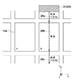
まず、従来の露光装置において、露光が行われなかったショット領域Bの露光を行う際における基板ステージ15の駆動について、図4を参照しながら説明する。図4は、従来の露光装置における基板ステージ15の駆動情報を示す図である。図4において、横軸は時刻を示し、縦軸は基板ステージ15のY方向への加速度を示す。また、従来の露光装置において、露光処理の際における基板ステージ15の駆動については図3を参照して説明する。制御部22は、ショット領域Aの露光を開始するまで、即ち、照射領域25がショット領域Aに差し掛かるまでは、基板ステージ15に+Y方向の加速度401を与える(図3の矢印26a)。これにより、基板ステージ15を+Y方向に加速させ、所定の速度にすることができる。基板ステージ15が所定の速度になった後では、制御部22は、照射領域25がショット領域Aを+Y方向に等速で走査するように基板ステージ15を等速で移動させる(図3の矢印26b)。そして、制御部22は、照射領域25がショット領域Aに差し掛かったときにショット領域Aの露光を開始し、照射領域25がショット領域Aを抜け出したときにショット領域Aの露光を終了する。図4においては、時間402が、ショット領域Aの露光が行われている時間である。照射領域25がショット領域Aを抜け出した後では、制御部22は、基板ステージ15に−Y方向の加速度403を与えることにより基板ステージ15を減速させる(図3の矢印26c)。そして、制御部22は、基板ステージ15が停止した後も基板ステージ15に−Y方向の加速度404を引き続き与えることにより基板ステージ15を−Y方向に加速させる(図3の矢印26d)。これにより、基板ステージ15を所定の速度にすることができる(図3の矢印26e)。しかしながら、図4に示す例では、ショット領域Aの露光が終了してから、ショット領域Bの露光が開始されるまでの期間421に、ショット領域Bの露光を行うための露光条件が整っていない。即ち、ショット領域Bの露光条件が整うまでに掛かる時間420が期間421より長くなってしまい、露光装置は時間405ではショット領域Bの露光を行うことができない。そのため、露光装置は、露光が行われなかったショット領域Bの露光を行う必要がある。そこで、従来の露光装置は、図5に示すように、照射領域25を位置27に配置し、照射領域25を位置27から−Y方向に走査してショット領域Bの露光を行う。
First, the driving of the
制御部22は、ショット領域Bの露光を行わずに照射領域25がショット領域Bを抜け出した後、基板ステージ15に+Y方向の加速度406を与えることにより基板ステージ15を減速させて停止させる(図3の矢印26f)。そして、制御部22は、基板ステージ15に+Y方向の加速度407を与えることで基板ステージ15を+Y方向に加速させ、基板ステージ15に−Y方向の加速度409を与えることで基板ステージ15を減速させて停止させる。これにより、照射領域25を位置27に配置することができる。その後、制御部22は、基板ステージ15に−Y方向の加速度410を与えることで基板ステージ15を加速させ(図5の矢印28a)、基板ステージ15を所定の速度にしてショット領域Bの露光を行う(図5の矢印28b)。図4では、時間411が、ショット領域Bの露光が行われている時間である。このように、従来の露光装置では、照射領域25を位置27に配置してから、ショット領域Bの露光が行われていた。
The
しかしながら、従来の露光装置のように、照射領域25を位置27に配置してショット領域Bの露光を行う場合では、期間421における基板ステージ15の駆動情報と、期間422における基板ステージ15の駆動情報とが異なってしまう。即ち、ショット領域Bの露光を開始するまでにおける基板ステージ15の駆動情報が異なってしまい、基板ステージ15の駆動に伴う装置の変形が期間421と期間422とで異なってしまう。そのため、ショット領域Bの露光を行うべき時間405におけるパターン像の状態と、実際にショット領域Bの露光が行われた時間411におけるパターン像の状態とが異なってしまう。したがって、時間411においてショット領域Bの露光を行う際に、事前に取得された補正値を用いてパターン像の状態を補正したとしても当該補正が不十分になってしまい、マスク11のパターンを正確に基板上に転写することが困難となってしまいうる。
However, when the
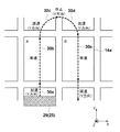
次に、第1実施形態の露光装置100において、露光が行われなかったショット領域Bの露光を行う際における基板ステージ15の駆動について、図6を参照しながら説明する。図6は、第1実施形態の露光装置における基板ステージ15の駆動情報を示す図である。第1実施形態の露光装置100では、露光が行われなかったショット領域Bの露光を行う際には、図7に示すように、照射領域25が位置29に配置される。そして、制御部22は、ショット領域Aを露光した時間402と、ショット領域Aの露光終了からショット領域Bの露光開始までの期間421とにおける基板ステージ15の駆動情報に従って基板ステージ15を再駆動してからショット領域Bの露光を行う。したがって、制御部22は、ショット領域Bの露光が行われるべき時間405の後、基板ステージ15に+Y方向の加速度206を与えることにより基板ステージ15を減速させるとともに、基板ステージ15を−X方向に移動させる。これにより、照射領域25は、時刻221において位置29に配置される。
Next, driving of the
照射領域25が位置29に配置された後、制御部22は、基板ステージに+Y方向の加速度207を与えることで基板ステージ15を加速させる(図7の矢印30a)。そして、制御部22は、基板ステージ15を所定の速度に保ちながら照射領域25にショット領域Aを通過させる(図7の矢印30b)。図6では、時間208が、照射領域25がショット領域Aを通過している時間である。ここで、ショット領域Aの露光は時間402において行われているため、制御部22は、時間208においてはショット領域Aの露光を行わない。
After the
照射領域25がショット領域Aを抜け出した後では、制御部22は、図6に示すように基板ステージ15に−Y方向の加速度209を与えることにより基板ステージを減速させる(図7の矢印30c)。制御部22は、基板ステージ15が停止した後も基板ステージ15に−Y方向の加速度210を引き続き与えることにより基板ステージ15を−Y方向に加速させる(図7の矢印30d)。そして、制御部22は、基板ステージ15を所定の速度にしてショット領域Bの露光を行う(図7の矢印30e)。図6では、時間211が、ショット領域Bの露光が行われている時間である。このように、第1実施形態の露光装置100は、露光条件が整わずに露光が行われなかったショット領域Bの露光を行う前に、期間421における基板ステージ15の駆動情報に従って基板ステージ15を再駆動する。これにより、基板ステージ15の駆動に伴う装置の変形を期間421と期間222とで近づけることができる。そのため、ショット領域Bの露光を行うべき時間405におけるパターン像の状態と、実際にショット領域Bの露光が行われた時間211におけるパターン像の状態とを近づけることができる。即ち、時間211においてショット領域Bの露光を行う際に、事前に取得された補正値を用いてパターン像の状態を補正することによって、マスク11のパターンをショット領域Bに正確に転写することが可能となる。
After the
上述したように、第1実施形態の露光装置100では、ショット領域Aの露光が終了してからショット領域Bの露光が開始されるまでの期間に露光条件が整わずにショット領域Bの露光が行われない場合がある。この場合、第1実施形態の露光装置100は、当該期間における基板ステージ15の駆動情報に従って基板ステージを再駆動してからショット領域Bの露光を行う。これにより、ショット領域Bの露光を行うべき時間におけるパターン像の状態と、実際にショット領域Bの露光が行われた時間におけるパターン像の状態とを近づけることができる。そのため、露光が行われなかったショット領域Bの露光を行う際に、事前に取得された補正値を用いてパターン像の状態を補正することができ、マスクのパターンをショット領域Bに正確に転写することが可能となる。
As described above, in the
ここで、第1実施形態の露光装置100では、図6および図7で説明したように、時間402と期間421とにおける基板ステージ15の駆動情報に従って基板ステージ15を再駆動してからショット領域Bの露光を行っているが、それに限られるものではない。ショット領域Bの露光を行う前に、ショット領域Aの露光終了からショット領域Bの露光開始までの期間421における基板ステージ15の駆動情報に少なくとも従って基板ステージを再駆動させればよい。また、第1実施形態の露光装置100では、ショット領域Bにおける照射領域25の走査が終了した直後に、照射領域25が位置29に配置されるように基板ステージ15を駆動しているが、それに限られるものではない。例えば、照射領域25が基板上における全てのショット領域上を走査した後で、照射領域25が位置29に配置されるように基板ステージ15を駆動してもよい。さらに、第1実施形態では、基板ステージ15の駆動情報に従って基板ステージ15を再駆動している際に、マスクステージ12についても、時間402と期間421とにおけるマスクステージ12の駆動情報に従って再駆動するとよい。
Here, in the
<第2実施形態>
第2実施形態では、ステップ・アンド・リピート方式の露光装置において、露光条件が整わずに露光が行われなかったショット領域を露光する方法について説明する。ステップ・アンド・リピート方式の露光装置では、ショット領域14aを露光する際に基板ステージ15を駆動せず、基板ステージ15が停止した状態でショット領域14aの露光が行われる。即ち、第2実施形態の露光装置では、光が照射される基板上の照射領域25がショット領域14aと同じ大きさとなる。ここで、第2実施形態の露光装置は、第1実施形態の露光装置100と装置構成が同様であるため、装置構成についての説明はここでは省略する。
Second Embodiment
In the second embodiment, a description will be given of a method of exposing a shot area in which exposure is not performed because exposure conditions are not satisfied in a step-and-repeat type exposure apparatus. In the step-and-repeat type exposure apparatus, when the
第2実施形態の露光装置において、露光処理の際における基板ステージ15の駆動情報について、図8および図9を参照しながら説明する。図8は、基板ステージ15を駆動させた際における基板ステージ15の駆動情報を示す図である。図9は、露光処理の際における基板ステージ15の駆動について説明するための図であり、図9には、照射領域25における中心の経路が示されている。ここで、第2実施形態の露光装置では、基板14に投影されたパターン像の状態を補正する補正値は、基板ステージ15を停止させてから所定の時間600が経過した後において取得される。
In the exposure apparatus of the second embodiment, drive information of the
制御部22は、基板ステージ15に+Y方向の加速度601を与えて基板ステージ15を加速させた(図9の矢印30a)後、基板ステージ15に−Y方向の加速度602を与えて基板ステージ15を減速させて(図9の矢印30b)停止させる。それにより、照射領域25がショット領域Aに配置される。そして、制御部22は、ショット領域Aの露光条件が整った後で、かつ基板ステージ15が停止してから所定の時間600(整定時間621)が経過した後に、ショット領域Aの露光を行う。図8において、時間611は、ショット領域Aの露光条件を整えている時間であり、時間612は、ショット領域Aの露光が行われている時間である。ショット領域Aの露光が終了した後、制御部22は、基板ステージ15に+Y方向の加速度603を与えて基板ステージ15を加速させる(図9の矢印30c)。そして、制御部22は、基板ステージ15に−Y方向の加速度604を与えて基板ステージ15を減速させて(図9の矢印30d)停止させる。これにより、照射領域25がショット領域Bに配置される。制御部22は、ショット領域Bの露光条件が整った後で、かつ基板ステージ15が停止してから所定の時間600が経過した後に、ショット領域Bの露光を行う。図8において、時間613は、ショット領域Bの露光条件を整えている時間であり、時間614は、ショット領域Bの露光を行うべき時間である。
The
しかしながら、図8に示すように、ショット領域Bの露光条件を整えている時間613が終了する時刻は、所定の時間600が終了する時刻よりも遅くなっている。即ち、ショット領域Bを露光する前における基板ステージ15の整定時間622は、所定の時間600より長くなってしまう。このような整定時間622をもってショット領域Bを時間614において露光してしまうと、補正値を取得した際におけるパターン像の状態と、時間614におけるパターン像の状態とが異なってしまう。そのため、制御部22は、時間614におけるショット領域Bの露光を止め、基板ステージ15に−Y方向の加速度605を与えた後、基板ステージに+Y方向の加速度606を与えることで、時刻624において照射領域25をショット領域Aに配置する。その後、制御部22は、照射領域25がショット領域Bに配置されるように、基板ステージに+Y方向の加速度607を与えることで基板ステージ15を+Y方向に加速する(図9の矢印30c)。そして、制御部22は、基板ステージ15に−Y方向の加速度608を与えることで基板ステージ15を−Y方向に減速させて(図9の矢印30d)停止させる。基板ステージ15が停止してから所定の時間600(整定時間623)が経過した後に、制御部22はショット領域Bの露光を行う。これにより、ショット領域Bの露光を行っている時間615におけるパターン像の状態を、補正値を取得した際におけるパターン像の状態に近づけることができる。したがって、時間615においてショット領域Bの露光を行う際に、事前に取得された補正値を用いてパターン像の状態を補正することによって、マスクのパターンをショット領域Bに正確に転写することが可能となる。
However, as shown in FIG. 8, the time when the
上述したように、第2実施形態の露光装置では、ショット領域Aの露光が終了してからショット領域Bの露光が開始されるまでの期間にショット領域Bの露光条件が整わない場合がある。この場合、第2実施形態の露光装置は、当該期間における基板ステージ15の駆動情報に従って基板ステージ15を再駆動してからショット領域Bの露光を行う。これにより、ショット領域Bを露光する前における整定時間を所定の時間600にすることができるため、ショット領域Bの露光を行う際に、事前に取得された補正値を用いてパターン像の状態を補正することができる。したがって、マスクのパターンをショット領域に正確に転写することが可能となる。
As described above, in the exposure apparatus according to the second embodiment, the exposure conditions for the shot area B may not be satisfied during the period from the end of the exposure of the shot area A to the start of exposure of the shot area B. In this case, the exposure apparatus of the second embodiment performs exposure of the shot region B after re-driving the
<物品の製造方法の実施形態>
本発明の実施形態にかける物品の製造方法は、例えば、半導体デバイス等のマイクロデバイスや微細構造を有する素子等の物品を製造するのに好適である。本実施形態の物品の製造方法は、基板に塗布された感光剤に上記の走査露光装置を用いて潜像パターンを形成する工程(基板を露光する工程)と、かかる工程で潜像パターンが形成された基板を現像する工程とを含む。更に、かかる製造方法は、他の周知の工程(酸化、成膜、蒸着、ドーピング、平坦化、エッチング、レジスト剥離、ダイシング、ボンディング、パッケージング等)を含む。本実施形態の物品の製造方法は、従来の方法に比べて、物品の性能・品質・生産性・生産コストの少なくとも1つにおいて有利である。
<Embodiment of Method for Manufacturing Article>
The method for manufacturing an article according to an embodiment of the present invention is suitable for manufacturing an article such as a microdevice such as a semiconductor device or an element having a fine structure. In the method for manufacturing an article according to the present embodiment, a latent image pattern is formed on the photosensitive agent applied to the substrate using the above-described scanning exposure apparatus (a step of exposing the substrate), and the latent image pattern is formed in this step. Developing the processed substrate. Further, the manufacturing method includes other well-known steps (oxidation, film formation, vapor deposition, doping, planarization, etching, resist stripping, dicing, bonding, packaging, and the like). The method for manufacturing an article according to the present embodiment is advantageous in at least one of the performance, quality, productivity, and production cost of the article as compared with the conventional method.
以上、本発明の好ましい実施形態について説明したが、本発明はこれらの実施形態に限定されないことはいうまでもなく、その要旨の範囲内で種々の変形および変更が可能である。 As mentioned above, although preferred embodiment of this invention was described, it cannot be overemphasized that this invention is not limited to these embodiment, A various deformation | transformation and change are possible within the range of the summary.
Claims (15)
マスクに形成されたパターンを前記基板に投影する投影光学系と、
前記第1ショット領域の露光の終了後、前記基板ステージを移動させ、前記第2ショット領域の露光を行うための露光条件が整った状態で前記第2ショット領域を露光するように制御を行う制御部と、
を有する露光装置において、
前記制御部は、
前記投影光学系の光軸方向に直交する方向に移動する前記基板ステージの加速度の情報に基づいて、前記第1ショット領域の露光の終了位置から前記第2ショット領域の露光の開始位置まで前記基板ステージを移動させる間に、前記第2ショット領域の露光を行うための露光条件が整わなかった場合には、
前記第2ショット領域を露光せず、前記情報に基づいて前記第1ショット領域の露光の終了位置から前記第2ショット領域の露光の開始位置まで再び前記基板ステージを移動させ、その後、前記第2ショット領域の露光を行う制御部であって、
前記情報に基づいて前記基板ステージを移動させながら予め取得された補正値を用いて、前記投影光学系により前記基板に投影されたパターン像の状態を補正しながら前記第2ショット領域を露光することを特徴とする露光装置。 A substrate stage capable of holding and moving the substrate including the first shot region and the second shot region ;
A projection optical system that projects the pattern formed on the mask onto the substrate;
Control for moving the substrate stage after the exposure of the first shot area and controlling the exposure of the second shot area in a state where the exposure conditions for performing the exposure of the second shot area are in place. And
In an exposure apparatus having
The controller is
The substrate from the exposure end position of the first shot area to the exposure start position of the second shot area based on the acceleration information of the substrate stage moving in a direction orthogonal to the optical axis direction of the projection optical system When the exposure conditions for performing exposure of the second shot area are not established while moving the stage,
Without exposing the second shot area, the substrate stage is moved again from the exposure end position of the first shot area to the exposure start position of the second shot area based on the information, and then the second shot area A control unit for performing exposure of a shot area,
Exposing the second shot region while correcting the state of the pattern image projected onto the substrate by the projection optical system using a correction value acquired in advance while moving the substrate stage based on the information. An exposure apparatus characterized by the above.
前記第1ショット領域の露光の終了後、前記基板ステージを移動させ、前記第2ショット領域の露光を行うための露光条件が整った状態で前記第2ショット領域を露光するように制御を行う制御部と、
を有する露光装置において、
前記制御部は、
前記基板ステージの駆動情報に基づいて、前記第1ショット領域の露光の終了位置から前記第2ショット領域の露光の開始位置まで前記基板ステージを移動させる間に、前記第2ショット領域の露光を行うための露光条件が整わなかった場合には、
前記第2ショット領域を露光せず、前記駆動情報に基づいて前記第1ショット領域の露光の終了位置から前記第2ショット領域の露光の開始位置まで再び前記基板ステージを移動させ、その後、前記第2ショット領域の露光を行うことを特徴とする露光装置。 A substrate stage capable of holding and moving the substrate including the first shot region and the second shot region;
Control for moving the substrate stage after the exposure of the first shot area and controlling the exposure of the second shot area in a state where the exposure conditions for performing the exposure of the second shot area are in place. And
In an exposure apparatus having
The controller is
Based on the drive information of the substrate stage, the second shot area is exposed while the substrate stage is moved from the exposure end position of the first shot area to the exposure start position of the second shot area. If the exposure conditions for
The second shot area is not exposed, and the substrate stage is moved again from the exposure end position of the first shot area to the exposure start position of the second shot area based on the drive information, and then the second shot area An exposure apparatus that performs exposure of a two-shot region.
請求項1乃至8のうちいずれか1項に記載の露光装置を用いて基板を露光する工程と、
前記工程で露光された前記基板を現像する工程と、
を含むことを特徴とする物品の製造方法。 In a method for manufacturing an article,
A step of exposing the substrate using the exposure apparatus according to any one of claims 1 to 8 ,
Developing the substrate exposed in the step;
A method for producing an article comprising:
前記第1ショット領域の露光の終了後、前記基板ステージを移動させ、前記第2ショット領域の露光を行うための露光条件が整った状態で前記第2ショット領域を露光するように制御を行う露光方法において、
駆動情報に基づいて前記第1ショット領域の露光の終了位置から前記第2ショット領域の露光の開始位置まで前記基板ステージを移動させる間に、前記第2ショット領域の露光を行うための露光条件が整わなかった場合には、
前記第2ショット領域を露光せずに、前記駆動情報に基づいて前記第1ショット領域の露光の終了位置から前記第2ショット領域の露光の開始位置まで再び前記基板ステージを移動させ、その後、前記第2ショット領域の露光を行う、
ことを特徴とする露光方法。 In exposing a substrate having a first shot region and a second shot region held on a movable substrate stage,
After completion of exposure of the first shot area, exposure is performed such that the substrate stage is moved and exposure is performed so that the second shot area is exposed with exposure conditions for performing exposure of the second shot area being prepared. In the method
An exposure condition for performing exposure of the second shot area while moving the substrate stage from the exposure end position of the first shot area to the exposure start position of the second shot area based on drive information is as follows. If not,
Without exposing the second shot area, the substrate stage is moved again from the exposure end position of the first shot area to the exposure start position of the second shot area based on the drive information, Exposure of the second shot area,
An exposure method characterized by the above.
請求項10乃至14のうちいずれか1項に記載の露光方法により基板を露光する工程と、
前記工程で露光された前記基板を現像する工程と、
を含むことを特徴とする物品の製造方法。 In a method for manufacturing an article,
A step of exposing the substrate by the exposure method according to any one of claims 10 to 14,
Developing the substrate exposed in the step;
A method for producing an article comprising:
Priority Applications (5)
| Application Number | Priority Date | Filing Date | Title |
|---|---|---|---|
| JP2013122024A JP5986538B2 (en) | 2013-06-10 | 2013-06-10 | Exposure apparatus and article manufacturing method |
| CN201611027383.7A CN106444300B (en) | 2013-06-10 | 2014-06-05 | Exposure device and the method for manufacturing article |
| CN201410245805.2A CN104238278B (en) | 2013-06-10 | 2014-06-05 | Exposure apparatus and method of manufacturing article |
| US14/299,244 US9557657B2 (en) | 2013-06-10 | 2014-06-09 | Exposure apparatus and method of manufacturing article |
| KR1020140069354A KR101784045B1 (en) | 2013-06-10 | 2014-06-09 | Exposure apparatus and method of manufacturing article |
Applications Claiming Priority (1)
| Application Number | Priority Date | Filing Date | Title |
|---|---|---|---|
| JP2013122024A JP5986538B2 (en) | 2013-06-10 | 2013-06-10 | Exposure apparatus and article manufacturing method |
Publications (3)
| Publication Number | Publication Date |
|---|---|
| JP2014239193A JP2014239193A (en) | 2014-12-18 |
| JP2014239193A5 JP2014239193A5 (en) | 2016-07-07 |
| JP5986538B2 true JP5986538B2 (en) | 2016-09-06 |
Family
ID=52005226
Family Applications (1)
| Application Number | Title | Priority Date | Filing Date |
|---|---|---|---|
| JP2013122024A Active JP5986538B2 (en) | 2013-06-10 | 2013-06-10 | Exposure apparatus and article manufacturing method |
Country Status (4)
| Country | Link |
|---|---|
| US (1) | US9557657B2 (en) |
| JP (1) | JP5986538B2 (en) |
| KR (1) | KR101784045B1 (en) |
| CN (2) | CN104238278B (en) |
Families Citing this family (1)
| Publication number | Priority date | Publication date | Assignee | Title |
|---|---|---|---|---|
| WO2020215274A1 (en) * | 2019-04-25 | 2020-10-29 | 深圳市大疆创新科技有限公司 | Unmanned aerial vehicle and image capture control method therefor |
Family Cites Families (23)
| Publication number | Priority date | Publication date | Assignee | Title |
|---|---|---|---|---|
| US5343270A (en) * | 1990-10-30 | 1994-08-30 | Nikon Corporation | Projection exposure apparatus |
| JPH06260384A (en) * | 1993-03-08 | 1994-09-16 | Nikon Corp | Method for controlling amount of exposure |
| US5617182A (en) * | 1993-11-22 | 1997-04-01 | Nikon Corporation | Scanning exposure method |
| US6118515A (en) * | 1993-12-08 | 2000-09-12 | Nikon Corporation | Scanning exposure method |
| JP3451604B2 (en) * | 1994-06-17 | 2003-09-29 | 株式会社ニコン | Scanning exposure equipment |
| JPH0992611A (en) * | 1995-09-21 | 1997-04-04 | Canon Inc | Scanning aligner and aligning method |
| JPH09115825A (en) * | 1995-10-19 | 1997-05-02 | Nikon Corp | Scanning type projection aligner |
| JP3514401B2 (en) | 1996-01-16 | 2004-03-31 | キヤノン株式会社 | Scanning exposure apparatus and method, and semiconductor device manufacturing method |
| JP3728610B2 (en) * | 1996-07-04 | 2005-12-21 | 株式会社ニコン | Scanning exposure apparatus and exposure method |
| US6646715B1 (en) * | 1997-01-14 | 2003-11-11 | Nikon Corporation | Scanning exposure apparatus and method with run-up distance control |
| JP3428872B2 (en) * | 1997-08-29 | 2003-07-22 | キヤノン株式会社 | Exposure method and apparatus |
| JPH11204421A (en) * | 1998-01-09 | 1999-07-30 | Nikon Corp | Aligner, method for controlling the same, exposure method, and manufacture of element |
| US6285438B1 (en) * | 1999-05-19 | 2001-09-04 | Nikon Corporation | Scanning exposure method with reduced time between scans |
| JP4585649B2 (en) * | 2000-05-19 | 2010-11-24 | キヤノン株式会社 | Exposure apparatus and device manufacturing method |
| JP2002110526A (en) * | 2000-10-03 | 2002-04-12 | Canon Inc | Method and system for scanning alignment |
| KR100585108B1 (en) * | 2003-11-14 | 2006-06-01 | 삼성전자주식회사 | Method for exposing wafer using scan type exposure apparatus |
| JP4625673B2 (en) * | 2004-10-15 | 2011-02-02 | 株式会社東芝 | Exposure method and exposure apparatus |
| KR20070122445A (en) * | 2005-04-28 | 2007-12-31 | 가부시키가이샤 니콘 | Exposure method, exposure apparatus and device manufacturing method |
| US8330936B2 (en) * | 2006-09-20 | 2012-12-11 | Asml Netherlands B.V. | Lithographic apparatus and device manufacturing method |
| JP2009010202A (en) * | 2007-06-28 | 2009-01-15 | Canon Inc | Exposure method, exposure device, and device manufacturing method |
| JP5489534B2 (en) * | 2009-05-21 | 2014-05-14 | キヤノン株式会社 | Exposure apparatus and device manufacturing method |
| JP5498243B2 (en) | 2010-05-07 | 2014-05-21 | キヤノン株式会社 | Exposure apparatus, exposure method, and device manufacturing method |
| JP5406861B2 (en) * | 2011-01-01 | 2014-02-05 | キヤノン株式会社 | Exposure apparatus and device manufacturing method |
-
2013
- 2013-06-10 JP JP2013122024A patent/JP5986538B2/en active Active
-
2014
- 2014-06-05 CN CN201410245805.2A patent/CN104238278B/en active Active
- 2014-06-05 CN CN201611027383.7A patent/CN106444300B/en active Active
- 2014-06-09 US US14/299,244 patent/US9557657B2/en active Active
- 2014-06-09 KR KR1020140069354A patent/KR101784045B1/en active IP Right Grant
Also Published As
| Publication number | Publication date |
|---|---|
| US20140362357A1 (en) | 2014-12-11 |
| CN104238278B (en) | 2017-01-11 |
| CN104238278A (en) | 2014-12-24 |
| KR20140144145A (en) | 2014-12-18 |
| US9557657B2 (en) | 2017-01-31 |
| JP2014239193A (en) | 2014-12-18 |
| CN106444300B (en) | 2018-08-14 |
| CN106444300A (en) | 2017-02-22 |
| KR101784045B1 (en) | 2017-10-10 |
Similar Documents
| Publication | Publication Date | Title |
|---|---|---|
| JP5498243B2 (en) | Exposure apparatus, exposure method, and device manufacturing method | |
| JP6267530B2 (en) | Exposure apparatus and article manufacturing method | |
| JP5137879B2 (en) | Exposure apparatus and device manufacturing method | |
| CN109100920B (en) | Exposure apparatus and method for manufacturing article | |
| TWI477923B (en) | Lithographic apparatus and lithographic projection method | |
| JP2013110407A (en) | Reticle assembly, lithographic apparatus, use thereof in lithographic process, and method of projecting two or more image fields in single scanning movement of lithographic process | |
| JP5986538B2 (en) | Exposure apparatus and article manufacturing method | |
| TWI509369B (en) | Exposure method, exposure apparatus, and method of manufacturing device | |
| JP2010123755A (en) | Exposure apparatus, and device manufacturing method | |
| JP5489534B2 (en) | Exposure apparatus and device manufacturing method | |
| US9329498B2 (en) | Exposure apparatus and method of manufacturing article | |
| JP6861503B2 (en) | Scanning exposure device, its control method, and article manufacturing method | |
| JP2016513276A (en) | Lithographic apparatus and device manufacturing method | |
| JP2015201526A (en) | Profile generation method, exposure equipment and device manufacturing method | |
| JP6338377B2 (en) | Exposure apparatus and article manufacturing method | |
| JP6581417B2 (en) | Exposure apparatus, exposure method, and article manufacturing method | |
| JP2014143429A (en) | Exposure device, exposure method, and device manufacturing method | |
| JPH1092727A (en) | Projection aligner | |
| TW550668B (en) | Stage apparatus, exposure system and device production method | |
| JP2017156512A (en) | Exposure equipment and manufacturing method of article | |
| JP6053316B2 (en) | Lithographic apparatus and article manufacturing method | |
| JP6701597B2 (en) | Exposure apparatus, exposure method, flat panel display manufacturing method, and device manufacturing method | |
| JP2006190776A (en) | Plotter | |
| JP2014239193A5 (en) | ||
| KR20200109261A (en) | Exposure apparatus and article manufacturing method |
Legal Events
| Date | Code | Title | Description |
|---|---|---|---|
| A521 | Written amendment |
Free format text: JAPANESE INTERMEDIATE CODE: A523 Effective date: 20160517 |
|
| A621 | Written request for application examination |
Free format text: JAPANESE INTERMEDIATE CODE: A621 Effective date: 20160517 |
|
| A871 | Explanation of circumstances concerning accelerated examination |
Free format text: JAPANESE INTERMEDIATE CODE: A871 Effective date: 20160517 |
|
| A975 | Report on accelerated examination |
Free format text: JAPANESE INTERMEDIATE CODE: A971005 Effective date: 20160602 |
|
| TRDD | Decision of grant or rejection written | ||
| A01 | Written decision to grant a patent or to grant a registration (utility model) |
Free format text: JAPANESE INTERMEDIATE CODE: A01 Effective date: 20160708 |
|
| A61 | First payment of annual fees (during grant procedure) |
Free format text: JAPANESE INTERMEDIATE CODE: A61 Effective date: 20160805 |
|
| R151 | Written notification of patent or utility model registration |
Ref document number: 5986538 Country of ref document: JP Free format text: JAPANESE INTERMEDIATE CODE: R151 |