JP5982184B2 - Telescopic flexible joint - Google Patents
Telescopic flexible joint Download PDFInfo
- Publication number
- JP5982184B2 JP5982184B2 JP2012125063A JP2012125063A JP5982184B2 JP 5982184 B2 JP5982184 B2 JP 5982184B2 JP 2012125063 A JP2012125063 A JP 2012125063A JP 2012125063 A JP2012125063 A JP 2012125063A JP 5982184 B2 JP5982184 B2 JP 5982184B2
- Authority
- JP
- Japan
- Prior art keywords
- joint
- joint pipe
- annular spacer
- expansion
- ball
- Prior art date
- Legal status (The legal status is an assumption and is not a legal conclusion. Google has not performed a legal analysis and makes no representation as to the accuracy of the status listed.)
- Active
Links
- 125000006850 spacer group Chemical group 0.000 claims description 74
- 230000002093 peripheral effect Effects 0.000 claims description 38
- 230000008602 contraction Effects 0.000 claims description 35
- 238000003780 insertion Methods 0.000 claims description 14
- 230000037431 insertion Effects 0.000 claims description 14
- XLYOFNOQVPJJNP-UHFFFAOYSA-N water Substances O XLYOFNOQVPJJNP-UHFFFAOYSA-N 0.000 description 10
- 238000000926 separation method Methods 0.000 description 5
- 239000002184 metal Substances 0.000 description 3
- 239000011347 resin Substances 0.000 description 3
- 229920005989 resin Polymers 0.000 description 3
- BZHJMEDXRYGGRV-UHFFFAOYSA-N Vinyl chloride Chemical compound ClC=C BZHJMEDXRYGGRV-UHFFFAOYSA-N 0.000 description 2
- 230000004323 axial length Effects 0.000 description 2
- 238000007789 sealing Methods 0.000 description 2
- 230000002159 abnormal effect Effects 0.000 description 1
- 230000005489 elastic deformation Effects 0.000 description 1
- 230000001747 exhibiting effect Effects 0.000 description 1
- 238000004519 manufacturing process Methods 0.000 description 1
- 239000000463 material Substances 0.000 description 1
- 238000000034 method Methods 0.000 description 1
- 230000000087 stabilizing effect Effects 0.000 description 1
- 125000000391 vinyl group Chemical group [H]C([*])=C([H])[H] 0.000 description 1
- 229920002554 vinyl polymer Polymers 0.000 description 1
Images


Landscapes
- Joints Allowing Movement (AREA)
Description
本発明は、主として水道配管に用いられ、通常の使用において一定距離の伸縮性とスイング性を有し、やや高い水圧変動や外力によって生ずる配管の伸縮を吸収して配管系の損傷を防止するほかにも、異常に高い水圧や外力が加わった時に、これによって生ずる過大な伸長も吸収して、管や器具が損傷することを防ぐことができる伸縮可撓継手に関する。 The present invention is mainly used for water pipes, has a stretchability and a swing property for a certain distance in normal use, and absorbs the expansion and contraction of piping caused by a slightly high water pressure fluctuation and external force to prevent damage to the piping system. In particular, the present invention relates to an expansion / contraction flexible joint that can absorb excessive elongation caused by an abnormally high water pressure or external force and prevent damage to a pipe or instrument.
水道配管に用いられる可撓継手は、配管の伸縮を吸収することで管や管継手、バルブ等の器具の損傷を防ぐことが可能になっている。その際、可撓継手が多少の加圧変化でも伸縮可能な構造になっていると、配管完了後の圧力変化等で最大に伸長し、この状態で外力が加わったときに更に伸長できなくなる。この場合、配管や塩ビ管ビニール等の継手に損傷や破断が生じ、漏れなどの不具合を生じることにもつながる。 Flexible joints used for water supply pipes can prevent damage to equipment such as pipes, pipe joints, and valves by absorbing expansion and contraction of the pipes. At that time, if the flexible joint has a structure that can be expanded and contracted even by a slight change in pressure, the flexible joint expands to the maximum due to a pressure change after completion of piping, and cannot be further expanded when an external force is applied in this state. In this case, damage and breakage occur in joints such as piping and vinyl chloride pipe vinyl, leading to problems such as leakage.
このような不具合を防ぐようにした伸縮継手として、例えば、特許文献1のスイングジョイントが知られている。このスイングジョイントにおいては、継手パイプに溝加工し、この溝部分とユニオンソケットとの間に負荷剪断リングが設けられた構造になっている。このスイングジョイントでは、負荷が加わりこの負荷がある一定以上の値を超えると、負荷剪断リングが破断することで継手パイプが伸縮するようになっている。
特許文献2の伸縮継手においては、軸線方向に切欠き部を設けた筒状のスペーサリングが、継手パイプ外周面の鍔部とシール部との間に嵌装されている。この伸縮継手に一定以上の負荷が加わったときには、スペーサリングの円筒部が継手パイプに押されて圧縮され、外周方向に切欠き部が拡径するようになっている。スペーサリングは弾性変形によって鍔部との係合が外れ、継手パイプが伸縮する構造になっている。
For example, a swing joint disclosed in
In the expansion joint of
これらは、特に伸縮可とう継手と呼ばれ、可とう角を有するボールジョイント構造になっている。このボールジョイント構造により、例えば、片側7〜15°程度の可とう角を有し、また、1.75MPa以上の異常な水圧もしくは相当する外力が加わると、継手パイプが伸縮するようになっている。これにより、一般的な伸縮継手に比べて地盤変動などの応力をより吸収できるようになっている。 These are particularly called elastic flexible joints, and have a ball joint structure having a flexible angle. With this ball joint structure, for example, the joint pipe has a flexible angle of about 7 to 15 ° on one side, and the joint pipe expands and contracts when an abnormal water pressure of 1.75 MPa or more or a corresponding external force is applied. . Thereby, compared with a general expansion joint, stress, such as ground fluctuation, can be absorbed more.
しかしながら、特許文献1のスイングジョイントにおいては、継手パイプに溝加工を施す必要があるため、この溝を設けることで継手パイプの強度が低下していた。更に、溝加工をユニオンソケットに施す必要もあり、この溝やボールスリーブへの挿入用のテーパをユニオンソケットに設けることから、JIS規格品のユニオンソケットをそのまま使用することができなくなっていた。負荷剪断リングが一定以上の負荷により破断した場合には、その都度負荷剪断リングを交換する必要が生じることになり、しかも、負荷剪断リングの装着時には、継手パイプ外周面とボール内周面との間に配置し、かつ継手パイプに溝加工を施す必要もあるために組立てに手間がかかっていた。スイングジョイントに連続振動が加わると、ボールスリーブとジョイント本体並びにキャップが接触し、これらの金属面同士に摩耗が発生して消耗が激しくなっていた。
However, in the swing joint of
一方、特許文献2の伸縮継手においては、スペーサリングを拡径しやすくするために切欠き部を設けているため、この切欠き部に負荷が集中して均等に耐圧がかかりにくくなる。そのため、継手パイプが傾斜等で可撓すると簡単にスペーサリングが拡径して係合が外れることで最伸長状態になるおそれがあった。この伸縮継手は、ボール部の構造が複雑であり、組立ても困難であった。
On the other hand, in the expansion joint of
本発明は、従来の課題を解決するために開発したものであり、その目的とするところは、継手パイプに追加工を施すことなくこの継手パイプを接続でき、接続後に所定を越える力が加わった場合に、荷重を効果的に分散しながら継手パイプの伸縮を吸収して継手部分や配管の損傷を防ぎ、部品を交換することなく簡単な内部構造で組立ても容易で、しかも伸縮性と可撓性を良好にした伸縮可撓継手を提供することにある。 The present invention has been developed to solve the conventional problems, and the purpose of the present invention is to connect the joint pipe without any additional work on the joint pipe, and a force exceeding a predetermined value is applied after the connection. In this case, it is easy to assemble with a simple internal structure without replacing parts by absorbing the expansion and contraction of the joint pipe while effectively distributing the load to prevent damage to the joint part and piping, and it is also stretchable and flexible An object of the present invention is to provide an expansion / contraction flexible joint with improved properties.
上記目的を達成するため、請求項1に係る発明は、継手本体に挿入側先端に鍔部を設けた継手パイプを伸縮自在に水密状態に保持された伸縮可撓継手であって、前記継手パイプの鍔部の根本部分の外周側に装着した環状スペーサと、前記継手パイプの外周に装着し、かつ継手本体の開口側内周に配設されたボール形状部とを有し、このボール形状部には、内周側に環状スペーサの外径より小さく形成された円周隙間と、この円周隙間の奥側位置に環状スペーサの外径より僅かに大きく形成された円周段差とを備え、通常時に、前記環状スペーサの一端側を鍔部に、他端側を前記円周段差にそれぞれ当接させ、前記継手パイプが軸方向に所定を超える力が付与されたとき、前記環状スペーサが前記円周隙間の奥側位置に圧入されるように構成した伸縮可撓継手である。
To achieve the above object, a first aspect of the present invention, there is provided a telescopic flexible joint which is held a joint pipe provided with a flange portion on the insertion side leading end to the joint body freely in watertight expansion, the joint pipe An annular spacer mounted on the outer peripheral side of the root portion of the flange portion, and a ball-shaped portion mounted on the outer periphery of the joint pipe and disposed on the inner periphery of the joint body on the opening side. the includes inner and circumferential gap which is smaller fence than the outer diameter of the annular spacer in the peripheral side, and a circumferential step which is slightly larger than the outer diameter of the annular spacer to the rear side position of the circumferential gap In a normal state, when one end side of the annular spacer is in contact with the flange and the other end side is in contact with the circumferential step, and the joint pipe is applied with a force exceeding a predetermined amount in the axial direction, the annular spacer configured to be press-fitted to the back side position of the circumferential gap It is a telescopic flexible joint.
請求項2に係る発明は、継手本体に挿入側先端に鍔部を設けた継手パイプを伸縮自在に水密状態に保持された伸縮可撓継手であって、前記継手パイプの鍔部の根本部分の外周側に一体に設けられた環状スペーサと、前記継手パイプの外周に装着し、かつ継手本体の開口側内周に配設されたボール形状部とを有し、このボール形状部には、内周側に環状スペーサの外径より小さく形成された円周隙間と、この円周隙間の奥側位置に環状スペーサの外径より僅かに大きく形成された円周段差とを備え、通常時に、前記環状スペーサの端部側を前記円周段差に当接させ、前記継手パイプが軸方向に所定を超える力が付与されたとき、前記環状スペーサが前記円周隙間の奥側位置に圧入されるように構成したことを特徴とする伸縮可撓継手である。
The invention according to
請求項3に係る発明は、環状スペーサの円周段差側の角部にアール部又はテーパ面を形成し、一方、円周段差の環状スペーサの当接側にアール部又はテーパ面を形成した伸縮可撓継手である。
In the invention according to
請求項4に係る発明は、筒状部材の外周をボール形状に形成し、このボール形状部の外周と継手本体の開口側内周との間にOリングを装着すると共に、筒状部材の内周と継手パイプの外周との間にOリングを装着した伸縮可撓継手である。
In the invention according to
請求項1又は請求項2に係る発明によると、継手パイプの鍔部の根元部分に設けた環状スペーサにより、継手パイプに追加工や特殊な加工を施すことなく継手パイプを接続でき、接続後には所定を越える力が加わったときに、筒状部材に設けた円周隙間の奥側位置に環状スペーサが圧入して伸長代を介して継手パイプの離脱方向の伸長を吸収する。更に、継手パイプの挿入方向にも伸縮代を設けることができ、この場合、高い水圧変動や外力によって生ずる配管の伸縮を吸収する。これらにより、荷重を効果的に分散しながら継手パイプの伸縮を吸収して継手部分や配管の損傷を防ぐことができ、部品を交換することなく伸縮性と可撓性を良好にできる。しかも、内部構造を簡略化でき、組立ても容易になる。さらには、筒状部材の内周に円周隙間と円周段差を設けることにより、継手パイプと筒状部材との接触領域が減り、継手パイプ引き抜き時においても筒状部材とのシール状態が維持される。しかも、通常時には環状スペーサが円周段差に当接しているため、継手パイプの位置を保持して安定した接続状態を維持できる。この状態で水圧変動や外力により継手パイプの離脱方向に力が加わったときには、環状スペーサが徐々に筒状部材に設けた円周隙間の奥側位置に圧入され、応力が均等に分散された状態で離脱荷重の安定化を図りながら継手パイプの伸長を吸収できる。これにより継手パイプの瞬時の伸長を防止して継手本体や継手パイプの損傷を回避できる。
According to the invention according to
請求項3に係る発明によると、環状スペーサと筒状部材のアール部やテーパ面の当接によって継手パイプの離脱方向に力が加わった瞬間の摺動抵抗を著しく減少でき、円周隙間への継手パイプの急激な圧入を防いで継手本体や継手パイプの損傷を防ぐことができる。 According to the third aspect of the invention, the sliding resistance at the moment when force is applied in the disengagement direction of the joint pipe by the contact between the annular spacer and the rounded portion of the tubular member or the tapered surface can be remarkably reduced. It is possible to prevent the joint body and the joint pipe from being damaged by preventing rapid press-fitting of the joint pipe.
請求項4に係る発明によると、継手パイプの接続後に、筒状部材を用いたボールジョイント構造によって適宜の可撓角による可動を許容でき、しかも、ボール形状部の外周と継手本体の開口側内周との間、継手本体の内周と継手パイプの外周との間にそれぞれOリングを装着していることで接続後のシール性を確保している。
According to the invention of
以下に、本発明における伸縮可撓継手の実施形態を図面に基づいて詳細に説明する。
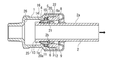
図1においては、本発明における伸縮可撓継手の半截断面図を示しており、図2においては、図1の要部拡大断面図を示している。
Hereinafter, an embodiment of an expansion / contraction flexible joint according to the present invention will be described in detail with reference to the drawings.
FIG. 1 shows a half-sectional view of the expansion / contraction flexible joint according to the present invention, and FIG. 2 shows an enlarged cross-sectional view of the main part of FIG.
図において、本発明の伸縮可撓継手は、継手本体1を有し、この継手本体1に継手パイプ2をシールして伸縮自在に水密保持するものである。継手本体1には、筒状部材3、環状スペーサ4、Oリング5、6、ボールシート7、ブッシュ状のキャップ8、カバー9を介して継手パイプ2が保持可能となる。継手本体1において、開口側内周にはOリング5及びリング状のボールシート7装着用の装着凹部11が形成され、この装着凹部11よりも開口側にはめねじ12が形成されている。
In the figure, the expansion / contraction flexible joint of the present invention has a
図1の継手パイプ2は、例えば、塩ビ管等の樹脂管からなり、継手本体1への挿入側先端には鍔部13が設けられている。この鍔部13の根本部分には、別体に設けた環状スペーサ4が装着される。環状スペーサ4は、例えば、継手本体1と同一材料の樹脂により形成され、一側が鍔部13側面の当接面14に当接した状態で継手パイプ2に装着される。
The
筒状部材3は金属製からなり、継手パイプ2の外周側に装着可能に設けられる。筒状部材3は、継手本体1の開口側内周側に配設され、図2に示すように、内周側には環状スペーサ4の外径Dsよりも小さい内径dtからなる円周隙間15が形成されている。この構造によって伸縮可撓継手に継手パイプ2が保持可能に設けられ、継手パイプ2の軸芯Pの方向に所定を越える力が付与されたときに環状スペーサ4が円周隙間15の奥側位置に圧入して、継手パイプ2が図における右方向の離脱方向に移動するようになっている。
The
筒状部材3に設けた円周隙間15の奥側位置には円周段差16が設けられ、この円周段差16の内径dwは、環状スペーサ4の外径Dsよりも僅かに大きい径に設けられている。継手パイプ2を継手本体1によって保持する場合、通常時においては、前記の環状スペーサ4の鍔部13側でない他側が円周段差16に当接した状態に配置される。
A
ここで、上記の環状スペーサ4の円周段差16側の角部にはアール部又はテーパ面が形成され、一方、円周段差16の環状スペーサ4の当接側にもアール部又はテーパ面が形成されている。本実施形態では、図2に示すように、円周段差16側の角部にテーパ面17が形成され、一方、環状スペーサ4の当接側にアール部18が形成されている。更に、テーパ面17の円周隙間15からの角度αを45°とし、アール部18の大きさをR0.5mmとした。環状スペーサ4の筒状部材3への装着時には、これらのテーパ面17とアール部18とが当接した状態になる。
Here, a rounded portion or a tapered surface is formed at a corner portion of the
筒状部材3の外周には、ボール形状からなるボール形状部20が形成されている。ボール形状部20の外周面20aと継手本体1の開口側内周の装着凹部11との間には、Oリング5、ボールシート7が装着されている。一方、筒状部材3の内周には装着凹溝21が形成され、この装着凹溝21と継手パイプ2の外周2aとの間にOリング6が装着されている。Oリング5やOリング6は、他の形状のシール部材を用いてもよい。
A ball-shaped
図1に示したキャップ8は、環状に形成され、このキャップ8の継手本体1取付け側には、めねじ12に螺着可能なおねじ22が形成されている。キャップ8は、おねじ22とめねじ12との螺着によって継手本体1の開口側に取付けられる。前記ボールシート7は、キャップ8とボール形状部20側のOリング5との間に設けられ、このボールシート7の内周側がボール形状部20の外周面20aに当接した状態になっている。図2に示すように、ボールシート7の装着により、ボール形状部20と継手本体1の開口側内周部1aと間に隙間23、ボール形状部20とキャップ8のボール形状部側の内周部8aとの間に隙間24がそれぞれ形成される。また、ボールシート7の外周側端部は、継手本体1の内部に設けられた段部に当接し、この段部とキャップ8との間で挟持される。
カバー9は、一体化した継手本体1とキャップ8の外周に取付けられ、組立て後の伸縮可撓継手の継手パイプ2装着側を保護している。
The
The
伸縮可撓継手を組付ける場合には、先ず、Oリング6を装着凹溝21に設けた筒状部材3に環状スペーサ4を装着した継手パイプ2を挿入する。この場合、筒状部材3の内周側にOリング6以外の突起部位がないため、継手パイプ2の端部側にテーパ部位を設けることなくOリング6の弾性力に抗しながらスムーズに継手パイプ2を挿入できる。この筒状部材3、Oリング6、環状スペーサ4を一体化した継手パイプ2を、Oリング5、ボールシート7を装着凹部11に装着した継手本体1の開口側から挿入する。このとき、前述のように、環状スペーサ4の一側が継手本体の根本部分である鍔部13側面の当接面14に当接し、他側が円周段差に当接した状態で、継手パイプ2、環状スペーサ4、Oリング6を装着した筒状部材3が一体的に挿入される。
When assembling the expansion / contraction flexible joint, first, the
次いで、継手本体1にキャップ8をめねじ12とおねじ22との螺着により一体化する。螺着後には、ボール形状部20が円弧面である継手本体1の開口側内周部1aと、キャップ8の内周面8aとによって位置決めされ、筒状部材3が継手本体1とキャップ8との間に保持される。
Next, the
継手本体1、キャップ8の外周側に開口側からカバー9を装着することで図1の状態に組付けられる。この組付け後には、環状スペーサ4を設けた継手パイプ2が継手本体1に対して摺動可能となり、鍔部13が筒状部材3に係止可能な径に形成されていることで、継手パイプ2は、筒状部材3、Oリング5、6、ボールシート7、キャップ8により抜け止め状態で水密保持される。
The
図1において、通常時においては、環状スペーサ4は、鍔部13側の一側が鍔部13の当接面14に当接し、筒状部材3側の他側の一部が円周段差16に当接して円周隙間15に収納された状態で装着されている。このとき、鍔部13の当接面14から筒状部材3の先端側までの距離が、継手パイプ2の離脱方向における伸長代L1となる。一方、鍔部13の外端面25から継手本体内部に形成された当接部26までの距離が、継手パイプ2の挿入方向における伸縮代L2となる。伸縮可撓継手に水圧変動や外力が加わった場合、伸長代L1と伸縮代L2との和によって継手パイプ2の伸縮を吸収できる。
In FIG. 1, in the normal state, the
図3においては、継手パイプ2が軸芯Pを中心に可撓した状態を示している。軸芯Pに対する継手パイプ2の可撓角θは略10°であり、この可撓角θの範囲内で伸縮を吸収することが可能になる。可撓時には、前述のようにボールシート7の内周側をボール形状部20の外周面20aに当接すると共に、このボール形状部20と、継手本体1の開口側内周部1aとキャップ8のボール形状部20側の内周部との間にそれぞれ隙間23、24を形成しているので、筒状部材3と、継手本体1及びキャップ8との金属面同士の接触を阻止し、これらの摩耗を確実に防止する。このため、筒状部材3によるスムーズな可撓性を維持し、軸芯Pを中心としたときの可撓性を確実に発揮する。なお、後述する継手パイプ1の離脱及び挿入方向の伸縮時においても、通常時と同様の可撓角θを維持できる。
FIG. 3 shows a state in which the
図4においては、継手パイプ2が、図1の伸長代L1により離脱方向に伸長した状態を示している。図に示すように、過度な水圧や外力が加わり、軸芯P方向に所定を越える離脱力が付与されたときには、環状スペーサ4が円周隙間15に圧入されることで、伸長代L1において継手パイプ2の離脱方向の伸縮を許容できる。
FIG. 4 shows a state in which the
環状スペーサ4の外径は、円周隙間15の内径よりも大きいことから、環状スペーサ4は、円周段差16のアール部18又はテーパ面17にガイドされて、縮径されながら円周隙間15内に徐々に圧入される。従って、継手パイプ2は、ブレーキをかけられながら伸長する状態となり、安定して瞬時の伸長が防止され、継手本体1や継手パイプ2の損傷を回避することができる。
Since the outer diameter of the
本実施形態においては、円周隙間15の軸方向の長さを、環状スペーサ4の軸方向長さと略同じに設定している。従って、図4に示すように、継手パイプ2が伸長代L1により伸長すると、環状スペーサ4は、円周隙間15に完全に収容され、継手パイプ2の鍔部13が筒状部材3の側面に当接する。
In the present embodiment, the axial length of the
図5においては、継手パイプ2が、図1の伸縮代L2により挿入方向に短縮した状態を示している。このように、過度な水圧や外力が加わり、軸芯P方向に所定を越える挿入力が付与された場合には、継手パイプ1の鍔部13の外端面25が継手本体1の当接部26に当接するまで摺動することで、伸縮代L2において継手パイプ2の挿入方向の伸縮を許容できる。
FIG. 5 shows a state in which the
上述したように、本発明の上記実施形態における伸縮可撓継手は、継手パイプ2の鍔部13の根本部分に環状スペーサ4を設け、継手パイプ2に装着した筒状部材3を継手本体1の開口側内周部1aに配設し、筒状部材3の内周側に円周隙間15を形成し、継手パイプ2が軸芯P方向に所定を越える力が付与されたときに環状スペーサ4が円周隙間15の奥側位置に圧入するようにしているので、継手パイプ2に溝加工等の追加工を施す必要がなく、JIS規格品の継手パイプ2をそのまま使用できる。そのため、継手パイプ2の強度の低下を防ぐこともでき、組立時においては、この圧入方式の継手パイプ2を用いることで複雑な組立て作業を実施することなく容易に組立でき、作業ミスを減らすこともできる。
As described above, the expansion / contraction flexible joint according to the above embodiment of the present invention is provided with the
継手パイプ2の伸縮を確実に吸収でき、特に、図4における継手パイプ2の離脱方向への伸長時には、45°に設けたテーパ面17とR0.5mmに設けたアール部18とが当接するため、環状スペーサ4が円周隙間15に均等に圧入される。これによって、応力が一箇所に集中することを防ぎ、安定した離脱荷重を発揮しながら継手パイプ2を伸長して配管等の損傷を防止できる。このとき、環状スペーサ4が徐々に円周隙間15の奥側位置に圧入されることで瞬時に伸縮することが防がれるため、継手本体1や継手パイプ2に損傷を与える危険性が少なくなる。環状スペーサ4の円周段差16側の角部にテーパ面17、環状スペーサ4の当接側にアール部18を設けることで所定の外力が加わったときに圧入による伸長機能を効率的に発揮することができるが、これに限らず、環状スペーサ4の円周段差16側の角部及び円周段差16の環状スペーサ4の当接側に、アール部又はテーパ面を所定の組み合わせで設けた場合にも同様の機能が発揮される。
The expansion and contraction of the
筒状部材3の内周に円周隙間15を設けた構成としていることで、継手パイプ2と筒状部材3との接触領域が減り、継手パイプ2の引き抜き時においても、環状スペーサ4の外周面によって円周隙間15が傷付くことが防がれ、筒状部材3とのシール状態が確保される。そのため、継手パイプ2の伸長時の漏れを確実に防止できる。
Since the
このシール性の確保について、以下に詳しく説明する。
筒状部材3の内周には、Oリング6の装着凹溝21が形成されている。そして、この装着凹溝21よりも継手パイプ2の先端側(鍔部13側)に、円周隙間15を設けている。これにより、装着凹溝21と円周隙間15との間には、装着凹溝21を構成する壁部21aが形成されている。
The securing of this sealing property will be described in detail below.
A mounting
この壁部21aは、Oリング6よりも継手パイプ2の先端側において、筒状部材3の内周と継手パイプ2の外周が接触し得る、唯一の領域となる。従って、継手パイプ2の外周が筒状部材3の内周に接触し得る領域を最小限に絞ることができ、継手パイプ2の外周が損傷するのを抑制し、継手パイプ2の伸長過程におけるシール性を確保することができる。
This
また、本発明の伸縮可撓継手は、継手パイプ2の伸長前の状態(図1、図2参照)において、伸長代L1分の伸長時(図4参照)にOリング6と接することとなる継手パイプ2の外周領域2bが、筒状部材3の円周隙間15に対向するよう構成されている。従って、この外周領域2bが筒状部材3の内周に接することがなく、損傷の可能性が極めて少ないため、従来の伸縮可撓継手と同様の伸長代L1を確保しつつ、伸長時におけるシール性を十分に確保することができる。
Moreover, the expansion-contraction flexible joint of this invention will contact | connect the O-
図6においては、本発明の伸縮可撓継手の第2実施形態を示している。なお、この実施形態以降において、前記実施形態と同一箇所は同一符号によって表し、その説明を省略する。この実施形態の伸縮可撓継手は、継手本体30、筒状のリング体で形成した筒状部材31、シールリング32、シールカバー33、袋ナット34を有している。この伸縮可撓継手では、前記実施形態と同様に継手パイプ2の鍔部13の根本部分に別体の環状スペーサ4を設け、筒状部材31を継手本体30の内周側に形成した段部面35に装着したものである。筒状部材31には円周隙間15、円周段差16が設けられ、通常時には円周段差16に環状スペーサ4が当接された状態で装着されている。
In FIG. 6, 2nd Embodiment of the expansion-contraction flexible joint of this invention is shown. In the following embodiments, the same parts as those in the above embodiments are denoted by the same reference numerals, and the description thereof is omitted. The expansion / contraction flexible joint of this embodiment includes a
更に、筒状部材31の装着側から、シールリング32、シールカバー33を介して袋ナット34が螺着されている。これによって、継手本体30、袋ナット34の内側に環状スペーサ4を有する継手パイプ2、筒状部材31、シールリング32、シールカバー33が装着されている。
Further, a
この伸縮可撓継手は、継手本体30に継手パイプ2をシールリング32によってシールしながら、この継手パイプ2が軸芯P方向に所定を越える力が付与されたときに環状スペーサ4が円周隙間15の奥側位置に圧入するようになっており、継手パイプ2の鍔部13が、袋ナット34、シールカバー33、シールリング32と、平常は環状スペーサ4とを介して抜け止め、かつ水密支持しながら継手パイプ2の離脱方向の伸縮を伸長代L1によって吸収する。一方、継手パイプ2の挿入方向にも伸縮代L2を設けていることから、この挿入方向の伸縮を吸収できる。これらのことから、高い圧力変動や外力が加わったときに荷重を効果的に分散して継手部分や配管の損傷を防ぐことができる。
This expansion / contraction flexible joint is configured such that when the
図7においては、本発明の伸縮可撓継手の第3実施形態を示している。この実施形態では、環状スペーサ4を一体に設けた継手パイプ41を接合するようにしたものである。この場合、樹脂によって継手パイプ41に環状スペーサ4を一体成形し、環状段差を形成できるため、部品点数を削減でき、製作も容易であるため低コスト化が可能となる。伸縮可撓継手の組付けも容易になり、別体の場合と比較して組付け後の環状スペーサ部分の強度が優れ、継手パイプ2の伸長時に環状スペーサ4が外れたり緩んだりすることがない。更に、環状スペーサ4を鍔部13の側面の根本から連続して形成する必要もないため、必要に応じて環状スペーサ4を鍔部13の近傍位置に鍔部13から離間させるように形成することもできる。
In FIG. 7, 3rd Embodiment of the expansion-contraction flexible joint of this invention is shown. In this embodiment, a
この実施形態の継手本体42は、Oリング5及びボールシート7装着用の装着凹部11が開口端部側の内周に形成され、この端部の外周側にはおねじ部43が形成されている。おねじ部43には、めねじ部44を有するナット状のキャップ45が螺合され、このキャップ45の内周側には、継手本体42の開口側内周部42aとにより筒状部材3を位置決めするための内周面46が形成されている。このように、キャップ45は、ブッシュ構造に限られることはなく、更には、継手本体の内周面とにより筒状部材を保持可能であれば、ブッシュ構造、ナット状以外の各種の形状に設けることも可能である。
In the
1 継手本体
1a 開口側内周部
2 継手パイプ
2a 外周
3、31 筒状部材
4 環状スペーサ
5、6 Oリング
7 ボールシート
8 キャップ
8a 内周部
13 鍔部
15 円周隙間
16 円周段差
17 テーパ面
18 アール部
20 ボール形状部
20a 外周面
23、24 隙間
P 軸芯
DESCRIPTION OF
Claims (4)
Priority Applications (1)
| Application Number | Priority Date | Filing Date | Title |
|---|---|---|---|
| JP2012125063A JP5982184B2 (en) | 2012-05-31 | 2012-05-31 | Telescopic flexible joint |
Applications Claiming Priority (1)
| Application Number | Priority Date | Filing Date | Title |
|---|---|---|---|
| JP2012125063A JP5982184B2 (en) | 2012-05-31 | 2012-05-31 | Telescopic flexible joint |
Related Child Applications (1)
| Application Number | Title | Priority Date | Filing Date |
|---|---|---|---|
| JP2015109648A Division JP2015187499A (en) | 2015-05-29 | 2015-05-29 | Expansion/contraction flexible joint |
Publications (3)
| Publication Number | Publication Date |
|---|---|
| JP2013249894A JP2013249894A (en) | 2013-12-12 |
| JP2013249894A5 JP2013249894A5 (en) | 2015-07-16 |
| JP5982184B2 true JP5982184B2 (en) | 2016-08-31 |
Family
ID=49848784
Family Applications (1)
| Application Number | Title | Priority Date | Filing Date |
|---|---|---|---|
| JP2012125063A Active JP5982184B2 (en) | 2012-05-31 | 2012-05-31 | Telescopic flexible joint |
Country Status (1)
| Country | Link |
|---|---|
| JP (1) | JP5982184B2 (en) |
Cited By (1)
| Publication number | Priority date | Publication date | Assignee | Title |
|---|---|---|---|---|
| KR102097788B1 (en) * | 2018-10-31 | 2020-04-07 | 주식회사 더원코퍼레이션 | Connector for pet health care cleaner |
Families Citing this family (3)
| Publication number | Priority date | Publication date | Assignee | Title |
|---|---|---|---|---|
| JP2018096100A (en) * | 2016-12-13 | 2018-06-21 | 株式会社光明製作所 | Meter bypass unit |
| CN109373071A (en) * | 2018-11-07 | 2019-02-22 | 广州达意隆包装机械股份有限公司 | A kind of flexible joint and the pipeline with flexible joint |
| US12005330B2 (en) * | 2020-02-27 | 2024-06-11 | Easton Diamond Sports, Llc | Double-barrel ball bats |
Family Cites Families (8)
| Publication number | Priority date | Publication date | Assignee | Title |
|---|---|---|---|---|
| JPS5476515U (en) * | 1977-11-10 | 1979-05-31 | ||
| JPS5598887U (en) * | 1978-12-28 | 1980-07-09 | ||
| JPS5869184U (en) * | 1981-11-02 | 1983-05-11 | 株式会社武田製作所 | movable joint |
| JPS6357886U (en) * | 1986-10-03 | 1988-04-18 | ||
| JPH0522715Y2 (en) * | 1987-04-24 | 1993-06-10 | ||
| US5160176A (en) * | 1991-11-18 | 1992-11-03 | Stanley Aviation Corporation | Metal seal ball joint coupling assembly |
| JP3307569B2 (en) * | 1997-08-28 | 2002-07-24 | 株式会社キッツ | Expansion joint |
| JP3755627B2 (en) * | 1997-10-30 | 2006-03-15 | 東芝テック株式会社 | Extension tube and vacuum cleaner |
-
2012
- 2012-05-31 JP JP2012125063A patent/JP5982184B2/en active Active
Cited By (1)
| Publication number | Priority date | Publication date | Assignee | Title |
|---|---|---|---|---|
| KR102097788B1 (en) * | 2018-10-31 | 2020-04-07 | 주식회사 더원코퍼레이션 | Connector for pet health care cleaner |
Also Published As
| Publication number | Publication date |
|---|---|
| JP2013249894A (en) | 2013-12-12 |
Similar Documents
| Publication | Publication Date | Title |
|---|---|---|
| JP5941643B2 (en) | Fitting | |
| JP4906973B1 (en) | Pipe fitting | |
| JP5982184B2 (en) | Telescopic flexible joint | |
| CN110552633B (en) | Threaded connection | |
| JP4939826B2 (en) | How to assemble pipe fittings | |
| US2930635A (en) | Fluid coupling connection with contractible sleeve | |
| JP5269178B2 (en) | How to assemble pipe fittings | |
| JP5537982B2 (en) | Pipe fitting | |
| JP4636963B2 (en) | Fitting | |
| JP2011047467A (en) | Sprinkler unwinding piping | |
| US11408540B2 (en) | Tube coupling assembly | |
| JP4185161B1 (en) | Expansion union joint and fluid transfer piping system | |
| JP2024012556A5 (en) | ||
| JP5818855B2 (en) | Pipe fitting | |
| JP5911895B2 (en) | Plastic pipe fittings | |
| JP2015187499A (en) | Expansion/contraction flexible joint | |
| JP7358423B2 (en) | joint structure | |
| JP2015224673A (en) | Union nut pipe joint | |
| US20120139238A1 (en) | Pipe connection structure | |
| JP6467133B2 (en) | Connecting pipe structure | |
| JP2007255684A (en) | Pipe joint | |
| JP4944515B2 (en) | Fluid pipe connector structure | |
| KR20110092210A (en) | Hub type structure for valve | |
| AU2010100882A4 (en) | A pipe coupling having a collet and seal ring where the seal ring is removably attached to the collet | |
| JP2011256945A (en) | Pipe expansion type pipe joint |
Legal Events
| Date | Code | Title | Description |
|---|---|---|---|
| A521 | Request for written amendment filed |
Free format text: JAPANESE INTERMEDIATE CODE: A523 Effective date: 20150529 |
|
| A621 | Written request for application examination |
Free format text: JAPANESE INTERMEDIATE CODE: A621 Effective date: 20150529 |
|
| A977 | Report on retrieval |
Free format text: JAPANESE INTERMEDIATE CODE: A971007 Effective date: 20160322 |
|
| A131 | Notification of reasons for refusal |
Free format text: JAPANESE INTERMEDIATE CODE: A131 Effective date: 20160329 |
|
| A521 | Request for written amendment filed |
Free format text: JAPANESE INTERMEDIATE CODE: A523 Effective date: 20160530 |
|
| TRDD | Decision of grant or rejection written | ||
| A01 | Written decision to grant a patent or to grant a registration (utility model) |
Free format text: JAPANESE INTERMEDIATE CODE: A01 Effective date: 20160705 |
|
| A61 | First payment of annual fees (during grant procedure) |
Free format text: JAPANESE INTERMEDIATE CODE: A61 Effective date: 20160801 |
|
| R150 | Certificate of patent or registration of utility model |
Ref document number: 5982184 Country of ref document: JP Free format text: JAPANESE INTERMEDIATE CODE: R150 |
|
| R250 | Receipt of annual fees |
Free format text: JAPANESE INTERMEDIATE CODE: R250 |
|
| R250 | Receipt of annual fees |
Free format text: JAPANESE INTERMEDIATE CODE: R250 |
|
| R250 | Receipt of annual fees |
Free format text: JAPANESE INTERMEDIATE CODE: R250 |
|
| R250 | Receipt of annual fees |
Free format text: JAPANESE INTERMEDIATE CODE: R250 |
|
| R250 | Receipt of annual fees |
Free format text: JAPANESE INTERMEDIATE CODE: R250 |
|
| S531 | Written request for registration of change of domicile |
Free format text: JAPANESE INTERMEDIATE CODE: R313531 |
|
| R350 | Written notification of registration of transfer |
Free format text: JAPANESE INTERMEDIATE CODE: R350 |
|
| R250 | Receipt of annual fees |
Free format text: JAPANESE INTERMEDIATE CODE: R250 |