JP4636963B2 - Fitting - Google Patents
Fitting Download PDFInfo
- Publication number
- JP4636963B2 JP4636963B2 JP2005225825A JP2005225825A JP4636963B2 JP 4636963 B2 JP4636963 B2 JP 4636963B2 JP 2005225825 A JP2005225825 A JP 2005225825A JP 2005225825 A JP2005225825 A JP 2005225825A JP 4636963 B2 JP4636963 B2 JP 4636963B2
- Authority
- JP
- Japan
- Prior art keywords
- inner cylinder
- peripheral surface
- joint
- joint body
- outer peripheral
- Prior art date
- Legal status (The legal status is an assumption and is not a legal conclusion. Google has not performed a legal analysis and makes no representation as to the accuracy of the status listed.)
- Active
Links
- 239000011347 resin Substances 0.000 claims description 92
- 229920005989 resin Polymers 0.000 claims description 92
- 230000002093 peripheral effect Effects 0.000 claims description 71
- 210000000078 claw Anatomy 0.000 claims description 38
- 230000037431 insertion Effects 0.000 claims description 20
- 238000003780 insertion Methods 0.000 claims description 20
- 238000007789 sealing Methods 0.000 claims description 8
- 230000004308 accommodation Effects 0.000 claims description 4
- XLYOFNOQVPJJNP-UHFFFAOYSA-N water Substances O XLYOFNOQVPJJNP-UHFFFAOYSA-N 0.000 description 9
- 230000000694 effects Effects 0.000 description 4
- 230000008878 coupling Effects 0.000 description 3
- 238000010168 coupling process Methods 0.000 description 3
- 238000005859 coupling reaction Methods 0.000 description 3
- 230000001105 regulatory effect Effects 0.000 description 3
- 230000005489 elastic deformation Effects 0.000 description 2
- 238000005516 engineering process Methods 0.000 description 1
- 239000003566 sealing material Substances 0.000 description 1
- 125000006850 spacer group Chemical group 0.000 description 1
Images


Description
本発明は、例えば給水・給湯系の配管システムにおいて樹脂管の端部同士、あるいは樹脂管の端部と水栓器具とを接続する継手(管継手)に関するものである。 The present invention relates to a joint (pipe joint) that connects resin pipe ends, or an end of a resin pipe and a faucet device, for example, in a water supply / hot water supply piping system.
従来、例えば樹脂管の端部をワンタッチで差し込んで分離不能に接続可能な継手として、ほぼ円筒状をなす継手本体と、該継手本体の内部に連結され、かつ、樹脂管の端部に内装されるほぼ円筒状をなす内筒と、前記継手本体内に設けられ、かつ、該継手本体の内周面と、前記内筒の外周面との間に形成された挿入空間に挿入された樹脂管の抜け止めを行うための抜け止めリングとから構成されたものが提案されている。(特許文献1参照)
前記抜け止めリングは、径方向内側に向かって傾斜状態で延びる複数の爪部を有し、前記挿入空間に挿し込まれた状態の樹脂管に引き抜き方向への力が作用したときには、前記抜け止めリングの爪部が樹脂管の外周面に食い込んで継手本体内から樹脂管が抜けないようになっている。
Conventionally, for example, as a joint that can be connected in a separable manner by inserting the end of a resin pipe with one touch, it is connected to a substantially cylindrical joint main body and the inside of the joint main body, and is built in the end of the resin pipe A substantially cylindrical inner cylinder, and a resin tube provided in the joint body and inserted into an insertion space formed between the inner circumferential surface of the joint body and the outer circumferential surface of the inner cylinder There has been proposed a structure constituted by a retaining ring for retaining the retaining member. (See Patent Document 1)
The retaining ring has a plurality of claw portions extending in an inclined state toward the radially inner side, and when a force in the pulling direction acts on the resin tube inserted in the insertion space, the retaining ring The claw portion of the ring bites into the outer peripheral surface of the resin tube so that the resin tube cannot be removed from the joint body.
前記内筒の基端部の外周面には、雄ねじ部が設けられており、該雄ねじ部が継手本体の内周面の一端側に設けられた雌ねじ部に螺合されることにより、継手本体と、内管が一体に連結されている。前記内管の外周面には収容溝が周方向に沿って延びるように環状に凹設され、該収容溝にシール部材が嵌着されている。
ところが、上記従来の継手においては、樹脂管に強い引き抜き力が作用した場合に、抜け止めリングの爪部が樹脂管の外周面に食い込み、さらに、何らかの要因によって限度を超えた引き抜き力が作用すると、抜け止めリングの爪部が樹脂管を切断してしまう畏れがあった。 However, in the above-described conventional joint, when a strong pulling force is applied to the resin tube, the claw portion of the retaining ring bites into the outer peripheral surface of the resin tube, and further, the pulling force exceeding the limit is applied due to some factor. The claw portion of the retaining ring could be broken by the resin tube.
又、継手本体に内筒が一体に固定されているため、水撃などの外力が樹脂管に作用した場合に、樹脂管の内周面とシール部材との適正な接触状態が保持できなくなり、シール性能が低下するという問題があった。 In addition, since the inner cylinder is integrally fixed to the joint body, when an external force such as water hammer acts on the resin pipe, it is impossible to maintain an appropriate contact state between the inner peripheral surface of the resin pipe and the seal member. There was a problem that the sealing performance deteriorated.
さらに、前記シール部材が抜け止めリングの爪部を基準として、内筒の軸方向の内側と外側に配設されていたので、継手の前記挿入空間に樹脂管を挿入する際に爪部よりも内側のシール部材による抵抗が大きく挿入を迅速に行うことができないという問題があった。すなわち、抜け止めリングの爪部によって樹脂管の外周面に位置を規制しようとする大きな抵抗が作用して、内筒に対する樹脂管の姿勢が規制された状態で、シール部材の外周面に樹脂管の内周面が嵌入される際に、挿入抵抗が増大し、樹脂管を円滑に挿入することができないという問題があった。 Further, since the seal member is disposed on the inner side and the outer side in the axial direction of the inner cylinder with respect to the claw portion of the retaining ring, when the resin tube is inserted into the insertion space of the joint, the seal member is more than the claw portion. There is a problem in that the resistance of the inner sealing member is large and the insertion cannot be performed quickly. In other words, the claw portion of the retaining ring exerts a large resistance to restrict the position on the outer peripheral surface of the resin tube, and the resin tube is placed on the outer peripheral surface of the seal member in a state where the attitude of the resin tube with respect to the inner cylinder is regulated When the inner peripheral surface is inserted, there is a problem that the insertion resistance increases and the resin tube cannot be smoothly inserted.
本発明は、上記のような従来の技術に存する問題点に着目してなされたものである。その主たる目的は、抜け止めリングに限度を超えた引き抜き力が作用した場合に、爪部による樹脂管の切断を未然に防止し、耐久性を向上することができる継手を提供することにある。 The present invention has been made paying attention to the problems existing in the conventional technology as described above. The main purpose of the present invention is to provide a joint that can prevent the resin tube from being cut by the claw and improve the durability when a pulling force exceeding the limit is applied to the retaining ring.
又、本発明の別の目的は、上記目的に加えて、水撃などの外力が加わった際に樹脂管の内周面と、シール材との接触状態を適正に保持してシール性能を維持することができる継手を提供することにある。 Another object of the present invention is to maintain the sealing performance by properly maintaining the contact state between the inner peripheral surface of the resin tube and the sealing material when an external force such as water hammer is applied in addition to the above object. It is to provide a joint that can.
さらに、本発明の別の目的は、主たる目的に加えて、継手の挿入空間への樹脂管の挿入作業を円滑に行うことができる継手を提供することにある。 Furthermore, another object of the present invention is to provide a joint capable of smoothly inserting the resin pipe into the joint insertion space in addition to the main object.
上記問題点を解決するために、請求項1及び2に記載の発明は、樹脂管の端部を差し込んで接続可能な継手本体に内筒を設けて前記継手本体に差し込まれる樹脂管の端部に前記内筒が内嵌されるように構成するとともに、前記継手本体内に前記樹脂管の抜け出しを防止する爪部を有する抜け止めリングを備えた継手において、前記内筒を前記継手本体と別体に形成し、前記内筒の外周面に対し、前記樹脂管が前記継手本体に挿入された際に弾性変形された前記抜け止めリングの爪部の先端と対応する位置に前記樹脂管が前記内筒の径方向内側へ弾性変形するのを許容する凹部を設けたことを要旨とする。
また、請求項1に記載の発明では、前記継手本体に対し前記内筒を継手本体の中心軸線の周りで回動可能に、かつ該中心軸線に対し前記内筒の中心軸線が傾斜する方向の揺動可能に連結している。
請求項2に記載の発明では、前記継手本体の内周面には、前記内筒の基端面を当接する当接面が形成され、該当接面に近接して前記継手本体の内周面には前記内筒の基端部外周面を所定の隙間をもって緩く嵌入する嵌入孔が形成され、該嵌入孔の内周面には周方向に沿って環状の第1係合溝が形成され、前記内筒の基端部外周面には前記第1係合溝と対応するように第2係合溝が形成され、前記第1及び第2係合溝内には連結リングが嵌入され、該連結リングによって、継手本体内で前記内筒が回動可能に、かつ揺動可能に連結されている。
In order to solve the above-mentioned problems, the invention according to
In the first aspect of the present invention, the inner cylinder can be rotated around the central axis of the joint body relative to the joint body, and the central axis of the inner cylinder is inclined with respect to the central axis. It is connected so that it can swing.
In the invention according to claim 2, a contact surface that contacts the base end surface of the inner cylinder is formed on the inner peripheral surface of the joint main body, and close to the corresponding contact surface on the inner peripheral surface of the joint main body. Is formed with a fitting hole for loosely fitting the outer peripheral surface of the base end portion of the inner cylinder with a predetermined gap, and an annular first engaging groove is formed on the inner peripheral surface of the fitting hole along the circumferential direction. A second engagement groove is formed on the outer peripheral surface of the base end portion of the inner cylinder so as to correspond to the first engagement groove, and a connection ring is fitted into the first and second engagement grooves, and the connection By the ring, the inner cylinder is connected so as to be rotatable and swingable in the joint body.
請求項3に記載の発明は、請求項1又は2において、前記凹部は前記内筒の外周面に対し周方向全域に凹設された環状の逃げ溝であることを要旨とする。 The gist of a third aspect of the present invention is that, in the first or second aspect , the concave portion is an annular relief groove that is recessed in the entire circumferential direction with respect to the outer peripheral surface of the inner cylinder .
請求項4に記載の発明は、請求項1〜3のいずれか1項において、前記内筒の外周面に形成された環状の収容溝に収容され、かつ、樹脂管の内周面に接触されるシール部材は、前記抜け止めリングの爪部を基準として、前記内筒の先端側に配設されていることを要旨とする。 According to a fourth aspect of the invention, in any one of the first to third aspects, the invention is accommodated in an annular accommodating groove formed on the outer peripheral surface of the inner cylinder, and is in contact with the inner peripheral surface of the resin pipe. The gist of the present invention is that the sealing member is disposed on the distal end side of the inner cylinder with reference to the claw portion of the retaining ring.
請求項5に記載の発明は、請求項1〜4のいずれか1項において、前記凹部又は逃げ溝の深さ寸法は、0.1〜1.0mmの範囲に設定されていることを要旨とする。 A fifth aspect of the present invention is that, in any one of the first to fourth aspects, the depth dimension of the recess or the escape groove is set in a range of 0.1 to 1.0 mm. To do.
請求項1及び2に記載の発明によれば、抜け止めリングに限度を超えた引き抜き力が作用した場合に、その爪部が樹脂管の外周面に食い込み、その後、樹脂管自体がその半径方向内側に弾性変形して凹部に進入するので、樹脂管の切断を未然に防止し、耐久性を向上することができる。
さらに、継手の挿入空間に樹脂管を挿入する際に樹脂管を回動させながら、しかも、わずかではあるが揺動させながら挿入することができ、挿入作業を円滑に行うことができる。又、継手に対し樹脂管を連結した使用状態において、樹脂管の内部に水撃によって樹脂管が過大な外力を受けた場合に、樹脂管の動きに連動して内筒も移動することができる。この結果、内筒に対する樹脂管の連結状態が安定して保持されるので、内筒の外周面に装着したシール部材と樹脂管の内周面との接触状態を適正に保持し、シール性を安定して確保することができる。
According to the first and second aspects of the present invention, when a pulling force exceeding the limit is applied to the retaining ring, the claw portion bites into the outer peripheral surface of the resin tube, and then the resin tube itself is in the radial direction. Since it is elastically deformed inward and enters the recess, the resin tube can be prevented from being cut and the durability can be improved.
Further, when inserting the resin tube into the joint insertion space, the resin tube can be rotated while being swung, and can be inserted while being swung slightly, so that the insertion operation can be performed smoothly. In addition, when the resin pipe is subjected to an excessive external force due to water hammer inside the resin pipe when the resin pipe is connected to the joint, the inner cylinder can also move in conjunction with the movement of the resin pipe. . As a result, the connection state of the resin tube with respect to the inner cylinder is stably maintained. It can be secured stably.
請求項3に記載の発明によれば、凹部が環状の逃げ溝であるため、その形成作業を容易に行うことができるとともに、継手本体の内部において、抜け止めリングの回動を阻止して前記凹部と爪部を対応する構成が不要となり、抜け止めリングの取付構成を簡素化し、コストを低減することができる。 According to the third aspect of the present invention, since the recess is an annular relief groove, the forming operation can be easily performed, and the rotation of the retaining ring is prevented inside the joint body to The structure which respond | corresponds a recessed part and a nail | claw part becomes unnecessary, the attachment structure of a retaining ring can be simplified, and cost can be reduced.
請求項4に記載の発明によれば、請求項1〜3のいずれか一項に記載の発明の効果に加えて、抜け止めリングの爪部によって樹脂管の外周面が位置規制された後に、シール部材の外周面に樹脂管の内周面が新たに接触されることがないので、継手の挿入空間に樹脂管を挿入する作業を円滑に行うことができる。
According to the invention of claim 4 , in addition to the effects of the invention of any one of
請求項5に記載の発明によれば、請求項1〜4のいずれか一項に記載の発明の効果に加えて、内筒の肉厚を薄くする必要がなく、従って、内筒の剛性を確保することができる。
According to the invention described in claim 5 , in addition to the effect of the invention described in any one of
以下、本発明を、給水・給湯系の配管システムにおいて樹脂管の端部を接続する継手に具体化した一実施形態について図面に基づき説明する。
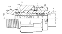
図2に示すように、この継手は概略的に見て、略円筒状の継手本体11と、この継手本体11の内部に装着され、かつ、樹脂管Pの端部内周面に嵌入される内筒12と、前記継手本体11の先端部に螺合されたナット15によって所定位置に把持され、かつ、挿入された樹脂管Pの抜け止めを行うための抜け止めリング16とによって構成されている。
Hereinafter, an embodiment in which the present invention is embodied in a joint that connects ends of resin pipes in a water supply / hot water supply piping system will be described with reference to the drawings.
As shown in FIG. 2, this joint is schematically seen as a substantially cylindrical joint
前記継手本体11の基端部(図1の左端部)の外周面には、雄ねじ部11aが螺刻され、図示しない水道配管などの管体に螺合可能になっている。継手本体11の基端部内周面には該基端部の内径よりも先端側(図1の右端側)の内径が大きくなる段差状に形成されており、その段差部分が前記内筒12の基端面12aを当接する当接面11bとなっている。又、この当接面11bよりも先端側の継手本体11の嵌入孔11cの内径は、前記内筒12の基端部外周面12bの外径よりも若干大きくなるように形成され、嵌入孔11cと内筒12の外周面12bの間に僅かな隙間Gが形成されている。
A
前記内筒12の基端部外周面12bには周方向に環状の収容溝12cが形成され、この収容溝12cにはシールリング13が嵌入され、前記嵌入孔11cの内周面に接触され、前記隙間Gのシール性が常に確保されるようになっている。前記嵌入孔11cには周方向に環状の第1係合溝11dが形成され、この第1係合溝11dと対応するように、前記基端部外周面12bには同じく周方向に環状の第2係合溝12dが形成されている。前記第1係合溝11d及び第2係合溝12dには連結リングとしてのCリング14が嵌入されている。前記嵌入孔11cの先端縁(図1の右側端)には、該先端縁から離隔するほど大径となるようにテーパ状の案内斜面11eが形成され、前記継手本体11への内筒12の装着時に、前記Cリング14を縮径しつつ前記第1係合溝11d側に案内するようになっている。
An
前記継手本体11に対する内筒12の連結作業は、次のようにして行われる。最初に、継手本体11に対し、内筒12を挿入する以前に、図4において、前記内筒12の第2係合溝12dにCリング14を係合した状態で、継手本体11の内部に内筒12を挿入し、前記案内斜面11eによって前記Cリング14を縮径方向に弾性変形させる。前記内筒12の基端面12aが前記当接面11bに当接されると、前記第1係合溝11dの位置に縮径されたCリング14が移動されるので、該Cリング14がその弾性復元力により拡径され、Cリング14の内周部が図1及び図5に示すように前記第2係合溝12dに係合されたままCリング14の外周部が第1係合溝11dに係合され、この結果、前記継手本体11に対し内筒12が回転可能に、かつ、揺動可能に連結される。
The connecting operation of the
前記継手本体11の内周面には、前記案内斜面11eの先端縁に連続するように樹脂管Pの収容孔11fが形成され、この収容孔11fの先端縁に連続するように先端側ほど大径となるテーパ面11gが形成され、このテーパ面11gの先端縁には、段差状の当接部11hが形成され、この当接部11hの先端側には、雌ねじ部11iが形成されている。前記雌ねじ部11iには、前記ナット15の外周面に形成された雄ねじ部15aが螺合され、前記当接部11hと、ナット15の内端面15bとの間には、一対の抜け止めリング16が介在され、両抜け止めリング16の間には、スペーサ17が介在されている。前記抜け止めリング16は半径方向内側に、かつ、継手本体11の内側に向かって傾斜する複数の爪部16aを備えている。この爪部16aは例えば10〜20箇所に等ピッチで形成されている。
A housing hole 11f of the resin pipe P is formed on the inner peripheral surface of the
前記内筒12の基端部外周面12bの先端縁には、樹脂管Pの端面を当接する当接面12eが形成され、この当接面12eに連続して樹脂管Pの端部内周面に嵌入される円筒状の外周面12fが形成されている。この外周面12fには周方向に環状の収容溝12g,12hが形成され、各溝には樹脂管Pの内周面に接触されるシールリング18,19が収容されている。
An
前記継手本体11の前記収容孔11f、ナット15の内周面15c及び抜け止めリング16の爪部16aと、前記内筒12の外周面12f及び前記シールリング18,19との間には、樹脂管Pを挿入する挿入空間20が形成されている。前記シールリング18,19によって、樹脂管Pの内周面と内筒12の外周面12fとの間のシール性を保持するようになっている。図1に示すように前記シールリング18,19は前記抜け止めリング16の爪部16aの先端部を基準として内筒12の先端側に配設されている。
Between the accommodation hole 11f of the
次に、前記継手の挿入空間20に対し、樹脂管Pを挿入する動作について説明する。最初に、図1の継手の挿入空間20に対して樹脂管Pの端部を挿入する。樹脂管Pの内周面によって、前記シールリング19の外周面が縮径方向に押圧され、次に、シールリング18の外周面が押圧され、さらに、樹脂管Pの端部外周面が抜け止めリング16の爪部16aを拡径方向に弾性変形させて移動され、樹脂管Pの端面が内筒12の当接面12eに当接すると、継手に対する樹脂管Pの連結動作が完了する。図2に示すように、継手に樹脂管Pが連結された状態では、樹脂管Pに通常の引き抜き方向の外力が作用した場合に、図6に実線で示すように抜け止めリング16の爪部16aが樹脂管Pの外周面に食い込んで、引き抜きが阻止される。
Next, the operation of inserting the resin pipe P into the
次に、この発明の要部構成について説明する。
前記内筒12の外周面12fには前記抜け止めリング16,16の爪部16a,16aと対応するように、かつ周方向に凹部としての環状の逃げ溝12iが形成されている。この逃げ溝12iの深さ寸法は、0.1〜1.0mmの範囲に設定されている。内筒12の逃げ溝12iによって樹脂管Pが半径方向内方に弾性変形するのを許容するようにしている。前記逃げ溝12iの軸方向の両側面は例えば60°に面取り加工されている。
Next, the configuration of the main part of the present invention will be described.
An annular relief groove 12i is formed on the outer
本実施形態によって得られる作用効果について、以下に記載する。
(1)前記実施形態では、前記内筒12の外周面12fに対し前記抜け止めリング16の爪部16aの先端と対応するように逃げ溝12iを形成したので、継手に対し樹脂管Pを連結した図2に示す状態において、樹脂管Pに通常の引き抜き方向の外力が作用した場合に、図6に実線で示すように抜け止めリング16の爪部16aの先端縁が樹脂管Pの外周面に食い込んで引き抜きが阻止される。そして、樹脂管Pに過大な引き抜き方向の外力が作用した場合に、図6に鎖線で示すように爪部16aによって樹脂管Pが逃げ溝12i側に弾性変形されて逃げ込むことになる。従って、爪部16aによる樹脂管Pの外周面への過剰な切り込みが阻止されて、樹脂管Pの切断が防止され、耐久性を向上することができる。
The effects obtained by this embodiment will be described below.
(1) In the above embodiment, the relief groove 12i is formed on the outer
(2)前記実施形態では、継手本体11の当接面11b及び嵌入孔11cに対し、内筒12の基端面12a及び基端部外周面12bを隙間Gをもって緩く嵌入し、第1及び第2係合溝11d,12dに係合したCリング14によって継手本体11と内筒12を連結し、内筒12の内部で樹脂管Pが回動可能に、かつ図3に示すように継手本体11の中心軸線O1に対し、内筒12の中心軸線O2が傾斜する方向へ揺動可能に連結した。このため、継手の挿入空間20に樹脂管Pを挿入する際に樹脂管Pを回動させながら、しかも、揺動させながら挿入することができ、挿入作業を円滑に行うことができる。
(2) In the above embodiment, the
又、継手に樹脂管Pを連結した使用状態において、樹脂管Pの内部に水撃によって樹脂管Pが過大な外力を受けた場合に、内筒12に対する樹脂管Pの連結状態が安定して保持されるので、シールリング18,19と樹脂管Pの内周面との接触状態を適正に保持して、シール性を安定して確保することができる。
Further, when the resin pipe P is connected to the joint and the resin pipe P receives an excessive external force due to water hammer inside the resin pipe P, the connection state of the resin pipe P to the
(3)前記実施形態では、内筒12の逃げ溝12iを、0.1〜1.0mmの範囲に設定したので、内筒12の肉厚を薄くする必要がなく、従って、内筒12の剛性を確保することができる。
(3) In the above embodiment, since the relief groove 12i of the
(4)前記実施形態では、内筒12の外周面12fに装着したシールリング18,19の位置を抜け止めリング16の爪部16aの先端を基準として、それよりも外側に設定したので、爪部16aによって樹脂管Pの外周面が位置規制される前に、樹脂管Pの内周面に対するシールリング18,19の嵌入動作が終了するので、挿入空間20に樹脂管Pを挿入する作業を円滑に行うことができる。
(4) In the above embodiment, since the positions of the seal rings 18 and 19 attached to the outer
なお、前記実施形態は次のように変更して構成することもできる。
・ 図示しないが、前記継手本体11に対し、別体の内筒12を固定してもよい。又、継手本体11と内筒12を一体に形成して内筒12を継手本体11から分離不能な構成としてもよい。
In addition, the said embodiment can also be changed and comprised as follows.
Although not shown, a separate
・ 図示しないが、前記シールリング18,19のいずれか一方を省略してもよい。
・ 図示しないが、継手本体11に対して内筒12を回動不能に連結し、継手本体11に対し、抜け止めリング16を回動不能に収容すると共に、抜け止めリング16の爪部16aの個数を例えば3〜5個に少なくし、各爪部16aと対応する内筒12の外周面に樹脂管Pの弾性変形を許容する凹部を形成してもよい。
Although not shown, either one of the seal rings 18 and 19 may be omitted.
Although not shown, the
・ 図示しないが、連結リングとしてのCリング14に代えて、無端環状のリングの外周面に弾性変形可能な係止爪を設けて、この係止爪を前記第1係合溝11dに係止することにより継手本体11と内筒12の連結を行うようにしてもよい。
Although not shown, instead of the
G…隙間、P…樹脂管、O1,O2…中心軸線、11…継手本体、11b,12e…当接面、11c…嵌入孔、11d…第1係合溝、12…内筒、12a…基端面、12b…基端部外周面、12c,12g,12h…収容溝、12d…第2係合溝、12f…外周面、12i…凹部としての逃げ溝、16…抜け止めリング、16a…爪部。 G ... Gap, P ... Resin pipe, O1, O2 ... Center axis, 11 ... Joint body, 11b, 12e ... Abutment surface, 11c ... Insertion hole, 11d ... First engagement groove, 12 ... Inner cylinder, 12a ... Base End surface, 12b ... Outer peripheral surface of base end portion, 12c, 12g, 12h ... Housing groove, 12d ... Second engaging groove, 12f ... Outer peripheral surface, 12i ... Relief groove as recess, 16 ... Retaining ring, 16a ... Claw .
Claims (5)
前記内筒を前記継手本体と別体に形成し、前記内筒の外周面に対し、前記樹脂管が前記継手本体に挿入された際に弾性変形された前記抜け止めリングの爪部の先端と対応する位置に前記樹脂管が前記内筒の径方向内側へ弾性変形するのを許容する凹部を設け、
前記継手本体に対し前記内筒を継手本体の中心軸線の周りで回動可能に、かつ該中心軸線に対し前記内筒の中心軸線が傾斜する方向の揺動可能に連結したことを特徴とする継手。 An inner cylinder is provided in a joint body that can be connected by inserting an end portion of the resin pipe, and the inner cylinder is fitted into an end portion of the resin pipe that is inserted into the joint body. In the joint provided with a retaining ring having a claw portion for preventing the resin tube from coming out,
The inner cylinder is formed separately from the joint body, and the claw part of the retaining ring is elastically deformed when the resin tube is inserted into the joint body with respect to the outer peripheral surface of the inner cylinder. A recess is provided at a corresponding position to allow the resin tube to be elastically deformed radially inward of the inner cylinder ,
The inner cylinder is connected to the joint main body so as to be rotatable around a central axis of the joint main body and to be swingable in a direction in which the central axis of the inner cylinder is inclined with respect to the central axis. Fittings.
前記内筒を前記継手本体と別体に形成し、前記内筒の外周面に対し、前記樹脂管が前記継手本体に挿入された際に弾性変形された前記抜け止めリングの爪部の先端と対応する位置に前記樹脂管が前記内筒の径方向内側へ弾性変形するのを許容する凹部を設け、
前記継手本体の内周面には、前記内筒の基端面を当接する当接面が形成され、該当接面に近接して前記継手本体の内周面には前記内筒の基端部外周面を所定の隙間をもって緩く嵌入する嵌入孔が形成され、該嵌入孔の内周面には周方向に沿って環状の第1係合溝が形成され、前記内筒の基端部外周面には前記第1係合溝と対応するように第2係合溝が形成され、前記第1及び第2係合溝内には連結リングが嵌入され、該連結リングによって、継手本体内で前記内筒が回動可能に、かつ揺動可能に連結されていることを特徴とする継手。 An inner cylinder is provided in a joint body that can be connected by inserting an end portion of the resin pipe, and the inner cylinder is fitted into an end portion of the resin pipe that is inserted into the joint body. In the joint provided with a retaining ring having a claw portion for preventing the resin tube from coming out,
The inner cylinder is formed separately from the joint body, and the claw part of the retaining ring is elastically deformed when the resin tube is inserted into the joint body with respect to the outer peripheral surface of the inner cylinder. A recess is provided at a corresponding position to allow the resin tube to be elastically deformed radially inward of the inner cylinder ,
A contact surface that contacts the base end surface of the inner cylinder is formed on the inner peripheral surface of the joint body, and an outer periphery of the base end portion of the inner cylinder is formed on the inner peripheral surface of the joint body in the vicinity of the contact surface. An insertion hole for loosely fitting the surface with a predetermined gap is formed, and an annular first engagement groove is formed along the circumferential direction on the inner peripheral surface of the insertion hole, and the base end portion outer peripheral surface of the inner cylinder is formed. Is formed with a second engagement groove corresponding to the first engagement groove, and a connection ring is fitted into the first and second engagement grooves. A joint characterized in that the tubes are connected so as to be rotatable and swingable .
Priority Applications (1)
| Application Number | Priority Date | Filing Date | Title |
|---|---|---|---|
| JP2005225825A JP4636963B2 (en) | 2005-08-03 | 2005-08-03 | Fitting |
Applications Claiming Priority (1)
| Application Number | Priority Date | Filing Date | Title |
|---|---|---|---|
| JP2005225825A JP4636963B2 (en) | 2005-08-03 | 2005-08-03 | Fitting |
Publications (2)
| Publication Number | Publication Date |
|---|---|
| JP2007040431A JP2007040431A (en) | 2007-02-15 |
| JP4636963B2 true JP4636963B2 (en) | 2011-02-23 |
Family
ID=37798610
Family Applications (1)
| Application Number | Title | Priority Date | Filing Date |
|---|---|---|---|
| JP2005225825A Active JP4636963B2 (en) | 2005-08-03 | 2005-08-03 | Fitting |
Country Status (1)
| Country | Link |
|---|---|
| JP (1) | JP4636963B2 (en) |
Families Citing this family (6)
| Publication number | Priority date | Publication date | Assignee | Title |
|---|---|---|---|---|
| WO2008139932A1 (en) * | 2007-05-10 | 2008-11-20 | Nix, Inc. | Structure for connection between piping and connection receiving body |
| JP2009103169A (en) * | 2007-10-22 | 2009-05-14 | Onda Seisakusho Seki Kojo:Kk | Joint |
| JP4737178B2 (en) * | 2007-11-01 | 2011-07-27 | ダイキン工業株式会社 | Pipe connection structure, valve, pipe joint and refrigeration equipment |
| JP2009115192A (en) * | 2007-11-06 | 2009-05-28 | Daikin Ind Ltd | Pipe connection structure, valve, pipe joint, and freezer |
| JP5322679B2 (en) * | 2008-06-26 | 2013-10-23 | 株式会社オンダ製作所 | Insert member and joint used for joint |
| JP6071445B2 (en) * | 2012-11-08 | 2017-02-01 | 株式会社ブリヂストン | Piping joint |
Citations (4)
| Publication number | Priority date | Publication date | Assignee | Title |
|---|---|---|---|---|
| JP2002031282A (en) * | 2000-07-11 | 2002-01-31 | Higashio Mech Co Ltd | Pipe joint |
| JP2003028373A (en) * | 2001-07-17 | 2003-01-29 | Hajime Inoue | Pipe insert joint |
| JP2003042370A (en) * | 2001-07-25 | 2003-02-13 | Onda Seisakusho:Kk | Joint |
| JP2006029355A (en) * | 2004-07-12 | 2006-02-02 | Higashio Mech Co Ltd | Pipe joint |
-
2005
- 2005-08-03 JP JP2005225825A patent/JP4636963B2/en active Active
Patent Citations (4)
| Publication number | Priority date | Publication date | Assignee | Title |
|---|---|---|---|---|
| JP2002031282A (en) * | 2000-07-11 | 2002-01-31 | Higashio Mech Co Ltd | Pipe joint |
| JP2003028373A (en) * | 2001-07-17 | 2003-01-29 | Hajime Inoue | Pipe insert joint |
| JP2003042370A (en) * | 2001-07-25 | 2003-02-13 | Onda Seisakusho:Kk | Joint |
| JP2006029355A (en) * | 2004-07-12 | 2006-02-02 | Higashio Mech Co Ltd | Pipe joint |
Also Published As
| Publication number | Publication date |
|---|---|
| JP2007040431A (en) | 2007-02-15 |
Similar Documents
| Publication | Publication Date | Title |
|---|---|---|
| JP6948372B2 (en) | Pipe fitting | |
| JP4636963B2 (en) | Fitting | |
| WO2015029815A1 (en) | Tube joint | |
| WO2012128152A1 (en) | Pipe joint | |
| JP2007040432A (en) | Joint | |
| JP2007255685A (en) | Pipe joint | |
| JP2009103169A (en) | Joint | |
| JP2006170379A (en) | Joint | |
| JP6078857B2 (en) | Pipe fitting | |
| JP2009144740A (en) | Joint having adapter | |
| JP5982184B2 (en) | Telescopic flexible joint | |
| US10794517B2 (en) | System, method and apparatus for expansion coupling for pipes with sheathed grooves | |
| JP5849261B2 (en) | Pipe fitting | |
| JP2006183764A (en) | Joint | |
| JP2009092165A (en) | Connector and connection device of concrete member using the same | |
| JP2005330983A (en) | Mechanical pipe fitting | |
| JP4066397B2 (en) | Tube connection method | |
| US6871882B2 (en) | Ball-and-socket fluid coupling with primary and secondary retainer structures | |
| JP6215585B2 (en) | Pipe fitting | |
| WO2011001376A1 (en) | Pipe coupling | |
| JP2009063019A (en) | Header | |
| JP4828381B2 (en) | Fitting | |
| JP2009287646A (en) | Pipe joint | |
| JP2009133448A (en) | Pipe fitting | |
| JP5275839B2 (en) | Pipe fitting |
Legal Events
| Date | Code | Title | Description |
|---|---|---|---|
| A621 | Written request for application examination |
Free format text: JAPANESE INTERMEDIATE CODE: A621 Effective date: 20080516 |
|
| A711 | Notification of change in applicant |
Free format text: JAPANESE INTERMEDIATE CODE: A711 Effective date: 20091005 |
|
| A977 | Report on retrieval |
Free format text: JAPANESE INTERMEDIATE CODE: A971007 Effective date: 20100803 |
|
| A131 | Notification of reasons for refusal |
Free format text: JAPANESE INTERMEDIATE CODE: A131 Effective date: 20100824 |
|
| A521 | Request for written amendment filed |
Free format text: JAPANESE INTERMEDIATE CODE: A523 Effective date: 20101022 |
|
| TRDD | Decision of grant or rejection written | ||
| A01 | Written decision to grant a patent or to grant a registration (utility model) |
Free format text: JAPANESE INTERMEDIATE CODE: A01 Effective date: 20101116 |
|
| A01 | Written decision to grant a patent or to grant a registration (utility model) |
Free format text: JAPANESE INTERMEDIATE CODE: A01 |
|
| A61 | First payment of annual fees (during grant procedure) |
Free format text: JAPANESE INTERMEDIATE CODE: A61 Effective date: 20101122 |
|
| FPAY | Renewal fee payment (event date is renewal date of database) |
Free format text: PAYMENT UNTIL: 20131203 Year of fee payment: 3 |
|
| R150 | Certificate of patent or registration of utility model |
Free format text: JAPANESE INTERMEDIATE CODE: R150 Ref document number: 4636963 Country of ref document: JP Free format text: JAPANESE INTERMEDIATE CODE: R150 |
|
| FPAY | Renewal fee payment (event date is renewal date of database) |
Free format text: PAYMENT UNTIL: 20131203 Year of fee payment: 3 |
|
| S531 | Written request for registration of change of domicile |
Free format text: JAPANESE INTERMEDIATE CODE: R313531 |
|
| FPAY | Renewal fee payment (event date is renewal date of database) |
Free format text: PAYMENT UNTIL: 20131203 Year of fee payment: 3 |
|
| R350 | Written notification of registration of transfer |
Free format text: JAPANESE INTERMEDIATE CODE: R350 |
|
| R250 | Receipt of annual fees |
Free format text: JAPANESE INTERMEDIATE CODE: R250 |
|
| R250 | Receipt of annual fees |
Free format text: JAPANESE INTERMEDIATE CODE: R250 |
|
| R250 | Receipt of annual fees |
Free format text: JAPANESE INTERMEDIATE CODE: R250 |
|
| R250 | Receipt of annual fees |
Free format text: JAPANESE INTERMEDIATE CODE: R250 |
|
| R250 | Receipt of annual fees |
Free format text: JAPANESE INTERMEDIATE CODE: R250 |
|
| R250 | Receipt of annual fees |
Free format text: JAPANESE INTERMEDIATE CODE: R250 |
|
| R250 | Receipt of annual fees |
Free format text: JAPANESE INTERMEDIATE CODE: R250 |
|
| R250 | Receipt of annual fees |
Free format text: JAPANESE INTERMEDIATE CODE: R250 |
|
| R250 | Receipt of annual fees |
Free format text: JAPANESE INTERMEDIATE CODE: R250 |