JP5980809B2 - Homogenizing valve - Google Patents
Homogenizing valve Download PDFInfo
- Publication number
- JP5980809B2 JP5980809B2 JP2013545318A JP2013545318A JP5980809B2 JP 5980809 B2 JP5980809 B2 JP 5980809B2 JP 2013545318 A JP2013545318 A JP 2013545318A JP 2013545318 A JP2013545318 A JP 2013545318A JP 5980809 B2 JP5980809 B2 JP 5980809B2
- Authority
- JP
- Japan
- Prior art keywords
- valve
- homogenization
- cone
- gap
- gaps
- Prior art date
- Legal status (The legal status is an assumption and is not a legal conclusion. Google has not performed a legal analysis and makes no representation as to the accuracy of the status listed.)
- Expired - Fee Related
Links
Images


Classifications
-
- B—PERFORMING OPERATIONS; TRANSPORTING
- B01—PHYSICAL OR CHEMICAL PROCESSES OR APPARATUS IN GENERAL
- B01F—MIXING, e.g. DISSOLVING, EMULSIFYING OR DISPERSING
- B01F25/00—Flow mixers; Mixers for falling materials, e.g. solid particles
- B01F25/40—Static mixers
- B01F25/44—Mixers in which the components are pressed through slits
-
- A—HUMAN NECESSITIES
- A01—AGRICULTURE; FORESTRY; ANIMAL HUSBANDRY; HUNTING; TRAPPING; FISHING
- A01J—MANUFACTURE OF DAIRY PRODUCTS
- A01J11/00—Apparatus for treating milk
- A01J11/16—Homogenising milk
-
- B—PERFORMING OPERATIONS; TRANSPORTING
- B01—PHYSICAL OR CHEMICAL PROCESSES OR APPARATUS IN GENERAL
- B01F—MIXING, e.g. DISSOLVING, EMULSIFYING OR DISPERSING
- B01F23/00—Mixing according to the phases to be mixed, e.g. dispersing or emulsifying
- B01F23/40—Mixing liquids with liquids; Emulsifying
- B01F23/41—Emulsifying
-
- B—PERFORMING OPERATIONS; TRANSPORTING
- B01—PHYSICAL OR CHEMICAL PROCESSES OR APPARATUS IN GENERAL
- B01F—MIXING, e.g. DISSOLVING, EMULSIFYING OR DISPERSING
- B01F25/00—Flow mixers; Mixers for falling materials, e.g. solid particles
- B01F25/40—Static mixers
- B01F25/44—Mixers in which the components are pressed through slits
- B01F25/441—Mixers in which the components are pressed through slits characterised by the configuration of the surfaces forming the slits
- B01F25/4412—Mixers in which the components are pressed through slits characterised by the configuration of the surfaces forming the slits the slits being formed between opposed planar surfaces, e.g. pushed again each other by springs
- B01F25/44121—Mixers in which the components are pressed through slits characterised by the configuration of the surfaces forming the slits the slits being formed between opposed planar surfaces, e.g. pushed again each other by springs with a plurality of parallel slits, e.g. formed between stacked plates
-
- B—PERFORMING OPERATIONS; TRANSPORTING
- B01—PHYSICAL OR CHEMICAL PROCESSES OR APPARATUS IN GENERAL
- B01F—MIXING, e.g. DISSOLVING, EMULSIFYING OR DISPERSING
- B01F25/00—Flow mixers; Mixers for falling materials, e.g. solid particles
- B01F25/40—Static mixers
- B01F25/44—Mixers in which the components are pressed through slits
- B01F25/441—Mixers in which the components are pressed through slits characterised by the configuration of the surfaces forming the slits
- B01F25/4413—Mixers in which the components are pressed through slits characterised by the configuration of the surfaces forming the slits the slits being formed between opposed conical or cylindrical surfaces
-
- B—PERFORMING OPERATIONS; TRANSPORTING
- B01—PHYSICAL OR CHEMICAL PROCESSES OR APPARATUS IN GENERAL
- B01F—MIXING, e.g. DISSOLVING, EMULSIFYING OR DISPERSING
- B01F25/00—Flow mixers; Mixers for falling materials, e.g. solid particles
- B01F25/40—Static mixers
- B01F25/44—Mixers in which the components are pressed through slits
- B01F25/442—Mixers in which the components are pressed through slits characterised by the relative position of the surfaces during operation
- B01F25/4422—Mixers in which the components are pressed through slits characterised by the relative position of the surfaces during operation the surfaces being maintained in a fixed but adjustable position, spaced from each other, therefore allowing the slit spacing to be varied
-
- B—PERFORMING OPERATIONS; TRANSPORTING
- B01—PHYSICAL OR CHEMICAL PROCESSES OR APPARATUS IN GENERAL
- B01F—MIXING, e.g. DISSOLVING, EMULSIFYING OR DISPERSING
- B01F25/00—Flow mixers; Mixers for falling materials, e.g. solid particles
- B01F25/40—Static mixers
- B01F25/44—Mixers in which the components are pressed through slits
- B01F25/442—Mixers in which the components are pressed through slits characterised by the relative position of the surfaces during operation
- B01F25/4423—Mixers in which the components are pressed through slits characterised by the relative position of the surfaces during operation the surfaces being part of a valve construction, formed by opposed members in contact, e.g. automatic positioning caused by spring pressure
-
- B—PERFORMING OPERATIONS; TRANSPORTING
- B01—PHYSICAL OR CHEMICAL PROCESSES OR APPARATUS IN GENERAL
- B01F—MIXING, e.g. DISSOLVING, EMULSIFYING OR DISPERSING
- B01F25/00—Flow mixers; Mixers for falling materials, e.g. solid particles
- B01F25/40—Static mixers
- B01F25/46—Homogenising or emulsifying nozzles
-
- B—PERFORMING OPERATIONS; TRANSPORTING
- B01—PHYSICAL OR CHEMICAL PROCESSES OR APPARATUS IN GENERAL
- B01F—MIXING, e.g. DISSOLVING, EMULSIFYING OR DISPERSING
- B01F2101/00—Mixing characterised by the nature of the mixed materials or by the application field
- B01F2101/06—Mixing of food ingredients
- B01F2101/07—Mixing ingredients into milk or cream, e.g. aerating
-
- B—PERFORMING OPERATIONS; TRANSPORTING
- B01—PHYSICAL OR CHEMICAL PROCESSES OR APPARATUS IN GENERAL
- B01F—MIXING, e.g. DISSOLVING, EMULSIFYING OR DISPERSING
- B01F2215/00—Auxiliary or complementary information in relation with mixing
- B01F2215/04—Technical information in relation with mixing
- B01F2215/0413—Numerical information
- B01F2215/0418—Geometrical information
- B01F2215/0431—Numerical size values, e.g. diameter of a hole or conduit, area, volume, length, width, or ratios thereof
-
- B—PERFORMING OPERATIONS; TRANSPORTING
- B01—PHYSICAL OR CHEMICAL PROCESSES OR APPARATUS IN GENERAL
- B01F—MIXING, e.g. DISSOLVING, EMULSIFYING OR DISPERSING
- B01F2215/00—Auxiliary or complementary information in relation with mixing
- B01F2215/04—Technical information in relation with mixing
- B01F2215/0413—Numerical information
- B01F2215/0436—Operational information
- B01F2215/0468—Numerical pressure values
-
- B—PERFORMING OPERATIONS; TRANSPORTING
- B01—PHYSICAL OR CHEMICAL PROCESSES OR APPARATUS IN GENERAL
- B01F—MIXING, e.g. DISSOLVING, EMULSIFYING OR DISPERSING
- B01F2215/00—Auxiliary or complementary information in relation with mixing
- B01F2215/04—Technical information in relation with mixing
- B01F2215/0413—Numerical information
- B01F2215/0436—Operational information
- B01F2215/0472—Numerical temperature values
-
- B—PERFORMING OPERATIONS; TRANSPORTING
- B01—PHYSICAL OR CHEMICAL PROCESSES OR APPARATUS IN GENERAL
- B01F—MIXING, e.g. DISSOLVING, EMULSIFYING OR DISPERSING
- B01F23/00—Mixing according to the phases to be mixed, e.g. dispersing or emulsifying
- B01F23/40—Mixing liquids with liquids; Emulsifying
- B01F23/41—Emulsifying
- B01F23/413—Homogenising a raw emulsion or making monodisperse or fine emulsions
Landscapes
- Chemical & Material Sciences (AREA)
- Chemical Kinetics & Catalysis (AREA)
- Dispersion Chemistry (AREA)
- Life Sciences & Earth Sciences (AREA)
- Animal Husbandry (AREA)
- Environmental Sciences (AREA)
- Lift Valve (AREA)
Description
本発明は、加圧された、可動式の2つ以上のバルブコーンと、2つ以上のバルブシートと、バルブコーンとバルブシートとを取り囲んだバルブハウジングと、を具備し、バルブコーンとバルブシートとは、それらの間に狭窄部が形成されて、狭窄部が2つ以上の均質化ギャップを構成するように配列され、バルブコーンはバルブハウジング内の中心に設けられたネジロッドにネジ結合され、バルブコーンはバルブコーンがネジロッドと一体に調節されるように配列された均質化バルブに関する。 The present invention comprises a pressurized, movable two or more valve cones, two or more valve seats, and a valve housing surrounding the valve cone and the valve seat. Means that a constriction is formed between them, the constriction is arranged to form two or more homogenization gaps, and the valve cone is screwed to a screw rod provided in the center of the valve housing; The valve cone relates to a homogenizing valve arranged so that the valve cone is adjusted integrally with the threaded rod.
均質化は長く使用されている産業プロセスであり、このプロセスは、例えば牛乳のような脂肪乳剤において、最も大きい脂肪球をより小さい脂肪球へと分割し、これによって脂肪乳剤を安定化させることを目的としている。例えば牛乳に関しては、このことはクリーム化が防止されることを意味しており、全消費者向けの牛乳の大部分が今日では均質化されている。 Homogenization is an industrial process that has been used for a long time, and this process, for example, in fat emulsions like milk, divides the largest fat globules into smaller fat globules, thereby stabilizing the fat emulsion. It is aimed. For milk, for example, this means that creaming is prevented and the majority of milk for all consumers is now homogenized.
均質化は通常は機械的処理によって実行され、高い入力圧力を有する脂肪乳剤は非常に狭いギャップを高速で通過させられ、そこで、脂肪乳剤の脂肪球は高速において生じた乱流および液体内で破裂したキャビテーション気泡によって破壊される。処理は非常に短時間の間に生じ、この時間中に発生することは、通過する際の脂肪乳剤の速度が、圧力の減少のために増加し、このことが液体を沸騰させることである。 Homogenization is usually carried out by mechanical processing, fat emulsions with high input pressure are passed through very narrow gaps at high speeds, where fat globules of fat emulsions burst in the turbulent flow and liquid generated at high speeds. Destroyed by cavitation bubbles. Processing occurs in a very short period of time, and what happens during this time is that the speed of the fat emulsion as it passes increases due to a decrease in pressure, which causes the liquid to boil.
均質化器は基本的に高い圧力を発生する大型のピストンポンプと、その内部において実際の均質化が生じる対抗圧力デバイスと、から成る。対抗圧力デバイス、または言い換えると均質化バルブは、加圧された弾性バルブコーン、バルブシート、および摩耗リング、ならびにバルブコーンとバルブシートとを取り囲んだバルブハウジングから成る。バルブコーンとバルブシートとは通常は回転対称であり、均質化ギャップを構成する径方向狭窄部がこれらの2つの部品の間に生じるように配列されている。ギャップの高さ、幅、および長さは、均質化が生じる容積を決定している。この容積は、効果的な均質化を得るために十分に小さくなければならない。ギャップ高さは、均質化される液体により高い圧力がかかっている場合には減少され、それと同時に、より大量の流れはギャップ高さが増加したことを意味している。 The homogenizer basically consists of a large piston pump that generates high pressure and a counter pressure device in which the actual homogenization takes place. The counter pressure device, or in other words the homogenization valve, consists of a pressurized elastic valve cone, a valve seat and a wear ring, and a valve housing surrounding the valve cone and valve seat. The valve cone and the valve seat are usually rotationally symmetric and are arranged so that a radial constriction forming a homogenization gap occurs between these two parts. The height, width, and length of the gap determine the volume at which homogenization occurs. This volume must be small enough to obtain effective homogenization. The gap height is reduced when higher pressure is applied to the liquid to be homogenized, and at the same time a larger flow means that the gap height has increased.
特に殺菌された牛乳の均質化においては、超高温処理された牛乳と比較して、より低い圧力が採用され、それと同時に流量を増加させることが望まれている。このことは、このより低い圧力および増加した流れにおいて良好な均質化を得るために、ギャップ高さが減少するように、均質化バルブがより大きく形成される必要があることを意味している。しかしながら、良好に機能している既存の均質化バルブの大型化は、実際には常にとりわけ良好に作用するものではないことが示されている。獲得した加圧される面が大きくなればなるほど、発生する力は大きくなり、均質化バルブはより大型化されなければならない。それと同時に、そのような均質化バルブのコストは何倍にも上昇する。 Especially in the homogenization of sterilized milk, it is desired to employ a lower pressure and at the same time increase the flow rate compared to milk that has been processed at ultra high temperatures. This means that in order to obtain good homogenization at this lower pressure and increased flow, the homogenization valve needs to be made larger so that the gap height is reduced. However, it has been shown that the increase in size of existing homogenizing valves that perform well does not always work particularly well in practice. The larger the acquired surface to be pressurized, the greater the force generated and the homogenization valve must be made larger. At the same time, the cost of such a homogenizing valve increases many times.
問題を解決する別の方法は、特許文献1に示されたように、複数の均質化ギャップを並列に接続することである。この方法において、ギャップ長さの延長、したがってギャップ高さの減少が得られる。しかしながら、並列接続された均質化ギャップを備えたこのタイプの均質化バルブは、実質的には固定されたギャップ高さを有する。変化することなく、その均質化バルブは1つのみの流れおよび1つのみの均質化圧力を許容している。そのバルブは、均質化の成果に悪影響を与える、不均一な且つ制御不能な様式において均質化ギャップが摩耗するという欠点も有する。 Another way to solve the problem is to connect a plurality of homogenization gaps in parallel, as shown in US Pat. In this way, an extension of the gap length and thus a reduction of the gap height is obtained. However, this type of homogenization valve with parallelized homogenization gaps has a substantially fixed gap height. Without change, the homogenization valve allows only one flow and only one homogenization pressure. The valve also has the disadvantage that the homogenization gap wears in a non-uniform and uncontrollable manner that adversely affects the homogenization results.
特許文献2は、ネジロッドがバルブハウジング内の中心に配置されることによって、およびバルブコーンがネジロッドと一体で調節可能であることによって、並列接続された複数の均質化ギャップがどのように配列されることが可能であるかを開示している。この均質化バルブは異なった流れに関して調節されることが可能である。
本発明の1つの目的は、ギャップ長さに関して良好な調節性を提供する均質化バルブを得ることであり、それと同時により低いギャップ高さが得られることである。均質化ギャップは小さいギャップ高さを有し、高い容量および低い均質化圧力が兼ね備えられる。 One object of the present invention is to obtain a homogenizing valve that provides good adjustability with respect to the gap length, while at the same time a lower gap height is obtained. The homogenization gap has a small gap height and combines high capacity and low homogenization pressure.
本発明のさらなる目的は、圧力および流れが変化した場合に、ギャップ高さが調節されることが可能であることである。 A further object of the present invention is that the gap height can be adjusted as pressure and flow change.
本発明の別の目的は、均質化バルブをより短くすることによって、均質化バルブがより安価に製造できるようになることである。 Another object of the invention is to make the homogenization valve cheaper by making the homogenization valve shorter.
さらに、本発明の別の目的は、均質化バルブが効果的な洗浄を可能とし、その一方で、食品の取り扱いの厳しい要求を満足することである。 Furthermore, another object of the present invention is that the homogenization valve enables effective cleaning while satisfying the strict requirements of food handling.
これらのおよび他の目的は、導入部に記載されたタイプの均質化バルブが、各バルブシートとバルブコーンとの間に、径方向に配列された均質化ギャップおよび軸方向に配列された均質化ギャップが形成されている特徴を与えられているという事実によって、本発明により達成されている。 These and other objectives are that homogenization valves of the type described in the introduction are arranged between each valve seat and the valve cone in a radially arranged homogenization gap and in an axial arrangement. This is achieved by the present invention by the fact that the gap is given the characteristic that it is formed.
本発明の好適な実施形態は、従属請求項から明らかとなる特徴をさらに与えられている。 Preferred embodiments of the invention are further given the features that are apparent from the dependent claims.
本発明の好適な実施形態は、添付図を参照するとともに、ここにより詳細に記載されている。 Preferred embodiments of the present invention will now be described in more detail with reference to the accompanying drawings.
図は、本発明の理解のために重要なバルブの詳細および均質化器内における均質化バルブの位置のみを示しており、当業者に周知の詳細は省略されている。 The figure shows only the details of the valves important for understanding the invention and the position of the homogenization valve in the homogenizer, omitting details known to those skilled in the art.
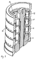
図1〜図3に示されたように、本発明による均質化バルブ1は基本的に、均質化される液体のための流入口3と流出口4とを備えたバルブハウジング2と、複数のバルブコーン5と、複数のバルブシート6と、から成る。
1-3, the
バルブコーン5とバルブシート6とは、それらの間に均質化ギャップである狭窄部が形成されるように配列されている。各バルブシート6と各バルブコーン5との間には、径方向に配列された均質化ギャップ7および軸方向に配列された均質化ギャップ8の、2つの均質化ギャップが形成されている。
The
バルブコーン5とバルブシート6との間において密封を形成するシールであるOリングが排除されたという事実は、追加の均質化ギャップ7、8が各バルブシート6とバルブコーン5とに関して個々に得られることを意味している。しかしながら、下部Oリング9はバルブハウジングに対するシールを形成するために残存している。
The fact that the O-ring, which is a seal that forms a seal between the
Oリングは大部分が排除されたという事実は、各バルブコーン5とバルブシート6とに関してより多くの均質化ギャップ7、8が得られることを意味している。したがって、均質化バルブ1はより短くされることが可能であり、従来6つの均質化ギャップの容量を有する均質化バルブ1は、6つのバルブコーン5と6つのバルブシート6とを必要とする一方で、新しい実施形態においては、均質化バルブは4つのバルブコーン5と4つのバルブシート6とのみを必要とし、7つの均質化ギャップ7、8に相当する容量を与える。
The fact that the O-ring is largely eliminated means that more homogenization gaps 7, 8 are obtained for each
好適な実施形態において、バルブシート6は回転対称であり、均質化される液体を通過させることが可能な開口部10を備えている。バルブシート6は1つのバルブシートが他のバルブシートの上に載置されており、バルブハウジング2に固定されている。
In a preferred embodiment, the
同様に回転対称であるバルブコーン5は、均質化バルブ1の中心に向かったネジ面11を備えている。均質化バルブ1の中心にはネジロッド12が設けられており、そのネジはバルブコーン5のネジ面11に最終的に係合する。一体にネジ結合した部分は、Oリングタイプの衛生的なシール13を利用して、バルブコーン5を通過する製品から密封される。
Similarly, the rotationally
ネジロッド12と一体にネジ結合されたバルブコーン5は、通常は油圧または空気圧ピストン14によって加圧されるが、より簡素な実施形態ではバネを介して作用する位置決めネジによって加圧されることが可能である。均質化される液体中に発生する急速な流れの変化を緩和することを可能にするために、バルブコーン5も例えばシリンダ内のオイルを手段として可動式とされている。ピストンポンプ内に自然に発生する流れの変化に対処するために、弾性が必要である。
The
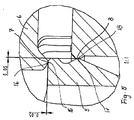
バルブコーン5とネジロッド12とはバルブハウジング2内に配置されており、バルブコーン5の径方向面15とバルブシート6の径方向面16との間には、高さhの径方向均質化ギャップ7が形成されている。均質化ギャップ7の高さは、バルブコーン5がバルブシート6に接近またはバルブシート6から離間するように移動されることによって変化した圧力および流れにともなって、変化されることが可能である。バルブコーン5がネジロッド12にネジ結合されているので、均質化バルブ1内においてすべての径方向均質化ギャップ7に関する同一の高さhを確実に得ることが可能である。
The
バルブコーン5の軸方向面17とバルブシート6の軸方向面18との間にも、均質化ギャップ8が形成されている。しかしながら、これらの軸方向均質化ギャップ8は固定されており、ネジロッド12によって調節不可能である。
A homogenization gap 8 is also formed between the
均質化バルブ1のハウジング2内には、複数のバルブコーン5と複数のバルブシート6とが配列されている。図1〜図3において、4つのバルブコーン5と4つのバルブシート6とが示されている。4つの径方向ギャップと3つの軸方向ギャップ8とから成る7つの均質化ギャップが、これによって得られている。本発明による均質化バルブ1は、所望の容量および用途に依存して、より多くのまたはより少ないバルブコーン5およびバルブシート6を収容していてもよい。バルブハウジング2を分けて製造することによって、より多い数のまたはより少ない数のバルブコーン5およびバルブシート6を容易に組み立てることが可能となる。
A plurality of
通常は牛乳である、均質化される液体は均質化器内に導入され、そこで約10MPa〜25MPaに加圧される。牛乳は通常は0.5%〜3.5%の脂肪分を有し、55℃〜80℃の温度である。 The liquid to be homogenized, usually milk, is introduced into a homogenizer where it is pressurized to about 10-25 MPa. Milk usually has a fat content of 0.5% to 3.5% and a temperature of 55 ° C to 80 ° C.
液体は流入口3を通じて導入され、バルブコーン5内に存在する孔19を通過する。この後、液体は、均質化が生じる異なった均質化ギャップ7、8の1つを通過する。液体はその次にバルブシート内の開口部10を通じて出て行き、その後液体はチャネル20内に収集される。液体は常に最も単純な経路を進もうとするので、異なった均質化ギャップ7、8を通じた液体の比較的均一な分配が得られる。均質化の後、液体は流出口4を通じて均質化バルブ1から流出する。
The liquid is introduced through the inlet 3 and passes through the
ギャップ高さは通常は50μm〜200μmである。通過の際、0MPaに向かう非常に急速な圧力降下が得られ、それと同時に液体の速度が増加し、液体を沸騰させ始める。液体が均質化ギャップ7、8を離れたとき、速度は減少し、圧力は再度上昇する。液体は沸騰を止め、液体内の蒸気の泡は破裂する。全体の処理はわずか数秒にわたって行われ、激しい処理においては、高速が乱流およびキャビテーションを引き起こし、液体内に存在する脂肪球は、より小さい粒子へと分割される。 The gap height is usually 50 μm to 200 μm. On passing, a very rapid pressure drop towards 0 MPa is obtained, at the same time the speed of the liquid increases and begins to boil the liquid. When the liquid leaves the homogenization gap 7, 8, the velocity decreases and the pressure increases again. The liquid stops boiling and the vapor bubbles in the liquid burst. The entire process takes only a few seconds, and in intense processes, high speed causes turbulence and cavitation, and fat globules present in the liquid are broken up into smaller particles.
異なった均質化ギャップ7および8の間において液体の均一な分配が得られるので、非常に良好な用途が、増加したギャップ長さから作り上げられ、本発明による均質化バルブ1を備えた均質化器は従来の均質化バルブよりも何倍も多くの流れを処理することが可能である。それと同時に、ピストンがバルブシート6に関してバルブコーン5を変位させることが可能であり、これによって径方向均質化ギャップ7の異なった高さを得ることが可能であるため、均質化バルブは製品の流れの変化に関して調節可能である。バルブコーン5はネジロッド12にネジ結合されているので、すべての径方向均質化ギャップ7は同一のギャップ高さhを有する。ネジロッド12と同様にすべてのバルブコーン5はユニットとして調節され、すべての径方向均質化ギャップ7は同一のギャップ高さhを常に有する。
Since a uniform distribution of the liquid is obtained between the different homogenization gaps 7 and 8, a very good application is built up from the increased gap length and the homogenizer with the
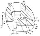
図4および図6において、均質化バルブ1はその洗浄位置において示されている。バルブコーン5への圧力は空気圧または油圧ピストンが緩和することによって解放され、次いで、その内部に均質化ギャップ7、8が通常は見られる開口部21、22を提供する。洗浄液はこれらの開口部21、22を通じて自由に通過することが可能であるので、製品と接触する均質化バルブのすべての部品は、効果的に洗浄されることが可能である。
4 and 6, the
上述の記載から明確にされたように、既存の均質化器に組み込むために使用されるが、対応した従来の均質化バルブよりも非常に大量の流れを処理することが可能な均質化バルブは、本発明を用いて実現される。それと同時に、均質化バルブは圧力および流れにおける瞬間的な変化に関して調節されることが可能である。均質化バルブの調節性は、そのバルブがこれまでに既知の均質化バルブよりも摩耗および引き裂きに関してより良好な特性を示すことも意味している。均質化バルブの長さおよび構造も、バルブの製造を比較的安価にしている。 As clarified from the above description, a homogenization valve that is used for incorporation into an existing homogenizer, but is capable of handling much larger flows than the corresponding conventional homogenization valve, This is realized using the present invention. At the same time, the homogenization valve can be adjusted for instantaneous changes in pressure and flow. The adjustability of the homogenizing valve also means that the valve exhibits better properties in terms of wear and tear than previously known homogenizing valves. The length and structure of the homogenization valve also makes the manufacture of the valve relatively inexpensive.
1 ・・・均質化バルブ
2 ・・・バルブハウジング
3 ・・・流入口
4 ・・・流出口
5 ・・・バルブコーン
6 ・・・バルブシート
7,8 ・・・均質化ギャップ
9 ・・・Oリング
10 ・・・開口部
11 ・・・ネジ面
12 ・・・ネジロッド
13 ・・・シール
14 ・・・ピストン
20 ・・・チャネル
21,22 ・・・開口部
DESCRIPTION OF
Claims (4)
前記バルブコーン(5)と前記バルブシート(6)とは、それらの間に狭窄部が形成されて、該狭窄部が2つ以上の均質化ギャップ(7)を構成するように配列され、前記バルブコーン(5)は前記バルブハウジング内の中心に設けられたネジロッドにネジ結合され、前記バルブコーンは該バルブコーンが前記ネジロッドと一体に調節されるように配列された均質化バルブ(1)において、
1つ1つの前記バルブシートとバルブコーンとの間には径方向に配列された均質化ギャップと、軸方向に配列された均質化ギャップと、が形成されており、
前記径方向に配列された均質化ギャップと前記軸方向に配列された均質化ギャップとは、互いに独立していることを特徴とする均質化バルブ(1)。 Two or more pressurized, movable valve cones (5), two or more valve seats (6), and a valve housing (2) surrounding the valve cones (5) and valve seats (6) ), And
The valve cone (5) and the valve seat (6) are arranged such that a constriction is formed between them, and the constriction forms two or more homogenization gaps (7), In the homogenization valve (1), the valve cone (5) is screwed to a threaded rod provided in the center of the valve housing, the valve cone being arranged so that the valve cone is adjusted integrally with the threaded rod. ,
A homogenization gap arranged in the radial direction and a homogenization gap arranged in the axial direction are formed between each of the valve seat and the valve cone ,
Homogenization valve (1), characterized in that said radially arranged homogenization gap and said axially arranged homogenization gap are independent of each other .
Applications Claiming Priority (3)
| Application Number | Priority Date | Filing Date | Title |
|---|---|---|---|
| SE1001213-6 | 2010-12-22 | ||
| SE1001213A SE535549C2 (en) | 2010-12-22 | 2010-12-22 | homogenizer |
| PCT/EP2011/073455 WO2012084986A1 (en) | 2010-12-22 | 2011-12-20 | Homogenizing valve |
Publications (2)
| Publication Number | Publication Date |
|---|---|
| JP2014502918A JP2014502918A (en) | 2014-02-06 |
| JP5980809B2 true JP5980809B2 (en) | 2016-08-31 |
Family
ID=45422140
Family Applications (1)
| Application Number | Title | Priority Date | Filing Date |
|---|---|---|---|
| JP2013545318A Expired - Fee Related JP5980809B2 (en) | 2010-12-22 | 2011-12-20 | Homogenizing valve |
Country Status (13)
| Country | Link |
|---|---|
| US (2) | US9199208B2 (en) |
| EP (1) | EP2654933B1 (en) |
| JP (1) | JP5980809B2 (en) |
| CN (1) | CN103260735B (en) |
| BR (1) | BR112013015411A2 (en) |
| DK (1) | DK2654933T3 (en) |
| ES (1) | ES2536532T3 (en) |
| MX (1) | MX2013006997A (en) |
| NZ (1) | NZ611795A (en) |
| PL (1) | PL2654933T3 (en) |
| PT (1) | PT2654933E (en) |
| SE (1) | SE535549C2 (en) |
| WO (1) | WO2012084986A1 (en) |
Families Citing this family (8)
| Publication number | Priority date | Publication date | Assignee | Title |
|---|---|---|---|---|
| SE531925C2 (en) * | 2008-01-29 | 2009-09-08 | Tetra Laval Holdings & Finance | homogenizer |
| SE535549C2 (en) * | 2010-12-22 | 2012-09-18 | Tetra Laval Holdings & Finance | homogenizer |
| CN103521330B (en) * | 2013-10-17 | 2016-03-02 | 广州派勒机械设备有限公司 | A kind of high-pressure nano homogenizer |
| ITPR20130081A1 (en) * | 2013-10-21 | 2015-04-22 | Gea mechanical equipment italia spa | HOMOGENIZING VALVE, IN PARTICULAR FOR APPLICATION TO FIBROUS FLUIDS |
| US10065158B2 (en) * | 2016-08-19 | 2018-09-04 | Arisdyne Systems, Inc. | Device with an inlet suction valve and discharge suction valve for homogenizaing a liquid and method of using the same |
| CN106508686B (en) * | 2016-11-09 | 2019-03-19 | 安徽永牧机械集团有限公司 | A kind of environment-friendly type teatcup and its manufacturing method |
| GB202008025D0 (en) * | 2020-05-28 | 2020-07-15 | Micropore Tech Limited | Membrane emulsification apparatus with refiner |
| DE102021004243B4 (en) | 2021-08-20 | 2023-11-30 | Gea Mechanical Equipment Italia S.P.A. | Valve and use of a valve |
Family Cites Families (30)
| Publication number | Priority date | Publication date | Assignee | Title |
|---|---|---|---|---|
| FR451028A (en) * | 1911-12-02 | 1913-04-09 | Franz Max Berberich | Method and apparatus for mixing and homogenizing liquids |
| GB191315774A (en) * | 1912-09-26 | 1914-03-05 | Wilhelm Gotthilf Schroeder | Improvements in or relating to Devices for Mixing Emulsions. |
| US1097474A (en) * | 1913-07-23 | 1914-05-19 | Wilhelm Gotthilf Schroeder | Device for mixing emulsions. |
| FR461782A (en) | 1913-08-08 | 1914-01-10 | Des Anciens Etablissements Hotchkiss Et Cie | Improvements to automatic rifles |
| US2137854A (en) * | 1937-09-04 | 1938-11-22 | Union Steam Pump Company | Apparatus for homogenizing liquids |
| US2435884A (en) * | 1945-12-18 | 1948-02-10 | Kermit B Niles | Homogenizing unit |
| BE582608A (en) * | 1958-09-15 | |||
| DE1147920B (en) * | 1959-09-01 | 1963-05-02 | Albina Ets | Device for homogenizing liquid and pulpy substances |
| US3179385A (en) * | 1961-11-17 | 1965-04-20 | Manton Gaulin Mfg Company Inc | Method and apparatus for processing fluids |
| GB1002523A (en) * | 1963-01-23 | 1965-08-25 | Ultrasonic Ltd | Improvements relating to the production of aerosols and the like |
| US3423028A (en) * | 1967-04-28 | 1969-01-21 | Du Pont | Jet fluid mixing device and process |
| US3544078A (en) * | 1967-04-28 | 1970-12-01 | Du Pont | Jet fluid mixing process |
| DE1757297C3 (en) * | 1967-04-28 | 1978-05-18 | E.I. Du Pont De Nemours And Co., Wilmington, Del. (V.St.A.) | Device for separating an elastomer from its solution in an organic solvent |
| US3473787A (en) * | 1967-12-18 | 1969-10-21 | Floyd M Bartlett | Method and apparatus for mixing drilling fluid |
| US3585357A (en) | 1969-01-30 | 1971-06-15 | Brian Lloyd Co Inc | Hair setting device |
| US4352573A (en) | 1980-01-29 | 1982-10-05 | Gaulin Corporation | Homogenizing method |
| US4585357A (en) * | 1984-10-18 | 1986-04-29 | Kazuo Ogata | Homogenizer |
| US5749650A (en) * | 1997-03-13 | 1998-05-12 | Apv Homogenizer Group, A Division Of Apv North America, Inc. | Homogenization valve |
| SE509103C2 (en) * | 1997-04-22 | 1998-12-07 | Tetra Laval Holdings & Finance | homogenizer |
| SE513519C2 (en) * | 1998-09-15 | 2000-09-25 | Tetra Laval Holdings & Finance | Method for homogenizing a pressurized liquid emulsion |
| US6305836B1 (en) * | 1999-07-09 | 2001-10-23 | Apv North America, Inc. | Force absorbing homogenization valve |
| US6238080B1 (en) * | 1999-07-09 | 2001-05-29 | Apv North America, Inc. | Homogenization valve with outside high pressure volume |
| US6244739B1 (en) * | 1999-07-09 | 2001-06-12 | Apv North America, Inc. | Valve members for a homogenization valve |
| US6502979B1 (en) * | 2000-11-20 | 2003-01-07 | Five Star Technologies, Inc. | Device and method for creating hydrodynamic cavitation in fluids |
| US6802639B2 (en) * | 2002-10-15 | 2004-10-12 | Five Star Technologies, Inc. | Homogenization device and method of using same |
| US20050150155A1 (en) * | 2004-01-09 | 2005-07-14 | Clean Fuels Technology, Inc., A Nevada Corporation. | Mixing apparatus and method for manufacturing an emulsified fuel |
| ITPR20070080A1 (en) * | 2007-10-23 | 2009-04-24 | Niro Soavi Spa | HOMOGENIZING VALVE |
| US8066425B2 (en) * | 2007-12-03 | 2011-11-29 | Chemical Services Limited | Homogenisation valve |
| SE531925C2 (en) | 2008-01-29 | 2009-09-08 | Tetra Laval Holdings & Finance | homogenizer |
| SE535549C2 (en) * | 2010-12-22 | 2012-09-18 | Tetra Laval Holdings & Finance | homogenizer |
-
2010
- 2010-12-22 SE SE1001213A patent/SE535549C2/en not_active IP Right Cessation
-
2011
- 2011-12-20 CN CN201180061780.5A patent/CN103260735B/en active Active
- 2011-12-20 JP JP2013545318A patent/JP5980809B2/en not_active Expired - Fee Related
- 2011-12-20 WO PCT/EP2011/073455 patent/WO2012084986A1/en active Application Filing
- 2011-12-20 BR BR112013015411A patent/BR112013015411A2/en not_active IP Right Cessation
- 2011-12-20 EP EP11802721.8A patent/EP2654933B1/en active Active
- 2011-12-20 US US13/997,190 patent/US9199208B2/en active Active
- 2011-12-20 ES ES11802721.8T patent/ES2536532T3/en active Active
- 2011-12-20 NZ NZ611795A patent/NZ611795A/en not_active IP Right Cessation
- 2011-12-20 PL PL11802721T patent/PL2654933T3/en unknown
- 2011-12-20 DK DK11802721.8T patent/DK2654933T3/en active
- 2011-12-20 PT PT118027218T patent/PT2654933E/en unknown
- 2011-12-20 MX MX2013006997A patent/MX2013006997A/en active IP Right Grant
-
2015
- 2015-10-23 US US14/921,292 patent/US20160038891A1/en not_active Abandoned
Also Published As
| Publication number | Publication date |
|---|---|
| US20160038891A1 (en) | 2016-02-11 |
| ES2536532T3 (en) | 2015-05-26 |
| CN103260735B (en) | 2015-11-25 |
| PL2654933T3 (en) | 2015-07-31 |
| BR112013015411A2 (en) | 2016-09-20 |
| PT2654933E (en) | 2015-06-03 |
| MX2013006997A (en) | 2013-07-29 |
| SE535549C2 (en) | 2012-09-18 |
| NZ611795A (en) | 2014-09-26 |
| EP2654933A1 (en) | 2013-10-30 |
| US9199208B2 (en) | 2015-12-01 |
| JP2014502918A (en) | 2014-02-06 |
| WO2012084986A1 (en) | 2012-06-28 |
| SE1001213A1 (en) | 2012-06-23 |
| EP2654933B1 (en) | 2015-03-04 |
| DK2654933T3 (en) | 2015-05-18 |
| US20140177382A1 (en) | 2014-06-26 |
| RU2013133354A (en) | 2015-01-27 |
| CN103260735A (en) | 2013-08-21 |
Similar Documents
| Publication | Publication Date | Title |
|---|---|---|
| JP5980809B2 (en) | Homogenizing valve | |
| JP4393592B2 (en) | Homogenization valve | |
| JP5087146B2 (en) | Homogenizer valve | |
| CZ298414B6 (en) | Homogenization process | |
| JP7040697B2 (en) | Bubble generator | |
| WO2009053859A1 (en) | Homogenizing valve | |
| RU2575730C2 (en) | Homogenising valve | |
| JP6389520B2 (en) | Homogenization valve especially for fibrous fluid applications | |
| JP2009297690A (en) | Emulsifying and dispersing apparatus | |
| WO1997031706A1 (en) | A homogenizer valve | |
| EP2869915B1 (en) | Homogenizer valve and method | |
| UA106521U (en) | Homogenizer head | |
| JP2023527216A (en) | Membrane emulsifier with refiner | |
| UA62287A (en) | Milk homogenizing device |
Legal Events
| Date | Code | Title | Description |
|---|---|---|---|
| A621 | Written request for application examination |
Free format text: JAPANESE INTERMEDIATE CODE: A621 Effective date: 20141208 |
|
| A977 | Report on retrieval |
Free format text: JAPANESE INTERMEDIATE CODE: A971007 Effective date: 20150917 |
|
| A131 | Notification of reasons for refusal |
Free format text: JAPANESE INTERMEDIATE CODE: A131 Effective date: 20150928 |
|
| A521 | Request for written amendment filed |
Free format text: JAPANESE INTERMEDIATE CODE: A523 Effective date: 20151225 |
|
| TRDD | Decision of grant or rejection written | ||
| A01 | Written decision to grant a patent or to grant a registration (utility model) |
Free format text: JAPANESE INTERMEDIATE CODE: A01 Effective date: 20160704 |
|
| A61 | First payment of annual fees (during grant procedure) |
Free format text: JAPANESE INTERMEDIATE CODE: A61 Effective date: 20160727 |
|
| R150 | Certificate of patent or registration of utility model |
Ref document number: 5980809 Country of ref document: JP Free format text: JAPANESE INTERMEDIATE CODE: R150 |
|
| LAPS | Cancellation because of no payment of annual fees |