JP5980324B2 - Device for reducing the pressure in a hollow body in a hot medium - Google Patents
Device for reducing the pressure in a hollow body in a hot medium Download PDFInfo
- Publication number
- JP5980324B2 JP5980324B2 JP2014519495A JP2014519495A JP5980324B2 JP 5980324 B2 JP5980324 B2 JP 5980324B2 JP 2014519495 A JP2014519495 A JP 2014519495A JP 2014519495 A JP2014519495 A JP 2014519495A JP 5980324 B2 JP5980324 B2 JP 5980324B2
- Authority
- JP
- Japan
- Prior art keywords
- hollow body
- roll
- pressure
- component
- melt
- Prior art date
- Legal status (The legal status is an assumption and is not a legal conclusion. Google has not performed a legal analysis and makes no representation as to the accuracy of the status listed.)
- Expired - Fee Related
Links
- 239000011148 porous material Substances 0.000 claims description 48
- 239000000155 melt Substances 0.000 claims description 43
- 239000000463 material Substances 0.000 claims description 40
- 229910052751 metal Inorganic materials 0.000 claims description 18
- 239000002184 metal Substances 0.000 claims description 18
- 239000000919 ceramic Substances 0.000 claims description 14
- 229910010293 ceramic material Inorganic materials 0.000 claims description 14
- 230000035699 permeability Effects 0.000 claims description 13
- 239000000470 constituent Substances 0.000 claims description 9
- 239000002131 composite material Substances 0.000 claims description 6
- 230000006378 damage Effects 0.000 claims description 6
- 238000003618 dip coating Methods 0.000 claims description 6
- 239000007769 metal material Substances 0.000 claims description 6
- 230000002265 prevention Effects 0.000 claims description 5
- QYEXBYZXHDUPRC-UHFFFAOYSA-N B#[Ti]#B Chemical compound B#[Ti]#B QYEXBYZXHDUPRC-UHFFFAOYSA-N 0.000 claims description 4
- BPQQTUXANYXVAA-UHFFFAOYSA-N Orthosilicate Chemical compound [O-][Si]([O-])([O-])[O-] BPQQTUXANYXVAA-UHFFFAOYSA-N 0.000 claims description 4
- 229910003564 SiAlON Inorganic materials 0.000 claims description 4
- 229910033181 TiB2 Inorganic materials 0.000 claims description 4
- 239000003575 carbonaceous material Substances 0.000 claims description 4
- PMHQVHHXPFUNSP-UHFFFAOYSA-M copper(1+);methylsulfanylmethane;bromide Chemical compound Br[Cu].CSC PMHQVHHXPFUNSP-UHFFFAOYSA-M 0.000 claims description 4
- 239000011521 glass Substances 0.000 claims description 4
- TWNQGVIAIRXVLR-UHFFFAOYSA-N oxo(oxoalumanyloxy)alumane Chemical group O=[Al]O[Al]=O TWNQGVIAIRXVLR-UHFFFAOYSA-N 0.000 claims description 4
- 229920000642 polymer Polymers 0.000 claims description 4
- HBMJWWWQQXIZIP-UHFFFAOYSA-N silicon carbide Chemical compound [Si+]#[C-] HBMJWWWQQXIZIP-UHFFFAOYSA-N 0.000 claims description 4
- 229910010271 silicon carbide Inorganic materials 0.000 claims description 4
- 229910000505 Al2TiO5 Inorganic materials 0.000 claims description 3
- 229910045601 alloy Inorganic materials 0.000 claims description 3
- 239000000956 alloy Substances 0.000 claims description 3
- 229910052878 cordierite Inorganic materials 0.000 claims description 3
- JSKIRARMQDRGJZ-UHFFFAOYSA-N dimagnesium dioxido-bis[(1-oxido-3-oxo-2,4,6,8,9-pentaoxa-1,3-disila-5,7-dialuminabicyclo[3.3.1]nonan-7-yl)oxy]silane Chemical compound [Mg++].[Mg++].[O-][Si]([O-])(O[Al]1O[Al]2O[Si](=O)O[Si]([O-])(O1)O2)O[Al]1O[Al]2O[Si](=O)O[Si]([O-])(O1)O2 JSKIRARMQDRGJZ-UHFFFAOYSA-N 0.000 claims description 3
- 229910021397 glassy carbon Inorganic materials 0.000 claims description 3
- CPLXHLVBOLITMK-UHFFFAOYSA-N magnesium oxide Inorganic materials [Mg]=O CPLXHLVBOLITMK-UHFFFAOYSA-N 0.000 claims description 3
- 239000000395 magnesium oxide Substances 0.000 claims description 3
- AXZKOIWUVFPNLO-UHFFFAOYSA-N magnesium;oxygen(2-) Chemical compound [O-2].[Mg+2] AXZKOIWUVFPNLO-UHFFFAOYSA-N 0.000 claims description 3
- 229910052575 non-oxide ceramic Inorganic materials 0.000 claims description 3
- 239000011225 non-oxide ceramic Substances 0.000 claims description 3
- RVTZCBVAJQQJTK-UHFFFAOYSA-N oxygen(2-);zirconium(4+) Chemical compound [O-2].[O-2].[Zr+4] RVTZCBVAJQQJTK-UHFFFAOYSA-N 0.000 claims description 3
- AABBHSMFGKYLKE-SNAWJCMRSA-N propan-2-yl (e)-but-2-enoate Chemical compound C\C=C\C(=O)OC(C)C AABBHSMFGKYLKE-SNAWJCMRSA-N 0.000 claims description 3
- MTPVUVINMAGMJL-UHFFFAOYSA-N trimethyl(1,1,2,2,2-pentafluoroethyl)silane Chemical compound C[Si](C)(C)C(F)(F)C(F)(F)F MTPVUVINMAGMJL-UHFFFAOYSA-N 0.000 claims description 3
- 229910001928 zirconium oxide Inorganic materials 0.000 claims description 3
- 229910052574 oxide ceramic Inorganic materials 0.000 claims description 2
- 239000011224 oxide ceramic Substances 0.000 claims description 2
- QCWXUUIWCKQGHC-UHFFFAOYSA-N Zirconium Chemical compound [Zr] QCWXUUIWCKQGHC-UHFFFAOYSA-N 0.000 claims 1
- 230000003247 decreasing effect Effects 0.000 claims 1
- 238000005121 nitriding Methods 0.000 claims 1
- 229910052710 silicon Inorganic materials 0.000 claims 1
- 239000010703 silicon Substances 0.000 claims 1
- 229910052726 zirconium Inorganic materials 0.000 claims 1
- 239000007789 gas Substances 0.000 description 36
- 239000011248 coating agent Substances 0.000 description 18
- 238000000576 coating method Methods 0.000 description 18
- 238000000034 method Methods 0.000 description 13
- 230000035515 penetration Effects 0.000 description 11
- 229910052782 aluminium Inorganic materials 0.000 description 8
- XAGFODPZIPBFFR-UHFFFAOYSA-N aluminium Chemical compound [Al] XAGFODPZIPBFFR-UHFFFAOYSA-N 0.000 description 8
- 238000007872 degassing Methods 0.000 description 7
- 230000007797 corrosion Effects 0.000 description 6
- 238000005260 corrosion Methods 0.000 description 6
- 238000007598 dipping method Methods 0.000 description 6
- 238000009826 distribution Methods 0.000 description 6
- 239000007788 liquid Substances 0.000 description 6
- 230000009467 reduction Effects 0.000 description 6
- OKTJSMMVPCPJKN-UHFFFAOYSA-N Carbon Chemical compound [C] OKTJSMMVPCPJKN-UHFFFAOYSA-N 0.000 description 5
- 230000002706 hydrostatic effect Effects 0.000 description 5
- 239000003566 sealing material Substances 0.000 description 5
- HQVNEWCFYHHQES-UHFFFAOYSA-N silicon nitride Chemical compound N12[Si]34N5[Si]62N3[Si]51N64 HQVNEWCFYHHQES-UHFFFAOYSA-N 0.000 description 5
- 229910052581 Si3N4 Inorganic materials 0.000 description 4
- 238000009736 wetting Methods 0.000 description 4
- 230000009172 bursting Effects 0.000 description 3
- 239000010439 graphite Substances 0.000 description 3
- 229910002804 graphite Inorganic materials 0.000 description 3
- 238000007654 immersion Methods 0.000 description 3
- 238000012423 maintenance Methods 0.000 description 3
- QSHDDOUJBYECFT-UHFFFAOYSA-N mercury Chemical compound [Hg] QSHDDOUJBYECFT-UHFFFAOYSA-N 0.000 description 3
- 229910052753 mercury Inorganic materials 0.000 description 3
- 230000002093 peripheral effect Effects 0.000 description 3
- 230000008569 process Effects 0.000 description 3
- 230000003068 static effect Effects 0.000 description 3
- -1 steatite Chemical compound 0.000 description 3
- PXHVJJICTQNCMI-UHFFFAOYSA-N Nickel Chemical compound [Ni] PXHVJJICTQNCMI-UHFFFAOYSA-N 0.000 description 2
- 229910000831 Steel Inorganic materials 0.000 description 2
- 238000005452 bending Methods 0.000 description 2
- 229910052799 carbon Inorganic materials 0.000 description 2
- 230000006837 decompression Effects 0.000 description 2
- 230000003111 delayed effect Effects 0.000 description 2
- 230000007613 environmental effect Effects 0.000 description 2
- 238000011156 evaluation Methods 0.000 description 2
- 239000000835 fiber Substances 0.000 description 2
- 239000010410 layer Substances 0.000 description 2
- 238000002844 melting Methods 0.000 description 2
- 230000008018 melting Effects 0.000 description 2
- 239000000203 mixture Substances 0.000 description 2
- 238000007747 plating Methods 0.000 description 2
- 239000000843 powder Substances 0.000 description 2
- 239000011241 protective layer Substances 0.000 description 2
- 238000007789 sealing Methods 0.000 description 2
- 238000005245 sintering Methods 0.000 description 2
- 239000007787 solid Substances 0.000 description 2
- 239000010959 steel Substances 0.000 description 2
- 239000000126 substance Substances 0.000 description 2
- GFQYVLUOOAAOGM-UHFFFAOYSA-N zirconium(iv) silicate Chemical compound [Zr+4].[O-][Si]([O-])([O-])[O-] GFQYVLUOOAAOGM-UHFFFAOYSA-N 0.000 description 2
- 229910000838 Al alloy Inorganic materials 0.000 description 1
- 229910000851 Alloy steel Inorganic materials 0.000 description 1
- 229910001347 Stellite Inorganic materials 0.000 description 1
- HCHKCACWOHOZIP-UHFFFAOYSA-N Zinc Chemical compound [Zn] HCHKCACWOHOZIP-UHFFFAOYSA-N 0.000 description 1
- 229910001297 Zn alloy Inorganic materials 0.000 description 1
- 238000004026 adhesive bonding Methods 0.000 description 1
- 230000002411 adverse Effects 0.000 description 1
- 230000003466 anti-cipated effect Effects 0.000 description 1
- 230000005540 biological transmission Effects 0.000 description 1
- 230000015572 biosynthetic process Effects 0.000 description 1
- 238000005219 brazing Methods 0.000 description 1
- 230000015556 catabolic process Effects 0.000 description 1
- AHICWQREWHDHHF-UHFFFAOYSA-N chromium;cobalt;iron;manganese;methane;molybdenum;nickel;silicon;tungsten Chemical compound C.[Si].[Cr].[Mn].[Fe].[Co].[Ni].[Mo].[W] AHICWQREWHDHHF-UHFFFAOYSA-N 0.000 description 1
- 238000010924 continuous production Methods 0.000 description 1
- 230000008878 coupling Effects 0.000 description 1
- 238000010168 coupling process Methods 0.000 description 1
- 238000005859 coupling reaction Methods 0.000 description 1
- 230000007812 deficiency Effects 0.000 description 1
- 230000001934 delay Effects 0.000 description 1
- 230000001419 dependent effect Effects 0.000 description 1
- 238000009795 derivation Methods 0.000 description 1
- 238000005315 distribution function Methods 0.000 description 1
- 238000001704 evaporation Methods 0.000 description 1
- 238000005187 foaming Methods 0.000 description 1
- 238000013467 fragmentation Methods 0.000 description 1
- 238000006062 fragmentation reaction Methods 0.000 description 1
- 238000010438 heat treatment Methods 0.000 description 1
- 238000010348 incorporation Methods 0.000 description 1
- 230000006698 induction Effects 0.000 description 1
- 238000009434 installation Methods 0.000 description 1
- 238000004519 manufacturing process Methods 0.000 description 1
- 238000003913 materials processing Methods 0.000 description 1
- 238000005259 measurement Methods 0.000 description 1
- 239000012528 membrane Substances 0.000 description 1
- 150000001247 metal acetylides Chemical class 0.000 description 1
- 229910001092 metal group alloy Inorganic materials 0.000 description 1
- 238000005272 metallurgy Methods 0.000 description 1
- 150000002739 metals Chemical class 0.000 description 1
- 238000005555 metalworking Methods 0.000 description 1
- 239000010445 mica Substances 0.000 description 1
- 229910052618 mica group Inorganic materials 0.000 description 1
- 238000012806 monitoring device Methods 0.000 description 1
- 229910052759 nickel Inorganic materials 0.000 description 1
- 239000002245 particle Substances 0.000 description 1
- 238000002459 porosimetry Methods 0.000 description 1
- 229910021426 porous silicon Inorganic materials 0.000 description 1
- 238000012545 processing Methods 0.000 description 1
- 238000005096 rolling process Methods 0.000 description 1
- 239000002893 slag Substances 0.000 description 1
- 238000004381 surface treatment Methods 0.000 description 1
- 238000012360 testing method Methods 0.000 description 1
- 238000012546 transfer Methods 0.000 description 1
- 238000003466 welding Methods 0.000 description 1
- 229910052725 zinc Inorganic materials 0.000 description 1
- 239000011701 zinc Substances 0.000 description 1
Classifications
-
- F—MECHANICAL ENGINEERING; LIGHTING; HEATING; WEAPONS; BLASTING
- F16—ENGINEERING ELEMENTS AND UNITS; GENERAL MEASURES FOR PRODUCING AND MAINTAINING EFFECTIVE FUNCTIONING OF MACHINES OR INSTALLATIONS; THERMAL INSULATION IN GENERAL
- F16C—SHAFTS; FLEXIBLE SHAFTS; ELEMENTS OR CRANKSHAFT MECHANISMS; ROTARY BODIES OTHER THAN GEARING ELEMENTS; BEARINGS
- F16C13/00—Rolls, drums, discs, or the like; Bearings or mountings therefor
- F16C13/02—Bearings
-
- C—CHEMISTRY; METALLURGY
- C23—COATING METALLIC MATERIAL; COATING MATERIAL WITH METALLIC MATERIAL; CHEMICAL SURFACE TREATMENT; DIFFUSION TREATMENT OF METALLIC MATERIAL; COATING BY VACUUM EVAPORATION, BY SPUTTERING, BY ION IMPLANTATION OR BY CHEMICAL VAPOUR DEPOSITION, IN GENERAL; INHIBITING CORROSION OF METALLIC MATERIAL OR INCRUSTATION IN GENERAL
- C23C—COATING METALLIC MATERIAL; COATING MATERIAL WITH METALLIC MATERIAL; SURFACE TREATMENT OF METALLIC MATERIAL BY DIFFUSION INTO THE SURFACE, BY CHEMICAL CONVERSION OR SUBSTITUTION; COATING BY VACUUM EVAPORATION, BY SPUTTERING, BY ION IMPLANTATION OR BY CHEMICAL VAPOUR DEPOSITION, IN GENERAL
- C23C2/00—Hot-dipping or immersion processes for applying the coating material in the molten state without affecting the shape; Apparatus therefor
- C23C2/003—Apparatus
- C23C2/0034—Details related to elements immersed in bath
- C23C2/00342—Moving elements, e.g. pumps or mixers
- C23C2/00344—Means for moving substrates, e.g. immersed rollers or immersed bearings
-
- F—MECHANICAL ENGINEERING; LIGHTING; HEATING; WEAPONS; BLASTING
- F16—ENGINEERING ELEMENTS AND UNITS; GENERAL MEASURES FOR PRODUCING AND MAINTAINING EFFECTIVE FUNCTIONING OF MACHINES OR INSTALLATIONS; THERMAL INSULATION IN GENERAL
- F16C—SHAFTS; FLEXIBLE SHAFTS; ELEMENTS OR CRANKSHAFT MECHANISMS; ROTARY BODIES OTHER THAN GEARING ELEMENTS; BEARINGS
- F16C13/00—Rolls, drums, discs, or the like; Bearings or mountings therefor
-
- F—MECHANICAL ENGINEERING; LIGHTING; HEATING; WEAPONS; BLASTING
- F16—ENGINEERING ELEMENTS AND UNITS; GENERAL MEASURES FOR PRODUCING AND MAINTAINING EFFECTIVE FUNCTIONING OF MACHINES OR INSTALLATIONS; THERMAL INSULATION IN GENERAL
- F16C—SHAFTS; FLEXIBLE SHAFTS; ELEMENTS OR CRANKSHAFT MECHANISMS; ROTARY BODIES OTHER THAN GEARING ELEMENTS; BEARINGS
- F16C33/00—Parts of bearings; Special methods for making bearings or parts thereof
- F16C33/30—Parts of ball or roller bearings
- F16C33/34—Rollers; Needles
Landscapes
- Engineering & Computer Science (AREA)
- General Engineering & Computer Science (AREA)
- Chemical & Material Sciences (AREA)
- Mechanical Engineering (AREA)
- Chemical Kinetics & Catalysis (AREA)
- Materials Engineering (AREA)
- Metallurgy (AREA)
- Organic Chemistry (AREA)
- Coating With Molten Metal (AREA)
- Rolls And Other Rotary Bodies (AREA)
- Separation Using Semi-Permeable Membranes (AREA)
- Laminated Bodies (AREA)
Description
本発明は、材料学および冶金学の分野に関し、たとえば、金属加工産業において金属製の材料を溶融めっきコーティング(Schmelztauchbeschichtung)する装置に使用され得るような、高温の媒体内にある中空室内の圧力を低減する装置に関する。 The present invention relates to the fields of materials and metallurgy, for example, pressure in a hollow chamber in a hot medium, such as can be used in a device for hot-dip coating metal materials in the metalworking industry (Schmelztauchbeschichtung). It relates to a device for reducing.
金属製の材料を金属製の被覆体で溶融めっき処理することは、製品の使用特性および腐食特性を改善するために、確立された公知の表面処理方法を成している。この場合、被覆またはコーティングされるべき金属製の一次材料(Vormeterial)は、短期間、金属のコーティング浴内に浸漬される。線材または帯材のようなストラップ状製品または平坦な製品の溶融めっき処理の場合、連続的なプロセスフローが提供される。このプロセスでは、コーティングされるべき製品が数秒間、コーティング浴を通してガイドされる。このような使用事例として、亜鉛合金またはアルミニウム合金ベースの金属製の被覆体で鋼製の平坦な製品を連続溶融めっき処理することが公知である。このような溶融めっきコーティング装置の構造的な条件では、平坦な製品の通過ラインの変向および安定化が必須である。このことは通常、ロール装置により実現される。ロール装置は十分に公知である(ドイツ連邦共和国特許出願公開第19511943号明細書;国際公開第2006/002822号;欧州特許第1518003号明細書)。 Hot-plating a metal material with a metal coating constitutes a well-known and well-known surface treatment method for improving product use and corrosion properties. In this case, the metal primary material (Vormeterial) to be coated or coated is immersed in a metal coating bath for a short period of time. In the case of hot dipping processes for strap-like products or flat products such as wire or strip, a continuous process flow is provided. In this process, the product to be coated is guided through the coating bath for a few seconds. As such a use case, it is known to perform continuous hot dip plating treatment of a flat product made of steel with a zinc alloy or aluminum alloy based metal covering. Under such structural conditions of the hot dip coating apparatus, it is essential to redirect and stabilize the flat product passage line. This is usually achieved by a roll device. Rolling devices are well known (German Patent Application Publication No. 19511943; International Publication No. WO 2006/002822; European Patent No. 1510803).
運転コストを低く抑え、装置停止状態を回避し、かつ高い生産性を保証するという経済的な必要性に基づいて、摩耗を全体的に最小限におさえ、かつ特にロール装置の摩耗を最小限におさえるという要求が生じる。ロール装置の寿命は、金属のコーティング浴内における連続使用の間の熱的な負荷と相俟って、高い機械摩耗および化学摩耗により制限されている。この場合、同様に摩耗と製品品質とに影響を与える回転抵抗、慣性質量モーメントおよびスリップ傾向には、主にロール装置の構造によって影響を与えることができる。 Based on the economic need to keep operating costs low, avoid equipment outages and ensure high productivity, minimize wear overall and especially minimize roll equipment wear There is a demand to hold it down. The life of the roll device is limited by high mechanical and chemical wear, coupled with the thermal load during continuous use in the metal coating bath. In this case, the rotational resistance, the inertial mass moment and the slip tendency that similarly affect the wear and product quality can be influenced mainly by the structure of the roll device.
これに関して、経験的に中空ロールは、中実ロールまたは開いたロールに対して利点を有している。しかし中空ロールの求められた使用は、内室内の過剰圧力の危険をもたらす。このような過剰圧力は、たとえば中空ロールの製造中に内室内に侵入した気体および/または液体または湿気が、コーティング浴の高い温度(〜400〜800℃)により蒸発するか、または気体膨張することにより生じる。体積膨張および増圧は、元々冷たい中空ロールを溶融浴内へ装入したときに、または装入した後に、内室が完全に加熱された場合に発生する。これにより、中空ロールの望ましくない変形が生じ、最悪の場合には中空ロールの破裂が生じる。中空ロールの破裂は、運転フローを著しく妨げるだけではなく、装置オペレータにとって実際の生命の危険をもたらす。警告なしに突然かつ急激に解放される過剰圧力は、溶融液状のコーティング材料をタンクから噴出させ得る。 In this regard, empirically, hollow rolls have advantages over solid rolls or open rolls. However, the required use of hollow rolls poses a risk of overpressure in the inner chamber. Such excessive pressure is caused, for example, by the gas and / or liquid or moisture entering the inner chamber during the production of the hollow roll evaporating or gas expanding due to the high temperature of the coating bath (˜400 to 800 ° C.). Caused by. Volume expansion and pressure increase occur when the originally cool hollow roll is charged into the molten bath or when the inner chamber is fully heated after charging. This causes undesirable deformation of the hollow roll, and in the worst case, the hollow roll bursts. The bursting of the hollow roll not only significantly hinders the operational flow, but also poses a real life risk for the equipment operator. Excess pressure that is released suddenly and suddenly without warning can cause molten liquid coating material to be ejected from the tank.
脱気装置を介した過剰圧力の意図的な導出は、特に困難である。なぜならば、中空ロールの内室内へのコーティング材料の侵入を阻止しなければならないからである。したがって、中空ロールの使用は作業安全性のために回避されることが多い。 Intentional derivation of the excess pressure through the deaerator is particularly difficult. This is because the coating material must be prevented from entering the inner chamber of the hollow roll. Therefore, the use of hollow rolls is often avoided for work safety.
溶融めっきコーティング装置における中空ロールの上述の問題だけではなく、閉じられた中空体を高温の環境、特に高温の溶融物内で閉じられた中空体を使用する場合には、圧力低減/減圧の問題がある。なぜならば、通常の脱気装置、たとえば弁または管貫通部は、手間をかけて製造し、正常な状態に維持しなければならないからである。 Not only the above-mentioned problem of the hollow roll in the hot dipping coating apparatus, but also the problem of pressure reduction / decompression when the closed hollow body is used in a high temperature environment, especially in a high temperature melt. There is. This is because conventional degassing devices, such as valves or pipe penetrations, must be manufactured and maintained in a normal state.
先行技術は、金属のコーティング浴内で使用するための中空ロールの脱気に関する種々異なる解決手段を開示している。 The prior art discloses different solutions for the degassing of hollow rolls for use in metal coating baths.
ドイツ連邦共和国特許出願公開第102007045200号明細書によれば、ロールジャーナル(軸頸)を通る脱気通路を備えた中空ロールが公知である。脱気通路は、ロール内室と、ジャーナル支承部内の気体で充填された空間領域とを接続する。この空間領域はさらに、第2の脱気通路を介して大気圧にコーティングの浴面の上方で接続している。金属溶融物の脱気空間への侵入は、ロール支承部の閉じられた構造により阻止されている。 According to DE 102007045200, a hollow roll with a degassing passage through a roll journal is known. The deaeration passage connects the inner chamber of the roll and the space area filled with the gas in the journal support. This spatial region is further connected to atmospheric pressure above the coating bath surface via a second degassing passage. Intrusion of the metal melt into the deaeration space is prevented by the closed structure of the roll support.
国際公開第2006002822号明細書およびドイツ連邦共和国特許第10319840号明細書から、同様にロール内室が脱気通路を介してロール支承部内の膨張空間に接続されている構造が公知である。この膨張空間は、やはり別の通路を介して周辺雰囲気に向かって脱気され得る。この場合、誘導コイルが金属溶融物の膨張空間内への侵入を阻止する。 From WO 2006002822 and DE 103 19840 a structure is likewise known in which the roll inner chamber is connected to the expansion space in the roll bearing via a degassing passage. This expansion space can also be degassed towards the surrounding atmosphere via another passage. In this case, the induction coil prevents the metal melt from entering the expansion space.
ドイツ連邦共和国特許第4307282号明細書によれば、中空ロールのジャーナルおよび支持アーム内の気体移行孔が公知である。しかしこれらの孔は、詳しく説明されていない。 According to German Patent No. 4307282, a hollow roll journal and gas transfer holes in the support arm are known. However, these holes are not described in detail.
ドイツ連邦共和国特許出願公開第102009040961号明細書からは基本的に、中空体の脱気孔を閉鎖部材で封鎖する可能性が公知である。しかし、記載された方法は、コーティング浴内に浸漬される中空ロールのために使用可能ではない。 From the German patent application DE 102009040961 it is basically known the possibility of sealing the deaeration holes of a hollow body with a closing member. However, the described method is not usable for hollow rolls immersed in a coating bath.
溶融めっきコーティング装置の作業経験から、溶融液状のコーティング材料のジャーナル支承部内への侵入は持続的に阻止することができず、このことは増大された停止時間およびメンテナンス時間に転換されることが判っている。ドイツ連邦共和国特許出願公開第102007045200号明細書およびドイツ連邦共和国特許第10319840号明細書による構造的な解決手段は、したがって日常的な操業において十分に耐えることができない。ドイツ連邦共和国特許第4307282号明細書による構造的に単純な解決手段は、これに対して脱気孔内へのコーティング材料の侵入を効果的に阻止することができない。脱気孔内でスラグが形成されると、この脱気孔の、確認することが困難な閉塞が生じ得る。このことは、重大な潜在的危険となる。なぜなら、内室内で起こり得る過剰圧力をコントロールしながら導出することができない中空ロールを気づかずに使用してしまうことがあるからである。したがって、ドイツ連邦共和国特許第4307282号明細書に挙げられた解決手段の使用を回避することを設備作業者に強く推奨する。 Working experience with hot dipping coating equipment has shown that the penetration of molten liquid coating material into the journal bearing cannot be prevented continuously, which translates into increased downtime and maintenance time. ing. The structural solution according to DE 102007045200 and DE 103 19840 is therefore not well tolerated in daily operations. In contrast, the structurally simple solution according to DE 4307282 cannot effectively prevent the penetration of the coating material into the degassing holes. If slag is formed in the deaeration holes, this deaeration hole may be blocked, which is difficult to confirm. This is a significant potential danger. This is because a hollow roll that cannot be derived while controlling excessive pressure that may occur in the inner chamber may be used without noticing. It is therefore strongly recommended that the installation worker avoid the use of the solution listed in German Patent No. 4307282.
要約すると、先行技術から公知の、高温、特に金属のコーティング浴内で使用するため中空ロールまたは別の中空体を脱気する全ての解決手段は、著しい欠陥を有している。 In summary, all solutions known from the prior art for degassing a hollow roll or another hollow body for use in high temperature, especially metal coating baths, have significant deficiencies.
長尺製品の連続溶融めっき処理には、基本的に、浴設備の寿命を延長し、製品品質を保証するという要求が課せられている。 The continuous hot dipping process for long products basically imposes a requirement to extend the life of bath equipment and guarantee product quality.
本発明の課題は、高温の媒体、特に溶融物内にある中空体内の圧力を低減する装置を提供することであり、該装置により、中空体の内室内の圧力低減を確実かつコントロールして実現することができ、同時に高温の媒体の侵入を遅延させるか、完全に阻止することができるようにすることである。 An object of the present invention is to provide a device for reducing the pressure in a hollow body in a high-temperature medium, particularly in a melt, and by this device, the pressure reduction in the inner chamber of the hollow body is reliably and controlled. And at the same time being able to delay or completely prevent the penetration of hot media.
この課題は請求項に記載された本発明により解決される。有利な実施の形態は、従属請求項に記載されている。 This problem is solved by the claimed invention. Advantageous embodiments are described in the dependent claims.
高温の媒体内にある中空体内の圧力を低減する本発明による装置では、中空体の、特定の用途に役立つわけではない領域に、中空体の中空室に通じる少なくとも1つの開口が存在している。この開口は、中空体を取り囲んでいる媒体に対して、気体透過性の金属材料またはセラミックス材料から成る少なくとも1つの構成部材により閉じられている。 In the device according to the invention for reducing the pressure in a hollow body in a hot medium, there is at least one opening leading to the hollow chamber of the hollow body in a region of the hollow body that does not serve a specific application. . The opening is closed by at least one component made of a gas permeable metal material or ceramic material with respect to the medium surrounding the hollow body.
好適には、金属製の中空体が存在しており、より好適には、金属製の中空体として、溶融めっきコーティング装置のロールが存在している。 Preferably, a metal hollow body exists, and more preferably, a roll of a hot dip coating apparatus exists as the metal hollow body.
さらに好適には、中空体は、少なくとも材料の溶融点および/または軟化点を超過する温度の溶融物、液体および/または気体内に存在している。 More preferably, the hollow body is present in the melt, liquid and / or gas at a temperature at least exceeding the melting point and / or softening point of the material.
同様に有利には、中空体が、金属または金属合金、ガラスまたはポリマから成る溶融物内にある。 Equally advantageously, the hollow body is in a melt consisting of metal or metal alloy, glass or polymer.
同様に好適には、構成部材が、側面領域および/または支承領域に配置されている。 Likewise preferably, the component is arranged in the side region and / or the bearing region.
構成部材が、ロール形の中空体において、複数の端面および/またはロール形の中空体を支承する複数のジャーナル内に配置されていると有利である。この場合、さらに有利には、構成部材がロール形の中空体のジャーナル内に配置されており、これらのジャーナルの内側の中空室は、ロール形の中空体の中空室に接続されている。 Advantageously, the component is arranged in a roll-shaped hollow body in a plurality of end faces and / or in a plurality of journals bearing the roll-shaped hollow body. In this case, it is further advantageous if the components are arranged in roll-shaped hollow body journals, and the hollow chambers inside these journals are connected to the roll-shaped hollow body hollow chambers.
構成部材がディスクとして形成されていると同様に有利である。 Advantageously, the component is formed as a disc.
さらに有利には、複数の構成部材が複数の開口内に配置されているか、または1つの開口内に複数の構成部材が相前後して配置されている。1つの開口内に複数の構成部材が相前後して配置されている場合、個々の構成部材が互いに異なる材料から成っているとさらに有利である。 Further advantageously, a plurality of components are arranged in a plurality of openings, or a plurality of components are arranged one after the other in one opening. When a plurality of constituent members are arranged one after the other in one opening, it is further advantageous if the individual constituent members are made of different materials.
構成部材が構造化部分、有利には局所的な厚さ減少部を有していても有利である。 It is also advantageous if the component has a structured part, preferably a local thickness reduction.
有利には、構成部材が多孔質もしくは多孔性のセラミックス材料から成っており、さらに有利にはセラミックス材料として、多孔性のセラミックス材料または種々異なる材料から成る多孔性の複合材料が存在しており、さらに好適には、セラミックス材料として、酸化アルミニウム、コーディエライト、ステアタイト、酸化マグネシウム、酸化ジルコニウム、珪酸塩ジルコニウム、チタン酸アルミニウムのような酸化物系セラミックスおよび珪酸塩セラミックス、または窒化珪素、SiAlON,窒化アルミニウム、炭化珪素、炭化チタン、二ホウ化チタンのような非酸化物系セラミックス、またはグラファイトまたはガラス状炭素のような炭素材料、または炭素結合酸化物または超硬合金のような複合材料が存在している。 Preferably, the component is made of a porous or porous ceramic material, and more preferably, the ceramic material is a porous ceramic material or a porous composite material made of different materials, More preferably, as the ceramic material, aluminum oxide, cordierite, steatite, magnesium oxide, zirconium oxide, zirconium silicate, oxide ceramics such as aluminum titanate and silicate ceramics, or silicon nitride, SiAlON, There are non-oxide ceramics such as aluminum nitride, silicon carbide, titanium carbide, titanium diboride, or carbon materials such as graphite or glassy carbon, or composite materials such as carbon-bonded oxide or cemented carbide doing.
構成部材が、10−14m2〜10−8m2の範囲、好適には10−13m2〜10−10m2の範囲の気体透過度を有していると有利である。 It is advantageous if the component has a gas permeability in the range of 10 −14 m 2 to 10 −8 m 2 , preferably in the range of 10 −13 m 2 to 10 −10 m 2 .
本発明によれば、本発明に係る装置は、過圧防止部または破裂防止部として使用される。 According to the present invention, the device according to the present invention is used as an overpressure prevention part or a burst prevention part.
0.5〜2MPaの範囲の破裂圧での破裂防止部として該装置が使用されると有利である。 It is advantageous if the device is used as a burst prevention part with a burst pressure in the range of 0.5 to 2 MPa.
本発明による解決手段により、高温の媒体内、特に溶融物内にある中空体内の確実かつコントロールされた減圧を実現することが初めて可能となる。これにより、特にこのような中空体を備える装置の作業安全性が大幅に改善される。 The solution according to the invention makes it possible for the first time to achieve a reliable and controlled decompression in a hot body, in particular in a hollow body in the melt. Thereby, the working safety of the apparatus provided with such a hollow body is greatly improved.
同時に、本発明によれば、中空体の内室への高温の媒体、つまり特に溶融物の侵入は遅延されるか、または完全に阻止される。 At the same time, according to the invention, the penetration of the hot medium, ie in particular the melt, into the inner chamber of the hollow body is delayed or completely prevented.
高温の媒体とは、本発明では、溶融物、加熱された液体および/または加熱された気体または蒸気であると理解され得る。 Hot medium can be understood in the context of the present invention as a melt, a heated liquid and / or a heated gas or vapor.
本発明の枠内で、媒体とは、溶融物、液体または気体であると理解される。この場合、本発明による解決手段は、特に溶融物、より詳細には金属または合金、ガラスまたはポリマの溶融物のために使用されることが望ましい。 Within the framework of the present invention, a medium is understood to be a melt, liquid or gas. In this case, the solution according to the invention is preferably used especially for melts, more particularly for metals or alloys, glass or polymer melts.
相応して、溶融物のための高温とは、本発明の枠内では、材料が少なくとも溶融点および/または軟化点を上回るまで加熱されている温度であると理解される。この場合、「高温」とは、中空体が媒体に接触させられる前の中空体の出発温度に関連する。媒体は、中空体よりも高い温度を有している。これにより、媒体内への中空体の挿入時に、温度補償の結果として中空体内の温度上昇が生じる。これにより、さらに中空体の内室内での気体の体積膨張が生じる。この体積膨張は、内部の不都合な増圧をもたらす。大抵の場合、中空体は約−5℃〜40℃の元々の温度を有しているのに対して、高温は、通常、80℃よりも高く、金属溶融物の場合には350℃〜800℃以上である。 Correspondingly, the high temperature for the melt is understood within the framework of the invention as the temperature at which the material is heated at least above the melting and / or softening point. In this case, “high temperature” refers to the starting temperature of the hollow body before it is brought into contact with the medium. The medium has a higher temperature than the hollow body. Thereby, when the hollow body is inserted into the medium, the temperature inside the hollow body rises as a result of temperature compensation. Thereby, the volume expansion of the gas further occurs in the inner chamber of the hollow body. This volume expansion results in an adverse internal pressure increase. In most cases, the hollow body has an original temperature of about −5 ° C. to 40 ° C., whereas high temperatures are usually higher than 80 ° C., and in the case of metal melts 350 ° C. to 800 ° C. It is above ℃.
意想外にも、上記課題は、中空体が相応の箇所に本発明による構成部材を備えていることにより解決される。中空体の、特定の用途に役立つわけではない複数の領域に位置している対応する箇所に、複数の開口を設けるか、または複数の開口が存在しており、該開口内に本発明による構成部材が挿入される。 Surprisingly, the above problem is solved by providing the hollow body with the component according to the present invention at a corresponding location. The hollow body has a plurality of openings at corresponding locations located in a plurality of regions that are not useful for a specific application, or a plurality of openings are present in the openings. The member is inserted.
本発明による構成部材は、有利にはディスクの形態で形成されており、さらに有利には多孔性のセラミックス材料から成るセラミックスディスクである。このセラミックス材料は、媒体および高温下で少なくとも比較的長期間にわたって、腐食および/または損傷を発生しない。 The component according to the invention is preferably formed in the form of a disk, more preferably a ceramic disk made of a porous ceramic material. The ceramic material does not corrode and / or damage at least for a relatively long period of time in the medium and at high temperatures.
溶融物コーティング装置内の中空ロールの場合、特定の用途に役立つ領域とは、中空ロールの外周面であると理解され得る。なぜならば、この外周面においてコーティングされるべき製品が中空ロールに接触するからである。中空ロールの全ての別の箇所において、本発明による構成部材を組み込むことができる。好適には、構成部材が中空ジャーナル内に組み込まれるので、構成部材の一方の側には中空ロールの中空室の環境条件が作用し、他方の側には溶融物が作用する。この場合、本発明による構成部材が、縁部おいて気密に中空ロール内に組み込まれることが望ましく、これより、本発明による構成部材は、気体流出時に中空ジャーナルから押し出されず、他方では溶融物が縁部において中空ジャーナルの中空室内に侵入することができないことが考慮されなければならない。このことは、たとえば炭素含有のシール質量体により行われる。したがって、気体透過性の材料から成る本発明による構成部材は、中空体の中空室を溶融物に対して閉じている。本発明による気体透過性の材料は多孔性であり、これにより気体に対して透過性である。気体は、内室から漏れ出て、したがって圧力低下および圧力負荷軽減をもたらす。 In the case of a hollow roll in a melt coating apparatus, an area useful for a particular application can be understood as the outer peripheral surface of the hollow roll. This is because the product to be coated on this outer peripheral surface contacts the hollow roll. The components according to the invention can be incorporated at all other points of the hollow roll. Preferably, the component is incorporated into the hollow journal, so that the environmental conditions of the hollow chamber of the hollow roll act on one side of the component and the melt acts on the other side. In this case, it is desirable that the component according to the present invention be incorporated in the hollow roll in an airtight manner at the edge, so that the component according to the present invention is not pushed out of the hollow journal during gas outflow, while It must be taken into account that at the edge it is not possible to enter the hollow chamber of the hollow journal. This is done, for example, with a carbon-containing sealing mass. Therefore, the component according to the invention made of a gas permeable material closes the hollow chamber of the hollow body with respect to the melt. The gas permeable material according to the invention is porous and thus permeable to gas. The gas leaks out of the inner chamber, thus resulting in a pressure drop and pressure load relief.
この場合、多孔性の材料は、細孔特性により優れている。細孔特性は同時に、中空体の内室内、特に中空ロールの内室内への多孔性の材料を通じた溶融物の侵入を阻止する。このことは、多孔性の材料の濡れ(湿潤)特性が、以下のように選択されていることにより達成される。つまり、濡れにくいことによって溶融物の侵入が行われないか、または侵入が不十分にしか行われず、または濡れている場合も、多孔性の材料内への溶融物の侵入が行われるが、溶融物は高い毛細管力により多孔性の材料内に拘留され、中空体の内室内には侵入しないようされる。溶融物によって中空室に作用するいわゆる流体静力学的な圧力(静圧)よりも毛細管力が高い場合に、侵入は阻止される。流体静力学的な圧力は、溶融めっきコーティング装置の中空ロールの場合、溶融浴内への中空ロールの浸漬深さ、溶融物の密度および地球の引力により決定されている。 In this case, the porous material is more excellent in pore characteristics. The pore properties at the same time prevent the penetration of the melt through the porous material into the inner chamber of the hollow body, in particular into the inner chamber of the hollow roll. This is achieved by selecting the wetting properties of the porous material as follows: In other words, the penetration of the melt does not occur due to the difficulty of being wetted, or the penetration of the melt is carried out into the porous material even when the penetration is insufficient or when it is wet. Objects are detained in the porous material by a high capillary force and are prevented from entering the interior of the hollow body. Intrusion is prevented when the capillary force is higher than the so-called hydrostatic pressure (static pressure) acting on the hollow chamber by the melt. The hydrostatic pressure is determined by the immersion depth of the hollow roll in the molten bath, the density of the melt and the earth's attractive force in the case of the hollow roll of the hot dip coating apparatus.
多孔性の材料の選択は、濡れ挙動、環境条件、特に溶融物の表面張力および多孔性の材料の孔特性(孔径)を考慮しながら、公知のいわゆるWashburnの式により、かつ使用時に生じる流体静力学的な圧力に合わせた調整により、当業者が容易に行うことができる。 The selection of the porous material is based on the known so-called Washburn equation, taking into account the wetting behavior, environmental conditions, in particular the surface tension of the melt and the pore properties (pore size) of the porous material, and the static A person skilled in the art can easily perform the adjustment according to the dynamic pressure.
溶融物に接触する多孔性の材料の毛細管(圧)力は、Washburnの式により説明される。 The capillary (pressure) force of the porous material in contact with the melt is described by the Washburn equation.
溶融物の流体静力学的な圧力と、多孔性の材料の貫流抵抗(以下のDarci(ダルシー)の式により評価)と、濡れている場合には毛細管圧力との合計よりも、中空体の内室内の気体圧力が大きくされている限り、多孔性の材料が溶融物によって濡れていない場合だけではなく、濡れている場合も、気体が、中空体の内室から多孔性の材料を通じて溶融物内へ透過することが保証されている。気体の透過は、圧力平衡が達成されるまで行われるので、中空体の内室内の危険な増圧を確実に阻止することができる。 In the hollow body, rather than the sum of the hydrostatic pressure of the melt, the flow resistance of the porous material (evaluated by the Darci equation below) and the capillary pressure if wet As long as the gas pressure in the chamber is increased, not only when the porous material is not wet by the melt, but also when the gas is wet, the gas passes from the inner chamber of the hollow body through the porous material into the melt. It is guaranteed to penetrate into Since the gas permeation is performed until pressure equilibrium is achieved, dangerous pressure increase in the inner chamber of the hollow body can be reliably prevented.
安全機能を改善するために、気体透過性の多孔性の材料から成る構成部材が、過圧防止部または破裂ディスクとして設計されていると有利である。つまり、規定された圧力または圧力領域を予知せず超過した場合に、多孔性の材料から成る構成部材の大きな変形または破壊が生じ、これにより、それまで多孔性の構成部材によって閉じられていた領域が部分的にまたは完全に開放され、かつ気体が減圧しながら周辺または溶融物内に漏れ出ることができる。 In order to improve the safety function, it is advantageous if the component made of a gas-permeable porous material is designed as an overpressure protection or rupture disc. That is, if the specified pressure or pressure region is exceeded without predicting, a large deformation or breakage of the component made of the porous material will occur, thereby causing the region previously closed by the porous component Can be partially or fully open, and the gas can escape into the surroundings or melt while decompressing.
このことは、本発明による構成部材の破壊および場合によっては付随して中空体内への溶融物の侵入をもたらすが、中空体自体の変形および破壊による、より重大なかつ予測不能な損傷を最大限の作業安全性の意味で阻止する。 This leads to the destruction of the component according to the invention and possibly concomitant melt penetration into the hollow body, while maximizing the more serious and unpredictable damage due to deformation and destruction of the hollow body itself. Stop in the sense of work safety.
有利には、破壊された構成部材から流出する気体の方向、量および圧力が予測可能であり、さらなる損傷が付加的な安全技術的な予防手段により阻止されるか、または低減され得る。 Advantageously, the direction, amount and pressure of the gas exiting the destroyed component is predictable and further damage can be prevented or reduced by additional safety technical precautions.
付加的な安全機能を、規定された破壊圧力または破壊圧力領域が可能なように設計することは、多孔性の材料の剛性特徴、気体透過性の多孔性の構成部材の幾何学形状および取付けを考慮することによって当業者には容易に可能である。この場合、構成部材の意図的な横断面変更を行うことによっても、1つまたは複数の目標破断箇所を設けることができる。目標破断箇所は、多孔性の成形部材の亀裂形成および破断を所定の箇所において可能にする。これによって、構成部材の意図的な断片化を達成することができ、これによって、破裂後に開放された横断面が、構成部材の外れた部分によって意図せず詰まることが、阻止される。 Designing additional safety features to allow for a defined burst pressure or burst pressure region allows for the stiffness characteristics of the porous material, the geometry and mounting of the gas permeable porous component. It is easily possible for those skilled in the art by taking into consideration. In this case, it is also possible to provide one or a plurality of target break points by intentionally changing the cross section of the component. The target fracture location allows crack formation and fracture of the porous molded member at a predetermined location. In this way, intentional fragmentation of the component can be achieved, which prevents the cross-section that has been opened after the rupture from being unintentionally clogged by the detached part of the component.
この場合、監視装置により、開始された破裂事例が認識され、これにより中空体を適切な時期に溶融浴から取り出し、構成部材を新しいものと交換することが確実にできる。 In this case, the monitoring device recognizes the rupture case that has been initiated, so that it can be ensured that the hollow body is removed from the molten bath at the appropriate time and the component is replaced with a new one.
気体透過性の材料として、使用条件、つまり溶融物の温度およびその腐食ならびに作用する機械的な力に耐える材料が選択されることが望ましい。 As the gas permeable material, it is desirable to select a material that can withstand the conditions of use, i.e. the temperature of the melt and its corrosion and the mechanical forces that act.
本発明によれば、全ての気体透過性の金属材料、気体透過性のセラミックス材料または種々異なる材料分類から成る気体透過性の複合材料が使用され得る。溶融物に応じて、金属材料として、高合金鋼、ステライトまたはたとえばニッケルベースの一般的な高温耐性または腐食耐性の材料が使用されてよく、セラミックス材料として、たとえば酸化物系セラミックスまたは珪酸塩セラミックス、たとえば酸化アルミニウム、コーディエライト、ステアタイト、酸化マグネシウム、酸化ジルコニウム、珪酸塩ジルコニウム、チタン酸アルミニウムまたは非酸化物系セラミックス、たとえば窒化珪素、SiAlON,窒化アルミニウム、炭化珪素、炭化チタン、二ホウ化チタンまたは炭素材料、たとえばグラファイトまたはガラス状炭素が使用され、かつ複合材料、たとえば炭素結合酸化物または超硬合金が使用され得る。 According to the invention, all gas-permeable metal materials, gas-permeable ceramic materials or gas-permeable composite materials consisting of different material classes can be used. Depending on the melt, high-alloy steel, stellite or a general high-temperature or corrosion-resistant material such as nickel can be used as the metal material, and as the ceramic material, for example oxide-based ceramics or silicate ceramics, For example, aluminum oxide, cordierite, steatite, magnesium oxide, zirconium oxide, zirconium silicate, aluminum titanate or non-oxide ceramics such as silicon nitride, SiAlON, aluminum nitride, silicon carbide, titanium carbide, titanium diboride Or carbon materials such as graphite or glassy carbon can be used and composite materials such as carbon-bonded oxides or cemented carbides can be used.
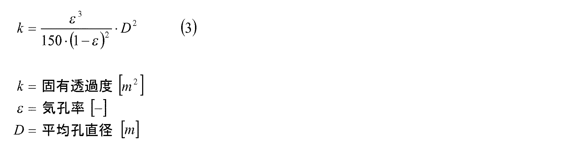
固有の透過度kは、多孔性の材料の固有の性質であり、主に孔径Dおよび孔体積εならびに孔通路の屈曲度により影響を与えられ得る。 The intrinsic permeability k is an intrinsic property of the porous material and can be influenced mainly by the pore diameter D and pore volume ε and the curvature of the pore passage.
透過度kの簡単な評価は、Ergunの式(屈曲度を有しない)により求められる。 A simple evaluation of the permeability k is obtained by Ergun's formula (having no degree of bending).
この式は、大まかな評価を提供する。実際の材料では、屈曲度、孔径分布および場合によっては異方性が偏差をもたらすので、具体的な事例のためには測定値を使用する必要がある。 This formula provides a rough evaluation. In actual materials, the degree of bending, pore size distribution and in some cases anisotropy can cause deviations, so measurements need to be used for specific cases.
さらに、良好な腐食耐性を有しない材料に、腐食に強い保護層を備えることができ、この場合、この保護層は、溶融物に対する接触領域にも、孔の内側の表面にも設けられていてよい。高温での使用時、特に溶融物使用時に耐性を有する材料の選択は、当業者にとって、裏付けされた経験から容易に可能である。 Furthermore, a material that does not have good corrosion resistance can be provided with a protective layer that is resistant to corrosion, in which case this protective layer is provided either on the contact area for the melt or on the inner surface of the hole. Good. The selection of materials that are resistant when used at high temperatures, particularly when using melts, is readily possible for those skilled in the art from supported experience.
400℃〜800℃の溶融物温度を有する亜鉛またはアルミニウム溶融物内での使用のためには、特に腐食耐性の、溶融物によって濡れにくいセラミックス材料、たとえば窒化珪素、SiAlON,窒化アルミニウム、ニホウ化チタンまたは酸化アルミニウム材料、炭化珪素材料、または炭素材料が有利である。 For use in zinc or aluminum melts having a melt temperature of 400 ° C. to 800 ° C., ceramic materials that are particularly corrosion resistant and difficult to wet by the melt, such as silicon nitride, SiAlON, aluminum nitride, titanium diboride Alternatively, an aluminum oxide material, a silicon carbide material, or a carbon material is advantageous.
構成部材のための材料の気体透過性、ひいては多孔性(Porositaet)を実現するために、公知の方法および構造化法が使用され得る。これらの方法には、粉末粒子の中間空間を維持しながら粉末を焼結すること、短繊維または長繊維の焼結、スペース維持材料の使用、テンプレート成形法(Abformungsmethode aus Template)、発泡法等が使用され得る。 Known methods and structuring methods can be used to achieve gas permeability of the material for the component, and thus Porositaet. These methods include sintering powder while maintaining the intermediate space of the powder particles, sintering of short or long fibers, use of space maintaining materials, Abformungsmethode aus Template, foaming method, etc. Can be used.
気孔は、気体の透過を可能にするいわゆる開気孔性でなければならない。このことは均一に分配された等方性の孔の場合、約35%以上の全体的な孔の割合から可能である。しかし、孔通路が方向付けられている場合、より小さな孔割合でも既に十分な透過性が達成され得る。 The pores must be so-called open pores that allow gas permeation. This is possible from an overall pore fraction of about 35% or more for uniformly distributed isotropic pores. However, if the hole passages are oriented, sufficient permeability can already be achieved with a smaller hole ratio.
孔径は、1〜1000μmの範囲であってよい。この場合、有利には5〜200μmの範囲の孔を有する材料が使用され得る。多孔性の材料は、通常、特定の孔径分布を有している。この孔径分布は、典型的には、水銀圧入(水銀圧入式ポロシメータ)法または透過度ポロメトリー法(Permabilitaetasporometrie)により求められる。使用のために好適には、孔径分布(LNVT, RRSB-VT, GGS-VT)の公知の分布関数を起点として、d90/d10≧0.5の比により説明される密な孔径分布が有利である。 The pore diameter may be in the range of 1-1000 μm. In this case, materials with pores in the range from 5 to 200 μm can be used advantageously. Porous materials usually have a specific pore size distribution. This pore size distribution is typically determined by a mercury intrusion (mercury intrusion porosimeter) method or a permeability porometry method (Permabilitaetasporometrie). Preferably for use, a dense pore size distribution described by a ratio of d90 / d10 ≧ 0.5 starting from a known distribution function of pore size distribution (LNVT, RRSB-VT, GGS-VT) is advantageous. is there.
さらに、いわゆる非対称な、または勾配を有する気孔率または孔割合および孔径を備えた構成部材を使用することが可能である。たとえば、比較的粗い孔を有する材料を支持体として使用することがよく、この場合、該支持体上に細かい孔の層である薄い層(メンブラン)が被着されている。または、(素材および/または孔特性に関して互いに異なる)互いに異なる材料から成る2つ以上の成形部分を、透過方向に関して相前後して使用することも同様に可能である。 Furthermore, it is possible to use components with a so-called asymmetric or gradient porosity or pore ratio and pore diameter. For example, a material having relatively coarse pores is often used as a support, in which case a thin layer (membrane), which is a layer of fine pores, is deposited on the support. Alternatively, it is equally possible to use two or more molded parts made of different materials (different from each other in terms of material and / or pore properties) in succession with respect to the transmission direction.
気体透過性の多孔性の材料は、種々異なる幾何学形状の構成部材として使用され得る。この形状は、たとえば真っ直ぐまたは湾曲したディスク、シリンダ、片側で閉じたシリンダ(スリーブ)、円錐台、またはコーンのような複雑な形状である。選択は、中空体の開口内における気体透過性の材料の配置に合わせられる。均一な壁厚さを有する形状が有利である。 Gas permeable porous materials can be used as components of different geometric shapes. This shape is a complex shape such as, for example, a straight or curved disk, cylinder, cylinder closed on one side (sleeve), truncated cone, or cone. The choice is tailored to the arrangement of the gas permeable material within the opening of the hollow body. A shape with a uniform wall thickness is advantageous.
さらに、複数の構成部材を中空体の複数の開口内に配置することも可能である。同様に本発明によれば、中空体の1つの開口の内部に、複数の構成部材を相前後して配置することも可能である。1つの中空体内に複数の構成部材が存在している場合、個々の構成部材の材料は互いに異なっていてよく、特に破裂圧耐性、気孔率および/または透過度に関して互いに異なって形成されていてよい。 Furthermore, it is also possible to arrange a plurality of constituent members in a plurality of openings of the hollow body. Similarly, according to the present invention, it is also possible to arrange a plurality of constituent members one after the other inside one opening of the hollow body. When there are a plurality of constituent members in one hollow body, the materials of the individual constituent members may be different from each other, and particularly may be formed different from each other with respect to bursting pressure resistance, porosity and / or permeability. .
同様に、本発明によれば、たとえば局所的な厚さ減少部が存在しているように、構成部材を構造化することが可能である。厚さ減少部は、破裂事例における目標破断箇所を成すことができる。この厚さ減少部は、構成部材の厚さの5%以上であってよい。 Similarly, according to the present invention, it is possible to structure the component members such that, for example, a local thickness reduction portion exists. The thickness reduction portion can form a target breakage point in the burst case. The thickness reducing portion may be 5% or more of the thickness of the constituent member.
通流面積の決定は、たとえば溶融浴内への浸漬または予熱ステップによる中空体の加熱時に、ガス、または中空体に含まれているか、温度上昇により発生した物質の膨張により典型的に発生する、予測される付加的な気体体積に合わせられる。このことは、主に、中空体の中空室体積、温度差、および気体組成もしくは物質組成に依存する。気体透過性の材料の選択および該材料の固有の透過度を求めることにより、当業者により公知のDarci式を用いて容易に、構成部材を通じた十分な気体流出を達成し、かつ中空体内の内圧を相応して減じるかまたは制限するために必要となる成形部材の所要の面積および厚さを求めることができる。いずれの場合も構成部材の所要の横断面は極めて小さく形成され、つまり中空体の外周面に対してたとえば<1%であってよく、通流厚さは、単に数ミリメートルから数センチメートルである。したがって、溶融めっき装置の中空ロールの場合、好適には1つまたは両方の支承中空ジャーナルまたは中空ロールの端面への組込みが行われ、この場合、平坦なディスクまたはシリンダ形のスリーブとしての構成部材の使用が有利である。 The determination of the flow area typically occurs, for example, during the heating of the hollow body by immersion in a molten bath or by a preheating step, due to the expansion of the gas or substances contained in the hollow body or generated by an increase in temperature, Matched to the anticipated additional gas volume. This mainly depends on the hollow chamber volume of the hollow body, the temperature difference, and the gas composition or material composition. By selecting a gas permeable material and determining the inherent permeability of the material, it is easy to achieve sufficient gas outflow through the component using the Darci equation known by those skilled in the art, and the internal pressure in the hollow body. It is possible to determine the required area and thickness of the molded part required to reduce or limit the correspondingly. In any case, the required cross-section of the component is very small, i.e. it may be <1%, for example, with respect to the outer peripheral surface of the hollow body, and the flow thickness is simply a few millimeters to a few centimeters . Thus, in the case of a hot roll in a hot dipping apparatus, one or both of the bearing hollow journals or the hollow roll are preferably integrated into the end face, in which case the component as a flat disk or cylinder shaped sleeve Use is advantageous.
成形部材を過圧防止部または破裂ディスクとして同時に設計する場合、互いに異なる機械的な特性、互いに異なる透過度および/または互いに異なる濡れ挙動を有する2つ以上の構成部材を使用することも可能である。これにより、唯1つの構成部材が特定の圧力負荷時に破裂するのに対して、1つまたは複数の別の構成部材が脱気装置内に損傷なしに留まり、溶融物の侵入は、第1のディスクの破壊後も阻止されるか、遅延される。この場合、侵入する溶融物に意図的に反応し、該溶融物の通過を遅延させるまたは阻止する材料も使用され得る。 If the molded part is designed as an overpressure prevention part or a rupture disk at the same time, it is also possible to use two or more components having different mechanical properties, different permeability and / or different wetting behavior . This allows only one component to rupture at a particular pressure load, while one or more other components remain intact in the degasser and the intrusion of the melt is the first It is blocked or delayed even after the disk is destroyed. In this case, a material that intentionally reacts to the invading melt and delays or prevents the passage of the melt can also be used.
1つまたは複数の構成部材の組込みのためには、溶融物の侵入に対する密閉性も保証する気密な装置または締付け部材もしくはクランプ(Einspannung)が使用されることが考慮され得る。 For the incorporation of one or more components, it can be considered that an airtight device or a clamping member or an Einspannung that also guarantees hermeticity against intrusion of the melt is used.
さらに、中空体の材料に対して異なる熱膨張係数を備える多孔性の材料の選択時に、温度変更時に機械的な応力が発生しないかまたは僅かにしか発生しないことが考慮されなければならない。取付けのためには、ろう付け、溶接または接着剤結合のような素材接続による結合技術が使用されるか、またはクランプ結合、収縮結合またはねじ締結のような素材接続式ではない結合部も使用され得る。この場合、付加的なシール材料が使用され得る。低い熱膨張係数を有する多孔性のセラミックス材料の使用時に、弾性的なシール材料を使用した面状のクランプ結合が有利である。この場合、シール材料として、たとえば炭素、セラミックス繊維または雲母含有のシール材料が有利である。この場合、結合部が着脱可能であると有利であり、これにより、多孔性の材料から成る成形部材およびシール材料をたとえば中空ロールの変更または加工時に容易に交換することができる。 Furthermore, when selecting a porous material with a different coefficient of thermal expansion relative to the hollow body material, it must be taken into account that no mechanical stress is generated or only a small amount is generated when the temperature is changed. For attachment, material connection techniques such as brazing, welding or adhesive bonding are used, or non-material connection joints such as clamping, shrinkage or screw fastening are also used. obtain. In this case, additional sealing materials can be used. When using a porous ceramic material having a low coefficient of thermal expansion, a planar clamp connection using an elastic sealing material is advantageous. In this case, as a sealing material, for example, a sealing material containing carbon, ceramic fibers or mica is advantageous. In this case, it is advantageous if the coupling part is detachable, so that the molded member and the sealing material made of a porous material can be easily exchanged, for example, when changing or processing the hollow roll.
本発明に係る解決手段は、特に溶融めっきコーティング装置に用いられるロール装置に関して公知の先行技術とは以下の点で相違する。
−溶融物浴に対するジャーナルのシールが不要である。
−ジャーナルの中空室を周辺雰囲気に接続する付加的な開口は省略され得る。
−ジャーナルの中空室内への溶融物の侵入が効果的に阻止され得る。
−気体透過性の材料、特に気体透過性のセラミックスがロールの開口を閉鎖する構成部材として使用され得る。
The solution according to the present invention differs from the known prior art particularly in relation to a roll apparatus used in a hot dipping coating apparatus in the following points.
-No need to seal the journal against the melt bath.
-Additional openings connecting the hollow chamber of the journal to the ambient atmosphere can be omitted.
-The penetration of the melt into the hollow chamber of the journal can be effectively prevented.
A gas permeable material, in particular a gas permeable ceramic, can be used as a component closing the opening of the roll.
本発明の解決手段は、先行技術に対して以下の重要な利点を有している。
−少ない摩耗を伴う著しく単純な構造原理。これにより、浴設備の大幅な寿命延長が少ないメンテナンス手間で生じる。
−金属コーティング浴内での中空ロールの安全な使用の実現。これにより、作業安全性の著しい向上と同時に最適な競争力を可能にすることができる。
The solution of the present invention has the following important advantages over the prior art.
A remarkably simple structural principle with little wear. As a result, the maintenance time of the bath equipment is greatly reduced, resulting in less maintenance.
-Realization of safe use of hollow rolls in metal coating baths. Thereby, the optimum competitiveness can be made possible at the same time that the work safety is remarkably improved.
本発明の解決手段を以下に1つの実施の形態につき詳しく説明する。 The solution of the present invention will be described in detail below for one embodiment.
実施例
鋼帯材の溶融めっきコーティングに用いられる中空の底部ロールは680℃のアルミニウム溶融浴に装入される。ロールの円筒状の内側中空室は、直径680mm、長さ1670mmの寸法を有している。この寸法は、0.606m3の体積を成し、この体積には使用前に20℃の空気が充填されている。溶融浴内へのロールの浸漬時に、空気は静止した状態でも680℃の浴温度にまで加熱される。これにより、1394m3の空気の体積膨張が生じる。ロールは2.5mの深さまで溶融浴内に沈められるので、2.38g/cm3のアルミニウムの密度では0.06MPaの流体静力学的な圧力(静圧)がロールに作用する。
EXAMPLE A hollow bottom roll used for hot dip coating of steel strip is placed in a 680 ° C. aluminum molten bath. The cylindrical inner hollow chamber of the roll has dimensions of 680 mm in diameter and 1670 mm in length. This dimension has a volume of 0.606 m 3 and is filled with 20 ° C. air before use. When the roll is immersed in the molten bath, the air is heated to a bath temperature of 680 ° C. even in a stationary state. This causes a volume expansion of 1394 m 3 air. Since the roll is submerged in the molten bath to a depth of 2.5 m, a hydrostatic pressure (static pressure) of 0.06 MPa acts on the roll at an aluminum density of 2.38 g / cm 3 .
ロールの支承のためのジャーナル内には、40mmの直径の一貫して延びる円筒状の孔が加工されている。この孔は、ロールの内部中空室を外側の環境に接続している。支承ジャーナルの円筒状の孔は、30mmの長さで50mmの直径を有する円筒状のキャビティへと拡張されている。このキャビティ内には、48mmの直径および5mmの厚さを有する多孔性のセラミックスから成るディスクが導入されている。このディスクは、両側で1mmの厚さのグラファイトフィルムから成る4mm幅のリングシールに載置していて、機械的な緊締リングにより押圧されている。これにより、40mmの多孔性のセラミックスディスクの貫流可能な自由な横断面が生じる。中空ロールの浸漬後に溶融物はジャーナルのシリンダ状の孔内へ多孔性のセラミックスディスクに達するまで侵入する。 A consistently extending cylindrical hole with a diameter of 40 mm is machined in the journal for supporting the roll. This hole connects the inner hollow chamber of the roll to the outside environment. The cylindrical hole of the bearing journal is expanded into a cylindrical cavity with a length of 30 mm and a diameter of 50 mm. In this cavity, a disc made of porous ceramics having a diameter of 48 mm and a thickness of 5 mm is introduced. This disk is mounted on a 4 mm wide ring seal made of graphite film with a thickness of 1 mm on both sides and pressed by a mechanical fastening ring. This creates a free cross section through which a 40 mm porous ceramic disk can flow. After immersion of the hollow roll, the melt penetrates into the cylindrical hole of the journal until it reaches the porous ceramic disk.
セラミックスディスクは、12μmの平均孔幅で、51%の全体気孔率を有する多孔性の窒化珪素セラミックスから成っている。この場合、孔径分布は密に形成されていて、d90/d10比=3を有している(水銀圧入法により求められた値)。透過度ポロメトリー法により求められたこのセラミックスの固有の透過度は、1.7x10−12m2である。このような透過度および存在する幾何学形状では、中空ロールの内部で膨張する気体体積は600秒以内に溶融物内へ流出することにより解消される。この場合、Darciの式により、短期間で、0.18MPaの最大耐圧が発生する。 The ceramic disc is made of porous silicon nitride ceramics having an average pore width of 12 μm and an overall porosity of 51%. In this case, the pore size distribution is dense and has a d90 / d10 ratio = 3 (value determined by mercury porosimetry). The intrinsic permeability of this ceramic, determined by the permeability porometry method, is 1.7 × 10 −12 m 2 . With such permeability and existing geometry, the gas volume expanding inside the hollow roll is eliminated by flowing into the melt within 600 seconds. In this case, the maximum breakdown voltage of 0.18 MPa is generated in a short period according to the Darci equation.
窒化珪素と700℃のアルミニウム溶融物との接触角(濡れ角)は、160°であり(D.A Weirauch Jr., Technologically significant capillary phenomena in high-temperature materials processing -Examples drawn from the aluminum industry, Current Opinion in Solid State & Material Science 9 (2005) 230-240)、680℃のアルミニウム溶融物の表面張力は、1.07J/m2である(Kh.Kh Kalazhokov, Z.Kh. Kalazhokov, Kh.B. Khokonov, Surface Tension of Pure Aluminum Melt, Technical Physics Vol 48, No.2, 2003, 272-273)。多孔性のセラミックスと680℃の高温のアルミニウム溶融物との接触時に、Washburnの式により、−0.35MPaの負の毛細管圧力が生じ、つまりディスクは濡れず、溶融物の流体静力学的な圧力がディスクに作用した場合も浸透は行われない。 The contact angle (wetting angle) between silicon nitride and 700 ° C. aluminum melt is 160 ° (DA Weirauch Jr., Technologically significant capillary phenomena in high-temperature materials processing -Examples drawn from the aluminum industry, Current Opinion in Solid State & Material Science 9 (2005) 230-240), the surface tension of an aluminum melt at 680 ° C. is 1.07 J / m 2 (Kh.Kh Kalazhokov, Z.Kh. Kalazhokov, Kh.B. Khokonov Surface Tension of Pure Aluminum Melt, Technical Physics Vol 48, No.2, 2003, 272-273). When contacting the porous ceramic with a hot aluminum melt at 680 ° C., the Washburn equation results in a negative capillary pressure of −0.35 MPa, ie the disk does not get wet and the hydrostatic pressure of the melt No permeation occurs when the is applied to the disc.
ディスクの破裂圧耐性は、同様の締付け部材を用いて事前テストにより求められる。この破裂圧耐性は約1.2MPaであってよく、これにより、ロールの内部における予期しない圧力上昇時のディスクの破裂およびジャーナル孔を通じた溶融物内への気体の流出による圧力低減が達成され得る。 The burst pressure resistance of the disc is determined by a preliminary test using a similar tightening member. This burst pressure resistance can be about 1.2 MPa, which can achieve pressure reduction due to the bursting of the disk and the outflow of gas through the journal holes into the melt during an unexpected pressure increase inside the roll. .
Claims (16)
該中空体の、特定の用途に役立つわけではない領域に、前記中空体の中空室へ通じる開口が存在しており、該開口は、中空体を取り囲む前記溶融物に対して、気体透過性の金属材料またはセラミックス材料から成る構成部材により閉じられていることを特徴とする、金属または合金、ガラスまたはポリマから成る溶融物内にある中空体内の圧力を低減する装置。 A device for reducing the pressure in a hollow body in a melt consisting of metal or alloy, glass or polymer ,
Of the hollow body, in a region not serve a particular application, the provided apertures which Ru leads into the hollow chamber of the hollow body is present, the opening is to the melt surrounding the hollow body, a gas permeable characterized in that the sex of a metallic material or a ceramic material is closed by configuration member Ru formed to reduce the pressure of the hollow body in the melt consisting of metal or alloy, glass or a polymer device.
Applications Claiming Priority (3)
| Application Number | Priority Date | Filing Date | Title |
|---|---|---|---|
| DE201110078878 DE102011078878B4 (en) | 2011-07-08 | 2011-07-08 | DEVICE FOR PRESSURE REDUCTION IN HOLLOW BODIES IN MEDIA AT HIGHER TEMPERATURES |
| DE102011078878.6 | 2011-07-08 | ||
| PCT/EP2012/062729 WO2013007539A1 (en) | 2011-07-08 | 2012-06-29 | Device for reducing pressure in hollow bodies in media at higher temperatures |
Publications (2)
| Publication Number | Publication Date |
|---|---|
| JP2014524981A JP2014524981A (en) | 2014-09-25 |
| JP5980324B2 true JP5980324B2 (en) | 2016-08-31 |
Family
ID=46614439
Family Applications (1)
| Application Number | Title | Priority Date | Filing Date |
|---|---|---|---|
| JP2014519495A Expired - Fee Related JP5980324B2 (en) | 2011-07-08 | 2012-06-29 | Device for reducing the pressure in a hollow body in a hot medium |
Country Status (8)
| Country | Link |
|---|---|
| US (1) | US9683598B2 (en) |
| EP (1) | EP2729591B1 (en) |
| JP (1) | JP5980324B2 (en) |
| KR (1) | KR101911418B1 (en) |
| CN (1) | CN103649360B (en) |
| DE (1) | DE102011078878B4 (en) |
| ES (1) | ES2722206T3 (en) |
| WO (1) | WO2013007539A1 (en) |
Families Citing this family (4)
| Publication number | Priority date | Publication date | Assignee | Title |
|---|---|---|---|---|
| DE102014118316B4 (en) * | 2014-12-10 | 2017-07-06 | Thyssenkrupp Ag | Roller for deflecting or guiding a metal strip to be coated in a metallic melt bath |
| DE102015211489B3 (en) * | 2015-06-22 | 2016-06-30 | Thyssenkrupp Ag | Roller for deflecting or guiding a metal strip to be coated in a metallic melt bath |
| FR3097636B1 (en) | 2019-06-20 | 2021-07-02 | Christian Hug | Autonomous and irreversible pressure variation detector |
| WO2021041491A1 (en) * | 2019-08-29 | 2021-03-04 | Roto-Die Company, Inc. | Reduced weight magnetic cylinder |
Family Cites Families (24)
| Publication number | Priority date | Publication date | Assignee | Title |
|---|---|---|---|---|
| US3374039A (en) * | 1965-09-01 | 1968-03-19 | Gen Motors Corp | Antifriction bearing |
| FR90350E (en) * | 1965-10-21 | 1967-11-24 | Air Liquide | Process for treating liquid metals, applicable in particular to the production of nodular cast iron |
| US3527510A (en) * | 1968-12-05 | 1970-09-08 | Gen Motors Corp | Antihammer device for air spindles |
| US3645589A (en) * | 1970-12-03 | 1972-02-29 | Gen Motors Corp | Air bearing with low tensile strength permeable sleeve |
| US3645590A (en) * | 1970-12-17 | 1972-02-29 | Gen Motors Corp | Carbon-graphite gas-bearing roll |
| DE3140438A1 (en) * | 1981-10-12 | 1983-04-21 | Manfred Dipl.-Ing. 6991 Igersheim Wittenstein | Sealing screw with gas pressure equalisation |
| DE4307282C2 (en) * | 1992-03-06 | 1996-12-05 | Eko Stahl Gmbh | Roller arrangement for strip or wire-shaped items to be coated to be coated in a molten metal bath |
| JP3191558B2 (en) * | 1994-04-08 | 2001-07-23 | 株式会社日立製作所 | Sliding structure and continuous hot metal plating equipment using it |
| DE19511943C2 (en) * | 1995-03-31 | 1998-04-09 | Duma Masch Anlagenbau | Device for the continuous coating of metal strip |
| FR2735499B1 (en) * | 1995-06-15 | 1997-09-05 | Clecim Sa | DEFLECTOR ROLLER FOR A STRIP PRODUCT |
| JP2002285310A (en) * | 2001-03-22 | 2002-10-03 | Daido Steel Co Ltd | Roll for hot dip galvanizing treatment |
| US6692689B2 (en) * | 2001-12-14 | 2004-02-17 | Jorge A. Morando | Sink roll assembly with forced hydrodynamic film lubricated bearings and self-aligning holding arms |
| DE10227778A1 (en) | 2002-06-21 | 2004-01-08 | Band-Zink Gmbh | coater |
| DE10319840B3 (en) * | 2003-04-24 | 2004-06-17 | Duma Maschinen Und Anlagenbau Gmbh | Shaft bearing for roller immersed in bath of molten zinc used to galvanize sheet steel, employs inductances providing magnetic sealing against molten metal |
| CN100494466C (en) * | 2003-12-11 | 2009-06-03 | 日立金属株式会社 | Roll for molten metal plating bath |
| US7257360B2 (en) * | 2003-12-30 | 2007-08-14 | Xerox Corporation | Induction heated heat pipe fuser with low warm-up time |
| JP4474639B2 (en) * | 2004-04-06 | 2010-06-09 | 日立金属株式会社 | Roll for continuous molten metal plating |
| DE102004032324B3 (en) * | 2004-07-02 | 2005-12-15 | Duma Maschinen Und Anlagenbau Gmbh | Storage for a dipped in a molten metal bath arranged deflection or guide roller |
| US20080274006A1 (en) * | 2007-05-01 | 2008-11-06 | Mark Bright | Overlay cladding for molten metal processing |
| DE102007045200A1 (en) * | 2007-09-21 | 2009-04-02 | Sms Demag Ag | Hot-dip coating plant |
| DE202008001972U1 (en) * | 2008-02-13 | 2008-05-29 | Fhf Funke + Huster Fernsig Gmbh | Housing for an electrical circuit installation in explosion-proof design |
| JP2010255043A (en) * | 2009-04-24 | 2010-11-11 | Kyocera Corp | Roll for hot dip metal coating |
| DE102009034017A1 (en) * | 2009-07-21 | 2011-01-27 | Sms Siemag Ag | Sealing a hot dip coating device |
| DE102009040961A1 (en) * | 2009-09-11 | 2011-03-24 | Staubach, Helmut, Prof. | Conical-shaped closing part for a flow- and ventilation opening that is guided to a cavity of a workpiece and has a diameter, comprises an end turned to a cavity, an end turned away from the cavity, and a mantle surface |
-
2011
- 2011-07-08 DE DE201110078878 patent/DE102011078878B4/en not_active Expired - Fee Related
-
2012
- 2012-06-29 EP EP12743400.9A patent/EP2729591B1/en active Active
- 2012-06-29 US US14/130,855 patent/US9683598B2/en not_active Expired - Fee Related
- 2012-06-29 JP JP2014519495A patent/JP5980324B2/en not_active Expired - Fee Related
- 2012-06-29 CN CN201280034009.3A patent/CN103649360B/en not_active Expired - Fee Related
- 2012-06-29 WO PCT/EP2012/062729 patent/WO2013007539A1/en active Application Filing
- 2012-06-29 KR KR1020147003340A patent/KR101911418B1/en active IP Right Grant
- 2012-06-29 ES ES12743400T patent/ES2722206T3/en active Active
Also Published As
| Publication number | Publication date |
|---|---|
| JP2014524981A (en) | 2014-09-25 |
| EP2729591A1 (en) | 2014-05-14 |
| ES2722206T3 (en) | 2019-08-08 |
| EP2729591B1 (en) | 2019-02-06 |
| US9683598B2 (en) | 2017-06-20 |
| DE102011078878A1 (en) | 2013-01-10 |
| CN103649360B (en) | 2016-07-20 |
| CN103649360A (en) | 2014-03-19 |
| KR101911418B1 (en) | 2018-10-24 |
| US20140341493A1 (en) | 2014-11-20 |
| WO2013007539A1 (en) | 2013-01-17 |
| KR20140061391A (en) | 2014-05-21 |
| DE102011078878B4 (en) | 2015-05-07 |
Similar Documents
| Publication | Publication Date | Title |
|---|---|---|
| JP5980324B2 (en) | Device for reducing the pressure in a hollow body in a hot medium | |
| Aneziris et al. | Reactive filters for steel melt filtration | |
| JP5302836B2 (en) | Stopper control type immersion nozzle | |
| NO159453B (en) | DEVICE FOR MILT METAL FILTERING. | |
| EP3140066B1 (en) | Refractory ceramic casting nozzle | |
| JP4517386B2 (en) | Casting nozzle | |
| JP2015502260A (en) | Expandable sealing of metal casting equipment | |
| TW201441177A (en) | Zirconia based coating for refractory elements and refractory element comprising such coating | |
| CA2923382C (en) | Refractory ceramic gas purging element | |
| CN104487403B (en) | Carbon material with thermal spraying coating | |
| Muscat et al. | The effect of pore size on the infiltration kinetics of aluminum in titanium carbide preforms | |
| Jie et al. | Friction and wear behavior of micro arc oxidation coatings on magnesium alloy at high temperature | |
| BE1019916A5 (en) | BOTTOM CAST PIPE FOR INSTALLATION ON THE BOTTOM OF A METALLURGICAL BARREL. | |
| WO2013021677A1 (en) | Graphite crucible | |
| EP1893370B1 (en) | Stopper rod | |
| CA2205632C (en) | Impregnated ceramic riser tube and method of manufacturing same | |
| Pan et al. | Kinetic study of cobalt silicide infiltration into silicon carbide preforms | |
| JP2018004105A (en) | Molten metal treatment device and manufacturing method of the same | |
| JP2004243336A (en) | Continuous casting nozzle for copper alloy | |
| SU1077141A1 (en) | Metal conduit of horizontal continuous caster | |
| WO2003082500A1 (en) | Thermal shock resistant casting element and manufacturing process thereof | |
| JPS6124458B2 (en) | ||
| JP2014000585A (en) | Method of using ladle nozzle | |
| JP2008080384A (en) | Plate-shaped refractory for sliding nozzle | |
| JP2016043371A (en) | Continuous casting mold |
Legal Events
| Date | Code | Title | Description |
|---|---|---|---|
| A621 | Written request for application examination |
Free format text: JAPANESE INTERMEDIATE CODE: A621 Effective date: 20150331 |
|
| A977 | Report on retrieval |
Free format text: JAPANESE INTERMEDIATE CODE: A971007 Effective date: 20151221 |
|
| A131 | Notification of reasons for refusal |
Free format text: JAPANESE INTERMEDIATE CODE: A131 Effective date: 20160105 |
|
| A601 | Written request for extension of time |
Free format text: JAPANESE INTERMEDIATE CODE: A601 Effective date: 20160405 |
|
| A521 | Request for written amendment filed |
Free format text: JAPANESE INTERMEDIATE CODE: A523 Effective date: 20160602 |
|
| TRDD | Decision of grant or rejection written | ||
| A01 | Written decision to grant a patent or to grant a registration (utility model) |
Free format text: JAPANESE INTERMEDIATE CODE: A01 Effective date: 20160627 |
|
| A61 | First payment of annual fees (during grant procedure) |
Free format text: JAPANESE INTERMEDIATE CODE: A61 Effective date: 20160726 |
|
| R150 | Certificate of patent or registration of utility model |
Ref document number: 5980324 Country of ref document: JP Free format text: JAPANESE INTERMEDIATE CODE: R150 |
|
| R250 | Receipt of annual fees |
Free format text: JAPANESE INTERMEDIATE CODE: R250 |
|
| LAPS | Cancellation because of no payment of annual fees |