JP5980025B2 - Fuel cell cogeneration system - Google Patents
Fuel cell cogeneration system Download PDFInfo
- Publication number
- JP5980025B2 JP5980025B2 JP2012158866A JP2012158866A JP5980025B2 JP 5980025 B2 JP5980025 B2 JP 5980025B2 JP 2012158866 A JP2012158866 A JP 2012158866A JP 2012158866 A JP2012158866 A JP 2012158866A JP 5980025 B2 JP5980025 B2 JP 5980025B2
- Authority
- JP
- Japan
- Prior art keywords
- heated fluid
- exhaust gas
- refrigerant
- cooler
- supply amount
- Prior art date
- Legal status (The legal status is an assumption and is not a legal conclusion. Google has not performed a legal analysis and makes no representation as to the accuracy of the status listed.)
- Expired - Fee Related
Links
Images


Classifications
-
- Y—GENERAL TAGGING OF NEW TECHNOLOGICAL DEVELOPMENTS; GENERAL TAGGING OF CROSS-SECTIONAL TECHNOLOGIES SPANNING OVER SEVERAL SECTIONS OF THE IPC; TECHNICAL SUBJECTS COVERED BY FORMER USPC CROSS-REFERENCE ART COLLECTIONS [XRACs] AND DIGESTS
- Y02—TECHNOLOGIES OR APPLICATIONS FOR MITIGATION OR ADAPTATION AGAINST CLIMATE CHANGE
- Y02A—TECHNOLOGIES FOR ADAPTATION TO CLIMATE CHANGE
- Y02A30/00—Adapting or protecting infrastructure or their operation
- Y02A30/27—Relating to heating, ventilation or air conditioning [HVAC] technologies
- Y02A30/274—Relating to heating, ventilation or air conditioning [HVAC] technologies using waste energy, e.g. from internal combustion engine
-
- Y—GENERAL TAGGING OF NEW TECHNOLOGICAL DEVELOPMENTS; GENERAL TAGGING OF CROSS-SECTIONAL TECHNOLOGIES SPANNING OVER SEVERAL SECTIONS OF THE IPC; TECHNICAL SUBJECTS COVERED BY FORMER USPC CROSS-REFERENCE ART COLLECTIONS [XRACs] AND DIGESTS
- Y02—TECHNOLOGIES OR APPLICATIONS FOR MITIGATION OR ADAPTATION AGAINST CLIMATE CHANGE
- Y02E—REDUCTION OF GREENHOUSE GAS [GHG] EMISSIONS, RELATED TO ENERGY GENERATION, TRANSMISSION OR DISTRIBUTION
- Y02E60/00—Enabling technologies; Technologies with a potential or indirect contribution to GHG emissions mitigation
- Y02E60/30—Hydrogen technology
- Y02E60/50—Fuel cells
Description
本発明は、燃料電池装置の排熱にて被加熱流体を加熱し、その加熱された被加熱流体を熱利用箇所に供給自在に構成されている燃料電池コージェネレーションシステムに関する。 The present invention relates to a fuel cell cogeneration system configured to heat a heated fluid with exhaust heat of a fuel cell device and to supply the heated heated fluid to a heat utilization location.
上記のような燃料電池コージェネレーションシステムでは、例えば、被加熱流体を貯留する貯湯タンクと、その貯湯タンクから被加熱流体を取り出して燃料電池装置に供給して加熱し、その加熱された被加熱流体を貯湯タンクに戻す被加熱流体循環手段とを備え、その貯湯タンクに貯留されている被加熱流体を給湯箇所等に供給するようにしている。 In the fuel cell cogeneration system as described above, for example, a hot water storage tank that stores the heated fluid, and the heated fluid is taken out from the hot water storage tank, supplied to the fuel cell device, heated, and the heated heated fluid And a heated fluid circulating means for returning the heated fluid to the hot water storage tank, and the heated fluid stored in the hot water storage tank is supplied to a hot water supply location or the like.
このようなシステムとして、従来、被加熱流体を加熱するための熱源として、燃料電池装置の排熱を利用するだけでなく、圧縮式ヒートポンプ装置を備え、そのヒートポンプ装置の凝縮器にて被加熱流体を加熱するものがある(例えば、特許文献1参照。)。
この特許文献1に記載のシステムでは、燃料電池装置の排ガスをヒートポンプ装置の蒸発器に供給することで、外気だけでなく、排ガスが有する熱をもヒートポンプ装置の熱源としている。貯湯タンクには、燃料電池装置の排熱にて予熱された被加熱流体を貯留しており、高温の被加熱流体を貯湯タンクに貯湯する場合に、圧縮式ヒートポンプ装置を運転させて、燃料電池装置の排ガスや外気を熱源として、高温の被加熱流体を貯湯している。
As such a system, conventionally, not only the exhaust heat of the fuel cell device is used as a heat source for heating the fluid to be heated, but also a compression heat pump device is provided, and the fluid to be heated in the condenser of the heat pump device (For example, refer to Patent Document 1).
In the system described in Patent Document 1, by supplying the exhaust gas of the fuel cell device to the evaporator of the heat pump device, not only the outside air but also the heat of the exhaust gas is used as the heat source of the heat pump device. The hot water storage tank stores the heated fluid preheated by the exhaust heat of the fuel cell device. When the hot heated fluid is stored in the hot water storage tank, the compression heat pump device is operated to operate the fuel cell. A hot fluid to be heated is stored using the exhaust gas or outside air of the apparatus as a heat source.
このようなシステムでは、例えば、天然ガス等の炭化水素を燃料電池の原燃料として用いる場合、原燃料に水蒸気を混合させて、COとH2に改質させてから燃料電池にて反応させている。この改質反応に必要な水を改質水と呼んでおり、改質水は、水道水等から供給すると不純物が多く含まれているため、燃料電池装置の排ガスを冷却して得られる凝縮水を用いるのが主となっている。凝縮水で改質水の必要量を賄うことができれば、水道水から不純物を除去する水浄化装置が不要となる、或いは、水浄化装置を備えるにしても能力的に小型のものを備えるだけでよく、装置構成の簡略化が図ることができる。そこで、凝縮水で改質水の必要量を賄う、いわゆる「水自立」を成立させることが求められている。 In such a system, for example, when a hydrocarbon such as natural gas is used as a raw fuel of a fuel cell, the raw fuel is mixed with water vapor and reformed into CO and H 2 and then reacted in the fuel cell. Yes. The water required for this reforming reaction is called reformed water, and since reformed water contains a large amount of impurities when supplied from tap water or the like, condensed water obtained by cooling the exhaust gas of the fuel cell device Is mainly used. If the required amount of reformed water can be covered with condensed water, a water purification device that removes impurities from tap water becomes unnecessary, or even if it is equipped with a water purification device, it only has a small capacity. It is possible to simplify the apparatus configuration. Therefore, it is required to establish a so-called “water independence” in which the required amount of reformed water is covered with condensed water.
水自立を成立させるためには、燃料電池装置の排ガスを水自立用設定温度(例えば、40℃)程度まで冷却させる必要がある。これにより、排ガスと被加熱流体とを熱交換させて排ガスが有する熱を被加熱流体にて回収する場合には、水自立を成立させるために、被加熱流体の温度を水自立用設定温度(例えば、40℃)以下にしておくことが求められる。しかしながら、放熱器等により被加熱流体の温度を水自立用設定温度(例えば、40℃)以下まで冷却させると、せっかく回収した燃料電池装置の排熱を放熱することになり、エネルギー効率の低下を招くことになる。 In order to establish water independence, it is necessary to cool the exhaust gas of the fuel cell device to a water independence set temperature (for example, 40 ° C.). Thus, when the exhaust gas and the heated fluid are subjected to heat exchange and the heat of the exhaust gas is recovered by the heated fluid, the temperature of the heated fluid is set to the water independent temperature setting temperature ( For example, it is required to be 40 ° C. or lower. However, if the temperature of the fluid to be heated is cooled to a water self-sustained set temperature (for example, 40 ° C.) or less by a radiator or the like, the exhaust heat of the recovered fuel cell device is radiated and the energy efficiency is reduced. Will be invited.
また、特許文献1に記載のシステムでは、貯湯タンクに貯湯されている高温の被加熱流体を供給することで、熱需要に応えるようにしている。しかしながら、貯湯タンクに高温の被加熱流体を貯湯するためには、圧縮式ヒートポンプ装置を運転させる必要がある。よって、ヒートポンプ装置を運転させるための駆動エネルギー(電力)が必要となるので、例えば、貯湯タンクに貯湯できる高温の被加熱流体が少量の場合等には、かえってエネルギー効率が低下してしまうことがある。 Moreover, in the system of patent document 1, it is trying to respond to a heat demand by supplying the hot to-be-heated fluid stored in the hot water storage tank. However, in order to store hot fluid to be heated in the hot water storage tank, it is necessary to operate the compression heat pump device. Therefore, since driving energy (electric power) for operating the heat pump device is required, for example, when there is a small amount of high-temperature heated fluid that can be stored in the hot water storage tank, the energy efficiency may be reduced. is there.
本発明は、かかる点に着目してなされたものであり、その目的は、水自立を成立させることができ、エネルギー効率の向上を図りながら、熱需要に合わせた熱供給を行うことができる燃料電池コージェネレーションシステムを提供する点にある。 The present invention has been made paying attention to such a point, and the object thereof is a fuel that can establish water independence and can perform heat supply in accordance with heat demand while improving energy efficiency. The point is to provide a battery cogeneration system.
この目的を達成するために、本発明に係る燃料電池コージェネレーションシステムの特徴構成は、冷媒を圧縮する圧縮機、冷媒から放熱させる凝縮器、冷媒を膨張させる膨張部、冷媒に吸熱させる蒸発器の順に冷媒を循環する冷媒回路を備えた圧縮式ヒートポンプ装置と、燃料電池装置の排ガスにて被加熱流体を加熱する被加熱流体加熱器と、その被加熱流体加熱器から排出される排ガスを冷却させる排ガス冷却器と、その排ガス冷却器にて発生される凝縮水を回収して改質水として前記燃料電池装置に供給する改質水回収供給手段と、冷媒の放熱対象流体として前記凝縮器に被加熱流体を循環供給自在であり、且つ、前記凝縮器と前記被加熱流体加熱器との両者に被加熱流体を分配して又は一方のみに循環供給自在な被加熱流体回路とを備え、前記蒸発器は、外気を吸熱対象流体とする外気用蒸発器と排ガスを吸熱対象流体とする前記排ガス冷却器とから構成され、前記冷媒回路は、前記外気用蒸発器と前記排ガス冷却器との両者に冷媒を分配して又は一方のみに循環供給自在に構成され、
前記被加熱流体回路は、前記被加熱流体加熱器及び前記凝縮器への被加熱流体の供給量を調整自在な被加熱流体供給量調整手段を備え、前記冷媒回路は、前記外気用蒸発器及び前記排ガス冷却器への冷媒の供給量を調整自在な冷媒供給量調整手段を備え、
前記圧縮式ヒートポンプ装置を運転させない場合には、前記被加熱流体供給量調整手段が、前記凝縮器への被加熱流体の供給量をゼロとし、且つ、前記排ガス冷却器にて発生する凝縮水の発生量が設定量に達するための第1条件を満たすように、前記被加熱流体加熱器への被加熱流体の供給量を調整する第1供給量調整運転を実行可能であり、
前記圧縮式ヒートポンプ装置を運転させる場合には、前記冷媒供給量調整手段が、前記圧縮機に戻る冷媒の過熱度が設定過熱度になるように、前記外気用蒸発器及び前記排ガス冷却器の両者への冷媒の供給量を調整する冷媒供給量調整運転を実行可能であり、且つ、前記被加熱流体供給量調整手段が、前記凝縮器から排出される被加熱流体の温度を第1設定温度とし、且つ、前記排ガス冷却器にて発生する凝縮水の発生量が設定量に達するとともに、前記凝縮器から排出される被加熱流体と前記被加熱流体加熱器から排出される被加熱流体の合流温度を第1設定温度とするように、前記被加熱流体加熱器及び前記凝縮器の両者への被加熱流体の供給量を調整する第2供給量調整運転を実行可能である点にある。
In order to achieve this object, the characteristic configuration of the fuel cell cogeneration system according to the present invention includes a compressor that compresses a refrigerant, a condenser that dissipates heat from the refrigerant, an expansion unit that expands the refrigerant, and an evaporator that absorbs heat from the refrigerant. A compression type heat pump device having a refrigerant circuit for circulating the refrigerant in order, a heated fluid heater for heating the heated fluid with the exhaust gas of the fuel cell device, and the exhaust gas discharged from the heated fluid heater is cooled An exhaust gas cooler, a reformed water recovery and supply means for recovering condensed water generated in the exhaust gas cooler and supplying it to the fuel cell device as reformed water; Provided with a heated fluid circuit that can freely circulate and supply heated fluid and distribute the heated fluid to both the condenser and the heated fluid heater, or can circulate and supply only to one of them. The evaporator is composed of an outside air evaporator that uses outside air as an endothermic fluid and the exhaust gas cooler that uses exhaust gas as an endothermic fluid, and the refrigerant circuit includes the outside air evaporator, the exhaust gas cooler, The refrigerant is distributed to both of them or circulated and supplied to only one of them .
The heated fluid circuit includes a heated fluid supply amount adjusting means capable of adjusting a supply amount of the heated fluid to the heated fluid heater and the condenser, and the refrigerant circuit includes the outside air evaporator and A refrigerant supply amount adjusting means capable of adjusting a supply amount of the refrigerant to the exhaust gas cooler;
When the compression heat pump device is not operated, the heated fluid supply amount adjusting means sets the supply amount of the heated fluid to the condenser to zero and the condensed water generated in the exhaust gas cooler. A first supply amount adjustment operation of adjusting a supply amount of the heated fluid to the heated fluid heater so as to satisfy a first condition for the generated amount to reach a set amount;
When operating the compression heat pump device, the refrigerant supply amount adjusting means is configured so that both of the outside-air evaporator and the exhaust gas cooler are set so that the superheat degree of the refrigerant returning to the compressor becomes a set superheat degree. The refrigerant supply amount adjustment operation for adjusting the refrigerant supply amount to the refrigerant can be executed, and the heated fluid supply amount adjusting means sets the temperature of the heated fluid discharged from the condenser as the first set temperature. In addition, when the amount of condensed water generated in the exhaust gas cooler reaches a set amount, the combined temperature of the heated fluid discharged from the condenser and the heated fluid discharged from the heated fluid heater The second supply amount adjustment operation for adjusting the supply amount of the heated fluid to both the heated fluid heater and the condenser can be performed so that the temperature is set to the first set temperature .
本特徴構成によれば、燃料電池装置の排ガスは、被加熱流体加熱器だけでなく、排ガス冷却器においても冷却することができる。これにより、被加熱流体加熱器に供給する被加熱流体の温度が比較的高温であっても、排ガス冷却器によって排ガスを冷却することで、凝縮水を発生させることができる。よって、改質水回収供給手段が、排ガス冷却器にて発生される凝縮水を回収して改質水として燃料電池装置に供給することで、凝縮水で改質水の必要量を賄うことができ、水自立を成立させることができる。
しかも、圧縮式ヒートポンプ装置では、蒸発器として、排ガス冷却器だけでなく、外気用蒸発器も備えているので、圧縮式ヒートポンプ装置の熱源としては、燃料電池装置の排ガスだけでなく、外気をも用いることができる。これにより、圧縮式ヒートポンプ装置は、十分な熱を汲み上げて、その熱を被加熱流体に与えることができる。よって、被加熱流体回路は、燃料電池装置の排ガスから回収した熱だけでなく、圧縮式ヒートポンプ装置にて与えられた熱をも有する被加熱流体を、貯湯タンクに貯湯したり、或いは、給湯箇所等の熱利用箇所に供給することができ、熱需要に合わせた熱供給を行うことができる。
更に、本特徴構成によれば、被加熱流体供給量調整手段及び冷媒供給量調整手段を備えて、被加熱流体及び冷媒の供給量を調整することで、水自立を成立させるために必要な量の凝縮水を発生させることができながら、燃料電池装置の排ガスからだけでなく、圧縮式ヒートポンプ装置にて与えられた熱をも適切に取得して、エネルギー効率の向上を図ることができる。
更に、本特徴構成によれば、圧縮式ヒートポンプ装置を運転させない場合には、被加熱流体供給量調整手段が第1供給量調整運転を行うので、凝縮器への被加熱流体の供給量をゼロとし、被加熱流体の全量を被加熱流体加熱器へ供給して、被加熱流体加熱器のみにて熱回収を行うことができる。これにより、圧縮式ヒートポンプ装置を運転させない場合には、被加熱流体加熱器にて排ガスの熱を効率よく回収しながら、水自立を成立させるために必要な量の凝縮水を発生させることができる。
圧縮式ヒートポンプ装置を運転させる場合には、凝縮器及び被加熱流体加熱器の両者に被加熱流体を供給して、凝縮器及び被加熱流体加熱器の両者にて熱回収を行うことができる。これにより、圧縮式ヒートポンプ装置を運転させる場合には、凝縮器及び被加熱流体加熱器の両者にて排ガスの熱を効率よく回収しながら、水自立を成立させるために必要な量の凝縮水を発生させることができる。
According to this characteristic configuration, the exhaust gas of the fuel cell device can be cooled not only in the heated fluid heater but also in the exhaust gas cooler. Thereby, even if the temperature of the heated fluid supplied to the heated fluid heater is relatively high, condensed water can be generated by cooling the exhaust gas with the exhaust gas cooler. Therefore, the reformed water recovery and supply means recovers the condensed water generated in the exhaust gas cooler and supplies it as reformed water to the fuel cell device, so that the required amount of the reformed water can be covered with the condensed water. Yes, water independence can be established.
Moreover, since the compression heat pump device includes not only an exhaust gas cooler but also an outside air evaporator as an evaporator, the heat source of the compression heat pump device not only exhaust gas of the fuel cell device but also outside air. Can be used. Thereby, the compression heat pump apparatus can pump up sufficient heat and give the heat to the fluid to be heated. Therefore, the heated fluid circuit stores the heated fluid having not only the heat recovered from the exhaust gas of the fuel cell device but also the heat given by the compression heat pump device in the hot water storage tank, or the hot water supply location. It can be supplied to a heat utilization point such as, and heat supply can be performed according to heat demand.
Furthermore, according to this characteristic configuration, the amount necessary to establish water independence by providing the heated fluid supply amount adjusting means and the refrigerant supply amount adjusting means and adjusting the supply amounts of the heated fluid and the refrigerant. While being able to generate the condensed water, it is possible to appropriately acquire not only the exhaust gas of the fuel cell device but also the heat given by the compression heat pump device, thereby improving the energy efficiency.
Furthermore, according to this characteristic configuration, when the compression heat pump apparatus is not operated, the heated fluid supply amount adjusting means performs the first supply amount adjusting operation, so that the supply amount of the heated fluid to the condenser is zero. Then, the whole amount of the heated fluid can be supplied to the heated fluid heater, and heat recovery can be performed only by the heated fluid heater. As a result, when the compression heat pump device is not operated, the amount of condensed water necessary to establish water self-sustainability can be generated while efficiently recovering the heat of the exhaust gas with the heated fluid heater. .
When operating the compression heat pump device, the heated fluid can be supplied to both the condenser and the heated fluid heater, and heat recovery can be performed by both the condenser and the heated fluid heater. As a result, when operating the compression heat pump device, the amount of condensed water necessary to establish water self-sustainability is obtained while efficiently recovering the heat of the exhaust gas in both the condenser and the heated fluid heater. Can be generated.
本発明に係る燃料電池コージェネレーションシステムの更なる特徴構成は、前記燃料電池装置は、原燃料を改質して燃料ガスを生成する改質器と、その改質器で生成された燃料ガスと酸素含有ガスとが供給されてそれらを発電反応させて発電する燃料電池部と、その燃料電池部の排ガスが供給されてその排ガスを通流させる排ガス通流部とを備え、前記排ガス通流部の内部には、排ガスの通流方向の上流側から順に、前記被加熱流体加熱器、前記排ガス冷却器が備えられ、前記改質水回収供給手段は、前記排ガス冷却器にて発生される凝縮水を貯留自在な前記排ガス通流部と、その排ガス通流部に貯留されている凝縮水を前記改質器に供給する凝縮水供給手段とから構成されている点にある。 The fuel cell cogeneration system according to the present invention is further characterized in that the fuel cell device includes a reformer that reforms raw fuel to generate fuel gas, and a fuel gas generated by the reformer. A fuel cell unit that is supplied with an oxygen-containing gas and generates electricity by causing a power generation reaction thereof; and an exhaust gas flow unit that is supplied with exhaust gas of the fuel cell unit and allows the exhaust gas to flow therethrough, the exhaust gas flow unit Are provided with the heated fluid heater and the exhaust gas cooler in order from the upstream side in the flow direction of the exhaust gas, and the reformed water recovery and supply means is a condensation generated by the exhaust gas cooler. The exhaust gas passage part that can store water freely and the condensed water supply means that supplies condensed water stored in the exhaust gas passage part to the reformer.
本特徴構成によれば、燃料電池装置は、改質器と燃料電池部だけでなく、被加熱流体加熱器と排ガス冷却器とが内蔵された排ガス通流部を備えているので、燃料電池装置において、排ガスからの熱回収とその排ガスからの凝縮水の生成を行うことができる。しかも、排ガス通流部に被加熱流体加熱器と排ガス冷却器とを内蔵しているので、被加熱流体加熱器にて冷却されて発生する凝縮水も、排ガス冷却器にて冷却されて発生する凝縮水も、改質水として回収することができ、多量の改質水を回収し易く、燃料電池装置として、構成の簡素化及びコンパクト化をも図ることができる。 According to this characteristic configuration, the fuel cell device includes not only the reformer and the fuel cell unit, but also the exhaust gas flow passage portion in which the heated fluid heater and the exhaust gas cooler are incorporated. The heat recovery from the exhaust gas and the generation of condensed water from the exhaust gas can be performed. In addition, since the heated fluid heater and the exhaust gas cooler are built in the exhaust gas flow section, the condensed water generated by being cooled by the heated fluid heater is also cooled by the exhaust gas cooler and generated. Condensed water can also be recovered as reformed water, a large amount of reformed water can be easily recovered, and the configuration of the fuel cell device can be simplified and made compact.
本発明に係る燃料電池コージェネレーションシステムの更なる特徴構成は、前記圧縮式ヒートポンプ装置を運転させる場合には、前記冷媒供給量調整手段が、前記冷媒供給量調整運転において、前記排ガス冷却器への冷媒の供給量を増加させ且つ前記外気用蒸発器への冷媒の供給量を減少させるように、前記外気用蒸発器及び前記排ガス冷却器の両者への冷媒の供給量を調整自在に構成されている点にある。 In the fuel cell cogeneration system according to the present invention, when the compression heat pump device is operated, the refrigerant supply amount adjusting means is configured to supply the exhaust gas cooler to the exhaust gas cooler in the refrigerant supply amount adjustment operation. The amount of refrigerant supplied to both the outside air evaporator and the exhaust gas cooler is adjustable so as to increase the amount of refrigerant supplied and reduce the amount of refrigerant supplied to the outside air evaporator. There is in point.
本特徴構成によれば、排ガス冷却器への冷媒供給量を増加させ、外気用蒸発器での熱負荷を下げることができ、冷媒の蒸発圧力を上げることができる。これにより、圧縮機への同一入力に対して、冷媒回路における冷媒循環量を増加させることができるので、回収熱量の増加を図り、よりエネルギー効率の向上を図ることができる。 According to this characteristic configuration, the amount of refrigerant supplied to the exhaust gas cooler can be increased, the heat load on the outside air evaporator can be reduced, and the evaporation pressure of the refrigerant can be increased. Thereby, since the refrigerant circulation amount in the refrigerant circuit can be increased with respect to the same input to the compressor, it is possible to increase the recovered heat amount and further improve the energy efficiency.
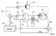
本発明に係る燃料電池コージェネレーションシステムの更なる特徴構成は、回転駆動する通気性吸湿体からなるデシカントロータを有し、そのデシカントロータの吸湿部又は再生部に気体を通流させて空調用空気として空調対象空間に供給するデシカント装置を備え、前記被加熱流体回路は、前記被加熱流体加熱器及び前記凝縮器から排出される被加熱流体を前記デシカント装置における前記デシカントロータの再生に用いるように構成されている点にある。 A further characteristic configuration of the fuel cell cogeneration system according to the present invention includes a desiccant rotor made of a breathable hygroscopic body that is driven to rotate, and air is supplied to the moisture absorbing part or the regenerating part of the desiccant rotor to allow air conditioning air to flow. A desiccant device for supplying air to the air-conditioned space, and the heated fluid circuit uses the heated fluid discharged from the heated fluid heater and the condenser for regeneration of the desiccant rotor in the desiccant device. It is in the point which is comprised.
本特徴構成によれば、被加熱流体回路では、燃料電池装置の排ガスが有する熱を被加熱流体にて回収できるとともに、圧縮式ヒートポンプ装置によっても熱が被加熱流体に与えられるので、それらの熱を有する被加熱流体をデシカントロータの再生に有効に活用することができる。 According to this characteristic configuration, in the heated fluid circuit, the heat of the exhaust gas of the fuel cell device can be recovered by the heated fluid, and heat is also given to the heated fluid by the compression heat pump device. The fluid to be heated can be effectively used for regeneration of the desiccant rotor.
本発明に係る燃料電池コージェネレーションシステムの更なる特徴構成は、前記デシカント装置は、気体に水を噴霧して冷却可能な飽和器と、その飽和器を通過した気体にて前記デシカントロータの前記吸湿部を通過した気体を冷却させる冷却器と、その冷却器を通過した気体を前記被加熱流体回路における被加熱流体が有する熱にて加熱する加熱器と、気体の通流状態を切換自在な通流状態切換手段とを備え、前記通流状態切換手段は、前記デシカントロータの前記吸湿部、前記冷却器の順に第1気体を通過させて空調用空気として空調対象空間に供給し、且つ、前記飽和器、前記冷却器、前記加熱器、前記デシカントロータの前記再生部の順に第2気体を通過させる第1切換状態と、前記飽和器、前記冷却器、前記加熱器、前記デシカントロータの前記再生部の順に第1気体を通過させて空調用空気として空調対象空間に供給し、且つ、前記デシカントロータの前記吸湿部、前記冷却器の順に第2気体を通過させる第2切換状態とに切換自在に構成されている点にある。 The fuel cell cogeneration system according to the present invention is further characterized in that the desiccant device includes a saturator that can be cooled by spraying water on the gas, and the moisture absorption of the desiccant rotor by the gas that has passed through the saturator. A cooler that cools the gas that has passed through the heater, a heater that heats the gas that has passed through the cooler with the heat of the heated fluid in the heated fluid circuit, and a flow that can be switched between gas flow states. Flow state switching means, and the flow state switching means passes the first gas in the order of the hygroscopic portion of the desiccant rotor and the cooler and supplies it as air conditioning air to the air-conditioning target space, and A first switching state in which a second gas is passed in the order of the saturator, the cooler, the heater, and the regeneration portion of the desiccant rotor; and the saturator, the cooler, the heater, and the desiccant. A second switching state in which the first gas is passed in the order of the regeneration part of the rotor and supplied to the air-conditioning target space as air-conditioning air, and the second gas is passed in the order of the moisture absorption part of the desiccant rotor and the cooler. It is in the point that it can be switched to.
本特徴構成によれば、通流状態切換手段が第1切換状態に切り換えることで、第1気体は、デシカントロータの吸湿部にて除湿され、その除湿された第1気体が冷却器にて冷却される。これにより、除湿及び冷却された第1気体を空調用空気として空調対象空間に供給して、空調対象空間の除湿冷房を行うことができる。
通流状態切換手段が第2切換状態に切り換えることで、第1気体は、飽和器にて加湿されて冷却器に供給され、冷却器にて第2気体により加熱される。冷却器を通過した第1気体は、加熱器において更に加熱されて、デシカントロータの再生部に供給される。よって、再生部では、デシカントロータの再生を適切に行うことができながら、第1気体が更に加湿される。このようにして、加湿及び加熱された第1気体を空調用空気として空調対象空間に供給して、空調対象空間の加湿暖房を行うことができる。
このように、通流状態切換手段が第1切換状態と第2切換状態とに切り換えることで、除湿冷媒と加湿暖房とを適切に行うことができながら、加熱器での熱源として被加熱流体を有効に活用することができる。
According to this characteristic configuration, the first gas is dehumidified by the moisture absorption part of the desiccant rotor when the flow state switching means is switched to the first switching state, and the dehumidified first gas is cooled by the cooler. Is done. Thereby, the 1st gas dehumidified and cooled can be supplied to air-conditioning space as air-conditioning air, and dehumidification cooling of the air-conditioning space can be performed.
When the flow state switching means switches to the second switching state, the first gas is humidified by the saturator, supplied to the cooler, and heated by the second gas in the cooler. The 1st gas which passed the cooler is further heated in a heater, and is supplied to the regeneration part of a desiccant rotor. Therefore, in the regeneration unit, the first gas is further humidified while the regeneration of the desiccant rotor can be appropriately performed. In this way, the humidified and heated first gas can be supplied as air-conditioning air to the air-conditioning target space to perform humidification heating of the air-conditioning target space.
As described above, the flow state switching means switches between the first switching state and the second switching state, so that the dehumidified refrigerant and the humidification heating can be appropriately performed, and the fluid to be heated is used as a heat source in the heater. It can be used effectively.
本発明に係る燃料電池コージェネレーションシステムの実施形態を図面に基づいて説明する。
この燃料電池コージェネレーションシステムは、図1に示すように、燃料電池装置1と、冷媒Aを循環する冷媒回路2を備えた圧縮式ヒートポンプ装置3と、燃料電池装置1の排ガスBにて被加熱流体Cを加熱する被加熱流体加熱器4と、その被加熱流体加熱器4から排出される排ガスBを冷却させる排ガス冷却器5と、被加熱流体Cを通流させる被加熱流体回路6と、排ガス冷却器5にて発生される凝縮水を回収して改質水Dとして燃料電池装置1に供給する改質水回収供給手段7とが備えられている。
An embodiment of a fuel cell cogeneration system according to the present invention will be described with reference to the drawings.
As shown in FIG. 1, this fuel cell cogeneration system is heated by a fuel cell device 1, a compression
圧縮式ヒートポンプ装置3は、冷媒回路2にて、冷媒Aを圧縮する圧縮機8、冷媒Aから放熱させる凝縮器9、冷媒Aを膨張させる膨張部10(膨張弁)、冷媒Aに吸熱させる蒸発器11の順に冷媒Aを循環させるように構成されている。この圧縮式ヒートポンプ装置3において、蒸発器11は、外気を吸熱対象流体とする外気用蒸発器11aと排ガスBを吸熱対象流体とする排ガス冷却器5とから構成されている。
The compression
冷媒回路2は、外気用蒸発器11aに冷媒Aを供給する第1分岐部位2aと排ガス冷却器5に冷媒Aを供給する第2分岐部位2bとに分岐されており、外気用蒸発器11aと排ガス冷却器5との両者に冷媒Aを分配して又は一方のみに循環供給自在に構成されている。第1分岐部位2aには、外気用蒸発器11aへの冷媒Aの供給量を調整自在な第1冷媒調整弁12が備えられ、第2分岐部位2bには、排ガス冷却器5への冷媒Aの供給量を調整自在な第2冷媒調整弁13が備えられている。膨張部10(膨張弁)は、第1冷媒調整弁12と第2冷媒調整弁13とから構成されている。
The
被加熱流体回路6は、被加熱流体Cを被加熱流体加熱器4と凝縮器9との両者に分配して又は一方のみに循環供給自在に構成されている。被加熱流体回路6は、被加熱流体Cとしての水や温水等を貯留自在な貯湯タンク14を備えており、その貯湯タンク14と被加熱流体加熱器4及び凝縮器9との間で被加熱流体Cを循環自在に構成されている。そして、被加熱流体回路6は、貯湯タンク14の下部から被加熱流体Cを取り出し、その取り出した被加熱流体Cを被加熱流体加熱器4及び凝縮器9に分配又は一方のみに供給して加熱させ、その加熱された被加熱流体Cを貯湯タンク14の上部に戻すように構成されている。これにより、貯湯タンク14では、高温の被加熱流体Cが上部に且つ低温の被加熱流体Cが下部に位置するように温度成層を形成する状態で被加熱流体Cを貯留するようにしている。
また、被加熱流体回路6は、被加熱流体Cを貯湯タンク14に貯湯させるだけでなく、給湯利用箇所15に被加熱流体Cを供給自在であり、浴槽16での追焚や、デシカント装置17及び床暖房装置18等の熱消費装置にも被加熱流体Cを利用できるように構成されている。
The heated fluid circuit 6 is configured to distribute the heated fluid C to both the
In addition, the heated fluid circuit 6 not only stores the heated fluid C in the hot
このような被加熱流体回路6は、複数の流路部位R1〜R8にて構成されているので、以下、各流路部位について説明する。
第1流路部位R1は、貯湯タンク14の下部と被加熱流体加熱器4とを接続しており、その途中部位に、被加熱流体Cの通流方向で上流側から順に、第1循環ポンプP1、第1流量調整弁19が備えられている。第2流路部位R2は、第1流路部位R1において第1循環ポンプP1の設置箇所と第1流量調整弁19の設置箇所との間の部位と凝縮器9とを接続しており、その途中部位に第2流量調整弁20が備えられている。第3流路部位R3は、被加熱流体加熱器4と貯湯タンク14の上部とを接続するように構成されている。第4流路部位R4は、凝縮器9と第3流路部位R3の途中部位とを接続するように構成されている。
Such a heated fluid circuit 6 is composed of a plurality of flow path portions R1 to R8, and therefore each flow path portion will be described below.
The first flow path part R1 connects the lower part of the hot
第5流路部位R5は、第3流路部位R3において第4流路部位R4との接続箇所と貯湯タンク14の接続箇所との間の部位と給湯利用箇所15とを接続しており、その途中部位に補助給湯器Hが備えられている。第6流路部位R6は、第5流路部位R5において補助給湯器Hの設置箇所と給湯利用箇所15との間の部位と第1流路部位R1において貯湯タンク14の接続箇所と第1循環ポンプP1の設置箇所との間の部位とを接続するように構成されている。第6流路部位R6の途中部位には、被加熱流体Cの通流方向の上流側から順に、第1熱消費熱交換器21、第2循環ポンプP2が備えられている。
The fifth flow path part R5 connects a part between the connection part of the third flow path part R3 and the connection part of the fourth flow path part R4 and the connection part of the hot
第7流路部位R7は、第5流路部位R5において第6流路部位R6の接続箇所と給湯利用箇所15との間の部位と第6流路部位R6において第1熱消費熱交換器21と第2循環ポンプP2との間の部位とを接続するように構成されている。第7流路部位R7の途中部位には、第2熱消費熱交換器22が備えられている。第8流路部位R8は、第6流路部位R6において第2循環ポンプP2の設置箇所と第1流路部位R1の接続箇所との間に被加熱流体C(水道水)を給水するように構成されている。
The seventh flow path part R7 includes the first heat-
第1熱消費熱交換器21には、デシカント装置17との間、及び、床暖房装置18との間で熱媒体Eを循環させる第1循環路23が接続されており、第1熱消費熱交換器21において被加熱流体Cにて加熱された熱媒体Eをデシカント装置17及び床暖房装置18に循環供給自在に構成されている。第1循環路23は、デシカント装置17と床暖房装置18とに熱媒体Eを分配して又は一方にのみ循環供給自在に構成されており、その途中部位に第3循環ポンプP3が備えられている。
A
第2熱消費熱交換器22には、浴槽16との間で浴槽湯水を循環させる第2循環路24が接続されており、第2熱消費熱交換器22において被加熱流体Cにて加熱された浴槽湯水を浴槽16に循環供給自在に構成されている。第2循環路24の途中部位には、第4循環ポンプP4が備えられている。
The second heat
図2に基づいて、燃料電池装置1の構成について説明を加える。図2は、図1において燃料電池装置1の内部構成を示すものであり、被加熱流体回路6の一部を省略して図示している。
燃料電池装置1は、原燃料を改質して燃料ガスを生成する改質器25と、その改質器25で生成された燃料ガスと酸素含有ガス(空気)とが供給されてそれらを発電反応させて発電する燃料電池部26と、その燃料電池部26の排ガスBが供給されてその排ガスBを通流させる排ガス通流部27とが備えられている。
Based on FIG. 2, the configuration of the fuel cell device 1 will be described. FIG. 2 shows the internal configuration of the fuel cell device 1 in FIG. 1, and a part of the heated fluid circuit 6 is omitted.
The fuel cell device 1 is supplied with a
また、燃料電池装置1は、改質器25における改質反応に用いられる水蒸気を生成する水蒸気生成部28と、供給される酸素含有ガス(空気)を予熱する酸素含有ガス予熱器29と、燃料電池部26から排出される排出燃料ガス中の燃料成分と発電反応に用いられた後に排出される排出酸素含有ガスとを混合させて燃焼させる燃焼部30とが備えられている。この燃料電池装置1では、収納容器T内に、水蒸気生成部28、改質器25、燃料電池部26、酸素含有ガス予熱器29が収容されており、燃料電池部26の上方に隣接して配置された燃焼部30にて発生する熱を水蒸気生成部28、改質器25、酸素含有ガス予熱器29にて利用可能に構成されている。
In addition, the fuel cell device 1 includes a
排ガス通流部27は、箱状に形成されており、その内部には、排ガスBの通流方向の上流側から順に、被加熱流体加熱器4、排ガス冷却器5が備えられている。そして、排ガス通流部27は、排ガス冷却器5にて発生される凝縮水を貯留自在に構成されている。改質水回収供給手段7は、排ガス通流部27と、その排ガス通流部27に貯留されている凝縮水を改質器25に供給する凝縮水供給手段31とから構成されている。凝縮水供給手段31は、改質水ポンプ32によって、排ガス通流部27に貯留されている凝縮水を改質水Dとして水蒸気生成部28に供給するように構成されている。
The exhaust
酸素含有ガス予熱器29には、ブロア33によって酸素含有ガス(空気)が給気されるように構成されている。燃料電池部26は、例えば、改質器25で生成された燃料ガスが供給されるアノードと酸素含有ガスが供給されるカソードとを備えた固体酸化物型のセルを複数個電気的に直列接続したセルスタックにて構成されている。そして、燃料電池装置1は、燃料電池部26にて発電された電力をインバータ34によって出力するように構成されている。また、排ガス通流部27には、純水装置35を介して、純水を給水自在に構成されている。
The oxygen-containing
図3及び図4に基づいて、デシカント装置17について説明を加える。
デシカント装置17は、回転駆動する通気性吸湿体からなるデシカントロータ41を有しており、そのデシカントロータ41の吸湿部42又は再生部43に気体を通流させて空調用空気として空調対象空間44に供給するように構成されている。そして、被加熱流体回路6は、図1に示すように、第2熱消費熱交換器22において被加熱流体Cにて加熱された熱媒体Eをデシカント装置17に供給することで、被加熱流体加熱器4及び凝縮器9から排出される被加熱流体Cをデシカント装置17におけるデシカントロータ41の再生に用いるように構成されている。
The
The
デシカント装置17は、気体に水を噴霧して冷却可能な飽和器45と、その飽和器45を通過した気体にてデシカントロータ41の吸湿部42を通過した気体を冷却させる冷却器46と、その冷却器46を通過した気体を被加熱流体Cが有する熱にて加熱する加熱器47と、気体の通流状態を切換自在な通流状態切換手段48とを備えている。加熱器47では、第2熱消費熱交換器22において被加熱流体Cにて加熱された熱媒体Eを供給することで、被加熱流体Cが有する熱にて冷却器46を通過した気体を加熱するように構成されている。冷却器46は、例えば、六角形型の空気熱交換器が用いられている。デシカント装置17は、気体として、外気である第1気体OAと空調対象空間44の空気である第2気体RAとを各機器に通流させており、第1気体OA及び第2気体RAを通流させるための駆動源として第1ファン49と第2ファン50とを備えている。
The
通流状態切換手段48は、第1四方弁51と第2四方弁52を備えている。通流状態切換手段48は、第1四方弁51と第2四方弁52の状態を切り換えることで、第1気体OA及び第2気体RAがどのような順序でどのような機器を通過するかを切り換えている。図3及び図4は、第1気体OA及び第2気体RAの通流状態を示すものであり、通流状態切換手段48は、図3に示す第1切換状態と図4に示す第2切換状態とに切換自在に構成されている。
The flow state switching means 48 includes a first four-
第1切換状態では、図3に示すように、通流状態切換手段48が、第1四方弁51と第2四方弁52を切り換えることで、デシカントロータ41の吸湿部42、冷却器46の順に第1気体OAを通過させて空調用空気として空調対象空間44に供給し、且つ、飽和器45、冷却器46、加熱器47、デシカントロータ41の再生部43の順に第2気体RAを通過させている。第1気体OAは、デシカントロータ41の吸湿部42にて除湿され、その除湿された第1気体OAが冷却器46にて冷却される。これにより、除湿及び冷却された第1気体OAを空調用空気として空調対象空間44に供給して、空調対象空間44の除湿冷房を行うことができる。第2気体RAについては、飽和器45にて冷却されて冷却器46に供給されるので、冷却器46にて第1気体OAを適切に冷却することができる。冷却器46を通過した第2気体RAは、加熱器47において熱媒体Eにて加熱されて、再生部43でのデシカントロータ41の再生を適切に行うことができる。再生部43を通過した第2気体RAは、外部に排気されている。
In the first switching state, as shown in FIG. 3, the flow state switching means 48 switches the first four-
第2切換状態では、図4に示すように、通流状態切換手段48が、第1四方弁51と第2四方弁52を切り換えることで、飽和器45、冷却器46、加熱器47、デシカントロータ41の再生部43の順に第1気体OAを通過させて空調用空気として空調対象空間44に供給し、且つ、デシカントロータ41の吸湿部42、冷却器46の順に第2気体RAを通過させている。第1気体OAは、飽和器45にて加湿されて冷却器46に供給され、冷却器46にて加熱される。冷却器46を通過した第1気体OAは、加熱器47において更に熱媒体Eにて加熱されて、デシカントロータ41の再生部43に供給される。また第1気体OAの温度が、0℃以下の場合は、冷却器46と加熱器47の間に飽和器45なしで水噴霧できるノズルを設けている。よって、再生部43では、デシカントロータ41の再生を適切に行うことができながら、第1気体OAが更に加湿される。このようにして、加湿及び加熱された第1気体OAを空調用空気として空調対象空間44に供給して、空調対象空間44の加湿暖房を行うことができる。第2気体RAについては、デシカントロータ41の吸湿部42にて除湿されて加熱されるので、冷却器46にて第1気体OAを適切に加熱することができる。冷却器46を通過した第2気体RAは、外部に排気されている。
In the second switching state, as shown in FIG. 4, the flow state switching means 48 switches between the first four-
図1に示すように、この燃料電池コージェネレーションシステムには、制御部100が備えられている。この制御部100は、圧縮式ヒートポンプ装置3の運転状態、冷媒回路2における第1冷媒調整弁12及び第2冷媒調整弁13の開閉状態、被加熱流体回路6における第1流量調整弁19及び第2流量調整弁20の開閉状態、被加熱流体回路6における第1〜第4循環ポンプP1〜P4の作動状態等を制御するように構成されている。また、図示は省略するが、燃料電池装置1、デシカント装置17、床暖房装置18、風呂装置等の各種の装置には、その装置の運転を制御する運転制御部が備えられている。そして、これらの運転制御部と制御部100とが通信を行うことにより、制御部100は、どの装置から運転要求があるか等の運転状況を把握するように構成されている。
As shown in FIG. 1, the fuel cell cogeneration system includes a control unit 100. The control unit 100 includes an operation state of the compression
ここで、被加熱流体供給量調整手段101は、第1流量調整弁19、第2流量調整弁20、及び、制御部100から構成されている。冷媒供給量調整手段102は、第1冷媒調整弁12、第2冷媒調整弁13、及び、制御部100から構成されている。
Here, the heated fluid supply amount adjusting means 101 includes a first flow
制御部100は、第1循環ポンプP1を作動させることで、貯湯タンク14の下部から取り出した被加熱流体Cを被加熱流体加熱器4に供給して加熱し、その加熱された被加熱流体Cを貯湯タンク14の上部に供給して、貯湯タンク14への貯湯を行うようにしている。この場合に、制御部100は、圧縮式ヒートポンプ装置3を運転させることで、被加熱流体加熱器4に加えて、凝縮器9にも被加熱流体Cを供給して加熱することができる。そして、制御部100は、被加熱流体加熱器4にて加熱された被加熱流体Cと凝縮器9にて加熱された被加熱流体Cとを合流させて、合流後の被加熱流体Cを貯湯タンク14の上部に供給している。
The control unit 100 operates the first circulation pump P1 to supply the heated fluid C taken out from the lower part of the hot
また、被加熱流体加熱器4や凝縮器9にて加熱された被加熱流体Cの供給先としては、貯湯タンク14だけでなく、第1熱消費熱交換器21及び第2熱消費熱交換器22にも被加熱流体Cを供給することができる。そして、制御部100は、デシカント装置17や床暖房装置18から運転要求がある場合には、被加熱流体加熱器4や凝縮器9にて加熱された被加熱流体Cを第1熱消費熱交換器21に供給しており、風呂装置にて追焚要求がある場合には、被加熱流体加熱器4や凝縮器9にて加熱された被加熱流体Cを第2熱消費熱交換器22に供給している。第1熱消費熱交換器21及び第2熱消費熱交換器22に対しては、被加熱流体加熱器4や凝縮器9にて加熱された被加熱流体Cだけでなく、被加熱流体加熱器4や凝縮器9にて加熱された被加熱流体Cと貯湯タンク14の上部の被加熱流体Cとを混合させて、その混合後の被加熱流体Cを供給できるようになっている。
Further, the supply destination of the heated fluid C heated by the
給湯利用箇所15に対しては、貯湯タンク14に貯湯されている被加熱流体Cを供給自在に構成されている。被加熱流体Cの温度が給湯利用箇所15にて要求されている温度よりも低い場合には、補助給湯器Hにて加熱された被加熱流体Cを給湯利用箇所15に供給するようにしている。また、給湯利用箇所15に対しては、貯湯タンク14に貯湯されている被加熱流体Cだけでなく、被加熱流体加熱器4や凝縮器9にて加熱された被加熱流体Cと貯湯タンク14の上部の被加熱流体Cとを混合させて、その混合後の被加熱流体Cを供給できるようになっている。
The hot
制御部100は、要求されている熱需要がヒートポンプ運転可否用の設定熱需要よりも少ない場合に圧縮式ヒートポンプ装置3を運転させず、要求されている熱需要がヒートポンプ運転可否用の設定熱需要よりも多い場合に圧縮式ヒートポンプ装置3を運転させるように構成されている。そして、要求されている熱需要の大きさについては、例えば、制御部100が、貯湯タンク14の貯湯量がどれぐらいか、給湯利用箇所15での給湯需要があるか否か及びその給湯需要の大きさ、デシカント装置17から運転要求があるか否か及びその要求熱量の大きさ、床暖房装置18から運転要求があるか否か及びその要求熱量の大きさ、浴槽16での追焚運転の要求があるか否か及びその要求熱量の大きさに基づいて求めることができる。
The controller 100 does not operate the compression
制御部100は、図5に示すように、圧縮式ヒートポンプ装置3を運転させない場合には、被加熱流体回路6において、凝縮器9への被加熱流体Cの供給量をゼロとし、且つ、排ガス冷却器5にて発生する凝縮水の発生量が設定量に達するための第1条件を満たすように、被加熱流体加熱器4への被加熱流体Cの供給量を調整する第1供給量調整運転を行うように構成されている。図5では、流体が通流する部位を太線にて示しており、熱の供給先としては貯湯タンク14に貯湯する場合を示している。この第1供給量調整運転では、制御部100が、第2流量調整弁20を閉状態とし、第1条件を満たすように第1流量調整弁19の開度を調整している。ここで、第1条件は、排ガス冷却器5を通過した排ガスBの温度が設定温度以下となる条件、又は、排ガス冷却器5にて発生する凝縮水の発生量が設定量以上となる条件となっている。
As shown in FIG. 5, when the compression
このように、圧縮式ヒートポンプ装置3を運転させない場合には、被加熱流体Cを被加熱流体加熱器4のみに供給しており、被加熱流体加熱器4にて加熱された被加熱流体Cを貯湯タンク14や第1熱消費熱交換器21等に供給している。そして、燃料電池装置1の排ガスBは、被加熱流体加熱器4にて冷却されて凝縮水を発生するので、改質水回収供給手段7が、その凝縮水を改質水Dとして燃料電池装置1に供給している。
Thus, when the compression
制御部100は、図6に示すように、圧縮式ヒートポンプ装置3を運転させる場合には、冷媒回路2において、圧縮機8に戻る冷媒Aの過熱度が設定過熱度になるように、第1冷媒調整弁12及び第2冷媒調整弁13の開度を調整する冷媒供給量調整運転を行うように構成されている。図6では、流体が通流する部位を太線にて示しており、熱の供給先としては貯湯タンク14に貯湯する場合を示している。制御部100は、その冷媒供給量調整運転に加えて、被加熱流体回路6において、凝縮器9から排出される被加熱流体Cの温度を第1設定温度(例えば、75℃)とするように、第2流量調整弁20の開度を調整し、且つ、排ガス冷却器5にて発生する凝縮水の発生量が設定量に達するとともに、凝縮器9から排出される被加熱流体Cと被加熱流体加熱器4から排出される被加熱流体Cの合流温度を第1設定温度とするように、第1流量調整弁19の開度を調整する第2供給量調整運転を行うように構成されている。
As shown in FIG. 6, when operating the compression
このように、圧縮式ヒートポンプ装置3を運転させる場合には、被加熱流体Cを被加熱流体加熱器4と凝縮器9の両者に供給しており、被加熱流体加熱器4にて加熱された被加熱流体Cと凝縮器9にて加熱された被加熱流体Cとを合流させて、その合流後の被加熱流体Cを貯湯タンク14や第1熱消費熱交換器21等に供給している。そして、燃料電池装置1の排ガスBは、被加熱流体加熱器4にて冷却され、更に、排ガス冷却器5にて冷却される。これにより、被加熱流体加熱器4に供給する被加熱流体Cの温度が比較的高温であっても、凝縮水を適切に発生させることができ、改質水回収供給手段7が、その凝縮水を改質水Dとして燃料電池装置1に供給している。
As described above, when the compression
制御部100は、圧縮式ヒートポンプ装置3を運転させる場合に、冷媒回路2についての冷媒供給量調整運転において、排ガス冷却器5への冷媒Aの供給量を増加させ且つ外気用蒸発器11aへの冷媒Aの供給量を減少させるように、第1冷媒調整弁12及び第2冷媒調整弁13の開度を調整自在に構成されている。
When operating the compression
本発明は、燃料電池装置の排熱にて被加熱流体を加熱し、その加熱された被加熱流体を熱利用箇所に供給自在に構成され、水自立を成立させることができ、エネルギー効率の向上を図りながら、熱需要に合わせた熱供給を行うことができる各種の燃料電池コージェネレーションシステムに適応可能である。 The present invention heats a fluid to be heated by exhaust heat of the fuel cell device, and can supply the heated fluid to be heated to a place where heat is used, so that water self-sustainment can be established and energy efficiency is improved. It is applicable to various fuel cell cogeneration systems that can supply heat according to heat demand.
1 燃料電池装置
2 冷媒回路
3 圧縮式ヒートポンプ装置
4 被加熱流体加熱器
5 排ガス冷却器
6 被加熱流体回路
7 改質水回収供給手段
8 圧縮機
9 凝縮器
10 膨張部
11 蒸発器
11a 外気用蒸発器
17 デシカント装置
25 改質器
26 燃料電池部
27 排ガス通流部
31 凝縮水供給手段
41 デシカントロータ
42 吸湿部
43 再生部
44 空調対象空間
45 飽和器
46 冷却器
47 加熱器
48 通流状態切換手段
101 被加熱流体供給量調整手段
102 冷媒供給量調整手段
DESCRIPTION OF SYMBOLS 1
Claims (5)
燃料電池装置の排ガスにて被加熱流体を加熱する被加熱流体加熱器と、
その被加熱流体加熱器から排出される排ガスを冷却させる排ガス冷却器と、
その排ガス冷却器にて発生される凝縮水を回収して改質水として前記燃料電池装置に供給する改質水回収供給手段と、
冷媒の放熱対象流体として前記凝縮器に被加熱流体を循環供給自在であり、且つ、前記凝縮器と前記被加熱流体加熱器との両者に被加熱流体を分配して又は一方のみに循環供給自在な被加熱流体回路とを備え、
前記蒸発器は、外気を吸熱対象流体とする外気用蒸発器と排ガスを吸熱対象流体とする前記排ガス冷却器とから構成され、
前記冷媒回路は、前記外気用蒸発器と前記排ガス冷却器との両者に冷媒を分配して又は一方のみに循環供給自在に構成され、
前記被加熱流体回路は、前記被加熱流体加熱器及び前記凝縮器への被加熱流体の供給量を調整自在な被加熱流体供給量調整手段を備え、前記冷媒回路は、前記外気用蒸発器及び前記排ガス冷却器への冷媒の供給量を調整自在な冷媒供給量調整手段を備え、
前記圧縮式ヒートポンプ装置を運転させない場合には、前記被加熱流体供給量調整手段が、前記凝縮器への被加熱流体の供給量をゼロとし、且つ、前記排ガス冷却器にて発生する凝縮水の発生量が設定量に達するための第1条件を満たすように、前記被加熱流体加熱器への被加熱流体の供給量を調整する第1供給量調整運転を実行可能であり、
前記圧縮式ヒートポンプ装置を運転させる場合には、前記冷媒供給量調整手段が、前記圧縮機に戻る冷媒の過熱度が設定過熱度になるように、前記外気用蒸発器及び前記排ガス冷却器の両者への冷媒の供給量を調整する冷媒供給量調整運転を実行可能であり、且つ、前記被加熱流体供給量調整手段が、前記凝縮器から排出される被加熱流体の温度を第1設定温度とし、且つ、前記排ガス冷却器にて発生する凝縮水の発生量が設定量に達するとともに、前記凝縮器から排出される被加熱流体と前記被加熱流体加熱器から排出される被加熱流体の合流温度を第1設定温度とするように、前記被加熱流体加熱器及び前記凝縮器の両者への被加熱流体の供給量を調整する第2供給量調整運転を実行可能である燃料電池コージェネレーションシステム。 A compressor that compresses the refrigerant, a condenser that dissipates heat from the refrigerant, an expansion unit that expands the refrigerant, and a compression heat pump device that includes a refrigerant circuit that circulates the refrigerant in the order of the evaporator that absorbs heat from the refrigerant;
A heated fluid heater for heating the heated fluid with the exhaust gas of the fuel cell device;
An exhaust gas cooler for cooling the exhaust gas discharged from the heated fluid heater;
Reformed water recovery and supply means for recovering condensed water generated in the exhaust gas cooler and supplying the condensed water to the fuel cell device as reformed water;
The fluid to be heated can be circulated and supplied to the condenser as a refrigerant heat release target fluid, and the fluid to be heated can be distributed to both the condenser and the heated fluid heater or circulated and supplied to only one of them. A heated fluid circuit,
The evaporator is composed of an outside air evaporator that uses outside air as the endothermic fluid and the exhaust gas cooler that uses exhaust gas as the endothermic fluid.
The refrigerant circuit is configured to distribute the refrigerant to both the outside air evaporator and the exhaust gas cooler, or to circulate and supply only to one of the refrigerant circuit ,
The heated fluid circuit includes a heated fluid supply amount adjusting means capable of adjusting a supply amount of the heated fluid to the heated fluid heater and the condenser, and the refrigerant circuit includes the outside air evaporator and A refrigerant supply amount adjusting means capable of adjusting a supply amount of the refrigerant to the exhaust gas cooler;
When the compression heat pump device is not operated, the heated fluid supply amount adjusting means sets the supply amount of the heated fluid to the condenser to zero and the condensed water generated in the exhaust gas cooler. A first supply amount adjustment operation of adjusting a supply amount of the heated fluid to the heated fluid heater so as to satisfy a first condition for the generated amount to reach a set amount;
When operating the compression heat pump device, the refrigerant supply amount adjusting means is configured so that both of the outside-air evaporator and the exhaust gas cooler are set so that the superheat degree of the refrigerant returning to the compressor becomes a set superheat degree. The refrigerant supply amount adjustment operation for adjusting the refrigerant supply amount to the refrigerant can be executed, and the heated fluid supply amount adjusting means sets the temperature of the heated fluid discharged from the condenser as the first set temperature. In addition, when the amount of condensed water generated in the exhaust gas cooler reaches a set amount, the combined temperature of the heated fluid discharged from the condenser and the heated fluid discharged from the heated fluid heater Is a fuel cell cogeneration system capable of performing a second supply amount adjustment operation for adjusting the supply amount of the heated fluid to both the heated fluid heater and the condenser so as to be the first set temperature .
前記排ガス通流部の内部には、排ガスの通流方向の上流側から順に、前記被加熱流体加熱器、前記排ガス冷却器が備えられ、前記改質水回収供給手段は、前記排ガス冷却器にて発生される凝縮水を貯留自在な前記排ガス通流部と、その排ガス通流部に貯留されている凝縮水を前記改質器に供給する凝縮水供給手段とから構成されている請求項1に記載の燃料電池コージェネレーションシステム。 The fuel cell device supplies a reformer that reforms a raw fuel to generate a fuel gas, and a fuel gas and an oxygen-containing gas generated by the reformer and generates a power by reacting them. A fuel cell unit, and an exhaust gas flow part to which the exhaust gas of the fuel cell part is supplied to flow the exhaust gas,
In the exhaust gas flow section, the heated fluid heater and the exhaust gas cooler are provided in order from the upstream side in the exhaust gas flow direction, and the reformed water recovery supply means is provided in the exhaust gas cooler. 2. The exhaust gas flow portion that can store the condensed water that is generated in this way, and condensed water supply means that supplies the reformed water stored in the exhaust gas flow portion to the reformer. The fuel cell cogeneration system described in 1.
Priority Applications (1)
| Application Number | Priority Date | Filing Date | Title |
|---|---|---|---|
| JP2012158866A JP5980025B2 (en) | 2012-07-17 | 2012-07-17 | Fuel cell cogeneration system |
Applications Claiming Priority (1)
| Application Number | Priority Date | Filing Date | Title |
|---|---|---|---|
| JP2012158866A JP5980025B2 (en) | 2012-07-17 | 2012-07-17 | Fuel cell cogeneration system |
Publications (2)
| Publication Number | Publication Date |
|---|---|
| JP2014020651A JP2014020651A (en) | 2014-02-03 |
| JP5980025B2 true JP5980025B2 (en) | 2016-08-31 |
Family
ID=50195745
Family Applications (1)
| Application Number | Title | Priority Date | Filing Date |
|---|---|---|---|
| JP2012158866A Expired - Fee Related JP5980025B2 (en) | 2012-07-17 | 2012-07-17 | Fuel cell cogeneration system |
Country Status (1)
| Country | Link |
|---|---|
| JP (1) | JP5980025B2 (en) |
Families Citing this family (7)
| Publication number | Priority date | Publication date | Assignee | Title |
|---|---|---|---|---|
| JP2017506735A (en) | 2014-02-16 | 2017-03-09 | ビー パワー テク,インコーポレイテッド | Liquid desiccant regeneration system and operation method thereof |
| JP6317154B2 (en) * | 2014-03-26 | 2018-04-25 | 大和ハウス工業株式会社 | Hot water system |
| JP6452368B2 (en) * | 2014-09-25 | 2019-01-16 | 大阪瓦斯株式会社 | Fuel cell equipment type air conditioning system |
| JP2016072054A (en) * | 2014-09-30 | 2016-05-09 | アイシン精機株式会社 | Fuel cell module and fuel cell system |
| JP6186530B1 (en) * | 2017-03-28 | 2017-08-23 | 東京瓦斯株式会社 | Fuel cell system, control device, and program |
| KR102280852B1 (en) * | 2020-07-06 | 2021-07-23 | 주식회사 뉴비전네트웍스 | Spatial image drawing system that improves the precision of drawing |
| CN113540511B (en) * | 2021-07-16 | 2024-03-01 | 陕西氢易能源科技有限公司 | Organic liquid integrated energy system with high-efficiency heat recovery |
Family Cites Families (5)
| Publication number | Priority date | Publication date | Assignee | Title |
|---|---|---|---|---|
| JP2003227627A (en) * | 2002-02-05 | 2003-08-15 | Daikin Ind Ltd | Cogeneration system |
| JP4178446B2 (en) * | 2002-09-13 | 2008-11-12 | 三菱電機株式会社 | Heat pump system |
| JP4348531B2 (en) * | 2004-01-30 | 2009-10-21 | 株式会社西部技研 | Dehumidifying air conditioner |
| JP5457818B2 (en) * | 2009-12-21 | 2014-04-02 | パナソニック株式会社 | Cogeneration system |
| JP5503372B2 (en) * | 2010-03-30 | 2014-05-28 | 大阪瓦斯株式会社 | Fuel cell cogeneration system |
-
2012
- 2012-07-17 JP JP2012158866A patent/JP5980025B2/en not_active Expired - Fee Related
Also Published As
| Publication number | Publication date |
|---|---|
| JP2014020651A (en) | 2014-02-03 |
Similar Documents
| Publication | Publication Date | Title |
|---|---|---|
| JP5980025B2 (en) | Fuel cell cogeneration system | |
| KR101843380B1 (en) | Cooling and heating device | |
| JP2021000971A (en) | Heat pump system for vehicle | |
| JP4341356B2 (en) | Fuel cell system | |
| JP2015022864A (en) | Fuel cell system | |
| JP2009036473A (en) | Fuel cell system | |
| JP2004211979A (en) | Absorption refrigerating system | |
| JP3823439B2 (en) | Fuel cell drive air conditioning system | |
| JP4007442B2 (en) | Air conditioning system using exhaust heat of fuel cells | |
| WO2012153484A1 (en) | Fuel cell system and method for operating same | |
| JP2014182923A (en) | Fuel cell system and operation method thereof | |
| JP2018006016A (en) | Fuel cell system | |
| JP2000030726A (en) | Solid polymer fuel cell system | |
| JP2011131858A (en) | Air-conditioning system having fuel cell, air-conditioning method using fuel cell, and fuel cell vehicle having air-conditioning system | |
| JPH085190A (en) | Fuel battery-driven air conditioner | |
| JP7249172B2 (en) | A heat supply device that heats a fluid | |
| KR100638225B1 (en) | Cogeneration system and its control method | |
| JP2004100990A (en) | Cogeneration system | |
| WO2021064605A1 (en) | Sofc vehicle cooling structure and sofc vehicle | |
| JP2005259440A (en) | Fuel cell system | |
| JP4791661B2 (en) | Polymer electrolyte fuel cell system | |
| JP4660933B2 (en) | Fuel cell driven heat pump device | |
| JP2009170189A (en) | Fuel cell system and method of recovering flocculated water in the fuel cell system | |
| JP2019168180A (en) | Water cooler/heater combined type fuel cell system | |
| JP2015121370A (en) | Cogeneration System |
Legal Events
| Date | Code | Title | Description |
|---|---|---|---|
| A621 | Written request for application examination |
Free format text: JAPANESE INTERMEDIATE CODE: A621 Effective date: 20150612 |
|
| A521 | Written amendment |
Free format text: JAPANESE INTERMEDIATE CODE: A821 Effective date: 20150612 |
|
| A977 | Report on retrieval |
Free format text: JAPANESE INTERMEDIATE CODE: A971007 Effective date: 20160317 |
|
| A131 | Notification of reasons for refusal |
Free format text: JAPANESE INTERMEDIATE CODE: A131 Effective date: 20160405 |
|
| A521 | Written amendment |
Free format text: JAPANESE INTERMEDIATE CODE: A523 Effective date: 20160602 |
|
| TRDD | Decision of grant or rejection written | ||
| A01 | Written decision to grant a patent or to grant a registration (utility model) |
Free format text: JAPANESE INTERMEDIATE CODE: A01 Effective date: 20160628 |
|
| A61 | First payment of annual fees (during grant procedure) |
Free format text: JAPANESE INTERMEDIATE CODE: A61 Effective date: 20160726 |
|
| R150 | Certificate of patent or registration of utility model |
Ref document number: 5980025 Country of ref document: JP Free format text: JAPANESE INTERMEDIATE CODE: R150 |
|
| LAPS | Cancellation because of no payment of annual fees |