JP5974987B2 - Head-up display device and lighting device used for head-up display device - Google Patents
Head-up display device and lighting device used for head-up display device Download PDFInfo
- Publication number
- JP5974987B2 JP5974987B2 JP2013130061A JP2013130061A JP5974987B2 JP 5974987 B2 JP5974987 B2 JP 5974987B2 JP 2013130061 A JP2013130061 A JP 2013130061A JP 2013130061 A JP2013130061 A JP 2013130061A JP 5974987 B2 JP5974987 B2 JP 5974987B2
- Authority
- JP
- Japan
- Prior art keywords
- image
- light
- head
- display device
- light pipe
- Prior art date
- Legal status (The legal status is an assumption and is not a legal conclusion. Google has not performed a legal analysis and makes no representation as to the accuracy of the status listed.)
- Active
Links
- 230000003287 optical effect Effects 0.000 claims description 40
- 238000005286 illumination Methods 0.000 claims description 31
- 210000001747 pupil Anatomy 0.000 claims description 28
- 238000009792 diffusion process Methods 0.000 claims description 13
- 230000002093 peripheral effect Effects 0.000 claims description 11
- 238000002834 transmittance Methods 0.000 claims description 2
- 239000004973 liquid crystal related substance Substances 0.000 description 11
- 239000003086 colorant Substances 0.000 description 5
- 230000000694 effects Effects 0.000 description 5
- 230000004048 modification Effects 0.000 description 4
- 238000012986 modification Methods 0.000 description 4
- 239000011521 glass Substances 0.000 description 3
- 238000000034 method Methods 0.000 description 3
- 239000012780 transparent material Substances 0.000 description 3
- 230000001678 irradiating effect Effects 0.000 description 2
- 239000011159 matrix material Substances 0.000 description 2
- 239000004925 Acrylic resin Substances 0.000 description 1
- 229920000178 Acrylic resin Polymers 0.000 description 1
- NIXOWILDQLNWCW-UHFFFAOYSA-N acrylic acid group Chemical group C(C=C)(=O)O NIXOWILDQLNWCW-UHFFFAOYSA-N 0.000 description 1
- 230000002411 adverse Effects 0.000 description 1
- 238000005452 bending Methods 0.000 description 1
- 230000015572 biosynthetic process Effects 0.000 description 1
- 238000004364 calculation method Methods 0.000 description 1
- 238000005516 engineering process Methods 0.000 description 1
- 239000010419 fine particle Substances 0.000 description 1
- 230000017525 heat dissipation Effects 0.000 description 1
- 238000004519 manufacturing process Methods 0.000 description 1
- 239000002184 metal Substances 0.000 description 1
- 229920003229 poly(methyl methacrylate) Polymers 0.000 description 1
- 239000004926 polymethyl methacrylate Substances 0.000 description 1
- 230000001502 supplementing effect Effects 0.000 description 1
- 230000003313 weakening effect Effects 0.000 description 1
Images


Classifications
-
- G—PHYSICS
- G02—OPTICS
- G02B—OPTICAL ELEMENTS, SYSTEMS OR APPARATUS
- G02B27/00—Optical systems or apparatus not provided for by any of the groups G02B1/00 - G02B26/00, G02B30/00
- G02B27/01—Head-up displays
- G02B27/0101—Head-up displays characterised by optical features
-
- G—PHYSICS
- G02—OPTICS
- G02B—OPTICAL ELEMENTS, SYSTEMS OR APPARATUS
- G02B27/00—Optical systems or apparatus not provided for by any of the groups G02B1/00 - G02B26/00, G02B30/00
- G02B27/01—Head-up displays
-
- B—PERFORMING OPERATIONS; TRANSPORTING
- B60—VEHICLES IN GENERAL
- B60K—ARRANGEMENT OR MOUNTING OF PROPULSION UNITS OR OF TRANSMISSIONS IN VEHICLES; ARRANGEMENT OR MOUNTING OF PLURAL DIVERSE PRIME-MOVERS IN VEHICLES; AUXILIARY DRIVES FOR VEHICLES; INSTRUMENTATION OR DASHBOARDS FOR VEHICLES; ARRANGEMENTS IN CONNECTION WITH COOLING, AIR INTAKE, GAS EXHAUST OR FUEL SUPPLY OF PROPULSION UNITS IN VEHICLES
- B60K35/00—Instruments specially adapted for vehicles; Arrangement of instruments in or on vehicles
-
- G—PHYSICS
- G02—OPTICS
- G02B—OPTICAL ELEMENTS, SYSTEMS OR APPARATUS
- G02B3/00—Simple or compound lenses
- G02B3/0006—Arrays
-
- G—PHYSICS
- G02—OPTICS
- G02B—OPTICAL ELEMENTS, SYSTEMS OR APPARATUS
- G02B5/00—Optical elements other than lenses
- G02B5/02—Diffusing elements; Afocal elements
-
- G—PHYSICS
- G02—OPTICS
- G02B—OPTICAL ELEMENTS, SYSTEMS OR APPARATUS
- G02B5/00—Optical elements other than lenses
- G02B5/08—Mirrors
- G02B5/10—Mirrors with curved faces
-
- G—PHYSICS
- G02—OPTICS
- G02B—OPTICAL ELEMENTS, SYSTEMS OR APPARATUS
- G02B6/00—Light guides; Structural details of arrangements comprising light guides and other optical elements, e.g. couplings
- G02B6/0001—Light guides; Structural details of arrangements comprising light guides and other optical elements, e.g. couplings specially adapted for lighting devices or systems
- G02B6/0096—Light guides; Structural details of arrangements comprising light guides and other optical elements, e.g. couplings specially adapted for lighting devices or systems the lights guides being of the hollow type
-
- G—PHYSICS
- G02—OPTICS
- G02B—OPTICAL ELEMENTS, SYSTEMS OR APPARATUS
- G02B27/00—Optical systems or apparatus not provided for by any of the groups G02B1/00 - G02B26/00, G02B30/00
- G02B27/01—Head-up displays
- G02B27/0101—Head-up displays characterised by optical features
- G02B2027/0118—Head-up displays characterised by optical features comprising devices for improving the contrast of the display / brillance control visibility
-
- G—PHYSICS
- G02—OPTICS
- G02B—OPTICAL ELEMENTS, SYSTEMS OR APPARATUS
- G02B27/00—Optical systems or apparatus not provided for by any of the groups G02B1/00 - G02B26/00, G02B30/00
- G02B27/01—Head-up displays
- G02B27/0101—Head-up displays characterised by optical features
- G02B2027/0123—Head-up displays characterised by optical features comprising devices increasing the field of view
Landscapes
- Physics & Mathematics (AREA)
- General Physics & Mathematics (AREA)
- Optics & Photonics (AREA)
- Engineering & Computer Science (AREA)
- Chemical & Material Sciences (AREA)
- Combustion & Propulsion (AREA)
- Transportation (AREA)
- Mechanical Engineering (AREA)
- Instrument Panels (AREA)
Description
本発明は、運転席の前方に設けられた透明な板状部材に画像を投影することによって、運転席の前方の景色に重ねて画像を虚像表示するヘッドアップディスプレイ装置、およびヘッドアップディスプレイ装置に用いられる照明装置に関する。 The present invention relates to a head-up display device and a head-up display device that project an image onto a transparent plate-like member provided in front of the driver's seat and display a virtual image on the scenery in front of the driver's seat. The present invention relates to a lighting device used.
運転席に前方に設けられた透明な板状部材(コンバイナーやウィンドシールドなど)に画像を投影することによって、運転席の前方の景色に重ねて画像を虚像表示するヘッドアップディスプレイ装置(以下、HUD装置)が知られている。HUD装置は、投影しようとする画像を液晶画面などに表示して、背面側から光を照射することによって画像を投影する。 A head-up display device (hereinafter referred to as HUD) that displays a virtual image over the scenery in front of the driver seat by projecting the image onto a transparent plate-like member (combiner, windshield, etc.) provided in front of the driver seat. Device) is known. The HUD device displays an image to be projected on a liquid crystal screen or the like, and projects the image by irradiating light from the back side.
このHUD装置では、好天時であっても、前方の景色に重ねて表示された画像が鮮明に視認できる必要があるため、十分な高い輝度で画像を虚像表示可能なことが要請されている。この要請に応えるためには、液晶画面などを背面側から照射する光源の輝度を増加させればよいが、そうすると光源の放熱量が増加したり、光源を収容するために大きなスペースが必要になったりする。 In this HUD device, even when the weather is fine, it is necessary to be able to clearly see the image displayed superimposed on the scenery in front, so that it is required to display a virtual image with sufficiently high luminance. . In order to meet this requirement, the luminance of the light source that irradiates the liquid crystal screen or the like from the back side may be increased. However, this increases the heat dissipation amount of the light source or requires a large space to accommodate the light source. Or
そこで、通常は赤色の画素、緑色の画素、青色の画素の3種類の画素で構成されている液晶画面を、赤色の画素および緑色の画素の2種類の画素で構成する技術が提案されている(特許文献1)。こうすれば、単位面積あたりの液晶画面で発光する画素の密度を高めることができるので、光源の輝度を上げなくても、虚像表示された画像の輝度を高めることが可能となる。 In view of this, a technique has been proposed in which a liquid crystal screen, which is usually composed of three types of pixels, a red pixel, a green pixel, and a blue pixel, is composed of two types of pixels, a red pixel and a green pixel. (Patent Document 1). In this way, since the density of pixels that emit light on the liquid crystal screen per unit area can be increased, it is possible to increase the luminance of an image displayed as a virtual image without increasing the luminance of the light source.
しかし、提案されている技術では、液晶画面上に青色の画素が存在しないので、表示可能な色が制限されるという問題がある。すなわち、光の三原色に対応する赤色、緑色、青色を表示することができれば、これらを混色することによって実用上の全ての色を表示することが可能となるが、青色が表示することができないので、表示可能な色が大幅に制限されてしまうという問題があった。 However, the proposed technique has a problem in that displayable colors are limited because there are no blue pixels on the liquid crystal screen. That is, if red, green, and blue corresponding to the three primary colors of light can be displayed, it is possible to display all practical colors by mixing them, but blue cannot be displayed. There is a problem that displayable colors are greatly limited.
この発明は、上述した問題に鑑みてなされたものであり、光源の輝度を上げたり、表示可能な色数を減らしたりすることなく、HUD装置で高い輝度の画像を虚像表示することが可能な技術の提供を目的とする。 The present invention has been made in view of the above-described problems, and it is possible to display a high-luminance image with a HUD device without increasing the luminance of a light source or reducing the number of colors that can be displayed. The purpose is to provide technology.
上述した問題を解決するために本発明のヘッドアップディスプレイ装置および照明装置は、運転者に対して表示しようとする画像を画像表示部に表示する。そして、表示した画像を照明することによって、その画像を、少なくとも1つの凹面鏡要素を有する表示光学系を用いて、運転者に虚像表示する。ここで、画像表示部と、画像表示部に表示された画像を照明するための光を放出する光放出面との間には、アイボックスの表示光学系による入射瞳を光放出面上に分割して結像させるレンズアレイが配置されている。
尚、光放出面は、光を放出する面であれば足り、光を発光する発光面とすることもできるし、内部からの光を透過させる透過面とすることもできるし、更には光を拡散させる拡散面とすることもできる。
In order to solve the above-described problem, the head-up display device and the lighting device of the present invention display an image to be displayed to the driver on the image display unit . Their to, by illuminating the image display, the image, using a display optical system having at least one concave mirror elements, to virtual image displays to the driver. Here, the entrance pupil by the display optical system of the eye box is divided on the light emission surface between the image display unit and the light emission surface that emits light for illuminating the image displayed on the image display unit. A lens array for image formation is arranged.
The light emitting surface may be a surface that emits light, may be a light emitting surface that emits light, may be a transmitting surface that transmits light from the inside, and may further transmit light. It can also be a diffusion surface to diffuse.
レンズアレイは、複数の小レンズから構成されているので焦点距離を短くすることができ、尚且つ、レンズアレイ全体では大きなレンズ径を実現することができる。このため、画像表示部と光放出面との距離が短い場合でも、光放出面からの光を効率よく集光して、画像表示部の画像全体を照明することができるので、高い輝度の画像を虚像表示することが可能となる。加えて、光放出面とアイボックスとが、レンズアレイおよび表示光学系を介して共役な関係となるので、光放出面からレンズアレイに向けて放出された光が必ずアイボックスに到達する。このため、光放出面から放出された光を効率よく利用することができるので、高い輝度の画像を虚像表示することが可能となる。
尚、レンズアレイは、複数の小レンズが列状にあるいは面状に配置されていれば良く、従って、複数の小レンズは、一体に形成されていてもよいし、別体に形成された複数の小レンズを配置することによって、レンズアレイを形成しても良い。
また、凹面鏡要素としては、いわゆる凹面鏡を用いることもできるし、透明な材料によって形成されて、斜め方向から投影された光を反射するいわゆるコンバイナーを用いることもできる。
Since the lens array is composed of a plurality of small lenses, the focal length can be shortened, and a large lens diameter can be realized in the entire lens array. For this reason, even when the distance between the image display unit and the light emission surface is short, light from the light emission surface can be efficiently collected and the entire image on the image display unit can be illuminated, so that a high-luminance image can be obtained. Can be displayed as a virtual image. In addition, since the light emission surface and the eye box have a conjugate relationship via the lens array and the display optical system, light emitted from the light emission surface toward the lens array always reaches the eye box. For this reason, since the light emitted from the light emitting surface can be used efficiently, a high-luminance image can be displayed as a virtual image.
The lens array only needs to have a plurality of small lenses arranged in a line or a plane. Therefore, the plurality of small lenses may be formed integrally or a plurality of small lenses formed separately. A lens array may be formed by arranging the small lenses.
As the concave mirror element, a so-called concave mirror can be used, or a so-called combiner that is formed of a transparent material and reflects light projected from an oblique direction can be used.
また、上述した本発明のヘッドアップディスプレイ装置においては、運転者の前方に設けられた透明な板状部材に、凹面鏡を用いて画像を投影することによって、投影した画像を虚像表示することとしてもよい。 In the head-up display device of the present invention described above, the projected image may be displayed as a virtual image by projecting the image onto the transparent plate member provided in front of the driver using a concave mirror. Good.
こうすれば、車両のウィンドシールドに画像を投影することができるので、大きな画像を虚像表示することができる。そして、本発明のヘッドアップディスプレイ装置では、高輝度の画像を表示することができるので、表示する画像が大きくなっても、十分な輝度を確保することが可能となる。 In this way, an image can be projected onto the windshield of the vehicle, so that a large image can be displayed as a virtual image. In the head-up display device of the present invention, a high-luminance image can be displayed, so that sufficient luminance can be ensured even when the displayed image becomes large.
また、上述した本発明のヘッドアップディスプレイ装置においては、光の透過率を変更することによって画像を表示する透過型の画像表示部の背面側から、画像を照明することとしてもよい。 In the head-up display device of the present invention described above, the image may be illuminated from the back side of the transmissive image display unit that displays the image by changing the light transmittance.
画像表示部としては、マトリックス状に配列した微少な反射鏡の角度を制御することで画像を表示する反射型の画像表示部を用いることもできるが、透過型の画像表示部であれば、画像表示部と光放出面との距離を短くすることができる。そして、本発明のヘッドアップディスプレイ装置では、画像表示部と光放出面との距離が短くなっても、レンズアレイを用いることによって、アイボックスの像を分割して光放出面に結像させることができるので、光を効率よく用いて照明することができる。その結果、コンパクトでありながら、高い輝度で画像を表示可能なヘッドアップディスプレイ装置を実現することが可能となる。 As the image display unit, a reflection type image display unit that displays an image by controlling the angles of minute reflecting mirrors arranged in a matrix can be used. The distance between the display portion and the light emission surface can be shortened. In the head-up display device of the present invention, even if the distance between the image display unit and the light emission surface is shortened, the lens array is used to divide the eyebox image and form it on the light emission surface. Therefore, illumination can be performed using light efficiently. As a result, it is possible to realize a head-up display device that can display an image with high luminance while being compact.
また、上述した本発明のヘッドアップディスプレイ装置においては、一端側から入射された光源の光を内周側面で反射することによって他端側から出射するライトパイプを備え、そのライトパイプの出射側の端面に、光放出面を設けることとしても良い。尚、ライトパイプは、透明部材の周側面に反射層を形成したり、あるいは筒状部材の内周面に反射層を形成したりすることによって形成することができる。 The head-up display device of the present invention described above includes a light pipe that emits light from the other end side by reflecting the light of the light source incident from one end side on the inner peripheral side surface. A light emission surface may be provided on the end surface. The light pipe can be formed by forming a reflective layer on the peripheral side surface of the transparent member or by forming a reflective layer on the inner peripheral surface of the cylindrical member.
こうすれば、ライトパイプの一端側から入射した光を、効率よく光放出面まで導くことができる。また、ライトパイプの一端を光源に近付けることで、光源からの光を効率よくライトパイプに入射させることもできる。その結果、光源が放出した光を効率よく照明に利用することができるので、高い輝度で画像を表示することが可能となる。
更に、ライトパイプの一端側から入射した光は、ライトパイプの内周側面で反射を繰り返しながらライトパイプ内を進行するので、入射した時点では輝度や色の偏りがあっても、他端側から出射されるまでには、均一化された状態で出射される。このため、運転者の目の位置がアイボックス内で移動しても、同じ明るさや色で画像を虚像表示することが可能となる。
In this way, light incident from one end side of the light pipe can be efficiently guided to the light emission surface. Further, by bringing one end of the light pipe close to the light source, light from the light source can be efficiently incident on the light pipe. As a result, the light emitted from the light source can be efficiently used for illumination, so that an image can be displayed with high luminance.
Furthermore, the light incident from one end of the light pipe travels through the light pipe while being repeatedly reflected on the inner peripheral side surface of the light pipe. Before being emitted, it is emitted in a uniform state. For this reason, even if the position of the driver's eyes moves in the eye box, it is possible to display a virtual image with the same brightness and color.
また、上述した本発明のヘッドアップディスプレイ装置においては、ライトパイプの出射側の端面に、端面から出射した光を拡散させる拡散部を設けることとしてもよい。 In the head-up display device of the present invention described above, a diffusing portion that diffuses light emitted from the end face may be provided on the end face on the light pipe emission side.
こうすれば、ライトパイプの端面から出射される光が、拡散部によっても均一化されるので、ライトパイプを短くすることが可能となる。その結果、ヘッドアップディスプレイ装置を小型化することが可能となる。
尚、拡散部は、ライトパイプの出射側の端面に、板状の拡散部材を設けても良いが、ライトパイプの出射側の端面を、磨りガラス状に仕上げたり、シボ加工を施したりすることによって設けてもよい。
By doing so, the light emitted from the end face of the light pipe is made uniform by the diffusing section, so that the light pipe can be shortened. As a result, the head-up display device can be reduced in size.
The diffuser may be provided with a plate-like diffusing member on the end face of the light pipe on the exit side, but the end face on the exit side of the light pipe may be finished in a polished glass shape or subjected to graining. May be provided.
また、上述したライトパイプを備える本発明のヘッドアップディスプレイ装置においては、レンズアレイが入射瞳を分割して結像させる位置ごとに、ライトパイプを設けることとしても良い。 Further, in the head-up display device of the present invention having the light pipe described above, a light pipe may be provided for each position where the lens array forms an image by dividing the entrance pupil.
こうすれば、レンズアレイが入射瞳を分割して結像させる位置ごとに、ライトパイプによって光を導くことができるので、ライトパイプの端面から出射された光を、レンズアレイおよび表示光学系を介して、効率よくアイボックスに到達させることができる。その結果、高い輝度で画像を表示することが可能となる。 In this way, light can be guided by the light pipe at each position where the lens array divides the entrance pupil to form an image, so that the light emitted from the end face of the light pipe is transmitted through the lens array and the display optical system. And efficiently reach the eyebox. As a result, it is possible to display an image with high luminance.
また、ライトパイプを備える本発明のヘッドアップディスプレイ装置においては、ライトパイプの出射側の端面からの光を、レンズアレイに含まれる複数の小レンズに向かって出射することとしてもよい。 Moreover, in the head-up display device of the present invention including a light pipe, light from the end face on the light pipe emission side may be emitted toward a plurality of small lenses included in the lens array.
こうすれば、ライトパイプからの光を複数の小レンズに供給することができるので、ライトパイプの本数を減らすことができる。 In this way, since the light from the light pipe can be supplied to the plurality of small lenses, the number of light pipes can be reduced.
以下では、上述した本願発明の内容を明確にするために実施例について説明する。
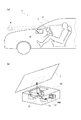
図1(a)には、本実施例のヘッドアップディスプレイ装置(以下、HUD装置)10が車両1に搭載された様子が示されている。図示されるように、本実施例のヘッドアップディスプレイ装置(以下、HUD装置)10は、運転席から見て車両1の前方のダッシュボード3内に搭載されており、ウィンドシールド2に向けて画像を投影する。すると、HUD装置10から投影された画像がウィンドシールド2で反射して運転者の目に到達し、その結果、運転者は、投影された画像の虚像を、ウィンドシールド2の向こう側に表示された表示画像4として認識する。尚、本実施例のウィンドシールド2は、本発明における「板状部材」に対応する。
Hereinafter, examples will be described in order to clarify the contents of the present invention described above.
FIG. 1A shows a state in which a head-up display device (hereinafter, HUD device) 10 of this embodiment is mounted on a vehicle 1. As shown in the figure, a head-up display device (hereinafter referred to as a HUD device) 10 according to the present embodiment is mounted in a
また、図1(b)に示されるように、本実施例のHUD装置10は、主に液晶表示装置などによって構成されて画像を表示する画像表示部12と、画像表示部12を背面側から照明する照明装置100と、画像表示部12に表示されて照明装置100によって投影された画像を反射する平面鏡14と、平面鏡14によって反射された画像を更に反射してウィンドシールド2に投影する凹面鏡16とを備えている。凹面鏡16によってウィンドシールド2には拡大された画像が投影され、その画像が運転者に認識される。
As shown in FIG. 1B, the
尚、本実施例の照明装置100は、本発明における「画像照明部」に対応する。また、本実施例の凹面鏡16は、本発明における「凹面鏡要素」に対応する。更に、本実施例の平面鏡14、凹面鏡16、およびウィンドシールド2は、本発明における「表示光学系」に対応する。
また、本実施例のHUD装置10では、画像表示部12が主に液晶表示装置によって構成されているものとして説明するが、マトリックス状に配列した微少な反射鏡の角度を制御することで画像を表示する反射型の画像表示部12を用いることもできる。この場合は、画像表示部12は前方から照明装置100によって照明される。
また、本実施例のHUD装置10では、凹面鏡16を用いることによって、ウィンドシールド2に投影される画像を拡大している。しかし、ウィンドシールド2の手前側(運転者側)にコンバイナーと呼ばれる透明な板状部材を設け、このコンバイナーを凹面形状とすることによって、運転者には画像が拡大されて見えるようにしても良い。
The
Further, in the
In the
図2には、本実施例のHUD装置10が、画像表示部12で表示された画像を拡大して虚像表示する原理が示されている。尚、実際のHUD装置10には平面鏡14が設けられているが、この平面鏡14は光路を折り曲げるためのものであり、画像の表示には直接の関係がないため、図2では省略されている。ウィンドシールド2についても、凹面鏡16から投影された光を運転者に向けて反射するだけで、画像が虚像として表示されることとは関係がないため、図2では省略されている。
尚、本実施例では、凹面鏡16は1つだけ用いられているが、凹面鏡16で反射した画像を更に別の凹面鏡を用いて反射するようにしてもよい。このような場合、図2に示した凹面鏡16は、それら複数の凹面鏡による多段の反射を代表したものとなる。
また、図2に示したように、画像表示部12に表示された画像を拡大して虚像表示するためのHUD装置10の光学系を、以下では「HUD光学系」と称する。
FIG. 2 shows the principle that the
In this embodiment, only one
In addition, as shown in FIG. 2, the optical system of the
HUD光学系では、凹面鏡16の焦点距離が、比較的長い値に設定されている。そして、画像表示部12は、凹面鏡16の焦点距離よりも凹面鏡16に近い位置に設けられる。図1(b)に示した例では、画像表示部12と凹面鏡16との間に平面鏡14が設けられているので、画像表示部12から平面鏡14までの距離と、平面鏡14から凹面鏡16までの距離との合計が、凹面鏡16の焦点距離よりも短くなっている。こうすれば、凹面鏡16で反射された画像表示部12の画像が、虚像として運転者に認識される。
また、このときの虚像が表示される位置や、画像表示部12の画像に対する虚像の拡大倍率は、凹面鏡16の焦点距離と、画像表示部12から凹面鏡16までの距離とに基づいて、所定の計算式で算出された位置および倍率となる。
In the HUD optical system, the focal length of the
The position at which the virtual image is displayed and the magnification of the virtual image with respect to the image on the
ここで、車両1の運転者の身長や運転席に着座したときの姿勢などは運転者によって違うので、それに応じて運転者の目の位置も変化する。そこで、HUD装置10では、代表的な運転者の目の位置を中心とする一定領域を想定して、この領域内に運転者の目がある限りは良好に虚像を視認できるように、HUD光学系が設定されている。尚、このように設定された一定領域は、アイボックス5と呼ばれる。
Here, since the height of the driver of the vehicle 1 and the posture when sitting on the driver's seat differ depending on the driver, the position of the driver's eyes changes accordingly. In view of this, the
当然ながら、運転者の目がアイボックス5内にある限りは、十分な輝度の虚像を表示する必要がある。そのためには、画像表示部12を背面から照らす光源の輝度を上げて、画像表示部12で表示される画像の輝度を高くすれば良いが、それでは光源の放熱量が増加するなどの種々の弊害を引き起こす。
そこで、光源からの光が効率よくアイボックス5に到達するようにすることで、光源の輝度を高めた場合と同様な効果が得られるようにすることが考えられる。そのためには、凹面鏡16が作るアイボックス5の入射瞳6に向かって、光源の光を効率よく供給してやればよい。ここで、アイボックス5の入射瞳6とは、凹面鏡16が、画像表示部12側に結像させるアイボックス5の実像である。アイボックス5の入射瞳6と、アイボックス5とは、凹面鏡16によって共役な関係にあるので、入射瞳6を通過する光は(凹面鏡16に向かう光である限り)必ずアイボックス5を通過する。従って、光源からの光を効率よく入射瞳6に導くことができれば、その光は必ずアイボックス5に到達するので光量を増やすことができ、光源の輝度を高めた場合と同様な効果を得ることができる。
Of course, as long as the driver's eyes are in the
Therefore, it is conceivable to obtain the same effect as when the luminance of the light source is increased by making the light from the light source efficiently reach the
このような着想に基づく光学系としては、実は、顕微鏡などで観察試料を照明するために用いられる光学系が存在する。顕微鏡ではレンズ類の口径が小さいので光量が不足しがちであるが、むやみに光源の輝度を高めると、観察試料が光源からの熱の影響を受けてしまう虞がある。そこで顕微鏡では、光源からの光を、接眼レンズの入射瞳に供給することによって、観察者が十分な明るさで試料を観察できるようにした特殊な光学系が、照明用の光学系として採用されている。
しかし、顕微鏡などでは、観察者の目の位置は接眼レンズの位置に固定されているのに対して、HUD装置10では、アイボックス5の範囲内で自由に移動し得る。また、アイボックス5の大きさは、水平方向には15〜20センチメートル程度、垂直方向には5〜10センチメートル程度の範囲に設定されることが一般的である。従って、顕微鏡の入射瞳(すなわち、顕微鏡の光学系によって得られる接眼レンズの実像)が点と見なせる大きさであるのに比べると、HUD装置10の入射瞳6はかなりの大きさとなる。このため、顕微鏡で用いられる照明用の光学系は、そのままではHUD装置10の照明に適用できないことが予想される。
As an optical system based on such an idea, there is actually an optical system used for illuminating an observation sample with a microscope or the like. In a microscope, the lens diameter is small, so the amount of light tends to be insufficient. However, if the luminance of the light source is increased unnecessarily, the observation sample may be affected by the heat from the light source. Therefore, in the microscope, a special optical system that allows the observer to observe the sample with sufficient brightness by supplying light from the light source to the entrance pupil of the eyepiece is adopted as the illumination optical system. ing.
However, in the microscope or the like, the position of the observer's eyes is fixed at the position of the eyepiece, whereas the
図3には、HUD装置10で画像表示部12を背面から照明するための光学系が概念的に示されている。尚、画像表示部12を背面から照射するための光学系を、画像表示部12の画像を虚像表示するための光学系(HUD光学系)と区別するために、以下では「照明光学系」と称するものとする。
FIG. 3 conceptually shows an optical system for illuminating the
前述したように、HUD装置10の入射瞳6は、凹面鏡16によって得られるアイボックス5の実像と考えて良いから、入射瞳6が形成される位置は、凹面鏡16の焦点距離と、凹面鏡16からアイボックス5までの距離とによって決まってしまう。そして、この位置は、図3に示したように、画像表示部12のかなり後方となる。また、入射瞳6の大きさについても、凹面鏡16の焦点距離と、凹面鏡16からアイボックス5までの距離と、アイボックス5の大きさとによって決まってしまう。
従って、HUD装置10の照明光学系は、HUD光学系によって画像表示部12の後方に形成される入射瞳6を、レンズLを用いて光源Eの光放出面に結像させるような光学系となる。
As described above, since the
Therefore, the illumination optical system of the
また、車両1に搭載する関係上、HUD装置10はコンパクトにする必要があるため、画像表示部12から光源Eまでの距離はあまり長くできない。従って、比較的短い距離で、アイボックス5の入射瞳6を、光源Eの大きさ(光源EがLEDであれば、直径で数ミリメートル程度の大きさ)に縮小できるように、焦点距離の短いレンズLが必要となる。加えて、画像表示部12の全面を照らす必要があるので、レンズLは十分な口径を有していることも必要となる。
実際の数値を用いて、レンズLの仕様を検討してみると、レンズを製造できないか、製造できてもレンズとしては十分に機能しない仕様となってしまう。すなわち、顕微鏡などで採用されている照明用の光学系を、そのままHUD装置10の照明光学系に適用しようとしても、そのような照明光学系は成立し得ない。そこで、本実施例のHUD装置10および照明装置100では、以下のような照明光学系を採用した。
In addition, since the
When the specification of the lens L is examined using actual numerical values, the lens cannot be manufactured, or even if manufactured, the specification does not function as a lens sufficiently. That is, even if the illumination optical system employed in a microscope or the like is applied to the illumination optical system of the
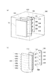
図4(a)には、本実施例のHUD装置10に搭載された照明装置100の内部構造が示されている。また、図4(b)には、照明装置100に組み込まれた照明光学系の分解組立図が示されている。
図示されるように、主に液晶画面によって構成される画像表示部12の背面側には、複数の小レンズ102Lが連なって構成されたレンズアレイ102が設けられている。
FIG. 4A shows the internal structure of the
As shown in the drawing, a
また、それぞれの小レンズ102Lの背面側には、円柱形状のライトパイプ104が1本ずつ設けられている。ライトパイプ104は、アクリル樹脂やガラスなどの透明材料で形成されており、外周側面には金属膜が蒸着されて内周面が反射鏡となっている。更に、円柱の両端面は光学的に研磨されている。
このため、一方の端面からライトパイプ104に入射した光は、内周側面で反射を繰り返しながらライトパイプ104の内部を進行して、他方の端面104bから出射する。そして、光が出射する側の端面104bはレンズアレイ102を向いているため、端面104bから出射した光は小レンズ102Lに入射する。
Further, one
For this reason, the light incident on the
更に、ライトパイプ104のもう一方の端面の側には、光源としてのLED106が設けられている。LED106は、ライトパイプ104の端面に近付けて設けられており、このため、LED106から放出されたほとんど全ての光が、端面からライトパイプ104の内部に入射される。そして、入射した光は、内周側面で反射を繰り返しながらライトパイプ104の中を進行する。
従って、LED106が放出する光に輝度や色の偏りが存在していた場合でも、ライトパイプ104の内周側面で反射を繰り返すことによって偏りが均一化され、小レンズ102Lに向いた側の端面104bからは、輝度や色の偏りが無い、均一化された光が出射される。
そして、本実施例の照明装置100では、ライトパイプ104が小レンズ102Lに向けて光を出射する側の端面104bが、次のような位置、すなわち、HUD光学系によって得られるアイボックス5の入射瞳6を、小レンズ102Lが結像させる位置に設けられている。
Further, an
Therefore, even when there is a luminance or color bias in the light emitted from the
And in the illuminating
この点について、図5を参照しながら詳しく説明する。図5(a)には、ライトパイプ104の中心軸の位置で取った照明装置100の断面が示されている。また、図5(b)には、参考として、HUD光学系によって得られるアイボックス5の入射瞳6が示されている。
This point will be described in detail with reference to FIG. FIG. 5A shows a cross section of the
図5(b)に示されるように、アイボックス5の入射瞳6は照明装置100の更に後方に形成されるが、本実施例では、図5(a)に示すように、複数の小レンズ102Lによって入射瞳6が分割されている。そして、それぞれの小レンズ102Lがアイボックス5の入射瞳6を結像させる位置に、ライトパイプ104の一方の端面104bが設けられている。このため、ライトパイプ104のもう一方の端面104aからLED106の光を入射してやれば、端面104bから出射される均一な光を、HUD光学系が入射瞳6を結像させる光路に供給することができる。
そして、全てのライトパイプ104について同様なことをすれば、端面104bから出射される均一な光によって、HUD光学系が入射瞳6を結像させる光路を満たしてやることができる。その結果、アイボックス5の全領域を、輝度や色の偏りを生じさせることなく均一に照明することが可能となり、アイボックス5内で運転者の目の位置が移動しても、画像の見え方(明るさや色)が変わらないようにすることができる。
尚、本実施例では、ライトパイプ104の光を出射する側の端面104bが、本発明における「光放出面」に対応する。
As shown in FIG. 5B, the
If the same thing is done for all the
In this embodiment, the
また、アイボックス5の入射瞳6と、アイボックス5とは、HUD光学系(図2に示した例では凹面鏡16)を介して共役な関係にあるから、原理的には、ライトパイプ104の端面104bから出射された全ての光がアイボックス5に到達する。このため、光を効率よく照明に利用することができるので、運転者の目がアイボックス5内にあれば、十分な明るさの画像を表示することができる。
In addition, since the
加えて、LED106の光放出面は、ライトパイプ104のもう一方の端面104aの直ぐ近くに設けられている。このため、LED106から放出されたほとんど全ての光がライトパイプ104に入射し、入射した光はライトパイプ104の内周面で反射されて、ほとんど損失することなく、端面104bから出射される。
結局、LED106から放出されたほとんど全ての光を照明に用いることができるので、照明効率が高くなり、光源の輝度を高くしなくても、十分な明るさで画像を表示することが可能となる。
また、LED106から放出されたほとんど全ての光がライトパイプ104を介してレンズアレイ102に供給されるので、画像の表示に関与しない光(いわゆる迷光)の発生が抑制される。このため、コントラストの高い、はっきりした虚像を表示することができ、また、虚像が二重に見えるなどの問題が生じることも回避することができる。
In addition, the light emission surface of the
Eventually, since almost all of the light emitted from the
In addition, since almost all of the light emitted from the
更に、レンズアレイ102を構成する個々の小レンズ102Lは口径が小さいので、焦点距離を短くすることができ、しかもレンズアレイ102全体としては十分な口径を実現することができる。このため、画像表示部12からLED106までの距離を短く抑えながら、画像表示部12の全体を照明可能な照明装置100を実現することが可能となる。
Furthermore, since each
尚、上述した実施例では、ライトパイプ104の端面104bから出射した光は、そのまま小レンズ102Lに供給されるものとして説明した。しかし、端面104bからの光を、拡散板を介して小レンズ102Lに供給しても良い。
In the embodiment described above, the light emitted from the
図6には、レンズアレイ102とライトパイプ104との間に、拡散板110が設けられた変形例の照明装置100が例示されている。拡散板110としては、いわゆる磨りガラスや、微粒子を分散させたアクリル板などを用いることができる。
尚、拡散板110を用いる場合、HUD光学系によって得られるアイボックス5の入射瞳6を小レンズ102Lが結像させる位置は、厳密には、拡散板110のレンズアレイ102側の表面であることが望ましい。しかし、実際には、ライトパイプ104の端面104bに結像させたままで、端面104bの手前側に拡散板110を追加しただけでも、実用上の問題は生じない。
また、本変形例では、ライトパイプ104とは別に、拡散板110を設けるものとして説明するが、ライトパイプ104の出射側の端面104bを、磨りガラス状に仕上げたり、シボ加工を施したり、更には、出射側の端面104bに磨りガラス状の薄いフィルムを貼り付けたりしてもよい。
尚、本変形例の拡散板110は、本発明における「拡散部」に対応する。
FIG. 6 illustrates a modified
When the
In addition, in this modification, a description will be given assuming that the
The
拡散板110は、ライトパイプ104の端面104bから出射した光を拡散させるので、ライトパイプ104が光を均一化する作用を補う効果を有する。このため、ライトパイプ104の端面104bに拡散板110を設けることで、ライトパイプ104の長さを短くすることが可能となり、照明装置100を小型化することが可能となる。
The diffusing
また、ライトパイプ104の端面104bからの光は、ライトパイプ104の中心軸の方向に指向性を持って出射されるが、拡散板110は指向性を弱める効果を有しており、拡散板110を通った光は、万遍なく、ある程度の広がりを持って放出される。このため、前述したように、それぞれの小レンズ102Lに対して、ライトパイプ104およびLED106を1つずつ設けるのではなく、1つのライトパイプ104およびLED106から複数の小レンズ102Lに光を供給することができる。その結果、照明装置100に搭載されるライトパイプ104およびLED106の数を減少させることができるので、故障の可能性が減少し、更に容易に製造することが可能となる。
Light from the
加えて、拡散板110を用いれば、以下の理由から、照明装置100をより一層小型化することが可能である。すなわち、図7(a)に例示するように、レンズアレイ102を形成する小レンズ102Lを小さくすれば、レンズアレイ102の焦点距離を更に短くすることができるので、ライトパイプ104をレンズアレイ102に近付けて配置することができる。
更に、図7(b)に例示するように、小レンズ102Lを複数列に配列すれば、レンズアレイ102の大きさも小さくすることができる。
もっとも、図7に例示するように、小レンズ102Lを小さくすると、レンズアレイ102に含まれる小レンズ102Lの数が多くなる。しかし、拡散板110を用いれば、1つのライトパイプ104およびLED106から複数の小レンズ102Lに光を供給することができる。このため、レンズアレイ102に含まれる小レンズ102Lの数が多くなっても、ライトパイプ104およびLED106の数が増加することを抑制することができる。
In addition, if the
Furthermore, as illustrated in FIG. 7B, if the
However, as illustrated in FIG. 7, when the
以上、本実施例について説明したが、本発明は上記の実施例に限られるものではなく、その要旨を逸脱しない範囲において種々の態様で実施することができる。 As mentioned above, although the present Example was described, this invention is not limited to said Example, In the range which does not deviate from the summary, it can implement in a various aspect.
例えば、上述した実施例では、凹面鏡16を用いてウィンドシールド2に画像を投影することによって、運転者に虚像を表示するものとして説明した。しかし、図8に例示したように、ウィンドシールド2の手前側に、透明な材料によって凹面形状に形成されたコンバイナー24を設け、このコンバイナー24に投影装置22から画像を投影することによって、HUD装置20を形成しても良い。
For example, in the above-described embodiment, it has been described that a virtual image is displayed to the driver by projecting an image onto the
1…車両、 2…ウィンドシールド、 3…ダッシュボード、
4…表示画像、 5…アイボックス、 6…入射瞳、
10…HUD装置、 12…画像表示部、 14…平面鏡、
16…凹面鏡、 10…HUD装置、 22…投影装置、
24…コンバイナー、 100…照明装置、 102…レンズアレイ、
102L…小レンズ、 104…ライトパイプ、 106…LED、
110…拡散板。
1 ... vehicle, 2 ... windshield, 3 ... dashboard,
4 ... Display image, 5 ... Eye box, 6 ... Entrance pupil,
10 ... HUD device, 12 ... Image display unit, 14 ... Plane mirror,
16 ... concave mirror, 10 ... HUD device, 22 ... projection device,
24 ... Combiner, 100 ... Lighting device, 102 ... Lens array,
102L ... small lens, 104 ... light pipe, 106 ... LED,
110: Diffuser.
Claims (7)
前記虚像表示しようとする画像を表示する画像表示部と、
前記画像表示部に表示された前記画像を照明する画像照明部と、
少なくとも1つの凹面鏡要素を有することによって、前記照明された前記画像を前記運転者に対して虚像表示する表示光学系と
を備え、
前記画像照明部は、
前記照明のための光を放出する光放出面と、
前記画像表示部と前記光放出面との間に配置されるとともに、前記運転者の目が存在し得る範囲として想定されたアイボックスの前記表示光学系による入射瞳を、前記光放出面上に分割して結像させるレンズアレイと
を備えるヘッドアップディスプレイ装置。 A head-up display device that displays a virtual image on the scenery in front of the driver,
An image display unit for displaying an image to be displayed as the virtual image;
An image illumination unit that illuminates the image displayed on the image display unit;
A display optical system for displaying a virtual image of the illuminated image to the driver by having at least one concave mirror element;
The image illumination unit includes:
A light emitting surface for emitting light for the illumination;
Is disposed between the light emitting surface and the image display unit Rutotomoni, the entrance pupil by the display optical system of the supposed eye box as a range eyes may exist of the driver, on the light emitting surface A head-up display device comprising: a lens array for dividing and forming an image .
前記表示光学系は、
前記運転者の前方に設けられた透明な板状部材と、
前記板状部材に向けて前記画像を投影する凹面鏡と
を備えた光学系であるヘッドアップディスプレイ装置。 The head-up display device according to claim 1,
The display optical system includes:
A transparent plate-like member provided in front of the driver;
A concave mirror for projecting the image toward the plate-shaped member;
A head-up display device which is an optical system including
前記画像表示部は、光の透過率を変更することによって前記画像を表示する透過型の表示部であり、
前記画像照明部は、前記画像表示部の背面側から前記画像を照明する照明部であるヘッドアップディスプレイ装置。 The head-up display device according to claim 1 or 2,
The image display unit is a transmissive display unit that displays the image by changing light transmittance,
The image illumination unit is a head-up display device that is an illumination unit that illuminates the image from the back side of the image display unit.
前記画像照明部は、一端側から入射された光源の光を内周側面で反射することによって他端側から出射するライトパイプを備え、
前記光放出面は、前記ライトパイプの出射側の端面であるヘッドアップディスプレイ装置。 A head-up display device according to 請 Motomeko 3,
The image illumination unit includes a light pipe that emits from the other end side by reflecting light of the light source incident from one end side on the inner peripheral side surface,
The head-up display device , wherein the light emission surface is an end surface of the light pipe on an emission side .
前記ライトパイプの前記出射側の端面には、該端面から出射した光を拡散させる拡散部が設けられているヘッドアップディスプレイ装置。 The head-up display device according to claim 4,
A head-up display device in which a diffusion portion for diffusing light emitted from the end surface is provided on an end surface on the emission side of the light pipe .
前記ライトパイプは、前記レンズアレイが前記入射瞳を分割して結像させる位置ごとに設けられているヘッドアップディスプレイ装置。 The head-up display device according to claim 4 or 5,
The light pipe is a head-up display device provided at each position where the lens array forms an image by dividing the entrance pupil .
前記ライトパイプは、前記出射側の端面からの光を、前記レンズアレイに含まれる複数の小レンズに向かって出射するライトパイプであるヘッドアップディスプレイ装置。 The head-up display device according to claim 5 ,
The light pipe is a head-up display device that is a light pipe that emits light from an end face on the emission side toward a plurality of small lenses included in the lens array .
Priority Applications (6)
| Application Number | Priority Date | Filing Date | Title |
|---|---|---|---|
| JP2013130061A JP5974987B2 (en) | 2013-06-20 | 2013-06-20 | Head-up display device and lighting device used for head-up display device |
| CN201480035130.7A CN105359030A (en) | 2013-06-20 | 2014-06-19 | Head-up display device, and illuminating device employed in head-up display device |
| PCT/JP2014/003285 WO2014203534A1 (en) | 2013-06-20 | 2014-06-19 | Head-up display device, and illuminating device employed in head-up display device |
| DE112014002900.9T DE112014002900T5 (en) | 2013-06-20 | 2014-06-19 | Head-up display device and lighting device for a head-up display device |
| KR1020157035616A KR101766573B1 (en) | 2013-06-20 | 2014-06-19 | Head-up display device, and illuminating device employed in head-up display device |
| US14/899,492 US9835858B2 (en) | 2013-06-20 | 2014-06-19 | Head-up display device and illuminating device for head-up display device |
Applications Claiming Priority (1)
| Application Number | Priority Date | Filing Date | Title |
|---|---|---|---|
| JP2013130061A JP5974987B2 (en) | 2013-06-20 | 2013-06-20 | Head-up display device and lighting device used for head-up display device |
Publications (3)
| Publication Number | Publication Date |
|---|---|
| JP2015004825A JP2015004825A (en) | 2015-01-08 |
| JP2015004825A5 JP2015004825A5 (en) | 2015-08-13 |
| JP5974987B2 true JP5974987B2 (en) | 2016-08-23 |
Family
ID=52104285
Family Applications (1)
| Application Number | Title | Priority Date | Filing Date |
|---|---|---|---|
| JP2013130061A Active JP5974987B2 (en) | 2013-06-20 | 2013-06-20 | Head-up display device and lighting device used for head-up display device |
Country Status (6)
| Country | Link |
|---|---|
| US (1) | US9835858B2 (en) |
| JP (1) | JP5974987B2 (en) |
| KR (1) | KR101766573B1 (en) |
| CN (1) | CN105359030A (en) |
| DE (1) | DE112014002900T5 (en) |
| WO (1) | WO2014203534A1 (en) |
Families Citing this family (38)
| Publication number | Priority date | Publication date | Assignee | Title |
|---|---|---|---|---|
| JP6369148B2 (en) | 2014-06-09 | 2018-08-08 | 株式会社デンソー | Head-up display device and lighting unit thereof |
| JP6287605B2 (en) | 2014-06-09 | 2018-03-07 | 株式会社デンソー | Head-up display device and lighting unit thereof |
| KR102424949B1 (en) * | 2015-04-24 | 2022-07-25 | 엘지이노텍 주식회사 | Head-up display device |
| KR102362729B1 (en) * | 2015-04-24 | 2022-02-15 | 엘지이노텍 주식회사 | Head up display apparatus |
| CN104866106A (en) * | 2015-06-03 | 2015-08-26 | 深圳市光晕网络科技有限公司 | HUD and infrared identification-combined man-machine interactive method and system |
| CN104875680B (en) * | 2015-06-03 | 2018-03-16 | 深圳市光晕网络科技有限公司 | A kind of HUD display devices of combination voice and video identification |
| JP6354667B2 (en) | 2015-06-05 | 2018-07-11 | 株式会社デンソー | Head-up display device |
| EP3349051B1 (en) * | 2015-09-07 | 2020-05-20 | Luoyang Institute of Electro-Optical Equipment of AVIC | Collimation display apparatus, and vehicle-mounted or airborne head-up display apparatus |
| CN108351518B (en) | 2015-10-27 | 2021-07-23 | 麦克赛尔株式会社 | Information display device |
| JP6459921B2 (en) | 2015-11-19 | 2019-01-30 | 株式会社デンソー | Head-up display device |
| EP3693784B1 (en) * | 2016-01-19 | 2022-03-16 | Nippon Seiki Co., Ltd. | Head-up display device and lens unit |
| JP6319354B2 (en) * | 2016-02-23 | 2018-05-09 | 株式会社デンソー | Head-up display device |
| JP6319355B2 (en) * | 2016-02-23 | 2018-05-09 | 株式会社デンソー | Head-up display device |
| KR20180116350A (en) | 2016-02-26 | 2018-10-24 | 매직 립, 인코포레이티드 | A display system having a plurality of light pipes for a plurality of light emitters |
| JP6579126B2 (en) | 2016-05-25 | 2019-09-25 | 株式会社デンソー | Head-up display device and image projection unit |
| DE102016109951A1 (en) * | 2016-05-31 | 2017-11-30 | Valeo Schalter Und Sensoren Gmbh | Light generating device for a head-up display of a motor vehicle |
| CN107843985A (en) * | 2017-11-27 | 2018-03-27 | 上海驾馥电子科技有限公司 | Augmented reality HUD system and method |
| EP3726276B1 (en) | 2017-12-11 | 2023-03-22 | Panasonic Intellectual Property Management Co., Ltd. | Head-up display and moving body with head-up display mounted thereon |
| EP3726277A4 (en) | 2017-12-11 | 2020-12-30 | Panasonic Intellectual Property Management Co., Ltd. | Head-up display and moving body with head-up display mounted thereon |
| CN109991737B (en) * | 2017-12-29 | 2024-06-14 | 深圳点石创新科技有限公司 | Optical projection system |
| JP6593464B2 (en) * | 2018-01-12 | 2019-10-23 | 株式会社Jvcケンウッド | Virtual image display device |
| JP6593494B1 (en) * | 2018-06-08 | 2019-10-23 | 株式会社Jvcケンウッド | Virtual image display device |
| JP6593465B2 (en) * | 2018-01-12 | 2019-10-23 | 株式会社Jvcケンウッド | Virtual image display device |
| KR102077635B1 (en) * | 2018-01-12 | 2020-02-14 | 가부시키가이샤 제이브이씨 켄우드 | Virtual display |
| JP6593463B2 (en) * | 2018-01-12 | 2019-10-23 | 株式会社Jvcケンウッド | Virtual image display device |
| JP6593461B2 (en) * | 2018-01-12 | 2019-10-23 | 株式会社Jvcケンウッド | Virtual image display device |
| CN110275295B (en) * | 2018-03-14 | 2022-09-16 | 蒋晶 | Diffractive display system |
| CN108501722B (en) | 2018-03-30 | 2020-06-02 | 京东方科技集团股份有限公司 | Vehicle-mounted display system |
| JP6793882B2 (en) * | 2018-05-24 | 2020-12-02 | 三菱電機株式会社 | Display control device for vehicles |
| CN110543016A (en) * | 2018-05-31 | 2019-12-06 | 深圳疆程技术有限公司 | Head-up display based on laser light source |
| JP6734340B2 (en) * | 2018-10-01 | 2020-08-05 | 本田技研工業株式会社 | Display device, display control method, and program |
| JP7250582B2 (en) * | 2019-03-26 | 2023-04-03 | 京セラ株式会社 | Image display module, moving body, and optical system |
| JP7059986B2 (en) * | 2019-07-18 | 2022-04-26 | 株式会社デンソー | Windshield display device |
| DE102019130751A1 (en) * | 2019-11-14 | 2021-05-20 | Carl Zeiss Microscopy Gmbh | Lighting module for variable-angle lighting |
| KR20210064684A (en) * | 2019-11-26 | 2021-06-03 | 삼성전자주식회사 | Light shielding film for hud and hud system for vehicle |
| JP7277785B2 (en) * | 2020-04-10 | 2023-05-19 | 日亜化学工業株式会社 | light emitting device |
| KR102578802B1 (en) * | 2021-04-07 | 2023-09-15 | 한국과학기술원 | Lens array optical sheet and optical device including the same |
| US11994769B1 (en) * | 2023-07-20 | 2024-05-28 | E-Lead Electronic Co., Ltd. | Backlit display device with tapered reflective cup array |
Family Cites Families (18)
| Publication number | Priority date | Publication date | Assignee | Title |
|---|---|---|---|---|
| US6534152B2 (en) * | 1989-09-28 | 2003-03-18 | Ppg Industries Ohio, Inc. | Windshield for head-up display system |
| JP2002031845A (en) * | 2000-07-19 | 2002-01-31 | Seiko Epson Corp | Projector |
| US7128431B2 (en) | 2001-10-10 | 2006-10-31 | Siemens Aktiengesellschaft | Display device |
| JP3991764B2 (en) * | 2002-05-10 | 2007-10-17 | セイコーエプソン株式会社 | Illumination device and projection display device |
| JP2004126025A (en) * | 2002-09-30 | 2004-04-22 | Nippon Seiki Co Ltd | Display device |
| US7616638B2 (en) | 2003-07-29 | 2009-11-10 | Orbital Data Corporation | Wavefront detection and disambiguation of acknowledgments |
| JP2005070255A (en) * | 2003-08-22 | 2005-03-17 | Denso Corp | Virtual image display device |
| JP2005141202A (en) * | 2003-11-03 | 2005-06-02 | Arisawa Mfg Co Ltd | Transmission type screen |
| JP2006019027A (en) * | 2004-06-30 | 2006-01-19 | Nippon Seiki Co Ltd | Lighting system |
| JP2007058163A (en) * | 2005-07-27 | 2007-03-08 | Ricoh Co Ltd | Light source apparatus, optical modulation apparatus, display apparatus, light condensing lighting system and projection type color display apparatus |
| CN201177183Y (en) * | 2006-04-10 | 2009-01-07 | 马仁勇 | Optical diode light gathering device |
| JP4539760B2 (en) | 2007-08-29 | 2010-09-08 | エプソンイメージングデバイス株式会社 | Electronics |
| US7764254B2 (en) | 2007-08-29 | 2010-07-27 | Epson Imaging Devices Corporation | Electro-optical device and electronic apparatus |
| JP5126051B2 (en) | 2008-12-25 | 2013-01-23 | 株式会社デンソー | Lighting device |
| KR101780420B1 (en) * | 2011-03-24 | 2017-09-22 | 삼성디스플레이 주식회사 | Back-light unit and 3-dimensional image display device having the same |
| JP5674032B2 (en) * | 2011-03-25 | 2015-02-18 | 日本精機株式会社 | Head-up display device |
| JP5941292B2 (en) | 2012-02-10 | 2016-06-29 | 矢崎総業株式会社 | Vehicle display device |
| JP5920095B2 (en) * | 2012-07-31 | 2016-05-18 | 株式会社Jvcケンウッド | Image display device |
-
2013
- 2013-06-20 JP JP2013130061A patent/JP5974987B2/en active Active
-
2014
- 2014-06-19 CN CN201480035130.7A patent/CN105359030A/en active Pending
- 2014-06-19 DE DE112014002900.9T patent/DE112014002900T5/en not_active Ceased
- 2014-06-19 US US14/899,492 patent/US9835858B2/en active Active
- 2014-06-19 KR KR1020157035616A patent/KR101766573B1/en active IP Right Grant
- 2014-06-19 WO PCT/JP2014/003285 patent/WO2014203534A1/en active Application Filing
Also Published As
| Publication number | Publication date |
|---|---|
| DE112014002900T5 (en) | 2016-03-10 |
| CN105359030A (en) | 2016-02-24 |
| US9835858B2 (en) | 2017-12-05 |
| US20160147061A1 (en) | 2016-05-26 |
| KR101766573B1 (en) | 2017-08-08 |
| WO2014203534A1 (en) | 2014-12-24 |
| JP2015004825A (en) | 2015-01-08 |
| KR20160010558A (en) | 2016-01-27 |
Similar Documents
| Publication | Publication Date | Title |
|---|---|---|
| JP5974987B2 (en) | Head-up display device and lighting device used for head-up display device | |
| WO2019157987A1 (en) | Monocular large field-of-view near-eye display device and binocular large field-of-view near-eye display device | |
| US7599012B2 (en) | Luminous display device | |
| CN106716228B (en) | Head-up display | |
| EP3447561B1 (en) | Head-up display device | |
| JP2015004825A5 (en) | ||
| US20170115553A1 (en) | Scanning projector transmissive screen, and scanning projector system | |
| WO2014119407A1 (en) | Head-up display device | |
| WO2016060119A1 (en) | Head-up display device | |
| JP6921327B2 (en) | HUD lighting system, head-up display device and implementation method | |
| TW201243455A (en) | Planar light source device and liquid crystal display device | |
| KR20040049146A (en) | Head mounted display | |
| JP6579180B2 (en) | Virtual image display device | |
| CN109239835A (en) | Waveguide, imaging expanded mode group, light source module group, near-eye display system and equipment | |
| JP4797531B2 (en) | Video display device | |
| JP4827614B2 (en) | Light source device and image display device having the same | |
| JP2016180922A (en) | Head-up display device | |
| JP2004045496A (en) | Two-dimensional optical scanner and video display device | |
| US10527923B2 (en) | Scanning projector transmissive screen, and scanning projector system | |
| CN111123511A (en) | Illumination system and illumination method | |
| US11662655B2 (en) | Rod lens array, and lighting optical system and device including same | |
| JP2009063914A (en) | Display device | |
| JP6923016B2 (en) | Optics and projectors | |
| JP2017227681A (en) | Head-up display device | |
| JP6658797B2 (en) | Optical element for head-up display |
Legal Events
| Date | Code | Title | Description |
|---|---|---|---|
| A521 | Request for written amendment filed |
Free format text: JAPANESE INTERMEDIATE CODE: A523 Effective date: 20150625 |
|
| A621 | Written request for application examination |
Free format text: JAPANESE INTERMEDIATE CODE: A621 Effective date: 20150722 |
|
| TRDD | Decision of grant or rejection written | ||
| A01 | Written decision to grant a patent or to grant a registration (utility model) |
Free format text: JAPANESE INTERMEDIATE CODE: A01 Effective date: 20160621 |
|
| A61 | First payment of annual fees (during grant procedure) |
Free format text: JAPANESE INTERMEDIATE CODE: A61 Effective date: 20160704 |
|
| R151 | Written notification of patent or utility model registration |
Ref document number: 5974987 Country of ref document: JP Free format text: JAPANESE INTERMEDIATE CODE: R151 |
|
| R250 | Receipt of annual fees |
Free format text: JAPANESE INTERMEDIATE CODE: R250 |
|
| R250 | Receipt of annual fees |
Free format text: JAPANESE INTERMEDIATE CODE: R250 |
|
| R250 | Receipt of annual fees |
Free format text: JAPANESE INTERMEDIATE CODE: R250 |
|
| R250 | Receipt of annual fees |
Free format text: JAPANESE INTERMEDIATE CODE: R250 |
|
| R250 | Receipt of annual fees |
Free format text: JAPANESE INTERMEDIATE CODE: R250 |
|
| R250 | Receipt of annual fees |
Free format text: JAPANESE INTERMEDIATE CODE: R250 |