JP7059986B2 - Windshield display device - Google Patents
Windshield display device Download PDFInfo
- Publication number
- JP7059986B2 JP7059986B2 JP2019133113A JP2019133113A JP7059986B2 JP 7059986 B2 JP7059986 B2 JP 7059986B2 JP 2019133113 A JP2019133113 A JP 2019133113A JP 2019133113 A JP2019133113 A JP 2019133113A JP 7059986 B2 JP7059986 B2 JP 7059986B2
- Authority
- JP
- Japan
- Prior art keywords
- windshield
- occupant
- projector
- vehicle
- transparent screen
- Prior art date
- Legal status (The legal status is an assumption and is not a legal conclusion. Google has not performed a legal analysis and makes no representation as to the accuracy of the status listed.)
- Active
Links
- 239000012788 optical film Substances 0.000 claims description 7
- 230000000694 effects Effects 0.000 description 3
- 230000003287 optical effect Effects 0.000 description 3
- 229920002037 poly(vinyl butyral) polymer Polymers 0.000 description 3
- 238000005286 illumination Methods 0.000 description 2
- 229920005989 resin Polymers 0.000 description 2
- 239000011347 resin Substances 0.000 description 2
- 239000000853 adhesive Substances 0.000 description 1
- 230000001070 adhesive effect Effects 0.000 description 1
- 238000003491 array Methods 0.000 description 1
- 230000005540 biological transmission Effects 0.000 description 1
- 239000010408 film Substances 0.000 description 1
- 239000011521 glass Substances 0.000 description 1
- 230000001678 irradiating effect Effects 0.000 description 1
- 239000004973 liquid crystal related substance Substances 0.000 description 1
- 238000012986 modification Methods 0.000 description 1
- 230000004048 modification Effects 0.000 description 1
- 239000000758 substrate Substances 0.000 description 1
Images


Classifications
-
- B—PERFORMING OPERATIONS; TRANSPORTING
- B60—VEHICLES IN GENERAL
- B60K—ARRANGEMENT OR MOUNTING OF PROPULSION UNITS OR OF TRANSMISSIONS IN VEHICLES; ARRANGEMENT OR MOUNTING OF PLURAL DIVERSE PRIME-MOVERS IN VEHICLES; AUXILIARY DRIVES FOR VEHICLES; INSTRUMENTATION OR DASHBOARDS FOR VEHICLES; ARRANGEMENTS IN CONNECTION WITH COOLING, AIR INTAKE, GAS EXHAUST OR FUEL SUPPLY OF PROPULSION UNITS IN VEHICLES
- B60K35/00—Arrangement of adaptations of instruments
-
- B60K35/23—
-
- B60K35/50—
-
- B60K35/60—
-
- B60K35/654—
-
- B60K35/656—
-
- G—PHYSICS
- G02—OPTICS
- G02B—OPTICAL ELEMENTS, SYSTEMS OR APPARATUS
- G02B27/00—Optical systems or apparatus not provided for by any of the groups G02B1/00 - G02B26/00, G02B30/00
- G02B27/0081—Optical systems or apparatus not provided for by any of the groups G02B1/00 - G02B26/00, G02B30/00 with means for altering, e.g. enlarging, the entrance or exit pupil
-
- G—PHYSICS
- G02—OPTICS
- G02B—OPTICAL ELEMENTS, SYSTEMS OR APPARATUS
- G02B27/00—Optical systems or apparatus not provided for by any of the groups G02B1/00 - G02B26/00, G02B30/00
- G02B27/01—Head-up displays
- G02B27/0101—Head-up displays characterised by optical features
-
- G—PHYSICS
- G03—PHOTOGRAPHY; CINEMATOGRAPHY; ANALOGOUS TECHNIQUES USING WAVES OTHER THAN OPTICAL WAVES; ELECTROGRAPHY; HOLOGRAPHY
- G03B—APPARATUS OR ARRANGEMENTS FOR TAKING PHOTOGRAPHS OR FOR PROJECTING OR VIEWING THEM; APPARATUS OR ARRANGEMENTS EMPLOYING ANALOGOUS TECHNIQUES USING WAVES OTHER THAN OPTICAL WAVES; ACCESSORIES THEREFOR
- G03B21/00—Projectors or projection-type viewers; Accessories therefor
- G03B21/54—Accessories
- G03B21/56—Projection screens
-
- B60K2360/334—
-
- B60K2360/785—
-
- G—PHYSICS
- G02—OPTICS
- G02B—OPTICAL ELEMENTS, SYSTEMS OR APPARATUS
- G02B27/00—Optical systems or apparatus not provided for by any of the groups G02B1/00 - G02B26/00, G02B30/00
- G02B27/01—Head-up displays
- G02B27/0101—Head-up displays characterised by optical features
- G02B2027/0123—Head-up displays characterised by optical features comprising devices increasing the field of view
Description
本発明は、ウィンドシールド表示装置に関する。 The present invention relates to a windshield display device.
従来、自動車等の移動体に備えられた透明な板状部材に映像光を投写することで、乗員に対して、透明な板状部材の前方の景色に重ねて画像を視認させるヘッドアップディスプレイ装置として、例えば特許文献1に記載のものが提案されている。なお、以下、ヘッドアップディスプレイ装置を「HUD装置」と称する。
Conventionally, a head-up display device that projects an image light onto a transparent plate-shaped member provided on a moving body such as an automobile so that an occupant can visually recognize an image superimposed on the scenery in front of the transparent plate-shaped member. For example, the one described in
特許文献1に記載のHUD装置は、画像表示部と、画像表示部を背面側から照明する照明部と、画像表示部を介して照明部から投影された光を反射する平面鏡と、平面鏡からの光を反射してウィンドシールドに投影する凹面鏡とを備える。このHUD装置は、画像表示部に表示された画像を凹面鏡により拡大してウィンドシールドに投写し、拡大された当該画像をウィンドシールドよりも前方の空間に虚像として表示させ、当該虚像を運転者等に認識させる構成とされている。
The HUD device described in
このHUD装置は、ダッシュボード内に搭載され、ダッシュボードからウィンドシールドに向かって光を照射する。HUD装置から照射された光は、ウィンドシールドで反射した後、運転者のアイボックスに到達する。 This HUD device is mounted in the dashboard and emits light from the dashboard toward the windshield. The light emitted from the HUD device reaches the driver's eyebox after being reflected by the windshield.
近年、上記したHUD装置のように、ウィンドシールドを介して運転者に各種画像を認識させる表示装置の分野において、画像の表示領域を大きくしたいとのニーズが存在する。 In recent years, there is a need to increase the display area of an image in the field of a display device that allows a driver to recognize various images via a windshield, such as the above-mentioned HUD device.
しかしながら、上記のHUD装置では、ユーザに視認させる画像の表示領域は、ウィンドシールドのうちユーザの正面に位置する一部の領域に限られる。仮に、このHUD装置によりウィンドシールドのうち従来よりも広い所定以上の領域において画像の表示を行う場合、映像光を投写する領域を広くするために、光源および凹面鏡を大きくしなければならず、HUD装置自体が大型化してしまう。 However, in the above-mentioned HUD device, the display area of the image visually recognized by the user is limited to a part of the windshield located in front of the user. If an image is displayed in a predetermined area larger than the conventional one in the windshield by this HUD device, the light source and the concave mirror must be enlarged in order to widen the area for projecting the image light, and the HUD must be enlarged. The device itself becomes large.
本発明は、上記の点に鑑み、ウィンドシールドを介して運転者等に映像を視認させるものであって、光源の大型化を抑制しつつも、ウィンドシールドのうち所定以上の領域にて映像を視認させることが可能なウィンドシールド表示装置を提供することを目的とする。 In view of the above points, the present invention allows the driver or the like to visually recognize the image through the windshield, and while suppressing the increase in size of the light source, the image is displayed in a predetermined area or more of the windshield. It is an object of the present invention to provide a windshield display device that can be visually recognized.
上記目的を達成するため、請求項1に記載のウィンドシールド表示装置は、車両(V)のウィンドシールド(V1)を介して乗員に映像を視認させるウィンドシールド表示装置であって、ウィンドシールドに重ねて配置される透明スクリーン(3)と、透明スクリーンに映像光を投写するプロジェクター(1、2)と、を備え、プロジェクターは、車両の車室内のうち車両の車幅方向におけるウィンドシールドの端部に隣接する端部隣接部に配置されると共に、ウィンドシールドの車幅方向における所定以上の領域に映像光を投写し、透明スクリーンは、車両の外部からの外光を車室内に透過させると共に、映像光を、車両の運転席に着座する第1乗員(C1)のアイボックス(4)もしくは助手席に着座する第2乗員(C2)のアイボックス(5)またはその両方に反射する構成とされており、プロジェクターは、第1乗員に映像を視認させるために用いられる第1プロジェクター(1)であり、車幅方向のうち運転席から助手席に向かう方向を第1方向として、第1プロジェクターは、ウィンドシールドの第1方向における端部に隣接する端部隣接部に配置されており、透明スクリーンは、プロジェクターからの映像光を第1乗員のアイボックスに反射する第1反射部(3a)と、第1反射部とは異なる部分であって、映像光を第2乗員のアイボックスに反射する第2反射部(3b)とを有してなる1枚の光学フィルムである。
In order to achieve the above object, the windshield display device according to
これにより、ウィンドシールドに重畳配置された透明スクリーンに、車幅方向におけるウィンドシールドの端部に隣接する端部隣接部に搭載されたプロジェクターから映像光を投写する構成のウィンドシールド表示装置となる。このような構成において、透明スクリーンは、運転席もしくは助手席またはその両方にて映像光を反射し、運転席に着座する乗員もしくは助手席に着座する乗員またはその両方に映像を視認させる構成とされている。 As a result, the windshield display device is configured to project the image light from the projector mounted on the transparent screen superimposed on the windshield and adjacent to the end portion adjacent to the end portion of the windshield in the vehicle width direction. In such a configuration, the transparent screen is configured to reflect the image light in the driver's seat and / or the passenger's seat so that the image can be visually recognized by the occupant seated in the driver's seat and / or the occupant seated in the passenger seat. ing.
プロジェクターを車両の端部隣接部に配置することにより、ウィンドシールドに重畳配置された透明スクリーンの所定以上の領域に映像光を投写でき、光源の大型化を抑制できる。また、映像光を反射して乗員に映像を視認させる透明スクリーン構成とすることで、乗員がウィンドシールドの位置において従来のHUD装置よりも広範囲の領域で映像を視認可能となる。 By arranging the projector adjacent to the end of the vehicle, it is possible to project the image light on a predetermined area or more of the transparent screen superimposed on the windshield, and it is possible to suppress the increase in size of the light source. Further, by adopting a transparent screen configuration that reflects the image light to allow the occupant to visually recognize the image, the occupant can visually recognize the image in a wider area than the conventional HUD device at the position of the windshield.
よって、光源の大型化を抑制しつつも、ウィンドシールドのうち従来のHUD装置よりも広範囲の所定以上の領域にて映像を乗員に視認させることが可能なウィンドシールド表示装置となる。 Therefore, the windshield display device is capable of allowing the occupant to visually recognize the image in a predetermined area or more in a wider range than the conventional HUD device among the windshields while suppressing the increase in size of the light source.
なお、各構成要素等に付された括弧付きの参照符号は、その構成要素等と後述する実施形態に記載の具体的な構成要素等との対応関係の一例を示すものである。 The reference numerals in parentheses attached to each component or the like indicate an example of the correspondence between the component or the like and the specific component or the like described in the embodiment described later.
以下、本発明の実施形態について図に基づいて説明する。なお、以下の各実施形態相互において、互いに同一もしくは均等である部分には、同一符号を付して説明を行う。 Hereinafter, embodiments of the present invention will be described with reference to the drawings. In each of the following embodiments, the parts that are the same or equal to each other will be described with the same reference numerals.
(第1実施形態)
第1実施形態のウィンドシールド表示装置S1について、図1~図4を参照して説明する。
(First Embodiment)
The windshield display device S1 of the first embodiment will be described with reference to FIGS. 1 to 4.
図1では、後述のプロジェクター1、2の搭載箇所を見易くするため、車両Vのステアリング等を省略している。図2では、見易くして理解を助けるため、後述の第1プロジェクター1からの映像光およびその反射光を実線で示し、後述の第2プロジェクター2からの映像光およびその反射光を一点鎖線で示すと共に、それらの向きに矢印を付している。
In FIG. 1, the steering of the vehicle V and the like are omitted in order to make it easier to see the mounting locations of the
以下、説明の便宜上、図1に矢印で示す紙面の左右方向を車両Vにおける「車幅方向」と称する。 Hereinafter, for convenience of explanation, the left-right direction of the paper surface indicated by the arrow in FIG. 1 is referred to as a "vehicle width direction" in the vehicle V.
本実施形態のウィンドシールド表示装置S1は、例えば図1に示すように、自動車等の車両Vに搭載され、プロジェクター1、2からウィンドシールドV1に向けて光を投写し、ウィンドシールドV1を介して運転者等に各種映像を視認させる構成とされている。
As shown in FIG. 1, for example, the windshield display device S1 of the present embodiment is mounted on a vehicle V such as an automobile, projects light from
なお、「ウィンドシールドV1を介して映像を視認させる」とは、第1プロジェクター1もしくは第2プロジェクター2またはその両方から透明スクリーン3に映像光を投写し、当該映像光を反射させることでユーザに各種映像を視認させることを意味する。
Note that "visualizing an image through the windshield V1" means that the image light is projected onto the
プロジェクター1、2は、透明スクリーン3に映像光を投写することで、ユーザに対してウィンドシールドV1の位置に各種映像を実像として視認させるために用いられる任意の光源である。プロジェクター1、2は、例えば、液晶方式、DLP(登録商標)方式、レーザ光走査式などの任意のプロジェクターとされる。DLPとは、デジタルライティングプロセッシングの略である。プロジェクター1、2は、例えば、図示しない他の車載装置に接続され、他の車載装置の表示画面などの各種映像に対応する映像信号に基づき、当該映像信号に対応する映像光を投写する。他の車載装置としては、例えば、ナビゲーション装置、車載カメラやカーエアコンなどの他の各種電子装置とされ得るが、これに限定されない。なお、この種のプロジェクターについては、公知のため、本明細書では詳細な説明を省略する。
The
プロジェクター1、2は、ウィンドシールドV1の所定以上の領域に映像光を投写できる位置に配置される。具体的には、プロジェクター1、2は、車両Vのうち車幅方向におけるウィンドシールドV1の端部に隣接する一部の領域である、端部隣接部V2に配置される。
The
なお、「ウィンドシールドV1の所定以上の領域」とは、従来のHUD装置にて虚像表示がなされる領域、すなわち、ウィンドシールドV1のうち運転席の正面に位置する所定の領域よりも広い領域を意味する。例えば、図2に示すように、ウィンドシールドV1のうち車両Vの運転席の正面に位置する所定の領域から当該車両Vの助手席の正面に位置する所定の領域に至るまでの広範な領域が「ウィンドシールドV1の所定以上の領域」に相当する。 The "region above a predetermined value of the windshield V1" is a region where a virtual image is displayed by the conventional HUD device, that is, a region of the windshield V1 wider than a predetermined region located in front of the driver's seat. means. For example, as shown in FIG. 2, a wide range of the windshield V1 from a predetermined area located in front of the driver's seat of the vehicle V to a predetermined area located in front of the passenger seat of the vehicle V is covered. Corresponds to "a region above a predetermined value of the windshield V1".
また、端部隣接部V2としては、例えば図1に示すように、ダッシュボードのうち車幅方向の端部を含む一部の領域などが挙げられる。本実施形態では、端部隣接部V2がダッシュボードの車両方向における端部の領域である例を代表例として説明する。 Further, as the end adjacent portion V2, for example, as shown in FIG. 1, a part of the dashboard including the end in the vehicle width direction and the like can be mentioned. In the present embodiment, an example in which the end adjacent portion V2 is the region of the end portion of the dashboard in the vehicle direction will be described as a representative example.
以下、説明の簡略化のため、車両Vの運転席に着座する乗員C1を「第1乗員C1」と称し、車両Vの助手席に着座する乗員C2を「第2乗員C2」と称する。また、第1乗員C1のアイボックス4を「第1アイボックス4」と称し、第2乗員C2のアイボックス5を「第2アイボックス5」と称する。さらに、説明の便宜上、車両Vの車幅方向のうち運転席側から助手席側に向かう方向を「第1方向」と称し、その反対方向を「第2方向」と称することがある。
Hereinafter, for the sake of simplification of the description, the occupant C1 seated in the driver's seat of the vehicle V will be referred to as a "first occupant C1", and the occupant C2 seated in the passenger seat of the vehicle V will be referred to as a "second occupant C2". Further, the
第1プロジェクター1は、図1に示すように、車両Vの端部隣接部V2のうち助手席側、すなわちダッシュボードの第1方向側の端部における所定の領域に搭載されている。第1プロジェクター1から透明スクリーン3に投写される映像光は、車両Vの運転席に着座する第1乗員C1の眼の位置として想定される長方形の領域である、第1アイボックス4内に反射され、運転席において各種映像として視認される。言い換えると、第1プロジェクター1は、透明スクリーン3に対して斜め前方から映像光を投写し、第1乗員C1に映像を視認させる第1乗員C1への映像表示用のプロジェクターである。
As shown in FIG. 1, the
第2プロジェクター2は、車両Vの端部隣接部V2のうち運転席側、すなわちダッシュボードの第2方向側の端部における所定の領域に搭載されている。第2プロジェクター2から透明スクリーン3に投写される映像光は、車両Vの助手席に着座する第2乗員C2の眼の位置として想定される長方形の領域である、第2アイボックス5内に反射され、運転席において各種映像として視認される。つまり、第2プロジェクター2は、透明スクリーン3に対して斜め前方から映像光を投写し、第2乗員C1に映像を視認させる第2乗員C2への映像表示用のプロジェクターである。
The
透明スクリーン3は、例えばPVB(ポリビニルブチラール)樹脂等の任意の透明接着剤を介して、ウィンドシールドV1の一部または全部の領域に重ねて配置されている。透明スクリーン3は、例えば図2に示すように、第1プロジェクター1から投写される映像光を第1アイボックス4に反射し、第2プロジェクター2から投写される映像光を第2アイボックス5に反射する構成とされている。
The
具体的には、透明スクリーン3は、特定の角度範囲で入射した光だけをその入射角に対応する特定の反射角で反射させ、それ以外の角度で入射した光を単に透過もしくは反射させることが可能な構成とされた光学部材とされる。例えば、図3に示すように、第1プロジェクター1から透明スクリーン3に入射する映像光の角度を入射角θ1とし、第1乗員C1に向けて反射する角度を反射角θ2とする。具体的には、入射角θ1は、透明スクリーン3のなす面のうち入射光が照射される点における当該面に対する法線と当該入射光とのなす角度である。反射角θ2は、透明スクリーン3のなす面のうち入射角θ1で入射した入射光が照射される点における当該面に対する法線と当該入射光を反射した反射光とのなす角度である。
Specifically, the
このとき、透明スクリーン3は、例えば図4に示すように、入射角θ1が30°、40°、50°、60°のとき、反射角θ2が順に20°、35°、55°、75°といった具合に入射した光を入射角θ1に応じた反射角θ2で反射する構成とされる。この入射角θ1と反射角θ2との関係は、プロジェクター1、2の映像光の投写口、透明スクリーン3およびアイボックス4、5の配置関係やウィンドシールドV1の曲率等により適宜変更される。
At this time, as shown in FIG. 4, for example, when the incident angles θ1 are 30 °, 40 °, 50 °, and 60 °, the reflection angles θ2 of the
なお、図4における入射角θ1については、図3に示すように、便宜上、入射光が法線よりも紙面左側にある場合を正とし、反射角θ2については、反射光が法線よりも紙面右側にある場合を正としたときの値である。そのため、透明スクリーン3の一部の領域では、反射角θ2が負の値になり得る。具体的には、例えば図3の例では、第1プロジェクター1からの映像光が、透明スクリーン3のうち第1アイボックス4の正面に位置する部分よりも紙面右側の領域で入射した場合において、その反射光を第1アイボックス4に入射させるときである。このとき、反射光を法線よりも紙面左側に反射させる必要があり、上記の定義によれば、反射角θ2は負の値となる。また、図3、図4では、第1プロジェクター1の映像光を第1アイボックス4に向けて反射させる場合を例に説明したが、第2プロジェクター2からの映像光を第2アイボックス5に向けて反射させる場合も、透明スクリーン3は、同様の思想で設計される。
As for the incident angle θ1 in FIG. 4, as shown in FIG. 3, for convenience, the case where the incident light is on the left side of the paper surface from the normal is positive, and for the reflected angle θ2, the reflected light is on the paper surface from the normal. This is the value when the case on the right side is positive. Therefore, the reflection angle θ2 can be a negative value in a part of the
透明スクリーン3は、例えば、図示しない凸状の楕円半球形状とされた複数のマイクロレンズが車室側に向かって凸となさるように繰り返し配列されてなるマイクロレンズアレイを有する光学フィルムである。透明スクリーン3は、図3に示すように、車室側から所定の角度で入射した光を反射する一方で、車室の外部からの外光を車室内に透過する。
The
透明スクリーン3は、図2に示すように、第1プロジェクター1からの映像光を第1アイボックス4に反射すると共に、第2プロジェクター2からの映像光を第2アイボックス5に反射する。言い換えると、透明スクリーン3は、本実施形態では、プロジェクター1、2の共通の実像表示用のスクリーンとして機能する。
As shown in FIG. 2, the
なお、この場合において、ウィンドシールドV1が車幅方向において対称な形状であるとき、各マイクロレンズは、例えば、左右対称な形状とされると共に、その対称な方向が車幅方向に沿うように配置される。また、このとき、当該マイクロレンズにより構成されるマイクロレンズアレイは、例えば、その対称軸が、ウィンドシールドV1の面方向であって、車幅方向に直交する方向におけるウィンドシールドV1の対称軸と重なるように配置される。これにより、透明スクリーン3は、車幅方向において、図4に示すような入射角θ1と反射角θ2との光学特性がいわば対称となる分布となり、図2に示すように異なる位置から投写される映像光をそれぞれ異なるアイボックス4、5に反射可能な構成となる。
In this case, when the windshield V1 has a symmetrical shape in the vehicle width direction, each microlens has, for example, a symmetrical shape and is arranged so that the symmetrical direction is along the vehicle width direction. Will be done. Further, at this time, the microlens array composed of the microlenses, for example, has its symmetry axis overlapping with the symmetry axis of the windshield V1 in the plane direction of the windshield V1 and orthogonal to the vehicle width direction. Arranged like this. As a result, the
これにより、ウィンドシールドV1よりも前方からの外光を透過させつつ、所定角度から入射した映像光を第1アイボックス4または第2アイボックス5に反射させる透明スクリーン3となり、外界の視野の確保と映像表示とを両立できる。透明スクリーン3としては、例えば、住友化学株式会社製のLumisty(登録商標)フィルムなどが使用され得る。
As a result, it becomes a
以上が、本実施形態のウィンドシールド表示装置S1の基本的な構成である。このような構成とされることで、以下の効果が得られる。 The above is the basic configuration of the windshield display device S1 of the present embodiment. With such a configuration, the following effects can be obtained.
プロジェクター1、2を車両Vのうち透明スクリーン3の車幅方向における端部に隣接する端部隣接部V2に配置することで、従来のHUD装置よりも広範な領域に映像光を投写することができ、プロジェクター1、2の大型化を抑制できる。また、透明スクリーン3により広範な領域に投写された映像光を第1アイボックス4または第2アイボックス5に反射させることで、乗員C1、C2がウィンドシールドV1において従来よりも広範囲で映像を視認できる。
By arranging the
また、特定角度の範囲で入射する光の反射角度が調整された透明スクリーン3を用いることにより、所定角度から入射する光に対する反射率が、通常用いられる透明な光拡散板を用いた場合における反射率よりも高くなる。これにより、プロジェクター1、2の光源の出力を通常の透明な光拡散板を用いる場合に比べて低くしつつも、映像の輝度を通常の透明な光拡散板を用いる場合と同等以上とできる。そのため、映像の輝度を確保しつつも、プロジェクター1、2の熱負荷を低減する効果が得られるウィンドシールド表示装置S1となる。
Further, by using the
本実施形態によれば、映像光を投写するための光源の大型化を抑制しつつも、ウィンドシールドV1の所定以上の領域において第1乗員C1および第2乗員C2に映像を視認させることが可能なウィンドシールド表示装置S1となる。 According to the present embodiment, it is possible to make the first occupant C1 and the second occupant C2 visually recognize the image in a predetermined area or more of the windshield V1 while suppressing the increase in size of the light source for projecting the image light. Windshield display device S1.
(第2実施形態)
第2実施形態のウィンドシールド表示装置S2について、図5を参照して説明する。図5では、図2と同様に、第1プロジェクター1からの映像光およびその反射光を実線で示すと共に、それらの向きに矢印を付している。
(Second Embodiment)
The windshield display device S2 of the second embodiment will be described with reference to FIG. In FIG. 5, as in FIG. 2, the image light from the
本実施形態のウィンドシールド表示装置S2は、実像表示のためのプロジェクターとして第1プロジェクター1のみを有し、第1プロジェクター1からの映像光を第1乗員C1の第1アイボックス4に反射させる構成とされている点で上記第1実施形態と相違する。つまり、ウィンドシールド表示装置S2は、第1乗員C1にのみウィンドシールドV1の位置に各種映像を視認させる構成とされている。
The windshield display device S2 of the present embodiment has only the
本実施形態によっても、映像光を投写するための光源の大型化を抑制しつつも、ウィンドシールドV1の所定以上の領域において第1乗員C1に映像を視認させることが可能なウィンドシールド表示装置S2となる。 Also in this embodiment, the windshield display device S2 capable of allowing the first occupant C1 to visually recognize the image in a predetermined area or more of the windshield V1 while suppressing the increase in size of the light source for projecting the image light. Will be.
(第3実施形態)
第3実施形態のウィンドシールド表示装置S3について、図6を参照して説明する。図6では、図2と同様に、第2プロジェクター2からの映像光およびその反射光を一点鎖線で示すと共に、それらの向きに矢印を付している。
(Third Embodiment)
The windshield display device S3 of the third embodiment will be described with reference to FIG. In FIG. 6, as in FIG. 2, the image light from the
本実施形態のウィンドシールド表示装置S3は、実像表示のためのプロジェクターとして第2プロジェクター2のみを有し、第2プロジェクター2からの映像光を第2乗員C2の第2アイボックス5に反射させる構成とされている点で上記第1実施形態と相違する。つまり、ウィンドシールド表示装置S3は、第2乗員C2にのみウィンドシールドV1の位置に各種映像を視認させる構成とされている。
The windshield display device S3 of the present embodiment has only the
本実施形態によっても、映像光を投写するための光源の大型化を抑制しつつも、ウィンドシールドV1の所定以上の領域において第2乗員C2に映像を視認させることが可能なウィンドシールド表示装置S3となる。 Also in this embodiment, the windshield display device S3 capable of allowing the second occupant C2 to visually recognize the image in a predetermined area or more of the windshield V1 while suppressing the increase in size of the light source for projecting the image light. Will be.
(第4実施形態)
第4実施形態のウィンドシールド表示装置S4について、図7、図8を参照して説明する。図7では、図2と同様に、第2プロジェクター2からの映像光およびその反射光のうち第2アイボックス5に向かうものを一点鎖線で示し、当該映像光の反射光のうち第1アイボックス4に向かうものを実線で示すと共に、それらの向きに矢印を付している。
(Fourth Embodiment)
The windshield display device S4 of the fourth embodiment will be described with reference to FIGS. 7 and 8. In FIG. 7, similarly to FIG. 2, the image light from the
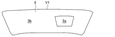
本実施形態のウィンドシールド表示装置S4は、実像表示のためのプロジェクターとして第2プロジェクター2のみを有する。このような構成において、透明スクリーン3は、例えば図7に示すように、第2プロジェクター2からの映像光を第1アイボックス4に反射する第1反射部3aと、当該映像光を第2アイボックス5に反射する第2反射部3bとを有してなる。ウィンドシールド表示装置S4は、これらの点において上記第1実施形態と相違する。本実施形態では、この相違点について主に説明する。
The windshield display device S4 of the present embodiment has only the
透明スクリーン3は、例えば図8に示すように、ウィンドシールドV1の全域に重ねて配置されると共に、一部が第1乗員C1への映像提示のための第1反射部3aとされている。また、透明スクリーン3は、第1反射部3aとは異なる部分が、第2乗員C2への映像提示のための第2反射部3bとされている。つまり、透明スクリーン3は、第1反射部3aと第2反射部3bとを有する1枚の光学フィルムとされ、本実施形態では、第2プロジェクター2の映像光により第1乗員C1および第2乗員C2のいずれも映像を視認できる構成とされている。
As shown in FIG. 8, for example, the
第1反射部3aは、例えば図8に示すように、第2反射部3bに囲まれると共に、第2反射部3bよりもその面積が小さくされている。第1反射部3aおよび第2反射部3bは、その配置や面積等については適宜変更されてもよい。
As shown in FIG. 8, for example, the first reflecting
本実施形態によれば、映像光を投写するための光源の大型化を抑制でき、ウィンドシールドV1の所定以上の領域において第2乗員C2に映像を視認させつつも、第1乗員C1にも映像を視認させることが可能なウィンドシールド表示装置S4となる。また、本実施形態では、1つのプロジェクターにより、第1乗員C1および第2乗員C2に異なる映像を視認させることも可能になる。 According to the present embodiment, it is possible to suppress the increase in size of the light source for projecting the image light, and while the second occupant C2 is made to visually recognize the image in the region equal to or larger than the predetermined area of the windshield V1, the first occupant C1 is also able to see the image. This is a windshield display device S4 capable of visually recognizing. Further, in the present embodiment, it is possible to make the first occupant C1 and the second occupant C2 visually recognize different images by one projector.
なお、上記の例では、第2プロジェクター2のみを有する構成とされた場合について説明したが、第1プロジェクター1のみを有する構成であっても同様の効果が得られる。この場合、第1反射部3aは、例えば図9に示すように、第2反射部3bよりも面積が大きくされ、第2反射部3bを囲む配置とされ得る。
In the above example, the case where only the
(他の実施形態)
本発明は、実施例に準拠して記述されたが、本発明は当該実施例や構造に限定されるものではないと理解される。本発明は、様々な変形例や均等範囲内の変形をも包含する。加えて、様々な組み合わせや形態、さらには、それらの一要素のみ、それ以上、あるいはそれ以下、を含む他の組み合わせや形態をも、本発明の範疇や思想範囲に入るものである。
(Other embodiments)
Although the present invention has been described in accordance with the examples, it is understood that the present invention is not limited to the examples and structures. The present invention also includes various modifications and variations within a uniform range. In addition, various combinations and forms, as well as other combinations and forms including only one element thereof, more or less, are also within the scope and scope of the present invention.
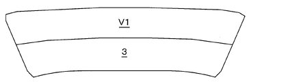
(1)上記各実施形態では、透明スクリーン3がウィンドシールドV1の全域に配置された場合について説明したが、これに限定されない。例えば図10に示すように、透明スクリーン3は、ウィンドシールドV1のうち下半分の領域にのみ配置されてもよい。これにより、ウィンドシールドV1の位置に映像を表示する所定以上の領域を確保しつつも、ウィンドシールドV1のうち透明スクリーン3が配置されない領域には映像が表示されず、より外界の視野を確保できる構成のウィンドシールド表示装置となる。
(1) In each of the above embodiments, the case where the
なお、透明スクリーン3は、ウィンドシールドV1のうち車幅方向における両端を繋ぐ方向に沿って配置されることが好ましく、ウィンドシールドV1の上半分にのみ配置されてもよいし、ウィンドシールドV1の下側の所定の範囲内にのみ配置されてもよい。このように、透明スクリーン3は、ウィンドシールドV1の一部の任意の領域に配置され得る。
The
(2)上記第1実施形態において、プロジェクター1、2から共通の透明スクリーン3に映像光を投写する例について説明した。しかしながら、透明スクリーン3は、例えば図11に示すように、第1スクリーン31と、第2スクリーン32との2枚の光学フィルムにより構成されてもよい。第1スクリーン31は、例えば第1プロジェクター1からの映像光を第1アイボックス4に反射する。第2スクリーン32は、例えば第2プロジェクター2からの映像光を第2アイボックス5に反射する。このように、透明スクリーン3は、第1プロジェクター1に対応する部分と第2プロジェクター2に対応する部分とにより構成され得る。
(2) In the first embodiment, an example of projecting image light from the
これにより、第1スクリーン31と第2スクリーン32とで、マイクロレンズアレイの形状や配置関係を異なるものとでき、光の入射角θ1と反射角θ2との関係、すなわち透明スクリーン3の光学特性の自由度を向上させ得る。なお、上記のスクリーン31、32の配置については、逆であってもよい。
As a result, the shape and arrangement of the microlens arrays can be different between the
(3)上記各実施形態では、端部隣接部V2がダッシュボードの一部である例について説明したが、端部隣接部V2は、プロジェクター1、2がウィンドシールドV1に対して所定以上の領域に映像光を投写可能な箇所であればよく、ダッシュボードに限定されない。端部隣接部V2は、例えば、車両VのうちウィンドシールドV1の車幅方向における端部に隣接するピラー、いわゆるAピラーであってもよい。この場合、プロジェクター1、2は、ウィンドシールドV1の全域に映像光を投写することができる。
(3) In each of the above embodiments, an example in which the end adjacent portion V2 is a part of the dashboard has been described, but in the end adjacent portion V2, the
(4)上記各実施形態では、透明スクリーン3は、ウィンドシールドV1の外表面のうち車両Vの車室側の外表面に配置された例について説明したが、映像光をアイボックス4、5の一方または両方に反射できる配置であればよく、この配置に限定されない。例えば、透明スクリーン3は、ウィンドシールドV1を構成する2枚のガラス基材の間にPVB樹脂などを介して配置されてもよい。つまり、本明細書における「透明スクリーン3がウィンドシールドV1に重ねて配置される」とは、透明スクリーン3がウィンドシールドV1の外表面に配置されるだけでなく、内部に配置されることも含む。
(4) In each of the above embodiments, the example in which the
1、2 プロジェクター
3 透明スクリーン
4、5 アイボックス
V 車両
V1 ウィンドシールド
C1、C2 乗員
1, 2
Claims (9)
前記ウィンドシールドに重ねて配置される透明スクリーン(3)と、
前記透明スクリーンに映像光を投写するプロジェクター(1、2)と、を備え、
前記プロジェクターは、前記車両の車室内のうち前記車両の車幅方向における前記ウィンドシールドの端部に隣接する端部隣接部に配置されると共に、前記ウィンドシールドの前記車幅方向における所定以上の領域に前記映像光を投写し、
前記透明スクリーンは、前記車両の外部からの外光を車室内に透過させると共に、前記映像光を、前記車両の運転席に着座する第1乗員(C1)のアイボックス(4)もしくは助手席に着座する第2乗員(C2)のアイボックス(5)または前記第1乗員および前記第2乗員の両方のアイボックスに反射する構成とされており、
前記プロジェクターは、前記第1乗員に前記映像を視認させるために用いられる第1プロジェクター(1)であり、
前記車幅方向のうち前記運転席から前記助手席に向かう方向を第1方向として、
前記第1プロジェクターは、前記ウィンドシールドの前記第1方向における端部に隣接する前記端部隣接部に配置されており、
前記透明スクリーンは、前記プロジェクターからの前記映像光を前記第1乗員のアイボックスに反射する第1反射部(3a)と、前記第1反射部とは異なる部分であって、前記映像光を前記第2乗員のアイボックスに反射する第2反射部(3b)とを有してなる1枚の光学フィルムである、ウィンドシールド表示装置。 It is a windshield display device that allows the occupant to visually recognize the image through the windshield (V1) of the vehicle (V).
A transparent screen (3) placed on top of the windshield,
A projector (1, 2) that projects image light on the transparent screen is provided.
The projector is arranged in an end adjacent portion of the vehicle interior of the vehicle adjacent to the end of the windshield in the vehicle width direction of the vehicle, and is a region of the windshield above a predetermined value in the vehicle width direction. Project the above-mentioned image light on the
The transparent screen transmits external light from the outside of the vehicle into the vehicle interior, and transmits the image light to the eye box (4) or the passenger seat of the first occupant (C1) seated in the driver's seat of the vehicle. It is configured to reflect on the eyebox (5) of the second occupant (C2) to be seated or the eyeboxes of both the first occupant and the second occupant .
The projector is a first projector (1) used to make the first occupant visually recognize the image.
Of the vehicle width directions, the direction from the driver's seat to the passenger seat is set as the first direction.
The first projector is arranged at the end adjacent portion adjacent to the end of the windshield in the first direction.
The transparent screen is a portion different from the first reflecting portion (3a) that reflects the video light from the projector to the eye box of the first occupant, and the video light is said to be the same. A windshield display device , which is a single optical film having a second reflecting portion (3b) that reflects on the eye box of a second occupant .
前記ウィンドシールドに重ねて配置される透明スクリーン(3)と、A transparent screen (3) placed on top of the windshield,
前記透明スクリーンに映像光を投写するプロジェクター(1、2)と、を備え、A projector (1, 2) that projects image light on the transparent screen is provided.
前記プロジェクターは、前記車両の車室内のうち前記車両の車幅方向における前記ウィンドシールドの端部に隣接する端部隣接部に配置されると共に、前記ウィンドシールドの前記車幅方向における所定以上の領域に前記映像光を投写し、The projector is arranged in an end adjacent portion of the vehicle interior of the vehicle adjacent to the end of the windshield in the vehicle width direction of the vehicle, and is a region of the windshield above a predetermined value in the vehicle width direction. Project the above-mentioned image light on the
前記透明スクリーンは、前記車両の外部からの外光を車室内に透過させると共に、前記映像光を、前記車両の運転席に着座する第1乗員(C1)のアイボックス(4)もしくは助手席に着座する第2乗員(C2)のアイボックス(5)または前記第1乗員および前記第2乗員の両方のアイボックスに反射する構成とされており、The transparent screen transmits external light from the outside of the vehicle into the vehicle interior, and transmits the image light to the eye box (4) or the passenger seat of the first occupant (C1) seated in the driver's seat of the vehicle. It is configured to reflect on the eyebox (5) of the second occupant (C2) to be seated or the eyeboxes of both the first occupant and the second occupant.
前記プロジェクターは、前記第2乗員に前記映像を視認させるために用いられる第2プロジェクター(2)であり、The projector is a second projector (2) used to make the second occupant visually recognize the image.
前記車幅方向のうち前記運転席から前記助手席に向かう方向を第1方向とし、前記第1方向の反対方向を第2方向として、Of the vehicle width directions, the direction from the driver's seat to the passenger seat is defined as the first direction, and the direction opposite to the first direction is defined as the second direction.
前記第2プロジェクターは、前記ウィンドシールドの前記第2方向における端部に隣接する前記端部隣接部に配置されている、ウィンドシールド表示装置。The second projector is a windshield display device arranged at the end adjacent portion adjacent to the end portion of the windshield in the second direction.
前記ウィンドシールドに重ねて配置される透明スクリーン(3)と、A transparent screen (3) placed on top of the windshield,
前記透明スクリーンに映像光を投写するプロジェクター(1、2)と、を備え、A projector (1, 2) that projects image light on the transparent screen is provided.
前記プロジェクターは、前記車両の車室内のうち前記車両の車幅方向における前記ウィンドシールドの端部に隣接する端部隣接部に配置されると共に、前記ウィンドシールドの前記車幅方向における所定以上の領域に前記映像光を投写し、The projector is arranged in an end adjacent portion of the vehicle interior of the vehicle adjacent to the end of the windshield in the vehicle width direction of the vehicle, and is a region of the windshield above a predetermined value in the vehicle width direction. Project the above-mentioned image light on the
前記透明スクリーンは、前記車両の外部からの外光を車室内に透過させると共に、前記映像光を、前記車両の運転席に着座する第1乗員(C1)のアイボックス(4)もしくは助手席に着座する第2乗員(C2)のアイボックス(5)または前記第1乗員および前記第2乗員の両方のアイボックスに反射する構成とされており、The transparent screen transmits external light from the outside of the vehicle into the vehicle interior, and transmits the image light to the eye box (4) or the passenger seat of the first occupant (C1) seated in the driver's seat of the vehicle. It is configured to reflect on the eyebox (5) of the second occupant (C2) to be seated or the eyeboxes of both the first occupant and the second occupant.
前記プロジェクターは、前記映像光を前記第1乗員に視認させるために用いられる第1プロジェクター(1)と、前記映像光を前記第2乗員に視認させるために用いられる第2プロジェクター(2)とを有してなり、The projector includes a first projector (1) used to make the video light visible to the first occupant, and a second projector (2) used to make the video light visible to the second occupant. Have
前記車幅方向のうち前記運転席から前記助手席に向かう方向を第1方向とし、前記第1方向の反対方向を第2方向として、Of the vehicle width directions, the direction from the driver's seat to the passenger seat is defined as the first direction, and the direction opposite to the first direction is defined as the second direction.
前記第1プロジェクターは、前記ウィンドシールドの前記第1方向における端部に隣接する前記端部隣接部に配置されており、The first projector is arranged at the end adjacent portion adjacent to the end of the windshield in the first direction.
前記第2プロジェクターは、前記ウィンドシールドの前記第2方向における端部に隣接する前記端部隣接部に配置されている、ウィンドシールド表示装置。The second projector is a windshield display device arranged at the end adjacent portion adjacent to the end portion of the windshield in the second direction.
前記第1スクリーンは、前記第2スクリーンとは異なる位置に配置されている、請求項4に記載のウィンドシールド表示装置。 The transparent screen has a first screen (31) that reflects the image light of the first projector to the eye box of the first occupant, and a second screen that reflects the image light of the second projector to the eye box of the second occupant. It is composed of two optical films with two screens (32).
The windshield display device according to claim 4, wherein the first screen is arranged at a position different from that of the second screen.
Priority Applications (3)
| Application Number | Priority Date | Filing Date | Title |
|---|---|---|---|
| JP2019133113A JP7059986B2 (en) | 2019-07-18 | 2019-07-18 | Windshield display device |
| PCT/JP2020/026554 WO2021010227A1 (en) | 2019-07-18 | 2020-07-07 | Windshield display device |
| US17/559,420 US20220113539A1 (en) | 2019-07-18 | 2021-12-22 | Windshield display device |
Applications Claiming Priority (1)
| Application Number | Priority Date | Filing Date | Title |
|---|---|---|---|
| JP2019133113A JP7059986B2 (en) | 2019-07-18 | 2019-07-18 | Windshield display device |
Publications (3)
| Publication Number | Publication Date |
|---|---|
| JP2021018295A JP2021018295A (en) | 2021-02-15 |
| JP2021018295A5 JP2021018295A5 (en) | 2021-07-26 |
| JP7059986B2 true JP7059986B2 (en) | 2022-04-26 |
Family
ID=74210708
Family Applications (1)
| Application Number | Title | Priority Date | Filing Date |
|---|---|---|---|
| JP2019133113A Active JP7059986B2 (en) | 2019-07-18 | 2019-07-18 | Windshield display device |
Country Status (3)
| Country | Link |
|---|---|
| US (1) | US20220113539A1 (en) |
| JP (1) | JP7059986B2 (en) |
| WO (1) | WO2021010227A1 (en) |
Families Citing this family (1)
| Publication number | Priority date | Publication date | Assignee | Title |
|---|---|---|---|---|
| JP2022063933A (en) * | 2020-10-13 | 2022-04-25 | 株式会社Subaru | Display device for vehicle |
Citations (3)
| Publication number | Priority date | Publication date | Assignee | Title |
|---|---|---|---|---|
| WO2014203534A1 (en) | 2013-06-20 | 2014-12-24 | 株式会社デンソー | Head-up display device, and illuminating device employed in head-up display device |
| JP2016101805A (en) | 2014-11-27 | 2016-06-02 | パイオニア株式会社 | Display device, control method, program and storage medium |
| US20180172993A1 (en) | 2016-12-20 | 2018-06-21 | Panasonic Automotive Systems Company Of America, Division Of Panasonic Corporation Of North America | Side view safety display in a motor vehicle |
Family Cites Families (3)
| Publication number | Priority date | Publication date | Assignee | Title |
|---|---|---|---|---|
| EP0946893B1 (en) * | 1996-12-20 | 2002-04-17 | Siemens Aktiengesellschaft | Information display system for at least one person |
| CN107921871B (en) * | 2015-08-26 | 2020-05-19 | 富士胶片株式会社 | Projection display device, projection display method, and non-transitory computer-readable storage medium storing projection display program |
| JP7117066B2 (en) * | 2019-02-15 | 2022-08-12 | マクセル株式会社 | Vehicle information display device and vehicle information display system |
-
2019
- 2019-07-18 JP JP2019133113A patent/JP7059986B2/en active Active
-
2020
- 2020-07-07 WO PCT/JP2020/026554 patent/WO2021010227A1/en active Application Filing
-
2021
- 2021-12-22 US US17/559,420 patent/US20220113539A1/en not_active Abandoned
Patent Citations (3)
| Publication number | Priority date | Publication date | Assignee | Title |
|---|---|---|---|---|
| WO2014203534A1 (en) | 2013-06-20 | 2014-12-24 | 株式会社デンソー | Head-up display device, and illuminating device employed in head-up display device |
| JP2016101805A (en) | 2014-11-27 | 2016-06-02 | パイオニア株式会社 | Display device, control method, program and storage medium |
| US20180172993A1 (en) | 2016-12-20 | 2018-06-21 | Panasonic Automotive Systems Company Of America, Division Of Panasonic Corporation Of North America | Side view safety display in a motor vehicle |
Also Published As
| Publication number | Publication date |
|---|---|
| JP2021018295A (en) | 2021-02-15 |
| WO2021010227A1 (en) | 2021-01-21 |
| US20220113539A1 (en) | 2022-04-14 |
Similar Documents
| Publication | Publication Date | Title |
|---|---|---|
| JP5930231B2 (en) | Projection device and head-up display device | |
| US7298557B2 (en) | Projection unit for a head-up display | |
| WO2018154956A1 (en) | Head-up display device | |
| JP6601431B2 (en) | Head-up display device | |
| JP7397925B2 (en) | Vehicle information display device and vehicle information display system | |
| WO2020183844A1 (en) | Head-up display device | |
| US11353713B2 (en) | Virtual image display device | |
| US11092804B2 (en) | Virtual image display device | |
| US11131851B2 (en) | Virtual image display device | |
| JP6414131B2 (en) | Projection device and head-up display device | |
| JP7059986B2 (en) | Windshield display device | |
| US11300796B2 (en) | Virtual image display device | |
| US11119317B2 (en) | Virtual image display device | |
| JP2021109594A (en) | Information display device for vehicle | |
| JP6593494B1 (en) | Virtual image display device | |
| JP6593463B2 (en) | Virtual image display device | |
| JP2018095157A (en) | On-vehicle display device | |
| WO2020059618A1 (en) | Head-up display device |
Legal Events
| Date | Code | Title | Description |
|---|---|---|---|
| A521 | Request for written amendment filed |
Free format text: JAPANESE INTERMEDIATE CODE: A523 Effective date: 20210528 |
|
| A621 | Written request for application examination |
Free format text: JAPANESE INTERMEDIATE CODE: A621 Effective date: 20210528 |
|
| TRDD | Decision of grant or rejection written | ||
| A01 | Written decision to grant a patent or to grant a registration (utility model) |
Free format text: JAPANESE INTERMEDIATE CODE: A01 Effective date: 20220315 |
|
| A61 | First payment of annual fees (during grant procedure) |
Free format text: JAPANESE INTERMEDIATE CODE: A61 Effective date: 20220328 |
|
| R151 | Written notification of patent or utility model registration |
Ref document number: 7059986 Country of ref document: JP Free format text: JAPANESE INTERMEDIATE CODE: R151 |