JP5973138B2 - Backlight unit - Google Patents
Backlight unit Download PDFInfo
- Publication number
- JP5973138B2 JP5973138B2 JP2011151730A JP2011151730A JP5973138B2 JP 5973138 B2 JP5973138 B2 JP 5973138B2 JP 2011151730 A JP2011151730 A JP 2011151730A JP 2011151730 A JP2011151730 A JP 2011151730A JP 5973138 B2 JP5973138 B2 JP 5973138B2
- Authority
- JP
- Japan
- Prior art keywords
- heat radiating
- heat
- disposed
- backlight unit
- radiating portion
- Prior art date
- Legal status (The legal status is an assumption and is not a legal conclusion. Google has not performed a legal analysis and makes no representation as to the accuracy of the status listed.)
- Expired - Fee Related
Links
Images


Classifications
-
- G—PHYSICS
- G02—OPTICS
- G02F—OPTICAL DEVICES OR ARRANGEMENTS FOR THE CONTROL OF LIGHT BY MODIFICATION OF THE OPTICAL PROPERTIES OF THE MEDIA OF THE ELEMENTS INVOLVED THEREIN; NON-LINEAR OPTICS; FREQUENCY-CHANGING OF LIGHT; OPTICAL LOGIC ELEMENTS; OPTICAL ANALOGUE/DIGITAL CONVERTERS
- G02F1/00—Devices or arrangements for the control of the intensity, colour, phase, polarisation or direction of light arriving from an independent light source, e.g. switching, gating or modulating; Non-linear optics
- G02F1/01—Devices or arrangements for the control of the intensity, colour, phase, polarisation or direction of light arriving from an independent light source, e.g. switching, gating or modulating; Non-linear optics for the control of the intensity, phase, polarisation or colour
- G02F1/13—Devices or arrangements for the control of the intensity, colour, phase, polarisation or direction of light arriving from an independent light source, e.g. switching, gating or modulating; Non-linear optics for the control of the intensity, phase, polarisation or colour based on liquid crystals, e.g. single liquid crystal display cells
- G02F1/133—Constructional arrangements; Operation of liquid crystal cells; Circuit arrangements
- G02F1/1333—Constructional arrangements; Manufacturing methods
- G02F1/1335—Structural association of cells with optical devices, e.g. polarisers or reflectors
- G02F1/1336—Illuminating devices
- G02F1/133602—Direct backlight
- G02F1/133608—Direct backlight including particular frames or supporting means
-
- G—PHYSICS
- G02—OPTICS
- G02B—OPTICAL ELEMENTS, SYSTEMS OR APPARATUS
- G02B6/00—Light guides; Structural details of arrangements comprising light guides and other optical elements, e.g. couplings
- G02B6/0001—Light guides; Structural details of arrangements comprising light guides and other optical elements, e.g. couplings specially adapted for lighting devices or systems
- G02B6/0011—Light guides; Structural details of arrangements comprising light guides and other optical elements, e.g. couplings specially adapted for lighting devices or systems the light guides being planar or of plate-like form
- G02B6/0081—Mechanical or electrical aspects of the light guide and light source in the lighting device peculiar to the adaptation to planar light guides, e.g. concerning packaging
- G02B6/0085—Means for removing heat created by the light source from the package
-
- G—PHYSICS
- G02—OPTICS
- G02F—OPTICAL DEVICES OR ARRANGEMENTS FOR THE CONTROL OF LIGHT BY MODIFICATION OF THE OPTICAL PROPERTIES OF THE MEDIA OF THE ELEMENTS INVOLVED THEREIN; NON-LINEAR OPTICS; FREQUENCY-CHANGING OF LIGHT; OPTICAL LOGIC ELEMENTS; OPTICAL ANALOGUE/DIGITAL CONVERTERS
- G02F1/00—Devices or arrangements for the control of the intensity, colour, phase, polarisation or direction of light arriving from an independent light source, e.g. switching, gating or modulating; Non-linear optics
- G02F1/01—Devices or arrangements for the control of the intensity, colour, phase, polarisation or direction of light arriving from an independent light source, e.g. switching, gating or modulating; Non-linear optics for the control of the intensity, phase, polarisation or colour
- G02F1/13—Devices or arrangements for the control of the intensity, colour, phase, polarisation or direction of light arriving from an independent light source, e.g. switching, gating or modulating; Non-linear optics for the control of the intensity, phase, polarisation or colour based on liquid crystals, e.g. single liquid crystal display cells
- G02F1/133—Constructional arrangements; Operation of liquid crystal cells; Circuit arrangements
- G02F1/1333—Constructional arrangements; Manufacturing methods
- G02F1/133382—Heating or cooling of liquid crystal cells other than for activation, e.g. circuits or arrangements for temperature control, stabilisation or uniform distribution over the cell
- G02F1/133385—Heating or cooling of liquid crystal cells other than for activation, e.g. circuits or arrangements for temperature control, stabilisation or uniform distribution over the cell with cooling means, e.g. fans
-
- G—PHYSICS
- G02—OPTICS
- G02F—OPTICAL DEVICES OR ARRANGEMENTS FOR THE CONTROL OF LIGHT BY MODIFICATION OF THE OPTICAL PROPERTIES OF THE MEDIA OF THE ELEMENTS INVOLVED THEREIN; NON-LINEAR OPTICS; FREQUENCY-CHANGING OF LIGHT; OPTICAL LOGIC ELEMENTS; OPTICAL ANALOGUE/DIGITAL CONVERTERS
- G02F1/00—Devices or arrangements for the control of the intensity, colour, phase, polarisation or direction of light arriving from an independent light source, e.g. switching, gating or modulating; Non-linear optics
- G02F1/01—Devices or arrangements for the control of the intensity, colour, phase, polarisation or direction of light arriving from an independent light source, e.g. switching, gating or modulating; Non-linear optics for the control of the intensity, phase, polarisation or colour
- G02F1/13—Devices or arrangements for the control of the intensity, colour, phase, polarisation or direction of light arriving from an independent light source, e.g. switching, gating or modulating; Non-linear optics for the control of the intensity, phase, polarisation or colour based on liquid crystals, e.g. single liquid crystal display cells
- G02F1/133—Constructional arrangements; Operation of liquid crystal cells; Circuit arrangements
- G02F1/1333—Constructional arrangements; Manufacturing methods
- G02F1/1335—Structural association of cells with optical devices, e.g. polarisers or reflectors
- G02F1/133524—Light-guides, e.g. fibre-optic bundles, louvered or jalousie light-guides
-
- G—PHYSICS
- G02—OPTICS
- G02F—OPTICAL DEVICES OR ARRANGEMENTS FOR THE CONTROL OF LIGHT BY MODIFICATION OF THE OPTICAL PROPERTIES OF THE MEDIA OF THE ELEMENTS INVOLVED THEREIN; NON-LINEAR OPTICS; FREQUENCY-CHANGING OF LIGHT; OPTICAL LOGIC ELEMENTS; OPTICAL ANALOGUE/DIGITAL CONVERTERS
- G02F1/00—Devices or arrangements for the control of the intensity, colour, phase, polarisation or direction of light arriving from an independent light source, e.g. switching, gating or modulating; Non-linear optics
- G02F1/01—Devices or arrangements for the control of the intensity, colour, phase, polarisation or direction of light arriving from an independent light source, e.g. switching, gating or modulating; Non-linear optics for the control of the intensity, phase, polarisation or colour
- G02F1/13—Devices or arrangements for the control of the intensity, colour, phase, polarisation or direction of light arriving from an independent light source, e.g. switching, gating or modulating; Non-linear optics for the control of the intensity, phase, polarisation or colour based on liquid crystals, e.g. single liquid crystal display cells
- G02F1/133—Constructional arrangements; Operation of liquid crystal cells; Circuit arrangements
- G02F1/1333—Constructional arrangements; Manufacturing methods
- G02F1/1335—Structural association of cells with optical devices, e.g. polarisers or reflectors
- G02F1/133553—Reflecting elements
-
- G—PHYSICS
- G02—OPTICS
- G02F—OPTICAL DEVICES OR ARRANGEMENTS FOR THE CONTROL OF LIGHT BY MODIFICATION OF THE OPTICAL PROPERTIES OF THE MEDIA OF THE ELEMENTS INVOLVED THEREIN; NON-LINEAR OPTICS; FREQUENCY-CHANGING OF LIGHT; OPTICAL LOGIC ELEMENTS; OPTICAL ANALOGUE/DIGITAL CONVERTERS
- G02F1/00—Devices or arrangements for the control of the intensity, colour, phase, polarisation or direction of light arriving from an independent light source, e.g. switching, gating or modulating; Non-linear optics
- G02F1/01—Devices or arrangements for the control of the intensity, colour, phase, polarisation or direction of light arriving from an independent light source, e.g. switching, gating or modulating; Non-linear optics for the control of the intensity, phase, polarisation or colour
- G02F1/13—Devices or arrangements for the control of the intensity, colour, phase, polarisation or direction of light arriving from an independent light source, e.g. switching, gating or modulating; Non-linear optics for the control of the intensity, phase, polarisation or colour based on liquid crystals, e.g. single liquid crystal display cells
- G02F1/133—Constructional arrangements; Operation of liquid crystal cells; Circuit arrangements
- G02F1/1333—Constructional arrangements; Manufacturing methods
- G02F1/1335—Structural association of cells with optical devices, e.g. polarisers or reflectors
- G02F1/1336—Illuminating devices
- G02F1/133602—Direct backlight
- G02F1/133603—Direct backlight with LEDs
-
- G—PHYSICS
- G02—OPTICS
- G02F—OPTICAL DEVICES OR ARRANGEMENTS FOR THE CONTROL OF LIGHT BY MODIFICATION OF THE OPTICAL PROPERTIES OF THE MEDIA OF THE ELEMENTS INVOLVED THEREIN; NON-LINEAR OPTICS; FREQUENCY-CHANGING OF LIGHT; OPTICAL LOGIC ELEMENTS; OPTICAL ANALOGUE/DIGITAL CONVERTERS
- G02F1/00—Devices or arrangements for the control of the intensity, colour, phase, polarisation or direction of light arriving from an independent light source, e.g. switching, gating or modulating; Non-linear optics
- G02F1/01—Devices or arrangements for the control of the intensity, colour, phase, polarisation or direction of light arriving from an independent light source, e.g. switching, gating or modulating; Non-linear optics for the control of the intensity, phase, polarisation or colour
- G02F1/13—Devices or arrangements for the control of the intensity, colour, phase, polarisation or direction of light arriving from an independent light source, e.g. switching, gating or modulating; Non-linear optics for the control of the intensity, phase, polarisation or colour based on liquid crystals, e.g. single liquid crystal display cells
- G02F1/133—Constructional arrangements; Operation of liquid crystal cells; Circuit arrangements
- G02F1/1333—Constructional arrangements; Manufacturing methods
- G02F1/1335—Structural association of cells with optical devices, e.g. polarisers or reflectors
- G02F1/1336—Illuminating devices
- G02F1/133615—Edge-illuminating devices, i.e. illuminating from the side
-
- G—PHYSICS
- G02—OPTICS
- G02B—OPTICAL ELEMENTS, SYSTEMS OR APPARATUS
- G02B6/00—Light guides; Structural details of arrangements comprising light guides and other optical elements, e.g. couplings
- G02B6/0001—Light guides; Structural details of arrangements comprising light guides and other optical elements, e.g. couplings specially adapted for lighting devices or systems
- G02B6/0011—Light guides; Structural details of arrangements comprising light guides and other optical elements, e.g. couplings specially adapted for lighting devices or systems the light guides being planar or of plate-like form
- G02B6/0066—Light guides; Structural details of arrangements comprising light guides and other optical elements, e.g. couplings specially adapted for lighting devices or systems the light guides being planar or of plate-like form characterised by the light source being coupled to the light guide
- G02B6/0068—Arrangements of plural sources, e.g. multi-colour light sources
-
- G—PHYSICS
- G02—OPTICS
- G02B—OPTICAL ELEMENTS, SYSTEMS OR APPARATUS
- G02B6/00—Light guides; Structural details of arrangements comprising light guides and other optical elements, e.g. couplings
- G02B6/0001—Light guides; Structural details of arrangements comprising light guides and other optical elements, e.g. couplings specially adapted for lighting devices or systems
- G02B6/0011—Light guides; Structural details of arrangements comprising light guides and other optical elements, e.g. couplings specially adapted for lighting devices or systems the light guides being planar or of plate-like form
- G02B6/0081—Mechanical or electrical aspects of the light guide and light source in the lighting device peculiar to the adaptation to planar light guides, e.g. concerning packaging
- G02B6/0086—Positioning aspects
- G02B6/009—Positioning aspects of the light source in the package
Description
本発明は、バックライトユニット及びそれを備えた表示装置に関するものである。 The present invention relates to a backlight unit and a display device including the backlight unit.
一般に、液晶表示装置は、陰極線管(Cathode Ray Tube:CRT)に比べて視認性に優れて、同じ画面大きさの陰極線管に比べて平均消費電力も小さいだけでなく、発熱量も小さいのでプラズマ表示装置や電界放出表示装置とともに、携帯電話やコンピュータのモニター、テレビの表示装置として広く使われる。 In general, liquid crystal display devices have better visibility than cathode ray tubes (CRTs), and not only have lower average power consumption but also less heat generation than cathode ray tubes of the same screen size, so they generate plasma. Along with display devices and field emission display devices, they are widely used as display devices for mobile phones, computer monitors, and televisions.
液晶表示装置の駆動原理は、液晶の光学的異方性と分極性質を利用するものである。液晶は、構造が細くて長いため、分子の配列に方向性を有しており、人為的に液晶に電場を印加し、分子配列の方向を制御することができる。 The driving principle of the liquid crystal display device utilizes the optical anisotropy and polarization properties of the liquid crystal. Since the liquid crystal has a thin and long structure, the liquid crystal has directionality in the molecular arrangement, and an electric field can be artificially applied to the liquid crystal to control the molecular arrangement direction.
したがって、液晶の分子配列方向を任意に調節すると、液晶の分子配列が変わり、光学的異方性により液晶の分子配列方向に光が屈折して画像情報を表現することができる。 Therefore, when the molecular alignment direction of the liquid crystal is arbitrarily adjusted, the molecular alignment of the liquid crystal is changed, and light is refracted in the molecular alignment direction of the liquid crystal due to optical anisotropy, so that image information can be expressed.
ところが、液晶表示装置は、自ら光を発することができない受光性素子であるため、別途の光源が必要で、このような光源としてバックライトユニットが使用される。 However, since the liquid crystal display device is a light-receiving element that cannot emit light itself, a separate light source is required, and a backlight unit is used as such a light source.
すなわち、液晶パネルの下部に配置されたバックライトユニットから出射された光を、液晶パネルに入射させ、液晶の配列によって透過される光の量を調節して画像を表示することができる。 That is, it is possible to display an image by making light emitted from the backlight unit arranged at the lower part of the liquid crystal panel enter the liquid crystal panel and adjusting the amount of light transmitted by the liquid crystal arrangement.
本発明の目的は、熱による基板の反りを防止することができるバックライトユニット及びそれを備えた表示装置を提供することにある。 The objective of this invention is providing the backlight unit which can prevent the curvature of the board | substrate by a heat | fever, and a display apparatus provided with the same.
本発明の実施例によるバックライトユニットは、ボトムカバーと、前記ボトムカバーの上に配置される第1放熱部と、前記第1放熱部に対して上部方向に延長される第2放熱部と、そして、前記第1放熱部の少なくとも一つの溝又は少なくとも一つのホール内に少なくとも一部分が配置され、前記第2放熱部の上に配置される発光モジュールと、を含むことができる。 A backlight unit according to an embodiment of the present invention includes a bottom cover, a first heat dissipating part disposed on the bottom cover, a second heat dissipating part extending upward with respect to the first heat dissipating part, And a light emitting module disposed at least partially in at least one groove or at least one hole of the first heat radiating portion and disposed on the second heat radiating portion.
ここで、第1放熱部の溝又はホールは、前記第2放熱部に隣接する前記第1放熱部の縁に形成されることができる。 Here, the groove or the hole of the first heat radiating part may be formed at an edge of the first heat radiating part adjacent to the second heat radiating part.
この時、前記第1放熱部の溝は、ライン状の単一の溝であってもよく、または、一定間隔を有するように配列される多数の溝であってもよい。 At this time, the groove of the first heat radiating part may be a single line-shaped groove, or may be a plurality of grooves arranged to have a constant interval.
次に、第1放熱部のホールは、ライン状の単一のホールであってもよく、または、一定間隔を有するように配列される多数のホールであってもよい。 Next, the holes of the first heat radiation part may be a single line-shaped hole, or may be a number of holes arranged so as to have a constant interval.
続いて、前記第2放熱部に隣接する第1放熱部の縁領域に、少なくとも一つの突部が形成され、前記突部は前記第2放熱部から離隔されることができる。 Subsequently, at least one protrusion may be formed in an edge region of the first heat dissipation part adjacent to the second heat dissipation part, and the protrusion may be separated from the second heat dissipation part.
ここで、前記突部は、一つからなり、前記第1放熱部と前記第2放熱部との間の境界面に沿って並べて形成されるライン状の単一体(one body)であってもよく、または、多数個からなり、互いに一定間隔を有するように前記第1放熱部と前記第2放熱部との間の境界面に沿って並べて形成されることもできる。 Here, the protrusion may be a single body formed in a line along a boundary surface between the first heat radiating portion and the second heat radiating portion. Alternatively, it may be formed by being arranged along a boundary surface between the first heat radiating portion and the second heat radiating portion so as to have a plurality of pieces and have a predetermined interval.
そして、前記第2放熱部は、前記溝又はホールが形成された第1放熱部の縁領域に連結され、前記第1放熱部の表面に対して垂直の方向にベンディング(bending)されることができる。 The second heat dissipating part is connected to an edge region of the first heat dissipating part in which the groove or hole is formed, and is bent in a direction perpendicular to the surface of the first heat dissipating part. it can.
続いて、発光モジュールは、前記第1放熱部の溝又はホールに挿入されて結合されるように、前記第1放熱部の溝又はホールに対応する一方の側に、少なくとも一つの結合突起が形成されることができる。 Subsequently, at least one coupling protrusion is formed on one side corresponding to the groove or hole of the first heat radiation part so that the light emitting module is inserted and coupled to the groove or hole of the first heat radiation part. Can be done.
本発明の実施例によるバックライトユニットは、ボトムカバーと、前記ボトムカバーの上に配置される導光板と、前記導光板の入光面と垂直になるように前記ボトムカバーの内側の上にあり、前記少なくとも一つの溝が形成される第1放熱部と、前記第1放熱部に対して垂直であり、前記第1放熱部と一体である第2放熱部と、前記第1放熱部の前記少なくとも一つの溝内に少なくとも一部分が配置される回路基板と前記回路基板の上に配置される光源部を含む発光モジュールと、前記導光板の上に配置される光学シートと、を含むことができる。 A backlight unit according to an embodiment of the present invention is provided on a bottom cover, a light guide plate disposed on the bottom cover, and an inner side of the bottom cover so as to be perpendicular to a light incident surface of the light guide plate. A first heat dissipating part in which the at least one groove is formed, a second heat dissipating part perpendicular to the first heat dissipating part and integral with the first heat dissipating part, and the first heat dissipating part. A circuit board having at least a portion disposed in at least one groove, a light emitting module including a light source unit disposed on the circuit board, and an optical sheet disposed on the light guide plate. .
本発明の実施例によるバックライトユニットを備える表示装置は、ボトムカバーと、前記ボトムカバーの上に配置される導光板と、前記導光板の入光面と垂直になるように前記ボトムカバーの内側の上にあり、前記少なくとも一つの溝が形成される第1放熱部と、前記第1放熱部に対して垂直であり、前記第1放熱部と一体である第2放熱部と、前記第1放熱部の前記少なくとも一つの溝内に少なくとも一部分が配置される回路基板と前記回路基板の上に配置される光源部を含む発光モジュールと、前記導光板の上に配置される光学シートと、前記光学シートの上部に配置されるディスプレイパネルと、を含むことができる。 A display device including a backlight unit according to an embodiment of the present invention includes a bottom cover, a light guide plate disposed on the bottom cover, and an inner side of the bottom cover so as to be perpendicular to a light incident surface of the light guide plate. A first heat dissipating part on which the at least one groove is formed, a second heat dissipating part perpendicular to the first heat dissipating part and integral with the first heat dissipating part, and the first A light emitting module including a circuit board at least a part of which is disposed in the at least one groove of the heat dissipating part; a light source part disposed on the circuit board; an optical sheet disposed on the light guide plate; And a display panel disposed on the optical sheet.
本発明は、LEDパッケージから発生する熱による基板の反りを防止することができる効果を有する。 The present invention has an effect of preventing warping of a substrate due to heat generated from an LED package.
以下、添付の図面を参照して、実施例について詳細に説明する。 Hereinafter, embodiments will be described in detail with reference to the accompanying drawings.
図1は、実施例による表示装置100の分解斜視図である。図1を参照すると、表示装置100は、バックライトユニット110と、固定部材51〜54と、液晶表示パネル60と、及び上部カバー70(top cover)と、を含む。
FIG. 1 is an exploded perspective view of a
バックライトユニット110は液晶表示パネル60に光を供給する。バックライトユニット110は、ボトムカバー10ー(bottom cover)、発光モジュール(図示せず)、反射シート20(reflective sheet)、導光板30(Light Guide Plate)、及び光学シート40(optical sheet)を含む。
The
図1には示されていないが、発光モジュールはボトムカバー10の一方の側に設けられる。反射シート20はボトムカバー10の前面に配置され、導光板30の後方に配置されて、発光モジュールから放出された光を導光板30の方向に反射させ、光効率を向上させる。反射シート20は、図1に示すように、別途の構成要素として、または、導光板30の後面や前記ボトムカバー10の前面に反射度の高い物質でコーティングされる形態で設けられることができる。
Although not shown in FIG. 1, the light emitting module is provided on one side of the
導光板30は、反射シート20の前方に配置され、発光モジュールから発散される光を液晶表示パネル60に案内する。
The
光学シート40は、導光板30の前面に配置され、導光板30から放出される光が拡散及び屈折現象を経るようにし、輝度及び光効率を向上させる。光学シート40は、複数の構成要素又は一つの構成要素で構成され得る。
The
例えば、光学シート40は、第1拡散シート41(diffusion sheet)と、プリズムシート42(Prism Sheet)と、第2拡散シート43とを含むこともでき、拡散シートの機能とプリズムシートの機能を備える一つの光学シートとして構成することもできる。光学シート40の数と種類は、要求される輝度特性に応じて多様に選択可能である。
For example, the
この時、各拡散シート41、43は、導光板30から出射される光を、より均一な明るさを有する面光源に変形し、プリズムシート42は、測光(side light)を正面光に変えて放射する光を集光させ、輝度を高めることができる。
At this time, each of the
液晶表示パネル60は光学シート40の前方に配置され、上部カバー70は液晶表示パネル60の前方に設けられる。液晶表示パネル60は、ガラス基板の間に液晶が位置し、光の偏光性を利用するために偏光板を両ガラス基板に載せた状態となっている。ここで、液晶とは、液体と固体の中間的な特性を持ち、液体のように流動性を有する有機分子である液晶が結晶のように規則的に配列された状態を有するもので、前記分子配列が外部電界により変化される性質を利用して画像を表示する。
The liquid
固定部材51〜54は、ボトムカバー10と上部カバー70との間に配置され、ボトムカバー10と上部カバー70を共に固定させる。
The
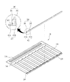
図2は、図1に示されたボトムカバー10に配置される発光モジュール280と、第2放熱部材212の一実施例を示す斜視図である。
FIG. 2 is a perspective view showing an embodiment of the
図2を参照すると、ボトムカバー10は金属材質の板状からなり、その強度を補強するために、左右方向に延長され、前方に凸状に形成される第1フォーミング部210と、第1フォーミング部210の配置方向に対して垂直に凸状に形成される第2のフォーミング部を含むことができる。第1フォーミング部210と第2フォーミング部220は、ボトムカバー10をプレス加工して形成することができる。
Referring to FIG. 2, the
第2フォーミング部220間にはヒートパイプ(heat pipe)又はヒートシンク(heat sink)形態の第1放熱部材230が設置されることができ、また、複数設けられ、互いに離隔して配置されることができる。
A first
ボトムカバー10の枠には、前方に折り曲げられて形成される枠壁240が設けられ、ボトムカバー10の内部に配置される反射シート20、導光板30、又は光学シート40が外部に離脱することを防止する。ボトムカバー10の剛性を補完するために、ボトムカバー10の背面にはHビーム(H beam)が設置されることができる。
The frame of the
図2には、図1に示されていない発光モジュール280を図示する。発光モジュール280は、ボトムカバー10の下部に配置される。発光モジュール280とボトムカバー10との間には第2放熱部材212が配置される。
FIG. 2 illustrates a
発光モジュール280は、ボトムカバー10の内側に配置される第2放熱部材212の一方の側と接触し、第2放熱部材212と結合して固定される。第2放熱部材212は、ボトムカバー10に配置され、第1放熱部材230と接触することができる。
The
具体的に、第2放熱部材212は、ボトムカバー10の一側枠壁245に接するようにボトムカバー10の内側に配置され、第1放熱部材230と接することができる。
Specifically, the second
例えば、第2放熱部材212は、「L」字状のブラケット(bracket)形態であることができる。この時、第2放熱部材212は、第1放熱部212a及び第2放熱部212bを含み、両者が互いに一体化されるように構成されることができる。
For example, the second
第1放熱部212aは、第1放熱部材230と面接触し、導光板30の入光面120と垂直になるようにボトムカバー10の内側と接する。第2放熱部212bは、第1放熱部212aに対して垂直であり、発光モジュール280と面接触することができる。
The first
具体的に、第1放熱部212aは、導光板30の入光面120と垂直になるようにボトムカバー10と接する。第2放熱部212bは、第1放熱部212aと垂直になり、導光板30の入光面120と水平になることができる。第2放熱部212bはボトムカバー10の一側枠壁245に固定され、第2放熱部212bの後面はボトムカバー10の一側枠壁245と接することができる。
Specifically, the first
発光モジュール280は、回路基板282、及び回路基板282の上に配置される光源部281を含む。発光モジュール280の少なくとも一部分は、第2放熱部材212に結合されて固定されることができる。光源部281は、LED(Light Emitting Device)又はLEDパッケージ(package)からなることができるが、これに限定されるものではない。
The
図3は、図2に示された発光モジュール280と第2放熱部材212の分解斜視図である。
FIG. 3 is an exploded perspective view of the
図3を参照すると、第2放熱部材212は、第2放熱部212bに隣接する第1放熱部212aの一領域にライン状の単一の結合溝310が形成される。結合溝310は、第2放熱部212bに接する。すなわち、ライン状の結合溝310は、第1放熱部212a及び第2放熱部212bが接する境界面に隣接する第1放熱部212a内に形成される。また、結合溝310は、第1放熱部212aの側面320に開放されるように形成されることができる。ライン状の結合溝310は、第2放熱部212bと水平であることができる。
Referring to FIG. 3, in the second
発光モジュール280は、回路基板282、及びその一面上に一列に配置される多数のLEDパッケージ(281:310−1〜310−N、N>1である自然数)で構成される。回路基板282は、バー(bar)状の矩形であることができる。以下、長さが相対的に長い回路基板282の側端を「長側端」と言い、長さが相対的に短い側端を「短側端」と言う。また、以下、各LEDパッケージ281が配置される面を回路基板282の「上面」と言い、その反対面を回路基板282の「後面」と言う。
The
多数のLEDパッケージ281は、回路基板282の第1長側端340と水平になるように配置される。この時、多数のLEDパッケージ281は、第2長側端350よりも第1長側端340にさらに隣接して配置されることができる。
The
回路基板282の第2長側端350と結合溝310はいずれもライン状であることができる。回路基板282の後面が第2放熱部212bに接するように、回路基板282の第2長側端350は結合溝310に挟み込まれる。第2長側端350が第2放熱部材212に形成された結合溝310に挟み込まれることによって回路基板282は第2放熱部材212に固定される。
Both the second
結合溝310の深さK1は、回路基板282の大きさによって多様に具現されることができる。例えば、回路基板282の第2長側端350が結合溝310に結合され、回路基板282が第2放熱部材212に安定的に固定できるように結合溝310の深さK1は第2放熱部212aの厚さmの1/2以上であり得る。
The depth K1 of the
また、回路基板282の第2長側端350が結合溝310に安定的に結合されて固定されることができるように結合溝310の幅K2は、回路基板282の第2長側端350の幅を考慮して決定されることができる。例えば、結合溝310の幅K2は、回路基板282の第2長側端350の幅と同一であることができる。
Further, the width K2 of the
一般的なバックライトユニットは、回路基板に両面テープを付着し、ボトムカバー又は放熱部材に付着する構造である。各LEDパッケージは、多量の熱を放出する熱源であるため、LEDパッケージを配置する回路基板は各LEDパッケージから放出される熱によって反りが発生し、また、その反りの度合いが大きいため、バックライトユニットの光特性が悪くなる可能性がある。 A general backlight unit has a structure in which a double-sided tape is attached to a circuit board and attached to a bottom cover or a heat dissipation member. Since each LED package is a heat source that emits a large amount of heat, the circuit board on which the LED package is arranged is warped due to the heat released from each LED package, and the degree of warpage is large, so that the backlight The light characteristics of the unit may be deteriorated.
各LEDパッケージ330−1〜330−Nから放出される熱により発生する張力が回路基板282に作用しても、実施例は、回路基板282が第2放熱部材212に形成される結合溝310に挿入される構造を有するので回路基板282の反りによる変形を抑制することができる。
Even if the tension generated by the heat released from each of the LED packages 330-1 to 330 -N acts on the
図4は、図1に示されたボトムカバー10に配置される発光モジュールと第2放熱部の他の実施例を示す斜視図である。図4に示された第2放熱部材412は、図2に示された第2放熱部材212と比較するとき、結合溝425が第1放熱部412aを貫通して形成される点を除いては互いに同一である。回路基板282の後面が第2放熱部412bに接するように回路基板282の第2長側端350が結合溝425に挟み込まれることによって発光モジュール280は第2放熱部材412に固定されることができる。
FIG. 4 is a perspective view showing another embodiment of the light emitting module and the second heat radiating portion arranged on the
図5は、図1に示されたボトムカバー10に配置される発光モジュール580と第2放熱部材512のまた他の実施例を示す斜視図であり、図6は、図5に示された発光モジュール580と第2放熱部材512の分解斜視図である。
FIG. 5 is a perspective view showing another embodiment of the
図5を参照すると、発光モジュール580は、第2放熱部材512の一方の側と接触し、第2放熱部材512と結合して固定される。第2放熱部材512は、ボトムカバー10に配置されて第1放熱部材230と接触することができる。
Referring to FIG. 5, the
第2放熱部材512は、「L」字状のブラケット形態であることができ、一体化された第1放熱部512a及び第2放熱部512bを含むことができる。
The second
第1放熱部512aは第1放熱部材230と面接触し、第2放熱部512bは発光モジュール580と面接触することができる。第1放熱部512aと第2放熱部512bは、折り曲げられた形態で配置されることができる。
The first
具体的に、第1放熱部512aは、導光板30の入光面120と垂直になるようにボトムカバー10と接し、第2放熱部512bの後面は、ボトムカバー10の一側枠壁245と接することができる。
Specifically, the first
図6に示すように、第2放熱部512bに隣接する第1放熱部512aの一領域には、互いに離隔して形成される多数の結合溝(610−1〜610−M、例えば、M=5)が形成される。この時、各結合溝610−1〜610−5は、第2放熱部512bに接し、第1放熱部512aを貫通してもよく、または、貫通しなくてもよい。
As shown in FIG. 6, in one region of the first
すなわち、各結合溝610−1〜610−Mは、第1放熱部512a及び第2放熱部512bが接する境界面に接する第1放熱部512a内に形成される。
That is, each coupling groove 610-1 to 610-M is formed in the first
発光モジュール580は、矩形の回路基板582、及びその上面に第1長側端630と水平になるように一列に配置される多数のLEDパッケージ(581:601−1〜601−N、N>1である自然数)で構成される。
The
回路基板582の第2長側端640には、第1放熱部512aに形成される各結合溝610−1〜610−5と対応するように各結合突起(620−1〜620−M、例えば、M=5)が形成される。この時、各結合溝及びこれに対応する各結合突起の数及び形態は多様に具現することができる。
In the second
回路基板582の後面が第2放熱部512bに接し、回路基板582の第2長側端640が第1放熱部512aの上面に接するように、各結合突起620−1〜620−5それぞれは、対応する結合溝に挟み込まれる。各結合突起620−1〜620−5が第2放熱部材512に形成された各結合溝610−1〜610−5に挟み込まれることによって回路基板582は、第2放熱部材512に固定される。
Each of the coupling protrusions 620-1 to 620-5 is such that the rear surface of the
回路基板582が第2放熱部材512と安定的に結合して固定できるように各結合溝610−1〜610−Mの深さ、各結合突起620−1〜620−Mの長さ、及びその数などが決定されることができる。例えば、各結合溝610−1〜610−Mの深さK1及び各結合突起620−1〜620−Mの長さは、第1放熱部512aの厚さmの1/2以上であり得る。
The depth of each coupling groove 610-1 to 610 -M, the length of each coupling protrusion 620-1 to 620 -M, and its length so that the
図7は、図1に示されたボトムカバー10に配置される発光モジュールと第2放熱部材のまた他の実施例を示す斜視図であり、図8は、図7に示された発光モジュール280と第2放熱部材712の分解斜視図である。図7に示された発光モジュール280は、図3で説明した発光モジュールと同一である。
FIG. 7 is a perspective view showing another embodiment of the light emitting module and the second heat radiating member disposed on the
図7及び図8を参照すると、発光モジュール280は、第2放熱部材712の一方の側と接触し、第2放熱部材712と結合して固定される。第2放熱部材712はボトムカバー10に配置され、第1放熱部材230と接触することができる。
Referring to FIGS. 7 and 8, the
第2放熱部材712は、「L」字状のブラケット形態であることができ、一体化された第1放熱部712a及び第2放熱部712bを含むことができる。第1放熱部712aは第1放熱部材230と面接触し、第2放熱部712bは発光モジュール280と面接触することができる。
v
具体的に、第1放熱部712aは、導光板30の入光面120と垂直になるようにボトムカバー10と接し、第2放熱部712bの後面は、ボトムカバー10の一側枠壁245と接することができる。
The second
v
Specifically, the first
第2放熱部712bと一定の距離K3だけ離隔して、第1放熱部712aの一領域上にはライン状の突部714(knoll)が形成される。ライン状の突部714は、第2放熱部712bと水平をなす。図8に示された突部714は、一つのバー状であるが、これに限定されるものではなく、互いに離隔する多数の分割された形態からなることも可能である。
A line-shaped protrusion 714 (knoll) is formed on a region of the first
回路基板282の後面が第2放熱部712bに接し、回路基板282の第2長側端350が第1放熱部712aに接するように、第2長側端350が第2放熱部712bと突部714との間の空間810に挿入される。第2長側端350が第2放熱部712bと突部714との間の空間810に挿入されることによって回路基板282は第2放熱部材712に固定されることができる。
The rear surface of the
突部714が第2放熱部712bと離隔される距離K3は、第2長側端350の幅K2を考慮して決定される。すなわち、この離隔距離K3は、第2長側端350の幅K2と同一であることができる。また、突部714の高さDは、回路基板282が第2放熱部材712に安定的に結合して固定されることを考慮して決定されることができる。
The distance K3 at which the
図9は、実施例によるバックライトユニットのボトムカバー10の内側に設けられた発光モジュール280を示す。図9を参照すると、ボトムカバー10の前面には第1放熱部材230が互いに離隔して配置されており、第1放熱部材230の下部側には第2放熱部材212が配置される。
FIG. 9 shows the
第1放熱部材230は、ボトムカバー10の第1方向、例えば、上下方向に配置され、第2放熱部材212は、ボトムカバー10の第2方向、例えば、水平方向に配置されることができる。
The first
第2放熱部材212は、第1放熱部材230と面接触する第1放熱部212aと、第1放熱部212aと垂直に配置され、その上に発光モジュール280が配置される第2放熱部212bと、を含む。
The second
第2放熱部212bの一面には発光モジュール280が配置され、前記発光モジュール280の構成を見ると、第2の放熱部212bに沿って長く配置される回路基板282と、回路基板282に互いに離隔して配置される各発光素子281と、回路基板282に設けられ、回路基板282を外部の電源装置又は印刷回路基板に連結するコネクタ283と、を含む。
The
図9では、発光素子281がLEDで構成された場合を示しているが、これに限定されるものではなく、LEDの他にCCFLのようなランプで構成されたり、又はOLEDのような有機発光素子で構成されることも可能である。発光素子281は、液晶表示パネル60及びボトムカバー10の上部のみに配置されたり、又は下部のみに配置される、いわゆる「1―エッジ(edge)」形態で構成されることができる。
Although FIG. 9 shows a case where the
発光素子281は、所望の輝度及び光の均一な分布のために、表示パネルの大きさ、すなわち、表示パネルのインチ数によってその個数が変わり得る。発光素子281は、表示パネルのインチ数の2.5〜3.5倍の個数で配置されることができる。
The number of the
図10は、図1に示された表示装置100のA−A'線断面図である。図10を参照すると、第2放熱部材212は「L」字状に形成され、第1放熱部212aは第1放熱部材230の下側に接する形態になる。
10 is a cross-sectional view taken along line AA ′ of the
第2放熱部212bは、第1放熱部212aと一体に形成され、第1放熱部212aに対して垂直又は垂直に近い角度で配置され、第2放熱部212bには発光モジュール280が配置されるが、回路基板282が第2放熱部212bに配置され、回路基板282の上に発光素子281が配置される。
The second
回路基板282は結合を通じて第2放熱部材212に固定され、その結合の形態は、図2乃至図8で説明したようである。このような結合によって発光素子281から放出される熱によって発生する回路基板282の変形(例えば、反り)を防止することができる。
The
回路基板282に電源が印加され、発光素子281から光が発散される場合、それによって派生的に熱が発生し、その熱は、第2の放熱部材212に伝導された後、第2の放熱部材212と接触している第1の放熱部材230に移動して外部に放熱される。
When power is applied to the
第2放熱部材212及び第1放熱部材230の前面には反射シート20が配置され、反射シート20の前面には導光板30が配置される。導光板30の側面(入光面)は発光素子281に隣接して配置され、発光素子281から発散される光が導光板30の内部に入っていく。
The
導光板30の内部に入ったほとんどの光は、その内部での反射、全反射及び屈折現象を経て前方に向かうようになる。ただし、後方に出る光は、反射シート20によって反射されて再び導光板30の内部に入っていく。
Most of the light that enters the
導光板30の前面には光の光学現象を誘発できる光学シート40が設けられ、光学シート40の前方には液晶表示パネル60が配置される。液晶表示パネル60の端部には軟性印刷回路基板61が連結されるが、軟性印刷回路基板61は第1固定部材51を通過してバックライトユニットの下方に延長され、軟性印刷回路基板61には印刷回路基板62が連結され、ボトムカバー10の下部に配置される。
An
トップカバー70は、液晶表示パネル60の上下左右の枠を取り囲み、印刷回路基板62、軟性印刷回路基板61及びボトムカバー10を含むバックライトユニットの上下左右の枠を取り囲み、バックライトユニットと液晶表示パネル60を結合する役割をする。
The
このように構成される実施例で、第1放熱部212aは少なくとも一つの溝又は少なくとも一つのホールが形成されることができ、発光モジュール280は第1放熱部212aに形成された少なくとも一つの溝又は少なくとも一つのホールに挿入されて固定されて、第2放熱部212bに接触されるように配置されることができる。
In the embodiment configured as described above, the first
ここで、第1放熱部212aの溝又はホールは、第2放熱部212bに隣接する第1放熱部212aの縁に形成されることができる。
Here, the groove or hole of the first
この時、第1放熱部212aの溝は、ライン状の単一の溝であってもよく、または、一定間隔を有するように配列される多数の溝であってもよい。
At this time, the groove of the first
次に、第1放熱部212aのホールは、ライン状の単一のホールであってもよく、または、一定間隔を有するように配列される多数のホールであってもよい。
Next, the holes of the first
続いて、第2放熱部212bに隣接する第1放熱部212aの縁領域に少なくとも一つの突部714が形成され、突部714は第2放熱部212bから離隔されることができる。
Subsequently, at least one
ここで、突部714は、一つからなり、第1放熱部212aと第2放熱部212bとの間の境界面に沿って並べて形成されるライン状の単一体であってもよく、多数個からなり、互いに一定間隔を有するように第1放熱部212aと第2放熱部212bとの間の境界面に沿って並べて形成されることもできる。
Here, the
そして、第2放熱部212bは、溝又はホールが形成された第1放熱部212aの縁領域に連結され、第1放熱部212aの表面に対して垂直の方向にベンディングされることができる。
The second
続いて、発光モジュール280は、第1放熱部212aの溝又はホールに挿入されて結合されるように、第1放熱部212aの溝又はホールに対応する一方の側に少なくとも一つの結合突起620−1〜620−5が形成されることができる。
Subsequently, the
このように構成される実施例は、LEDパッケージから発生する熱による基板の反りを防止することができる。 The embodiment configured as described above can prevent the substrate from being warped by heat generated from the LED package.
以上では、実施例を中心として説明したが、これは例示的なものに過ぎず、本発明の属する分野における通常の知識を有する者であれば、本発明の技術思想と範疇を逸脱しない範囲で様々な変形と修正が可能であるということが理解できる。より具体的には、本詳細な説明、図面及び請求範囲内で構成要素及び/又は組合体の構成物を変形したり修正することができる。本発明の属する分野における通常の知識を有する者であれば、構成要素及び/又は構成物の変形及び修正だけでなく、その置換の形態もよく分かるだろう
In the above description, the embodiment has been mainly described. However, this is merely an example, and a person having ordinary knowledge in the field to which the present invention belongs can be used without departing from the technical idea and category of the present invention. It can be understood that various variations and modifications are possible. More specifically, components and / or combinations of components can be varied or modified within the detailed description, drawings, and claims. Those skilled in the art to which the present invention pertains will not only understand the variations and modifications of the components and / or components, but also the mode of substitution thereof.
Claims (17)
前記ボトムカバー上に配置される発光モジュールと、
前記第1放熱部材と面接触される第1放熱部と前記第1放熱部に対して上部方向に延長される第2放熱部を含む「L」字状のブラケット(bracket)形態の、前記ボトムカバーと前記発光モジュールとの間に配置される第2放熱部材と、
前記第1放熱部の一領域上に形成され、前記第1放熱部と垂直になるように突出した突部と、を含むバックライトユニットであって、
前記発光モジュールは、前記突部と前記第2放熱部との間に少なくとも一部分が配置されるバックライトユニット。 A bottom cover including a first heat dissipating member in the form of a heat pipe or a heat sink ;
A light emitting module disposed on the bottom cover;
The bottom in the form of an “L” -shaped bracket including a first heat radiating portion in surface contact with the first heat radiating member and a second heat radiating portion extending upward with respect to the first heat radiating portion. A second heat dissipating member disposed between the cover and the light emitting module;
A projection unit formed on a region of the first heat radiating portion and projecting so as to be perpendicular to the first heat radiating portion;
The light emitting module is a backlight unit in which at least a part is disposed between the protruding portion and the second heat radiating portion.
前記反射シートの上に配置される導光板と、
前記導光板の上に配置される光学シートと、を含み、
前記第1放熱部は、前記導光板の入光面と垂直になるように前記ボトムカバーの内側の上にあり、少なくとも一つの溝が形成され、
前記第2放熱部は、前記第1放熱部に対して垂直であり、前記第1放熱部と一体であり、
前記発光モジュールは、前記第1放熱部の少なくとも一つの溝内に少なくとも一部分が配置される回路基板と、前記回路基板の上に配置される光源部とを含むことを特徴とする、請求項1ないし6のいずれかに記載のバックライトユニット。 A reflective sheet disposed on the bottom cover;
A light guide plate disposed on the reflective sheet;
An optical sheet disposed on the light guide plate,
The first heat radiating part is on the inner side of the bottom cover so as to be perpendicular to the light incident surface of the light guide plate, and at least one groove is formed.
The second heat dissipating part is perpendicular to the first heat dissipating part and integrated with the first heat dissipating part;
The light emitting module includes a circuit board at least partially disposed in at least one groove of the first heat radiating unit, and a light source unit disposed on the circuit board. The backlight unit according to any one of 6 to 6.
前記ボトムカバーの上に配置される導光板と、
前記導光板と前記ボトムカバーとの間に 配置され、少なくとも二つの溝又はホールが形成され、前記第1放熱部材と面接触される第1放熱部と、
前記第1放熱部に対して垂直であり、前記第1放熱部と一体である第2放熱部を含む「L」字状のブラケット(bracket)形態の第2放熱部材と、
前記第1放熱部の少なくとも一つの溝又はホール内に少なくとも一部分が配置される、前記第1放熱部と前記導光板との間に配置される回路基板と前記回路基板の上に配置される光源部を含む発光モジュールと、
前記導光板の上に配置される光学シートと、
前記光学シートの上部に配置されるディスプレイパネルと、を含むバックライトユニットであって、
前記回路基板に前記第1放熱部の溝又はホールと結合する少なくとも二つの結合突起を含むことを特徴とする、バックライトユニット。 A bottom cover including a first heat dissipating member in the form of a heat pipe or a heat sink ;
A light guide plate disposed on the bottom cover;
A first heat dissipating part disposed between the light guide plate and the bottom cover, wherein at least two grooves or holes are formed and in surface contact with the first heat dissipating member ;
A second heat dissipating member in the form of an “L” -shaped bracket that is perpendicular to the first heat dissipating part and includes a second heat dissipating part integral with the first heat dissipating part;
A light source disposed on the circuit board and a circuit board disposed between the first heat radiation part and the light guide plate, wherein at least a part is disposed in at least one groove or hole of the first heat radiation part. A light emitting module including a portion;
An optical sheet disposed on the light guide plate;
A backlight unit including a display panel disposed on the optical sheet,
The backlight unit according to claim 1, wherein the circuit board includes at least two coupling protrusions coupled to a groove or a hole of the first heat radiating portion.
Applications Claiming Priority (2)
| Application Number | Priority Date | Filing Date | Title |
|---|---|---|---|
| KR10-2010-0066206 | 2010-07-09 | ||
| KR1020100066206A KR101729264B1 (en) | 2010-07-09 | 2010-07-09 | A backlight unit and a display device |
Publications (3)
| Publication Number | Publication Date |
|---|---|
| JP2012018927A JP2012018927A (en) | 2012-01-26 |
| JP2012018927A5 JP2012018927A5 (en) | 2014-08-21 |
| JP5973138B2 true JP5973138B2 (en) | 2016-08-23 |
Family
ID=44786943
Family Applications (1)
| Application Number | Title | Priority Date | Filing Date |
|---|---|---|---|
| JP2011151730A Expired - Fee Related JP5973138B2 (en) | 2010-07-09 | 2011-07-08 | Backlight unit |
Country Status (5)
| Country | Link |
|---|---|
| US (1) | US8616752B2 (en) |
| EP (1) | EP2405188B1 (en) |
| JP (1) | JP5973138B2 (en) |
| KR (1) | KR101729264B1 (en) |
| CN (1) | CN102338327B (en) |
Families Citing this family (9)
| Publication number | Priority date | Publication date | Assignee | Title |
|---|---|---|---|---|
| JP5021102B1 (en) * | 2011-09-30 | 2012-09-05 | シャープ株式会社 | Liquid crystal display |
| EP2607949B1 (en) * | 2011-12-23 | 2018-06-06 | Samsung Electronics Co., Ltd | Display module and display apparatus having the same |
| WO2013121998A1 (en) * | 2012-02-17 | 2013-08-22 | シャープ株式会社 | Illumination device, display device and television receiver |
| KR101259347B1 (en) * | 2012-06-05 | 2013-04-30 | 주식회사 파인디앤씨 | Stand frame of led for backlight unit |
| JP2014086406A (en) * | 2012-10-26 | 2014-05-12 | Funai Electric Co Ltd | Display device |
| JP2014085653A (en) * | 2012-10-26 | 2014-05-12 | Funai Electric Co Ltd | Display device |
| KR101990528B1 (en) * | 2012-11-08 | 2019-06-18 | 엘지디스플레이 주식회사 | LED assembly and liquid crystal display device using the same |
| JP2014170079A (en) * | 2013-03-01 | 2014-09-18 | Funai Electric Co Ltd | Display device |
| KR102306022B1 (en) * | 2014-12-31 | 2021-09-30 | 엘지전자 주식회사 | Back light unit and display apparatus having it |
Family Cites Families (26)
| Publication number | Priority date | Publication date | Assignee | Title |
|---|---|---|---|---|
| JP3135971B2 (en) * | 1992-02-25 | 2001-02-19 | 松下電工株式会社 | Electronic time switch |
| KR100541277B1 (en) | 1998-08-26 | 2006-03-14 | 삼성전자주식회사 | Backlight Assembly of Liquid Crystal Display |
| JP2003279973A (en) | 2002-03-20 | 2003-10-02 | Kawaguchiko Seimitsu Co Ltd | Backlight attaching structure for liquid crystal display device |
| KR100959785B1 (en) * | 2003-09-16 | 2010-05-28 | 삼성전자주식회사 | Back light assembly and liquid crystal display device having the same |
| JP2005267852A (en) * | 2004-03-16 | 2005-09-29 | Sharp Corp | Backlight reflecting plate |
| JP2006208723A (en) | 2005-01-27 | 2006-08-10 | Minebea Co Ltd | Liquid crystal display device |
| US7903198B2 (en) * | 2005-05-30 | 2011-03-08 | Kyocera Corporation | Liquid crystal display device |
| JP2007163620A (en) * | 2005-12-12 | 2007-06-28 | Hitachi Displays Ltd | Liquid crystal display device and backlight device |
| JP4654920B2 (en) * | 2006-01-19 | 2011-03-23 | 三菱電機株式会社 | Light source device and liquid crystal display device |
| CN101004515A (en) * | 2006-01-21 | 2007-07-25 | 鸿富锦精密工业(深圳)有限公司 | Full run-down type backlight module |
| KR100978045B1 (en) * | 2006-03-13 | 2010-08-26 | 삼성전자주식회사 | Lyquid crystal panel assembly and lyquid crystal display having the same |
| JP4840121B2 (en) * | 2006-04-20 | 2011-12-21 | 三菱電機株式会社 | Surface light source device |
| TW200811522A (en) * | 2006-08-22 | 2008-03-01 | Chunghwa Picture Tubes Ltd | Light-source fixing structure for backlight module |
| CN101131500A (en) * | 2006-08-23 | 2008-02-27 | 中华映管股份有限公司 | Light source fixing structure of backlight component |
| JP4915911B2 (en) * | 2006-10-02 | 2012-04-11 | 株式会社 日立ディスプレイズ | Liquid crystal display |
| BRPI0721020A2 (en) * | 2007-01-22 | 2014-07-29 | Sharp Kk | REAR LIGHT DEVICE AND FLAT DISPLAY Using the same |
| TWM324216U (en) * | 2007-05-23 | 2007-12-21 | Everlight Electronics Co Ltd | LED back light module |
| KR100879772B1 (en) | 2007-09-06 | 2009-01-21 | 한성엘컴텍 주식회사 | Surface emission device having a plurality of light emission devices |
| JP5073808B2 (en) | 2008-02-28 | 2012-11-14 | シャープ株式会社 | Backlight unit and liquid crystal display device |
| JP4618310B2 (en) * | 2008-03-19 | 2011-01-26 | エプソンイメージングデバイス株式会社 | LIGHTING DEVICE, LIGHTING DEVICE ASSEMBLY METHOD, AND LIQUID CRYSTAL DISPLAY DEVICE |
| KR101322312B1 (en) | 2008-05-23 | 2013-10-25 | 엘지디스플레이 주식회사 | Liquid crystal display device |
| CN101338867B (en) * | 2008-09-01 | 2012-09-05 | 友达光电股份有限公司 | Backlight module and LCD device |
| KR101529579B1 (en) * | 2008-11-13 | 2015-06-19 | 삼성디스플레이 주식회사 | Back-light assembly, display device having the same and method of manufacturing display device |
| JP2010147012A (en) * | 2008-12-22 | 2010-07-01 | Panasonic Electric Works Co Ltd | Planar light source, and display lighting fixture |
| KR101529556B1 (en) * | 2008-12-26 | 2015-06-17 | 엘지디스플레이 주식회사 | Liquid crystal display device having good heat radiating function |
| KR20100106790A (en) * | 2009-03-24 | 2010-10-04 | 삼성전자주식회사 | Display device |
-
2010
- 2010-07-09 KR KR1020100066206A patent/KR101729264B1/en active IP Right Grant
-
2011
- 2011-06-15 EP EP11170066.2A patent/EP2405188B1/en active Active
- 2011-06-30 CN CN201110186421.4A patent/CN102338327B/en active Active
- 2011-06-30 US US13/174,037 patent/US8616752B2/en active Active
- 2011-07-08 JP JP2011151730A patent/JP5973138B2/en not_active Expired - Fee Related
Also Published As
| Publication number | Publication date |
|---|---|
| EP2405188A3 (en) | 2014-12-24 |
| KR101729264B1 (en) | 2017-05-02 |
| CN102338327B (en) | 2014-03-12 |
| CN102338327A (en) | 2012-02-01 |
| US8616752B2 (en) | 2013-12-31 |
| EP2405188A2 (en) | 2012-01-11 |
| US20120008337A1 (en) | 2012-01-12 |
| EP2405188B1 (en) | 2018-01-03 |
| JP2012018927A (en) | 2012-01-26 |
| KR20120005657A (en) | 2012-01-17 |
Similar Documents
| Publication | Publication Date | Title |
|---|---|---|
| JP5973138B2 (en) | Backlight unit | |
| JP5403579B2 (en) | Planar light source and liquid crystal display device | |
| US7287879B2 (en) | Thermal module and backlight system using the same | |
| EP2390712B1 (en) | Backlight unit and display device including the same | |
| JP2006310221A (en) | Edge input type backlight and liquid crystal display device | |
| US10281765B2 (en) | Backlight unit provided with supporter of light source unit, manufacturing method of the supporter, and display device including the backlight unit | |
| KR101975488B1 (en) | Backlight assembly and display device comprising the same | |
| KR20140123432A (en) | Backlight unit and Liquid crystal display device including the same | |
| US20110299298A1 (en) | Backlight module | |
| KR101737054B1 (en) | Backlight assembly and display apparatus having the same | |
| US20160124268A1 (en) | Display device and television receiver | |
| TWI405102B (en) | Backlight module and optical touch panel | |
| KR20140076723A (en) | Light reflector, back light unit having the same, and display device having thereof | |
| KR101712096B1 (en) | A backlight unit and a display device | |
| JP5722946B2 (en) | Back cabinet, display device, and television receiver | |
| KR102064761B1 (en) | Back light unit and display device comprising the same | |
| WO2014185483A1 (en) | Direct backlight and television receiver | |
| KR20140079682A (en) | Back light unit and display device comprising the same | |
| KR101735668B1 (en) | A backlight unit and a display device | |
| JP5726947B2 (en) | Display device and television receiver | |
| WO2016047275A1 (en) | Display device and television receiver | |
| JP5651734B2 (en) | Display device and television receiver | |
| KR101092876B1 (en) | Liquid crystal display device module | |
| JP5651736B2 (en) | Display device and television receiver | |
| JP5722945B2 (en) | Back cabinet, display device, and television receiver |
Legal Events
| Date | Code | Title | Description |
|---|---|---|---|
| RD03 | Notification of appointment of power of attorney |
Free format text: JAPANESE INTERMEDIATE CODE: A7423 Effective date: 20130725 |
|
| A521 | Written amendment |
Free format text: JAPANESE INTERMEDIATE CODE: A523 Effective date: 20140704 |
|
| A621 | Written request for application examination |
Free format text: JAPANESE INTERMEDIATE CODE: A621 Effective date: 20140704 |
|
| A131 | Notification of reasons for refusal |
Free format text: JAPANESE INTERMEDIATE CODE: A131 Effective date: 20150224 |
|
| A977 | Report on retrieval |
Free format text: JAPANESE INTERMEDIATE CODE: A971007 Effective date: 20150227 |
|
| A521 | Written amendment |
Free format text: JAPANESE INTERMEDIATE CODE: A523 Effective date: 20150522 |
|
| A131 | Notification of reasons for refusal |
Free format text: JAPANESE INTERMEDIATE CODE: A131 Effective date: 20151104 |
|
| A521 | Written amendment |
Free format text: JAPANESE INTERMEDIATE CODE: A523 Effective date: 20160112 |
|
| TRDD | Decision of grant or rejection written | ||
| A01 | Written decision to grant a patent or to grant a registration (utility model) |
Free format text: JAPANESE INTERMEDIATE CODE: A01 Effective date: 20160705 |
|
| A61 | First payment of annual fees (during grant procedure) |
Free format text: JAPANESE INTERMEDIATE CODE: A61 Effective date: 20160714 |
|
| R150 | Certificate of patent or registration of utility model |
Ref document number: 5973138 Country of ref document: JP Free format text: JAPANESE INTERMEDIATE CODE: R150 |
|
| LAPS | Cancellation because of no payment of annual fees |