JP5963243B2 - Roll holder - Google Patents
Roll holder Download PDFInfo
- Publication number
- JP5963243B2 JP5963243B2 JP2012056933A JP2012056933A JP5963243B2 JP 5963243 B2 JP5963243 B2 JP 5963243B2 JP 2012056933 A JP2012056933 A JP 2012056933A JP 2012056933 A JP2012056933 A JP 2012056933A JP 5963243 B2 JP5963243 B2 JP 5963243B2
- Authority
- JP
- Japan
- Prior art keywords
- roll holding
- self
- roll
- supporting
- holding plate
- Prior art date
- Legal status (The legal status is an assumption and is not a legal conclusion. Google has not performed a legal analysis and makes no representation as to the accuracy of the status listed.)
- Active
Links
Images
Landscapes
- Pallets (AREA)
Description
本発明は、自立可能な板状をなし、荷物としてのロールの両端面に対向配置されてそのロールを浮かせた状態に支持するロール保持盤に関する。 TECHNICAL FIELD The present invention relates to a roll holding disk that has a plate shape that can stand on its own, is opposed to both end faces of a roll as a load, and supports the roll in a floating state.
この種のロール保持盤として、自立を補助するための自立補助突部をロールに対向する前面の下端外縁部に備え、その反対側の後面は平坦になっているものが知られている。また、この種のロール保持盤は、不使用時には、寝かせた状態、即ち、横臥状態にして重ね合わされる(例えば、特許文献1参照)。 As this type of roll holding disk, a self-supporting auxiliary projection for assisting self-supporting is provided on the outer edge of the lower end of the front surface facing the roll, and the rear surface on the opposite side is flat. In addition, when this kind of roll holding disk is not used, it is laid down in a laid state, that is, lying down (see, for example, Patent Document 1).
ところで、ロール保持盤はロールと共に搬送され、その搬送先でロールが使用された後、ロール保持盤は横臥姿勢にされてパレット上に載置され、搬送元に返送されることが多い。しかしながら、上記した従来のロール保持盤では、ロール保持盤同士の横ずれを防止することができたが、ロール保持盤とパレットとの間の横ずれを防止することができず、搬送中にパレット上でロール保持盤が横ずれする事態が生じ得た。 By the way, the roll holding disk is conveyed together with the roll, and after the roll is used at the conveyance destination, the roll holding disk is placed on the pallet in a recumbent posture and returned to the conveying source in many cases. However, in the above-described conventional roll holding disk, it was possible to prevent the lateral displacement between the roll holding disks, but it was not possible to prevent the lateral displacement between the roll holding disk and the pallet. There could be a situation where the roll holding plate slips sideways.
本発明は、上記事情に鑑みてなされたもので、不使用時にパレットに乗せて安定して搬送することが可能なロール保持盤の提供を目的とする。 The present invention has been made in view of the above circumstances, and an object thereof is to provide a roll holding plate that can be stably transported on a pallet when not in use.
上記目的を達成するためになされた請求項1の発明に係るロール保持盤は、荷物としてのロールの端面を覆う板状をなしかつ、ロールの芯材の端部を支持するための溝状又は孔状の芯材支持部を備え、使用時には、自立状態でロールの両端部に配置されてロールを浮かせた状態に支持する一方、不使用時には横臥状態で桟構造の樹脂パレット上に載置されるロール保持盤において、自立状態のロール保持盤の下端外縁部から水平方向に突出してロール保持盤の自立を補助すると共に、ロール保持盤が横臥状態にされたときに、樹脂パレットのうち桟構造にて区画された区画孔に凹凸係合する第1自立補助突部と、自立状態のロール保持盤のうち第1自立補助突部より上側となる位置から水平方向に突出し、第1自立補助突部が区画孔に凹凸係合した状態で、別の区画孔に凹凸係合する第1位置決突部と、ロール保持盤のうち横臥状態で上方を向く横臥上面に形成されて、複数のロール保持盤を交互に180度旋回させて積み重ねた際に、上側のロール保持盤の第1位置決突部が凹凸係合して上下のロール保持盤同士を位置決めする第1位置決凹部とを備えたところに特徴を有する。 In order to achieve the above object, the roll holding disk according to the invention of claim 1 has a plate shape covering the end face of the roll as a load and a groove shape for supporting the end of the core of the roll. It is equipped with a hole-shaped core material support part, and when it is used, it is placed on both ends of the roll in a self-supporting state to support the roll in a floating state. In the roll holding plate, the horizontal structure protrudes from the outer edge of the lower end of the self-supporting roll holding plate to assist the self-supporting of the roll holding plate, and when the roll holding plate is in a lying state, A first self-supporting auxiliary protrusion that engages with the partition hole defined by the projection and the protrusion, and a first self-supporting auxiliary protrusion that protrudes in a horizontal direction from a position above the first self-supporting auxiliary protrusion of the self-supporting roll holding disc. Part is uneven in the partition hole In this state, the first positioning protrusion that engages with the other partition hole is formed on the side surface of the roll holding plate that faces upward in the recumbent state, and the plurality of roll holding plates are alternately rotated 180 degrees. When stacked, the first positioning protrusions of the upper roll holding disk are provided with a first positioning recess that positions the upper and lower roll holding disks by engaging the concave and convex portions .
請求項2の発明は、請求項1に記載のロール保持盤において、自立状態のロール保持盤の下端外縁部から第1自立補助突部と反対側の水平方向に突出してロール保持盤の自立を補助する第2自立補助突部を備えたところに特徴を有する。
請求項3の発明は、請求項2に記載のロール保持盤において、ロール保持盤のうち第2自立補助突部の裏側に形成された第2位置決凹部と、第2自立補助突部の先端に設けられて、複数のロール保持盤を交互に180度旋回させて積み重ねた際に、2つ上のロール保持盤の第2位置決凹部と凹凸係合する第2位置決突部とを備えたところに特徴を有する。
According to a second aspect of the present invention, in the roll holding disk according to the first aspect, the roll holding disk protrudes in a horizontal direction opposite to the first self-supporting auxiliary protrusion from the outer edge of the lower end of the self-supporting roll holding disk. It is characterized in that it is provided with a second self-supporting auxiliary protrusion to assist.
According to a third aspect of the present invention, in the roll holding disk according to the second aspect, a second positioning recess formed on the back side of the second self-supporting auxiliary protrusion and a tip of the second self-supporting auxiliary protrusion of the roll holding disk Provided with a second positioning protrusion that engages with the second positioning recess of the upper two roll holding disks when the plurality of roll holding disks are alternately rotated 180 degrees and stacked. It has features.
請求項4の発明は、請求項1乃至3の何れか1の請求項に記載のロール保持盤において、横臥上面に陥没形成されて、ロール保持盤の自立状態で第1位置決凹部から鉛直方向上方に延びた溝状をなし、複数のロール保持盤を交互に180度旋回させて積み重ねた際に、上側のロール保持盤の第1位置決突部を第1位置決凹部に案内することが可能な積上ガイド溝を備えたところに特徴を有する。 According to a fourth aspect of the present invention, there is provided the roll holding plate according to any one of the first to third aspects, wherein the roll holding plate is formed in a recessed manner on the upper surface of the recumbent, and is perpendicular to the first positioning recess in the self-supporting state of the roll holding plate. When a plurality of roll holding discs are alternately rotated by 180 degrees and stacked, the first positioning protrusion of the upper roll holding disc can be guided to the first positioning concave portion. It is characterized by the fact that it is provided with a possible lifting guide groove.
請求項5の発明は、請求項1乃至4の何れか1の請求項に記載のロール保持盤において、第1自立補助突部は、複数横並びに設けられ、ロール保持盤が横臥状態にされたときに、樹脂パレットのうち桟構造で区画された複数列の区画孔群のうち予め設定した特定列の区画孔群への凹凸係合は許容されるが、その特定列以外の列の区画孔群への凹凸係合が規制されるように構成されたところに特徴を有する。 According to a fifth aspect of the present invention, in the roll holding plate according to any one of the first to fourth aspects, a plurality of first self-supporting auxiliary protrusions are provided side by side, and the roll holding plate is in a recumbent state. Sometimes, the concave / convex engagement with a predetermined row of partition holes among a plurality of rows of partition holes of the resin pallet divided by the crosspiece structure is allowed, but the partition holes of rows other than the specific row It is characterized in that it is configured so that the uneven engagement with the group is restricted.
[請求項1,2,3の発明]
本発明のロール保持盤は、不使用時には横臥状態で樹脂パレット上に載置されるが、その際、ロール保持盤の第1自立補助突部を樹脂パレットのうち桟構造で区画された区画孔に凹凸係合させることで、パレットに対するロール保持盤の横ずれが防止される。これにより、ロール保持盤をパレットに乗せて安定した搬送を行うことが可能になる。しかも、その第1自立補助突部は、ロール保持盤の外縁部に配置されているので、第1自立補助突部と区画孔とを目視しながらそれらの凹凸係合作業を容易に行うことができる。また、その第1自立補助突部は、ロール保持盤の自立の補助になるので、ロール保持盤による荷物の保持も安定する。
[Inventions of Claims 1 , 2 and 3 ]
When the roll holding disk of the present invention is not used, it is placed on the resin pallet in a recumbent state. At this time, the first self-supporting auxiliary protrusion of the roll holding disk is partitioned by the crosspiece structure of the resin pallet. By engaging the projections and depressions with each other, lateral displacement of the roll holding disc with respect to the pallet is prevented. Thereby, it becomes possible to carry the stable conveyance by placing the roll holding plate on the pallet. And since the 1st self-supporting auxiliary | assistant protrusion is arrange | positioned at the outer edge part of a roll holding | maintenance board, those uneven | corrugated engagement operations can be easily performed while visually observing the 1st self-supporting auxiliary | assistant protrusion and a partition hole. it can. Further, since the first self-supporting auxiliary protrusion is used to assist the roll holding plate to stand on its own, the holding of the load by the roll holding plate is also stabilized.
さらに、本発明のロール保持盤は、自立状態における上下の両端部から水平方向に第1自立補助突部と第1位置決突部とが突出した構造になっている。そして、横臥状態で樹脂パレット上に載置すると、第1自立補助突部と第1位置決突部の両方が桟構造の樹脂パレットの区画孔に凹凸係合する。これにより、パレットに対するロール保持盤の横ずれがより一層確実に防止される。また、不使用のロール保持盤が複数存在する場合には、樹脂パレット上に複数のロール保持盤を交互に180度旋回させて積み重ねていけばよい。すると、上側のロール保持盤の第1位置決突部が下側のロール保持盤の第1位置決凹部に凹凸係合し、上下のロール保持盤同士も位置決めされる。これにより、樹脂パレットとロール保持盤との間の横ずれ防止に加えて、上下のロール保持盤同士の横ずれも防止され、複数のロール保持盤をパレットに乗せた状態で安定して搬送することが可能になる。 Furthermore, the roll holding disk of the present invention has a structure in which the first self-supporting auxiliary protrusion and the first positioning protrusion protrude in the horizontal direction from the upper and lower ends in the self-supporting state. Then, when placed on the resin pallet in a recumbent state, both the first self-supporting auxiliary protrusion and the first positioning protrusion protrude into and out of the partition hole of the cross-shaped resin pallet. Thereby, the lateral shift | offset | difference of the roll holding disk with respect to a pallet is prevented more reliably. Further, when there are a plurality of unused roll holding discs, the plurality of roll holding discs may be alternately rotated 180 degrees and stacked on the resin pallet. Then, the first positioning protrusion of the upper roll holding disk engages with the first positioning recess of the lower roll holding disk, and the upper and lower roll holding disks are also positioned. As a result, in addition to preventing lateral displacement between the resin pallet and the roll holding plate, lateral displacement between the upper and lower roll holding plates is also prevented, and a plurality of roll holding plates can be stably conveyed in a state of being placed on the pallet. It becomes possible.
なお、不使用時に複数のロール保持盤を積み上げたときに、上側のロール保持盤の第1自立補助突部が下側のロール保持盤の側方に配置されるようにしてもよいし、上側のロール保持盤の第1自立補助突部が下側のロール保持盤のロール支持溝内に受容されるようにしてもよい。また、ロール保持盤の横臥上面に、第1自立補助突部と凹凸係合可能な補助凹部を設けておき、不使用時に複数のロール保持盤を積み上げたときに、上側のロール保持盤の第1自立補助突部が下側のロール保持盤の補助凹部に凹凸係合するようにしてもよい。 When a plurality of roll holding discs are stacked when not in use, the first self-supporting auxiliary protrusion of the upper roll holding disc may be arranged on the side of the lower roll holding disc. The first self-supporting auxiliary protrusion of the roll holding plate may be received in the roll support groove of the lower roll holding plate. Further, the lying upper surface of the roll holding plate, may be provided a first free-standing auxiliary protrusion and irregularities engageable auxiliary recess, when stacked a plurality of roll holding plate when not in use, the upper roll retaining disc first One self-supporting auxiliary protrusion may be engaged with the auxiliary concave portion of the lower roll holding disk.
[請求項4の発明]
請求項4の構成では、横臥状態のロール保持盤の上に別のロール保持盤を積み上げる際に、積上ガイド溝に第1位置決突部を受容させた状態で上側のロール保持盤を下側のロール保持盤に対してスライドさせると、第1位置決突部が第1位置決凹部に案内されて凹凸係合する。これにより、ロール保持盤の上に別のロール保持盤を積み上げる作業を効率よく行うことができる。
[Invention of claim 4 ]
In the configuration of claim 4 , when another roll holding plate is stacked on the roll holding plate in a recumbent state, the upper roll holding plate is lowered with the first positioning protrusion received in the loading guide groove . When it is slid with respect to the roll holding plate on the side, the first positioning protrusion is guided by the first positioning recess to engage with the concave and convex portions. Thereby, the operation | work which piles up another roll holding disk on a roll holding disk can be performed efficiently.
[請求項5の発明]
請求項5の構成では、横臥状態のロール保持盤を樹脂パレットの上に載置する際に、樹脂パレットにおける特定列の区画孔群には、ロール保持盤の第1自立補助突部群の凹凸係合が許容されるが、その特定列以外の列の区画孔群への凹凸係合は規制されるので、ロール保持盤が樹脂パレット上の不正規位置に載置されることを防ぐことができる。
[Invention of claim 5 ]
In the structure of Claim 5 , when mounting the roll holding disk in a recumbent state on a resin pallet, the partition hole group of the specific row | line | column in a resin pallet has the unevenness | corrugation of the 1st self-supporting auxiliary | assistant protrusion part group of a roll holding disk . Engagement is allowed, but uneven engagement with the partition hole group in a row other than the specific row is restricted, so that it is possible to prevent the roll holding disc from being placed at an irregular position on the resin pallet. it can.
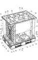
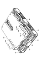
以下、本発明の一実施形態を図1〜図18に基づいて説明する。図1には、本実施形態の1対のロール保持盤50,50が、荷物としてのロール80を保持しかつケース10Kに収容された状態が示されている。また、そのケース10Kは、樹脂パレット83(以下、単に「パレット83」という)上にバンド99にて固定されている。なお、図1には、ケース10Kの一部が2点鎖線で示されており、図2には、ケース10Kを実線で示した状態が示されている。
Hereinafter, an embodiment of the present invention will be described with reference to FIGS. FIG. 1 shows a state in which a pair of
図3に示すように、ロール80は、円筒状の芯材81にシート(例えば、紙、樹脂フィルム等)を巻き付けてなる。また、芯材81の両端部は、ロール80のうち芯材81を除いたロール本体82の両端面中央から突出している。なお、本実施形態では、ロール本体82の軸長がロール本体82の直径より大きくなっている。
As shown in FIG. 3, the
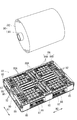
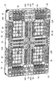
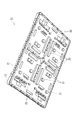
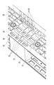
パレット83は、平面略長方形のデッキボード84の下面に複数の桁部85を備えた構造になっている。デッキボード84は、全体が上下に貫通した区画孔を有する桟構造(メッシュ構造)をなしている。また、デッキボード84の外縁部と縦横の中心線とに沿った部位には、比較的強度が大きな上面強化部84Aが備えられ、デッキボード84の全体で上面強化部84Aが「田」の字形状になっている。そして、デッキボード84のうち上面強化部84Aに囲まれた四角形の4つの領域には、上面強化部84Aより区画孔の大きな格子部84Bが備えられている。なお、上面強化部84Aのうちデッキボード84の長辺と平行に延びた1対の外縁部の上面強化部84Aは、他の上面強化部84Aに比べて幅狭になっている。
The
桁部85は、デッキボード84のうち上面強化部84A,84A同士の交差位置に配置されている。即ち、桁部85は、デッキボード84の四隅と、デッキボード84の各外縁部における各中央部と、デッキボード84の平面形状における図心との計9箇所に配置されている。また、各桁部85は、パレット83の上下方向全体に亘って延びた桁部筒壁90を内側から補強壁にて補強した構造になっている。
The
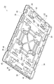
図5に示すように、縦横の何れかの方向で隣り合った桁部85,85の下端部の間には、下面強化梁86が差し渡され、その下面強化梁86の全体が「田」の字形状になっている。そして、下面強化梁86に囲まれた四角形の4つの領域が、上記した格子部84Bに相当する構造体を有しない下面窓83Wになっている。また、パレット83の各側面において、四方をデッキボード84と1対の桁部85,85と下面強化梁86とに囲まれた部分がフォーク挿入口87をなし、何れかの側面の1対のフォーク挿入口87,87からフォークリフトのフォークを挿入することができる。
As shown in FIG. 5, the lower
パレット83の上面のうち所要な部位に関しては以下の通りである。図3に示すように、パレット83のうち上面強化部84Aが「十」の字状に交差した部分の桁部85と、「十」の字の4つの各先端に位置した桁部85との間を連絡する各部位には、それぞれ3つずつの上面溝88Aが形成されている。それら3つの上面溝88Aは、上面強化部84Aの長手方向に沿って延びかつ上面強化部84Aの幅方向で横並びになっている。そして、これら4組3つずつの上面溝88Aのうち、各組の両外2つずつの上面溝88A,88Aに、後述する底盤11の第1下面位置決突部20が凹凸係合する。
The required parts of the upper surface of the
デッキボード84の長辺方向H2(図3及び4参照)の両端部中央に位置した桁部85,85における桁部筒壁90の内側上部は、図4に拡大して示すように、デッキボード84の短辺方向H1(図4参照)と平行な複数の桁内横壁97によって、例えば、5つの列に区画されている。これら5つの列をデッキボード84の長辺方向H2の中央側から順番に第1〜第5の列と呼ぶとすると、第4の列は、デッキボード84の長辺方向H2と平行な桁内縦壁96によって2つの区画孔94に区画されている。また、それ以外の第1〜第3及び第5の列は、複数の桁内縦壁96によって4つずつの区画孔91(又は92,93,95)に区画されている。そして、本発明の「特定列」に相当する第2の列の4つの区画孔92のみに、ロール保持盤50の後述する4つの後側自立補助突部58(図7参照)が凹凸係合可能になっている。
As shown in an enlarged view in FIG. 4, the
即ち、第3、第4、第5の列は、第2の列よりデッキボード84の長辺方向H2の間隔が小さい。また、第1、第3及び第5の列では、桁内縦壁96と桁内横壁97の縁部から補強リブ98が張り出していて、隣り合った区画孔91,91同士等の間隔が区画孔92,92同士の間隔より広くなっている。これらにより、第1、第3、第4、第5の列の区画孔91,93,94,95に対しては、それら開口縁に後側自立補助突部58の一部が干渉して、複数の後側自立補助突部58の全体が凹凸係合できないようになっている。
That is, the third, fourth, and fifth rows have a smaller interval in the long side direction H2 of the
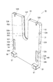
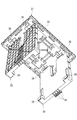
ロール保持盤50,50を収容するケース10Kは、図2に示すように、筒形側壁70と、その筒形側壁70の下面開口及び上面開口を閉塞する底盤11及び天盤31とからなる。筒形側壁70は、例えば、樹脂板、段ボールで構成され、断面長方形の角筒状になっている。一方、底盤11及び天盤31は、樹脂シートの真空成形品であって、全体がパレット83の平面形状に対応した長方形の板状をなしている。そして、図8に示すように、底盤11の上面外縁部に、筒形側壁70の下端部の外側に嵌合する側壁下端嵌合部13が膨出形成され、図10に示すように、天盤31の下面外縁部に、筒形側壁70の下端部の外側に嵌合する側壁上端嵌合部33が膨出形成されている。
As shown in FIG. 2, the
底盤11の下面には、パレット83の上面との間で横ずれを防止するための構造が備えられている。具体的には、図9に示すように、底盤11の下面には、前述のパレット83(図3参照)の上面溝88Aに凹凸係合する複数の第1下面位置決突部20と、パレット83の上面強化部84Aの所定の区画孔に凹凸係合する四角形の第2下面位置決突部21と、パレット83における区画孔91(図4参照)に凹凸係合する四角形の第3下面位置決突部23とが膨出形成されている。
On the lower surface of the
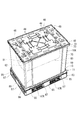
また、ケース10K上にパレット83を積み上げた際の横ずれを防ぐために、天盤31の上面には、図1に示すように、パレット83の下面の4つの下面窓83W(図5参照)に凹凸係合する4つの第1上面位置決突部44と、パレット83の桁部85下面の格子孔85K(図5参照)に凹凸係合する第2上面位置決突部45とが膨出形成されている。
In addition, in order to prevent lateral displacement when the
なお、図1に示すように、天盤31の4辺の外縁部におけるそれぞれの両端部寄り位置には、側壁上端嵌合部33の外側面を構成する外側壁部の上端をV字状に切除してバンド受容溝48が形成されている。
In addition, as shown in FIG. 1, the upper end of the outer side wall part which comprises the outer side surface of the side wall upper
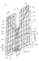
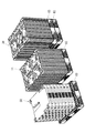
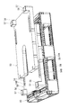
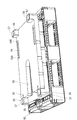
さて、ロール保持盤50は、合成樹脂の射出成形品であって、図6に示すように、全体が長方形の板状をなし、長手方向を縦にして自立させた状態で使用される。また、不使用時には、図13に示すようにロール保持盤50は、寝かせた状態、即ち、横臥状態でパレット83上に載置され、不使用のロール保持盤50が複数存在する場合には、それら複数のロール保持盤50が交互に180度向きを変えて積み重ねられる。以下、ロール保持盤50,50のうち自立状態で互いに対向する面(本発明の「横臥上面」に相当する)を「前面」と呼び、その反対側の面を「後面」と呼ぶと共に、自立状態のロール保持盤50の上下方向及び左右方向(横方向)を、単に、ロール保持盤50の上下方向及び左右方向(横方向)と呼ぶこととする。
Now, the
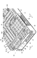
図7に示すように、ロール保持盤50は、略長方形の主平板51の後面に後面リブ53を一体成形して備えている。また、ロール保持盤50の左右方向の中央には、上端部から上下方向の中央部に亘って芯材支持溝55(本発明の「芯材支持部」に相当する)が形成されている。そして、主平板51の外縁部及び芯材支持溝55の内縁部から後面側に突出した包囲壁52によって後面リブ53全体が囲まれている。後面リブ53は、複数の後面横リブ53Aと複数の後面縦リブ53Bと複数の後面筋交いリブ53Xとからなり、複数の後面横リブ53A及び後面縦リブ53Bによって後面リブ53全体が格子状になっている。また、後面筋交いリブ53Xは、ロール保持盤50の各角部寄り位置の間を対角線に沿って僅かに屈曲しながら延びて、ロール保持盤50全体で「X」の文字状になっている。
As shown in FIG. 7, the
芯材支持溝55の内側下端部は、半円形に湾曲した湾曲部55Cをなし、その芯材支持溝55の1対の上端部に鉛直方向と平行になった1対の鉛直導入部55B,55Bが備えられている。また、芯材支持溝55の内面のうち1対の鉛直導入部55B,55Bより上側部分は、上方に向かうに従って互いに徐々に離間するように傾斜した傾斜導入部55Aが備えられている。また、芯材支持溝55の内面の上端縁からは直動規制鍔55Fが内側に張り出している。
The inner lower end portion of the core
芯材支持溝55の鉛直下方では、その他の部分に比べて後面縦リブ53B,53B同士の間隔が狭くなって、強度アップが図られている。また、芯材支持溝55の鉛直下方のうち特に最下端の後面横リブ53Aと下辺の包囲壁52との間では、その上方側よりさらに後面縦リブ53B同士の間隔が狭くなっていて、それら狭い間隔で横並びになった後面リブ53群の下端部から複数の後側自立補助突部58(本発明の「第1自立補助突部」に相当する)が後方に突出している。
In the vertically lower part of the core
具体的には、各後面リブ53の後縁部から突片58Tが突出していて、それら突片58Tの上面が、後面リブ53の後縁部のうち上下方向の中間位置から斜め下方に傾斜して延び、突片58Tの下面が、ロール保持盤50の下辺の包囲壁52における下面と面一になって後方に延びている。また、突片58Tの後面は、突片58Tの上面及び下面の後端部の間で鉛直に延びている。そして、このような形状の突片58Tが、例えば8つ設けられて隣り合った4ペアの突片58T,58Tに分けられ、各ペアの突片58T,58Tの後縁と上縁との間が突片間連絡壁58Sによって連絡されて、4つの後側自立補助突部58が構成されている。
Specifically, projecting pieces 58T protrude from the rear edge portions of the
なお、各後側自立補助突部58の内部では、後面縦リブ53B,53Bの後縁部同士の間が内部区画壁58Aによって閉塞され、それら内部区画壁58Aより前側には、内部区画壁58Aにて連絡された1対の後面縦リブ53B,53Bの間の空間を下方に開放する下面開口58Bが包囲壁52に貫通形成されている。
In addition, inside each rear side self-supporting
図6に示すように、ロール保持盤50の下端の横方向における両端部からは、前方に前側自立補助突部56,56(本発明の「第2自立補助突部」に相当する)が突出している。各前側自立補助突部56は、角柱状をなし、前側自立補助突部56の下面は、ロール保持盤50の下辺の包囲壁52の下面と面一になっている。また、前側自立補助突部56の一側面は、ロール保持盤50の側辺の包囲壁52における外面と面一になっている。また、各前側自立補助突部56の前端面には、位置決突部57(本発明の「第2位置決突部」に相当する)が形成されている。その位置決突部57は、ロール保持盤50の後面の下側角部で後面横リブ53A、後面縦リブ53B及び包囲壁52によって四方を囲まれた格子孔53M(図7参照。本発明の「第2位置決凹部」に相当する。以下、「下端角部孔53M」という)の丁度反対側に位置して、その下端角部孔53Mと同じ形状になっている。
As shown in FIG. 6, front self-supporting
図7に示すように、ロール保持盤50の後面における上側の両角部の近傍には、積上位置決突部59,59(本発明の「第1位置決突部」に相当する)が設けられている。各積上位置決突部59は、円筒状をなし、ロール保持盤50の上辺及び側辺の包囲壁52から僅かに内側にずれた位置に配置され、主平板51の後面から立ち上がって後面リブ53より後方に突出している。
As shown in FIG. 7, in the vicinity of the upper corners on the rear surface of the
ロール保持盤50のうち積上位置決突部59,59の下方には、筒部59K,59Kが設けられている。筒部59Kは、後面リブ53より小さい突出量で主平板51の後面から後方に突出した円筒状をなしている。また、筒部59Kは、後端部が閉塞される一方、前端部がロール保持盤50の前面側で開放していて、それら筒部59K,59Kの内側が積上位置決凹部54B,54B(図6参照。本発明の「第1位置決凹部」に相当する。)になっている。そして、図13に示すように、複数のロール保持盤50を寝かせて交互に180度向きを変えて積み上げた際に、上側のロール保持盤50の積上位置決突部59,59が、下側のロール保持盤50の積上位置決凹部54B,54Bに凹凸係合する。
図6に示すように、ロール保持盤50の前面には、積上位置決凹部54B,54Bの開口の上方に延びた積上ガイド溝54,54が形成されている。各積上ガイド溝54は、積上位置決凹部54Bの内径と同じ幅をなし、積上ガイド溝54の上端部には、主平板51の前面から積上ガイド溝54の奥面に向かって徐々に傾斜した傾斜面54Aが備えられている。また、積上ガイド溝54内の両側部には、主平板51の前面との間の段差面54D,54Dが備えられている。
As shown in FIG. 6, stacking
なお、ロール保持盤50の両側面における上下方向の複数位置には角溝状の複数のバンド受容溝52Aが陥没形成されている。また、ロール保持盤50の上面における横方向の両端寄り位置には、バンド受容溝52Aより幅狭でかつ深いポール受容溝52B,52Bが陥没形成されている。
In addition, a plurality of square groove-shaped
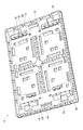
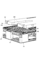
図1に示すように、1対のロール保持盤50,50は、互いに前面を対向させた状態で、底盤11の長手方向の両端寄り位置に設けた保持盤載置領域R1,R1(図8参照)に載置される。その際、ロール保持盤50を底盤11上で位置決めするために、底盤11の上面には、各保持盤載置領域R1の近傍に保持盤後側位置決突部16と保持盤前側位置決突部19とが膨出形成されている。具体的には、保持盤前側位置決突部19は、保持盤載置領域R1より底盤11における長手方向の中央側に配置される一方、保持盤後側位置決突部16は、保持盤載置領域R1を挟んで保持盤前側位置決突部19に対向配置され、これら互いに対向した保持盤後側位置決突部16及び保持盤前側位置決突部19が各保持盤載置領域R1毎に2組ずつ設けられている。そして、保持盤載置領域R1にロール保持盤50が載置されると、ロール保持盤50が互いに対向する保持盤後側位置決突部16と保持盤前側位置決突部19との間で挟まれると共に、1対の保持盤前側位置決突部19,19がロール保持盤50における1対の前側自立補助突部56,56の間に挟まれる。これにより、ロール保持盤50が底盤11の長手方向と短手方向の両方向で位置決めされる。
As shown in FIG. 1, the pair of
天盤31の長手方向における両端寄り位置には、底盤11上に対向配置された1対のロール保持盤50,50の上面を当接させる保持盤当接領域R2,R2が設けられている。そして、各保持盤当接領域R2の近傍には、ロール保持盤50を位置決めするための1対の保持盤後側位置決突部36,36と1対の保持盤前側位置決突部39,39とが膨出形成されている。そして、図11に示すように、各ロール保持盤50の上端部が保持盤前側位置決突部39と保持盤前側位置決突部36とに挟まれて、ロール保持盤50,50の上端部同士の間が一定間隔に保持される。
At positions closer to both ends in the longitudinal direction of the
本実施形態のロール保持盤50の構成に関する説明は以上である。次に、このロール保持盤50の作用効果について説明する。ロール80をロール保持盤50にて保持してケース10K内に収容するには、図1に示すように、パレット83上に底盤11を載置し、その底盤11の保持盤載置領域R1,R1(図8参照)に1対のロール保持盤50,50を載置する。すると、底盤11に備えた保持盤後側位置決突部16及び保持盤前側位置決突部19によって1対のロール保持盤50,50が底盤11上で二次元的に位置決めされて自立した状態になる。
The description regarding the structure of the roll holding |
次いで、ロール80のうち円筒状の芯材81の内部に図示しないシャフトを挿通して芯材81の両端部から突出させる。そして、そのシャフトの両端部をロープで吊り、1対のロール保持盤50,50の上方から芯材支持溝55,55内に芯材81の両端部を降下させる。すると、芯材81の両端部が芯材支持溝55の傾斜導入部55A,55A(図6参照)によってロール保持盤50の左右方向の中心に案内され、鉛直導入部55B,55B(図6参照)の間を通って芯材支持溝55の下端部の湾曲部55C(図6参照)に収まる。これにより、ロール80が1対のロール保持盤50,50によって底盤11から浮いた状態に保持される。また、ロール保持盤50は、後側自立補助突部58及び前側自立補助突部56によって自立を補助されているので振動や芯材81の衝突等を受けても容易に倒れるようなことはなく、ロール80の芯材支持溝55内への降下作業をスムーズに行うことができる。
Next, a shaft (not shown) is inserted into the
次いで、1対のロール保持盤50,50の上方からそれらの外側に筒形側壁70を挿通して、筒形側壁70の下端部を底盤11の側壁下端嵌合部13の内側に嵌合する。そして、筒形側壁70の上端部に天盤31を被せて、天盤31における側壁上端嵌合部33の内側に筒形側壁70の上端部を嵌合する。次いで、1対のバンド99,99にてケース10Kをパレット83に固定する。そのためには、1対のバンド99,99をパレット83のフォーク挿入空間87K,87K(図2参照)に挿通し、天盤31の上面に巻き付ければよい。その際、バンド99の一部をバンド受容溝48内に収めることで、バンド99の位置ずれを防ぐことができる。以上により、ロール80をロール保持盤50にて保持してケース10K内に収容する作業が完了する。
Next, the
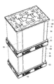
図12に示すように、パレット83に固定したケース10Kを複数積み上げてもよい。すると、積み上げられたパレット83の下面窓83W(図5参照)等に、下側のケース10Kの上面の第1上面位置決突部44等(図1参照)が凹凸係合する。これにより、パレット83と共にケース10Kを複数積み上げた状態で横ずれが防がれて、安定した搬送が可能になる。
As shown in FIG. 12, a plurality of
ケース10Kは、不使用時に嵩張らないようにするために、底盤11と天盤31と筒形側壁70とに分けられる。そして、図13に示すように、複数の底盤11と複数の天盤31とが、それぞれ別々のパレット83,83の上に積み上げられる。なお、天盤31に関しては、パレット83の上に別のパレット83を上下を逆転させて載置し、その上に天盤31を上下を逆転させた状態で積み上げられる。
The
さて、ロール保持盤50は、不使用時には、後面を下方に向けた横臥状態にして、交互に180度向きを変えて積み上げられる。その最初の1つのロール保持盤50をパレット83上に載置する作業は、以下の通りである。即ち、例えば、自立状態のロール保持盤50の両側部を把持して、自立状態のままパレット83の長手方向における一端寄り位置に載置する。そして、ロール保持盤50の後面をパレット83の中央側に向けた状態とし、後側自立補助突部58群をパレット83の長手方向の一端部中央の桁部85上に配置する。その際、ロール保持盤50の後面に備えた4つの後側自立補助突部58の先端を、桁部85内の特定列である第2の列の区画孔92群の上方に位置合わせする。そして、ロール保持盤50の下端部を中心にしてロール保持盤50の後面が下方を向くように傾ける。すると、後側自立補助突部58群が桁部85における第2の列の区画孔92群に凹凸係合し、ロール保持盤50の下端部がパレット83に対して位置決めされる。
Now, when not in use, the
ここで、もし後側自立補助突部58の先端部が、桁部85内の第2の列以外の列の区画孔91,93,94,95上に誤って配置されると、ロール保持盤50を傾けて後側自立補助突部58をそれら区画孔91,93,94,95に突入させようとした際に、後側自立補助突部58と区画孔91,93,94,95の開口縁とが干渉して、パレット83上におけるロール保持盤50の配置が誤りであったことに気づく。また、後側自立補助突部58群は、ロール保持盤50の外縁部に配置されているので、後側自立補助突部58群と区画孔92群とが正しく凹凸係合するか否かを目視確認することができ、それらの凹凸係合作業を容易に行うことができる。
Here, if the front end portion of the rear-side self-supporting
後側自立補助突部58群が桁部85の第2の列の区画孔92群に正しく凹凸係合すると、ロール保持盤50は、パレット83に対する正規位置に位置決めされ、ロール保持盤50の後面をパレット83の上面に重ねたときに、ロール保持盤50の後面の1対の積上位置決突部59,59がパレット83における格子部84Bの所定の区画孔84C(図16参照)に凹凸係合する。また、ロール保持盤50は、パレット83に対する正規位置に位置決めされると、例えば、ロール保持盤50の重心がパレット83の中央部に位置して、パレット83をフォークで持ち上げた際に、重心のバランスが好適な状態になる。以上により、ロール保持盤50をパレット83の上に載置する作業が完了する。
When the rear side self-supporting
なお、パレット83上にロール保持盤50を載置する作業は、上記した方法以外に、例えば、作業者がロール保持盤50の両側部を把持しかつ後側自立補助突部58群が作業者側に位置するようにしてロール保持盤50を横臥状態にしてから図14に示すようにパレット83の上方に運び、パレット83上に降下してもよい。そして、ロール保持盤50を降下する際に、後側自立補助突部58群を目視しながらパレット83の第2の列の区画孔92群に凹凸係合させればよい(図15参照)。そうすれば、ロール保持盤50がパレット83に対する正規位置に位置決めされ、作業者から目視不能な位置にある積上位置決突部59,59がスムーズに格子部84Bにおける区画孔84C,84Cに凹凸係合する。
In addition to the above-described method, the work of placing the
パレット83上に載置されたロール保持盤50上に更に別のロール保持盤50を載置するには、以下の通りである。即ち、下側のロール保持盤50に対して上側のロール保持盤50を180度向きを変え、上側のロール保持盤50の積上位置決突部59,59を下側のロール保持盤50の上面に載置する。そして、上下のロール保持盤50,50の左右方向の位置を一致させた状態で上側のロール保持盤50を押していくと、上側のロール保持盤50の積上位置決突部59,59の先端が下側のロール保持盤50における積上ガイド溝54,54に係合し、上側のロール保持盤50をさらに押して行くと、積上位置決突部59,59が積上ガイド溝54,54に案内されて、積上位置決凹部54B,54Bに凹凸係合する。そして、上側のロール保持盤50から作業者が手を離せば、図18に示すように、上側のロール保持盤50の一端面が下側のロール保持盤50の前側自立補助突部56,56の側面に重ねられ、上側の後側自立補助突部58群が下側のロール保持盤50の側方に位置した状態になって、ロール保持盤50,50同士の積み上げが完了する。
In order to place another
また、ロール保持盤50の上に重ねたロール保持盤50の上に、更に別のロール保持盤50を同様の作業で積み上げると、2つ下のロール保持盤50の位置決突部57が、ロール保持盤50の下面の下端角部孔53M(図7参照)に凹凸嵌合し、積上位置決突部59と積上位置決凹部54Bとの凹凸嵌合と協働してロール保持盤50,50同士の位置ずれを防ぐことができる。なお、積み重ねられた複数のロール保持盤50から一番上のロール保持盤50を取り出すには、一番上のロール保持盤50を持ち上げて積上位置決突部59,59を積上位置決凹部54B,54Bから抜いてから、下側のロール保持盤50の積上ガイド溝54,54内に仮置きする。そして、積み上げ時の作業とは逆に、上側のロール保持盤50を手前に引きずる。すると、積上位置決突部59,59が積上ガイド溝54,54の一端に傾斜面54A,54Aに摺接して、スムーズに積上ガイド溝54,54から離脱する。そして、上側のロール保持盤50を横臥状態のままで持ち上げるか、立ててから持ち上げ、所定の場所に運べばよい。
Further, when another
上記したように本実施形態のロール保持盤50では、不使用時には横臥状態でパレット83上に載置されるが、その際、ロール保持盤50の後側自立補助突部58群をパレット83の桁部85における特定列の区画孔92群に凹凸係合させることで、パレット83に対してロール保持盤50が正規位置に位置決めされた状態で横ずれが防止される。これにより、ロール保持盤50をパレット83に乗せた状態で安定した搬送が可能になる。しかも、その後側自立補助突部58群は、ロール保持盤50の外縁部に配置されているので、後側自立補助突部58群と区画孔92群とを目視しながらそれらの凹凸係合作業を容易に行うことができる。さらに、後側自立補助突部58群は、ロール保持盤50の自立の補助になるので、自立状態のロール保持盤50による荷物の保持も安定する。
As described above, the
[他の実施形態]
本発明は、前記実施形態に限定されるものではなく、例えば、以下に説明するような実施形態も本発明の技術的範囲に含まれ、さらに、下記以外にも要旨を逸脱しない範囲内で種々変更して実施することができる。
[Other Embodiments]
The present invention is not limited to the above-described embodiment. For example, the embodiments described below are also included in the technical scope of the present invention, and various other than the following can be made without departing from the scope of the invention. It can be changed and implemented.
(1)前記実施形態では、不使用時に複数のロール保持盤50を積み上げたときに、上側のロール保持盤50の後側自立補助突部58群が下側のロール保持盤50の側方に配置される構成であったが、上側のロール保持盤の自立補助突部が下側のロール保持盤のロール支持溝内に受容されるように構成してもよい。また、ロール保持盤の前面(本発明の横臥上面)に、自立補助突部と凹凸係合可能な補助凹部を設けておき、不使用時に複数のロール保持盤を積み上げたときに、上側のロール保持盤の自立補助突部が下側のロール保持盤の補助凹部に凹凸係合するように構成してもよい。
(1) In the above-described embodiment, when the plurality of
(2)前記実施形態では、芯材81の両端部がロール本体82の両端面から突出していて、その芯材81の両端部が1対のロール保持盤50,50の芯材支持溝55,55に受容されて支持される構成になっていたが、例えば、芯材の両端部がロール本体の両端面から全く突出していないか又は僅かしか突出していないロールにおいて、芯材の両端部内側に図示しない1対の延長部材を嵌合し、それら1対の延長部材をロール保持盤における1対の芯材支持溝に受容して支持する構成にしてもよい。
(2) In the embodiment, both end portions of the
(3)前記実施形態のロール保持盤50における芯材支持溝55の代わりに、芯材81の端部を嵌合可能な芯材支持孔を設けた構成にしてもよい。
(3) Instead of the core
(4)前記実施形態では、1対のロール保持盤50,50で1つのロール80を底盤11から浮かせた状態にして支持する構造になっていたが、各ロール保持盤に複数の芯材支持溝を設けておき、1対のロール保持盤で複数のロールを底盤から浮かせ状態にして支持するものに本発明を適用してもよい。
(4) In the above-described embodiment, the structure is such that one
50 ロール保持盤
53M 下端角部孔(第2位置決凹部)
54 積上ガイド溝
54B 積上位置決凹部(第1位置決凹部)
55 芯材支持溝(芯材支持部)
57 位置決突部(第2位置決突部)
58 後側自立補助突部(第1自立補助突部)
59 積上位置決突部(第1位置決突部)
80 ロール
81 芯材
82 ロール本体
83 パレット
91,92,93,94,95 区画孔
50 roll holder
53M Bottom corner hole (second positioning recess)
54
55 Core material support groove (core material support part)
57 Positioning collision (second positioning collision)
58 Rear side self-supporting protrusion ( first self-supporting protrusion)
59 Lifting position determination part (first position determination part)
80
Claims (5)
自立状態の前記ロール保持盤の下端外縁部から水平方向に突出して前記ロール保持盤の自立を補助すると共に、前記ロール保持盤が横臥状態にされたときに、前記樹脂パレットのうち前記桟構造にて区画された区画孔に凹凸係合する第1自立補助突部と、
自立状態の前記ロール保持盤のうち前記第1自立補助突部より上側となる位置から水平方向に突出し、前記第1自立補助突部が前記区画孔に凹凸係合した状態で、別の前記区画孔に凹凸係合する第1位置決突部と、
前記ロール保持盤のうち横臥状態で上方を向く横臥上面に形成されて、複数の前記ロール保持盤を交互に180度旋回させて積み重ねた際に、上側の前記ロール保持盤の前記第1位置決突部が凹凸係合して上下の前記ロール保持盤同士を位置決めする第1位置決凹部とを備えたことを特徴とするロール保持盤。 It forms a plate that covers the end face of the roll as a load and is provided with a groove-like or hole-like core material support part for supporting the end part of the core material of the roll. In the roll holding plate that is placed on the resin pallet of the crosspiece structure in a recumbent state when not used,
While supporting the self-supporting of the roll holding disk by projecting horizontally from the lower edge of the lower end of the roll holding disk in a self-supporting state, the rail structure of the resin pallet is moved to the crosspiece structure when the roll holding disk is in a recumbent state. A first self-supporting auxiliary protrusion that engages with a concavo-convex section partitioned by
In the self-supporting state of the roll holding disc, it protrudes in a horizontal direction from a position above the first self-supporting auxiliary projection, and the first self-supporting auxiliary projection is engaged with the partition hole in a concavo-convex manner in another partition. A first positioning protrusion that engages in the recess and projection;
When the plurality of roll holding discs are alternately rotated 180 degrees and stacked, the first positioning of the upper roll holding disc is formed on the upper surface of the roll holding disc facing upward in the state of lying down. A roll holding disk comprising: a first positioning recess for positioning the upper and lower roll holding disks by engaging the protrusions between the protrusions and depressions .
前記第2自立補助突部の先端に設けられて、複数の前記ロール保持盤を交互に180度旋回させて積み重ねた際に、2つ上の前記ロール保持盤の前記第2位置決凹部と凹凸係合する第2位置決突部とを備えたことを特徴とする請求項2に記載のロール保持盤。Provided at the tip of the second self-supporting auxiliary protrusion, when the plurality of roll holding discs are alternately rotated by 180 degrees and stacked, the second positioning recesses and irregularities of the two upper roll holding discs The roll holding disc according to claim 2, further comprising a second positioning protrusion that engages.
Priority Applications (2)
| Application Number | Priority Date | Filing Date | Title |
|---|---|---|---|
| JP2012056933A JP5963243B2 (en) | 2012-03-14 | 2012-03-14 | Roll holder |
| CN201210370718.0A CN103303598B (en) | 2012-03-09 | 2012-09-28 | Roller container |
Applications Claiming Priority (1)
| Application Number | Priority Date | Filing Date | Title |
|---|---|---|---|
| JP2012056933A JP5963243B2 (en) | 2012-03-14 | 2012-03-14 | Roll holder |
Publications (2)
| Publication Number | Publication Date |
|---|---|
| JP2013189228A JP2013189228A (en) | 2013-09-26 |
| JP5963243B2 true JP5963243B2 (en) | 2016-08-03 |
Family
ID=49389940
Family Applications (1)
| Application Number | Title | Priority Date | Filing Date |
|---|---|---|---|
| JP2012056933A Active JP5963243B2 (en) | 2012-03-09 | 2012-03-14 | Roll holder |
Country Status (1)
| Country | Link |
|---|---|
| JP (1) | JP5963243B2 (en) |
Family Cites Families (7)
| Publication number | Priority date | Publication date | Assignee | Title |
|---|---|---|---|---|
| JPS582791Y2 (en) * | 1978-03-08 | 1983-01-18 | 与助 近藤 | Pipe binding frame for scaffolding |
| JP4093640B2 (en) * | 1998-06-08 | 2008-06-04 | 三甲株式会社 | Transport container |
| JP2002265054A (en) * | 2001-03-06 | 2002-09-18 | Topy Ind Ltd | Wheel stacking apparatus |
| JP2005041523A (en) * | 2003-07-22 | 2005-02-17 | Sanko Co Ltd | Roll body holding and carrying device |
| JP5131845B2 (en) * | 2008-08-29 | 2013-01-30 | 三甲株式会社 | Roll protection panel |
| JP5683078B2 (en) * | 2009-04-10 | 2015-03-11 | 村角株式会社 | Roll product protector |
| JP5085613B2 (en) * | 2009-07-09 | 2012-11-28 | 村角株式会社 | Roll product protector |
-
2012
- 2012-03-14 JP JP2012056933A patent/JP5963243B2/en active Active
Also Published As
| Publication number | Publication date |
|---|---|
| JP2013189228A (en) | 2013-09-26 |
Similar Documents
| Publication | Publication Date | Title |
|---|---|---|
| JP3796345B2 (en) | Rod shipping container | |
| CN103764506A (en) | Pallet with one-piece skid configuration support assembly and related methods | |
| EP2607257B1 (en) | Rapidly reconfigurable pallet for safe transport of stacks of sheet metal blanks | |
| JP5348667B2 (en) | Roll support | |
| JP5954815B2 (en) | Roll container | |
| JP5963243B2 (en) | Roll holder | |
| JP2016034840A (en) | Pallets and collapsible container | |
| CN103303598A (en) | Roller container | |
| JP3943641B2 (en) | Plastic pallet | |
| KR20130002407U (en) | Pallet for transportation | |
| JP3978593B2 (en) | Roll member protector | |
| JP4967845B2 (en) | Refill binder binder and refill binder set | |
| JP6220606B2 (en) | Pallet fixture | |
| JP5442651B2 (en) | Box container | |
| JP3224849U (en) | Integrated plastic pallet | |
| JP2006111328A (en) | Thin plate container | |
| JP2008100693A (en) | Storage tray | |
| CN221970020U (en) | Transport tray convenient to loading and unloading | |
| JP7113993B1 (en) | box sheet | |
| JP3112499U (en) | Assembly container and assembly container unit | |
| JP6007452B2 (en) | Pallet and prefabricated container | |
| JP5632705B2 (en) | Cold storage container | |
| JP7397478B2 (en) | storage system | |
| JP5219531B2 (en) | Plastic pallet | |
| JP3223063U (en) | Cushion sheet |
Legal Events
| Date | Code | Title | Description |
|---|---|---|---|
| A621 | Written request for application examination |
Free format text: JAPANESE INTERMEDIATE CODE: A621 Effective date: 20150120 |
|
| A977 | Report on retrieval |
Free format text: JAPANESE INTERMEDIATE CODE: A971007 Effective date: 20151105 |
|
| A131 | Notification of reasons for refusal |
Free format text: JAPANESE INTERMEDIATE CODE: A131 Effective date: 20151118 |
|
| A521 | Request for written amendment filed |
Free format text: JAPANESE INTERMEDIATE CODE: A523 Effective date: 20160106 |
|
| TRDD | Decision of grant or rejection written | ||
| A01 | Written decision to grant a patent or to grant a registration (utility model) |
Free format text: JAPANESE INTERMEDIATE CODE: A01 Effective date: 20160622 |
|
| A61 | First payment of annual fees (during grant procedure) |
Free format text: JAPANESE INTERMEDIATE CODE: A61 Effective date: 20160623 |
|
| R150 | Certificate of patent or registration of utility model |
Ref document number: 5963243 Country of ref document: JP Free format text: JAPANESE INTERMEDIATE CODE: R150 |
|
| R250 | Receipt of annual fees |
Free format text: JAPANESE INTERMEDIATE CODE: R250 |
|
| R250 | Receipt of annual fees |
Free format text: JAPANESE INTERMEDIATE CODE: R250 |
|
| R250 | Receipt of annual fees |
Free format text: JAPANESE INTERMEDIATE CODE: R250 |