JP5960993B2 - Fieldbus interface circuit board supporting multiple interface types and terminations - Google Patents
Fieldbus interface circuit board supporting multiple interface types and terminations Download PDFInfo
- Publication number
- JP5960993B2 JP5960993B2 JP2012009513A JP2012009513A JP5960993B2 JP 5960993 B2 JP5960993 B2 JP 5960993B2 JP 2012009513 A JP2012009513 A JP 2012009513A JP 2012009513 A JP2012009513 A JP 2012009513A JP 5960993 B2 JP5960993 B2 JP 5960993B2
- Authority
- JP
- Japan
- Prior art keywords
- section
- termination
- transceiver
- interface
- types
- Prior art date
- Legal status (The legal status is an assumption and is not a legal conclusion. Google has not performed a legal analysis and makes no representation as to the accuracy of the status listed.)
- Active
Links
- 238000004519 manufacturing process Methods 0.000 claims description 13
- 238000013507 mapping Methods 0.000 claims description 4
- 230000006870 function Effects 0.000 description 5
- 238000010586 diagram Methods 0.000 description 4
- 229940102240 option 2 Drugs 0.000 description 4
- 238000004590 computer program Methods 0.000 description 3
- 239000011159 matrix material Substances 0.000 description 3
- 230000003287 optical effect Effects 0.000 description 3
- 230000005540 biological transmission Effects 0.000 description 2
- 230000008859 change Effects 0.000 description 2
- 239000000463 material Substances 0.000 description 2
- 238000000034 method Methods 0.000 description 2
- 230000000644 propagated effect Effects 0.000 description 2
- 230000009467 reduction Effects 0.000 description 2
- 230000004075 alteration Effects 0.000 description 1
- 238000011161 development Methods 0.000 description 1
- 230000000694 effects Effects 0.000 description 1
- 239000000835 fiber Substances 0.000 description 1
- 238000003780 insertion Methods 0.000 description 1
- 230000037431 insertion Effects 0.000 description 1
- 239000013307 optical fiber Substances 0.000 description 1
- 230000002093 peripheral effect Effects 0.000 description 1
- 230000008569 process Effects 0.000 description 1
- 239000004065 semiconductor Substances 0.000 description 1
- 238000006467 substitution reaction Methods 0.000 description 1
- 230000001360 synchronised effect Effects 0.000 description 1
- 230000032258 transport Effects 0.000 description 1
- 238000012795 verification Methods 0.000 description 1
Images
Classifications
-
- G—PHYSICS
- G06—COMPUTING; CALCULATING OR COUNTING
- G06F—ELECTRIC DIGITAL DATA PROCESSING
- G06F13/00—Interconnection of, or transfer of information or other signals between, memories, input/output devices or central processing units
- G06F13/38—Information transfer, e.g. on bus
- G06F13/382—Information transfer, e.g. on bus using universal interface adapter
- G06F13/385—Information transfer, e.g. on bus using universal interface adapter for adaptation of a particular data processing system to different peripheral devices
-
- G—PHYSICS
- G06—COMPUTING; CALCULATING OR COUNTING
- G06F—ELECTRIC DIGITAL DATA PROCESSING
- G06F13/00—Interconnection of, or transfer of information or other signals between, memories, input/output devices or central processing units
- G06F13/38—Information transfer, e.g. on bus
- G06F13/40—Bus structure
- G06F13/4063—Device-to-bus coupling
- G06F13/4068—Electrical coupling
- G06F13/4086—Bus impedance matching, e.g. termination
Description
本明細書において開示される主題はバスインタフェースに関し、より詳細には複数のインタフェースタイプをサポートするインタフェース回路基板に関する。 The subject matter disclosed herein relates to bus interfaces, and more particularly to interface circuit boards that support multiple interface types.
現在、シリアルバスおよびフィールドバスなどの多くのコネクタインタフェースが存在している。異なる計装には、場合によっては異なるインタフェースが必要である。したがってコンピュータなどの制御システムは、制御システム上の限られたハードウェア空間を占有することになるいくつかの異なるインタフェースを含むことができる。しかしながら現在の計装は、一般に、プロセスフィールドバス(PROFIBUS)、コントローラ−エリアネットワークバス(CANBUS)およびファンデーションフィールドバス(H1 FF)を含む限られた数のインタフェースタイプを実施している。インタフェースタイプの数が限られているにもかかわらず、限られたハードウェア空間は依然として複数のインタフェースで混み合っている。使用されるハードウェア空間を縮小するためのある試行では、製造者は、個々の特定のタイプのインタフェースが個別の回路基板を有する、使用されるハードウェア空間を縮小することができる外部ドーターボードを実施している。この場合、主制御回路基板は、製造時に設置される複数の任意選択インタフェースドーターボードのうちの1つを有することになる。 Currently, there are many connector interfaces such as serial bus and field bus. Different instrumentation may require different interfaces. Thus, a control system such as a computer can include several different interfaces that will occupy limited hardware space on the control system. However, current instrumentation generally implements a limited number of interface types, including process fieldbus (PROFIBUS), controller-area network bus (CANBUS), and foundation fieldbus (H1 FF). Despite the limited number of interface types, the limited hardware space is still crowded with multiple interfaces. In one attempt to reduce the hardware space used, a manufacturer may install an external daughter board that can reduce the hardware space used, with each particular type of interface having a separate circuit board. We are carrying out. In this case, the main control circuit board will have one of a plurality of optional interface daughter boards installed at the time of manufacture.
複数のインタフェースは、すべて、個別のコネクタを使用して共存させることができるが、余分の部品に起因するコストの増加に加えて、これらの余分の部品およびコネクタのためのより広いボード面積が必要である。さらに、同時に複数のインタフェースが使用されることはないため、デバイスが必要以上に高価で、かつ、大きくなる。使用されるハードウェア空間の量を縮小するための他の試行では、終端選択にスイッチを使用して、抵抗器の終端アレイを接続または開放している。しかしながらこの解決法には、使用者による、バスに沿ったデバイスの位置に基づくスイッチ位置の突きとめ、および設定が必要である。 Multiple interfaces can all coexist using separate connectors, but in addition to the increased cost due to the extra parts, requires a larger board area for these extra parts and connectors It is. Furthermore, since multiple interfaces are not used at the same time, the device is more expensive and larger than necessary. Another attempt to reduce the amount of hardware space used uses a switch for termination selection to connect or open the resistor termination array. However, this solution requires the user to locate and set the switch position based on the position of the device along the bus.
本発明の一態様によれば、インタフェース回路基板装置が記述される。インタフェース回路基板装置は、共有回路基板ベースと、回路基板ベースの上に配置されたトランシーバセクションであって、複数のトランシーバコンポーネントタイプを受け取るように構成された回路トランシーバサイトを有するトランシーバセクションと、回路基板ベースの上に配置された終端セクションであって、複数の終端コンポーネントタイプを受け取るように構成された回路終端サイトを有する終端セクションと、トランシーバおよび終端セクションに動作結合された接続セクションとを含むことができ、トランシーバセクション、終端セクションおよび接続セクションは、複数のトランシーバコンポーネントタイプおよび複数の終端コンポーネントタイプに基づいて複数のインタフェースタイプをサポートするように構成可能である。 In accordance with one aspect of the present invention, an interface circuit board device is described. The interface circuit board device includes a shared circuit board base, a transceiver section disposed on the circuit board base, the transceiver section having a circuit transceiver site configured to receive a plurality of transceiver component types, and the circuit board. A termination section disposed on the base, the termination section having a circuit termination site configured to receive a plurality of termination component types, and a connection section operatively coupled to the transceiver and the termination section. Yes, transceiver section, termination section and connection section can be configured to support multiple interface types based on multiple transceiver component types and multiple termination component types A.
本発明の他の態様によれば、フィールドバスインタフェース回路基板システムが記述される。フィールドバスインタフェース回路基板は、共有回路基板ベースを含むことができ、この共有回路基板ベースには、回路基板ベースの上に配置されたトランシーバセクションであって、複数のトランシーバコンポーネントタイプを受け取るように構成された回路トランシーバサイトを有するトランシーバセクションと、回路基板ベースの上に配置された終端セクションであって、複数の終端コンポーネントタイプを受け取るように構成された回路終端サイトを有する終端セクションと、トランシーバおよび終端セクションに動作結合された接続セクション、および回路基板ベースに動作結合されたコントローラであって、複数のインタフェースタイプのための信号およびプロトコルを実施するための命令を有するコントローラが含まれている。 In accordance with another aspect of the present invention, a fieldbus interface circuit board system is described. The fieldbus interface circuit board can include a shared circuit board base, the shared circuit board base being a transceiver section disposed on the circuit board base and configured to receive a plurality of transceiver component types. A transceiver section having a configured circuit transceiver site, a termination section disposed on a circuit board base, the termination section having a circuit termination site configured to receive a plurality of termination component types, and a transceiver and termination A connection section operably coupled to the section and a controller operably coupled to the circuit board base, the controller having instructions for implementing signals and protocols for multiple interface types are included
これらおよび他の利点ならびに特徴は、図面を参照して行う以下の説明からより明確になるであろう。 These and other advantages and features will become more apparent from the following description with reference to the drawings.
本発明に関連する主題は、本明細書の締め括りの特許請求の範囲の中で詳細に指摘され、かつ、明確に特許請求されている。本発明の以上および他の特徴ならびに利点は、添付の図面を参照して行う以下の詳細な説明から明らかである。 The subject matter relating to the present invention is pointed out with particularity in the appended claims and is explicitly claimed. These and other features and advantages of the present invention will be apparent from the following detailed description, which proceeds with reference to the accompanying drawings.
以下の詳細な説明は、一例として図面を参照して本発明のいくつかの実施形態を利点および特徴と共に説明したものである。 The following detailed description describes several embodiments of the invention, together with advantages and features, by way of example with reference to the drawings.
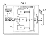
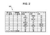
図1は、複数のインタフェースタイプをサポートする一例示的インタフェース回路基板100を含んだシステム10のブロック図を示したものである。本明細書において説明されているように、電子システムには多くのタイプのインタフェースが含まれており、また、コネクタ部分に提供されるシリアルインタフェースのタイプのみが異なる同様のシステムが含まれている。例えば制御モジュールは、複数のコネクタをサポートするだけの十分なサイズを有していないため、PROFIBUS、CANBUSおよびH1 FFのための個別モデルなどの特定のインタフェーススタイル毎に異なるモジュールタイプを強制している。PROFIBUS、CANBUSおよびH1 FFにはすべて同じコネクタスタイルが使用されている。例えばコネクタスタイルは、それらに限定されないが、DB9、RJ、DINおよび端子板であってもよい。本明細書においては、説明用としてDB9スタイルコネクタが説明されている。図2に示されているように、インタフェーススタイルPROFIBUS、CANBUSおよびH1 FFには、図2に示されているようにピンアウトおよび雌雄(雄プラグまたは雌ソケット)が異なる同じコネクタスタイルが使用されている。例示的実施形態では、本明細書において説明されているシステムは、回路基板上に設置される部品がインタフェースタイプ間で変化し、かつ、ボード当たりのコストがより安価な裸回路基板のための高体積の使用を許容するよう、共通回路基板ベースレイアウトを実施している。
FIG. 1 shows a block diagram of a
PROFIBUS、CANBUSおよびH1 FFは、回路基板100上に共存させることができ、また、回路基板100上に製造することができる3つのインタフェースタイプとして説明されているが、他の例示的実施形態では他のタイプのインタフェースが企図されていることは理解されよう。したがってPROFIBUS、CANBUSおよびH1 FFは、単に実例による説明を目的としたものにすぎない。
PROFIBUS, CANBUS, and H1 FF are described as three interface types that can co-exist on the
例示的回路基板100は、いくつかのセクション105、110、115、120を含むことができ、これらのセクションはすべて回路基板上に共存させることができ、また、複数のインタフェースタイプ(例えばPROFIBUS、CANBUSおよびH1 FF)のうちの1つとして機能させるために製造時に有利に構成することができる。第1のトランシーバセクション105はPROFIBUSのために構成することができ、また、H1 FFトランシーバは、任意選択のRS485半二重トランシーバを含むことができ、このRS485半二重トランシーバの出力も終端セクション110に結合される。回路基板100は、さらに、同じく終端セクション110に接続されるCANBUSインタフェースおよびトランシーバのために構成された第2のトランシーバセクション115を含むことができる。第1および第2のトランシーバセクション105、115および終端回路は、次に、ジャンパ(例えばゼロオーム抵抗器)の行列セクション120を介してDB9コネクタのための接続セクション125にさらに結合される。図2の表200に示されており、また、本明細書においてさらに説明されているように、DB9コネクタの雌雄のピンアウトおよび選択は、回路基板100上に設定すべきインタフェースのタイプが決定される製造時に決定し、かつ、設定することができる。DB9コネクタは、次に、システム10のフィールドバス130に結合することができる。複数のインタフェースタイプの各々はDB9コネクタへの独自の信号マッピングを有していることは当業者には理解されよう。例示的実施形態では、行列セクション120は、独自の信号マッピングの各々をサポートするように構成される。
The
例示的実施形態では、回路基板100のインタフェースの制御は、システム10の論理および/またはFPGAコントローラセクション135からの一組の共有信号によって実施され、これらの信号は、ボード上に設置される、選択されるインタフェースに基づいて異なる機能に割り当てられる。例えば製造によってコントローラセクションにロードされるファームウェアは、インタフェースタイプのために実施される信号およびプロトコルを決定することができる。例示的実施形態では、コントローラセクション135はイーサネット(商標)に基づくことができる。コントローラセクション135は、さらに、システム10内の他のインタフェース/電子工学140に結合することができる。
In the exemplary embodiment, the control of the
本明細書において説明されているように、製造者は、所望のインタフェースのために設置すべき特定の部品を部品表に基づいて選択し、集積回路、抵抗器および他のコンポーネントを含む特定の部品がインタフェースタイプに基づいて追加され、あるいは除去される。 As described herein, the manufacturer selects specific parts to be installed for the desired interface based on the bill of materials and includes specific parts including integrated circuits, resistors and other components. Are added or removed based on the interface type.
したがって例示的回路基板100は、より大きいシステム10内にフィールドバス130インタフェースを提供し、かつ、複数のタイプのプロトコルおよび接続のうちの1つをサポートしており、インタフェースの回路基板100上に設置されているコンポーネントを選択することにより、プロトコルのタイプ(例えばPROFIBUS、CANBUSおよびH1 FF)がインタフェース製造時に選択される。接続は、共通共有コネクタスタイル(例えばDB9)を介して実施され、製造するコンポーネントの選択がさらに実施されて、特定のコネクタピンがインタフェース機能に割り当てられる。インタフェースの動作は、回路基板のシステム10の残りの部分を接続することによって実施され、これらの接続は、設置されるインタフェースに基づいて異なる機能を有している。フィールドバスインタフェース回路基板100は、さらに、この回路基板およびインタフェースを含んだモジュールを、追加終端を必要とすることなく、インタフェースバスに沿った任意の場所に設置することができるよう、内部で制御される終端ネットワーク(例えば終端セクション110)をサポートしている。
Thus, the
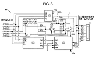
図3は、PROFIBUS、CANBUSおよびH1 FFならびに対応する個々の部品が製造時に選択される一例示的回路300の回路図を示したものである。回路300には、本明細書において説明されている3つのトランシーバセクションUT1、UT2、UT3が含まれている。このレイアウトには、さらに、抵抗器RT1、RT2、RT3、RT4、RT5、RT6、RT7、継電器K1およびトランジスタQTを含んだ終端セクションTが含まれている。回路300には、さらに、FPGA入力線OPTION1、OPTION2、OPTION3、OPTION4、OPTION5、OPTION6が含まれている。このレイアウトには、さらに、インタフェースへのジャンパ行列として、外部コネクタC(例えば本明細書において説明されているDB9コネクタ)を備えた出力線RJ1、RJ2、RJ3、RJ4、RJ5、RJ6(例えば0オームジャンパ)が含まれている。
FIG. 3 shows a schematic diagram of an
本明細書において説明されているように、回路300には、いくつかのインタフェースのうちの1つ、例えばそれには限定されないが、これから説明するPROFIBUS、CANBUSおよびH1 FFのうちの1つになるように製造時に構成することができるコンポーネントセクションが含まれている。
As described herein,
PROFIBUSの場合、UT1、RT1、RT2、RT3、RT4、RT6、RT7、QT、K1が回路300上に設置される。さらに、雌DB9コネクタがコネクタセクションCに設置される。ジャンパRJ1、RJ3は、UTIアクティブハイ出力(CANH)が雌DB9のコネクタピン3に接続されるように接続される(図2参照)。ジャンパRJ2、RJ4は、アクティブロー出力(信号CANL)が雌DB9コネクタのコネクタピン8に接続されるように接続される(図2参照)。ジャンパRJ5、RJ6は、UT1の共通信号がDB9コネクタのピン5に接続されるように接続される(図2参照)。PROFIBUSの場合は、UT2、UT3およびRT5は設置されない。コントローラのための信号は、レシーバアクティブRAのためのOPTION1、トランスミットイネーブルTEのためのOPTION2、レシーババックRBのためのOPTION3、トランスミットアウトTAのためのOPTION4、終端制御のためのOPTION5、および終端セクションTからのトランジスタQTおよび継電器K1を介した継電器フィードバックのためのOPTION6である。UT1入力には、さらに、フローティング供給電圧VBSおよび制御電圧VCOが含まれている。
In the case of PROFIBUS, UT1, RT1, RT2, RT3, RT4, RT6, RT7, QT, and K1 are installed on the
H1 FFの場合、UT1、RT1、RT2、RT3、RT4、RT6、RT7、QT、K1が回路300上に設置される。さらに、コネクタセクションCには雄DB9コネクタが接続される。ジャンパRJ1、RJ3は、UTIアクティブハイ出力(CANH)がDB9雄コネクタのコネクタピン6に接続されるように接続される(図2参照)。ジャンパRJ2、RJ4は、アクティブロー出力(信号CANL)が雄DB9コネクタのコネクタピン7に接続されるように接続される(図2参照)。H1 FFの場合は、UT2、UT3およびRT5は設置されない。コントローラのための信号は、レシーバアクティブのためのOPTION1、トランスミットイネーブルのためのOPTION2、レシーババックのためのOPTION3、トランスミットアウトのためのOPTION4、終端制御のためのOPTION5、および終端セクションTからのトランジスタQTおよび継電器K1を介した継電器フィードバックのためのOPTION6である。UT1入力には、さらに、フローティング供給電圧VBSおよび制御電圧VCOが含まれている。
In the case of H1 FF, UT1, RT1, RT2, RT3, RT4, RT6, RT7, QT, and K1 are installed on the
CANBUSの場合、UT2、UT3、RT2、RT5、RT6、RT7、Q1、K1が回路300上に設置される。さらに、接続セクションCには雄DB9コネクタが接続される。ジャンパRJ1、RJ3は、UT3アクティブハイ出力(CANH)がDB9雄コネクタのコネクタピン7に接続されるように接続される(図2参照)。ジャンパRJ2、RJ4は、アクティブロー出力(信号CANL)が雄DB9コネクタのコネクタピン5および6に接続されるように接続される(図2参照)。CANBUSの場合は、UT1、RT1、RT3、RT5は設置されない。コントローラのための信号は、選択のためのOPTION1、クロックのためのOPTION2、CANへのデータのためのOPTION3、CANからのデータのためのOPTION4、CAN割込みのためのOPTION5、および終端セクションTからのトランジスタQTおよび継電器K1を介した継電器フィードバックのためのOPTION6である。
In the case of CANBUS, UT2, UT3, RT2, RT5, RT6, RT7, Q1, and K1 are installed on the
インタフェースの制御は、同様にインタフェースタイプに応じて変化する。本明細書において説明されているように、PROFIBUSおよびH1 FFの場合、トランシーバセクションUT1は、図3に示されているようにRS485トランシーバであってもよい。したがってPROFIBUSおよびH1 FFには、いずれも、制御論理内の、31.25Kbpsで動作させることができるUARTによって制御される半二重直列伝送が利用されている。PROFIBUSおよびH1 FFの主な電気的な相違は、コネクタの雌雄および接続にある。CANBUSは、インタフェースドライバに対するUT2を介した同期周辺インタフェース(SPI)ポートを実現し、選択(UT2上のNCS入力)、クロック(UT2上のSCK入力)、およびUT2上のデータフローSIおよびSOのために任意選択ピンの再割当てを実施する。さらに、UT2は、TXD信号およびRXD信号をそれぞれUT3上のTXD信号、RXD信号にマップする。信号I/O1は終端セクションTに出力される。UT3入力には、さらに、基準タイマRsおよび基準電圧Vref、フローティング供給電圧VBSおよび制御電圧VCOが含まれている。 The control of the interface also varies depending on the interface type. As described herein, for PROFIBUS and H1 FF, transceiver section UT1 may be an RS485 transceiver as shown in FIG. Therefore, both PROFIBUS and H1 FF utilize half-duplex serial transmission controlled by UART that can operate at 31.25 Kbps in the control logic. The main electrical differences between PROFIBUS and H1 FF are the male and female connectors and connections. CANBUS implements a synchronous peripheral interface (SPI) port via UT2 to the interface driver for selection (NCS input on UT2), clock (SCK input on UT2), and data flow SI and SO on UT2. Reassign optional pins. Furthermore, UT2 maps the TXD signal and RXD signal to the TXD signal and RXD signal on UT3, respectively. The signal I / O1 is output to the termination section T. The UT3 input further includes a reference timer Rs and a reference voltage Vref, a floating supply voltage VBS and a control voltage VCO .
本明細書において説明されているように、バスの終端は回路300内にも提供される。終端のためには、これから説明する伝送線路終端のために使用される終端抵抗器との回路の接続および開放が必要である。回路300を含んだモジュールがバスに沿って他のモジュールと共にフィールドバスに取り付けられると、バスの末端には終端が必要であり、また、バスの中間に接続されているモジュールを開放しなければならない。継電器K1を使用して、抵抗器RT1、RT2およびRT3の終端アレイを接続することができ、それにより終端を例えばプルアップし、並列にし、また、プルダウンすることができる。
As described herein, bus termination is also provided in
継電器が終端をバスから開放しているフィードバックとして、抵抗器RT6およびRT7は、継電器K1が終端を接続しているとOPTION6信号をローに引っ張ることができ、また、K1が終端を開放しているとハイに引っ張ることができる。継電器K1の制御は、OPTION5(同じトランシーバUT1を使用しているPROFIBUSまたはH1 FF)またはCANインタフェースUT2からのI/O1信号のいずれかによって駆動されるトランジスタQTを介して実施される。したがって継電器K1は、より高価な継電器を必要とする個別のフィードバックスイッチを備えた3極継電器と比較すると2極双投(DPDT)継電器であってもよく、それにより回路300のコストが低減される。
As feedback that the relay opens the termination from the bus, resistors RT6 and RT7 can pull the OPTION6 signal low when the relay K1 is connected to the termination, and K1 is opening the termination. And can be pulled high. The control of relay K1 is implemented via transistor QT driven by either OPTION 5 (PROFIBUS or H1 FF using the same transceiver UT1) or the I / O1 signal from CAN interface UT2. Thus, relay K1 may be a double pole double throw (DPDT) relay compared to a three pole relay with a separate feedback switch that requires a more expensive relay, thereby reducing the cost of
当業者には理解されるように、適切な情報の流れを生成し、また、構成される(例えばFPGAコントローラセクション135に)ハードウェアと整合させるために製造時にロードされる、異なるコード分岐または異なるプログラムを備えた1つのプログラムの一部として構成可能な線を別様に駆動するための命令などの本発明の態様は、選択されるインタフェースに応じた信号の制御および機能を提供するためのシステム、方法またはコンピュータプログラム製品として具体化することができる。したがって本発明の態様は、そのすべてがハードウェア実施形態の形態、そのすべてがソフトウェア実施形態の形態(ファームウェア、常駐ソフトウェア、マイクロコード、等々を含む)、またはソフトウェア態様とハードウェア態様とを組み合わせた実施形態の形態を取ることができ、これらはすべて、本明細書においては一括して「回路」、「モジュール」または「システム」と呼ぶことができる。さらに、本発明の態様は、コンピュータ可読プログラムコードがその上に具体化された1つまたは複数のコンピュータ可読媒体の中に具体化されたコンピュータプログラム製品の形態を取ることができる。 As will be appreciated by those skilled in the art, different code branches or different loads that are loaded at the time of manufacture to generate the appropriate information flow and to match the configured hardware (eg, in the FPGA controller section 135) Aspects of the present invention, such as instructions for driving differently configurable lines as part of a program with a program, provide a system for providing signal control and functions depending on the selected interface Can be embodied as a method or computer program product. Accordingly, aspects of the present invention are all in the form of hardware embodiments, all in the form of software embodiments (including firmware, resident software, microcode, etc.), or a combination of software and hardware aspects. It can take the form of an embodiment, all of which can be collectively referred to herein as a “circuit”, “module”, or “system”. Furthermore, aspects of the invention may take the form of a computer program product embodied in one or more computer readable media having computer readable program code embodied thereon.
1つまたは複数のコンピュータ可読媒体の任意の組合せを利用することができる。コンピュータ可読媒体は、コンピュータ可読信号媒体またはコンピュータ可読記憶媒体であってもよい。コンピュータ可読記憶媒体は、例えば、それらに限定されないが、電子、磁気、光、電磁、赤外線または半導体のシステム、装置またはデバイスであっても、あるいはそれらの任意の適切な組合せであってもよい。コンピュータ可読記憶媒体のより特定の例には(それらに限定されないが)、1本または複数本の配線を有する電気接続、携帯型コンピュータディスケット、ハードディスク、ランダムアクセスメモリ(RAM)、リードオンリメモリ(ROM)、消去可能プログラマブルリードオンリメモリ(EPROMまたはフラッシュメモリ)、光ファイバ、携帯型コンパクトディスクリードオンリメモリ(CD−ROM)、光記憶装置、磁気記憶装置またはそれらの任意の適切な組合せがある。本文書のコンテキストにおいては、コンピュータ可読記憶媒体は、命令実行システム、装置またはデバイスが使用し、あるいはこれらの命令実行システム、装置またはデバイスと共に使用するためのプログラムを含むか、あるいは記憶することができる任意の有形媒体であってもよい。 Any combination of one or more computer readable media may be utilized. The computer readable medium may be a computer readable signal medium or a computer readable storage medium. The computer readable storage medium may be, for example but not limited to, an electronic, magnetic, optical, electromagnetic, infrared, or semiconductor system, apparatus, or device, or any suitable combination thereof. More specific examples of computer readable storage media include (but are not limited to) electrical connections having one or more wires, portable computer diskettes, hard disks, random access memory (RAM), read only memory (ROM) ), Erasable programmable read only memory (EPROM or flash memory), optical fiber, portable compact disk read only memory (CD-ROM), optical storage device, magnetic storage device or any suitable combination thereof. In the context of this document, a computer-readable storage medium may contain or store a program for use by or with an instruction execution system, apparatus or device. Any tangible medium may be used.
コンピュータ可読信号媒体は、例えばベースバンド中に、あるいは搬送波の一部としてコンピュータ可読プログラムコードがその中に具体化された伝搬データ信号を含むことができる。このような伝搬信号は、それらに限定されないが、電気−磁気、光またはそれらの任意の適切な組合せを含む任意の様々な形態を取ることができる。コンピュータ可読信号媒体は、コンピュータ可読記憶媒体ではなく、また、命令実行システム、装置またはデバイスが使用し、あるいはこれらの命令実行システム、装置またはデバイスと共に使用するためのプログラムを通信、伝搬または輸送することができる任意のコンピュータ可読媒体であってもよい。 A computer readable signal medium may include a propagated data signal with computer readable program code embodied therein, for example, in baseband or as part of a carrier wave. Such propagated signals can take any of a variety of forms including, but not limited to, electro-magnetic, optical, or any suitable combination thereof. A computer readable signal medium is not a computer readable storage medium, and also communicates, propagates or transports a program for use by or with an instruction execution system, apparatus or device. Any computer readable medium capable of
コンピュータ可読媒体上に具体化されたプログラムコードは、それらに限定されないが、無線、ワイヤ線、光ファイバケーブル、RF、等々、またはそれらの任意の適切な組合せを含む任意の適切な媒体を使用して伝送することができる。 Program code embodied on a computer readable medium may be any suitable medium including, but not limited to, wireless, wireline, fiber optic cable, RF, etc., or any suitable combination thereof. Can be transmitted.
本発明の態様のための動作を実施するためのコンピュータプログラムコードは、Java(商標)、Smalltalk、C++、等々などのオブジェクト指向プログラミング言語、および「C」プログラミング言語または類似のプログラミング言語などの従来の手続き形プログラミング言語を含む1つまたは複数のプログラミング言語の任意の組合せで書くことができる。プログラムコードは、そのすべてを使用者のコンピュータ上で実行することも、独立ソフトウェアパッケージとして一部を使用者のコンピュータ上で実行することも、一部を使用者のコンピュータ上で、また、一部を遠隔コンピュータ上で実施することも、あるいはそのすべてを遠隔コンピュータ上またはサーバ上で実施することも可能である。後者のシナリオの場合、遠隔コンピュータは、ローカルエリアネットワーク(LAN)または広域ネットワーク(WAN)を含む任意のタイプのネットワークを介して使用者のコンピュータに接続することができ、あるいは外部コンピュータに接続することができる(例えばインターネットサービスプロバイダを使用したインターネットを介して)。 Computer program code for performing the operations for aspects of the present invention is conventional object-oriented programming languages such as Java ™, Smalltalk, C ++, etc., and conventional programming languages such as the “C” programming language or similar programming languages. It can be written in any combination of one or more programming languages, including procedural programming languages. All of the program code can be executed on the user's computer, or part of the program code can be executed on the user's computer as an independent software package, or partly on the user's computer. Can be implemented on a remote computer, or all of them can be implemented on a remote computer or on a server. In the latter scenario, the remote computer can be connected to the user's computer via any type of network, including a local area network (LAN) or a wide area network (WAN), or connected to an external computer. (E.g. via the internet using an internet service provider).
技術的な効果には、複数のインタフェースタイプの基本セクションおよびコンポーネントを収納するための共通回路基板の実施態様によるコストの低減が含まれる。製造コストおよびハードウェア開発コストの低減は、共有回路基板レイアウト上での機能の組合せによるものである。共通回路基板を使用することにより、量が多くなるほど、大量生産によって総コストが低減される。 Technical effects include cost reductions due to the implementation of a common circuit board to accommodate basic sections and components of multiple interface types. The reduction in manufacturing cost and hardware development cost is due to a combination of functions on the shared circuit board layout. By using a common circuit board, the higher the volume, the lower the total cost due to mass production.
本明細書において説明されている例示的実施形態には、さらに、ファームウェアを介して制御信号を変更することができるプログラム可能バス終端が含まれている。DPDT継電器(この継電器は3PDT継電器よりコストが安価である)のみが使用されているが、本明細書において説明されている例示的実施形態には、さらに、継電器動作の診断検証が含まれている。複数のプロトコルをハードウェアでサポートするためには、さらに、終端回路の変更が必要である。継電器スイッチおよび終端抵抗器ネットワークを提供することにより、部品表を変更する(抵抗器の除去および/または挿入の両方を変更し、かつ、抵抗器の値を変更する)ことによって異なるプロトコルを提供することができる。また、この継電器スイッチングにより、端点では終端を接続し、また、中間ケーブル接続では終端を開放しなければならないフィールドバスに沿ってモジュールを配置することができる。過去の実施態様では、終端を選択するためのジャンパまたはスイッチを使用者が設定する必要があったが、本明細書において説明されている例示的実施形態によれば、モジュール内部設定(しばしばイーサネット(商標)または制御パネル設定などの他のインタフェースによって供給される)による制御の下での継電器が実現される。 The exemplary embodiments described herein further include programmable bus terminations that can change control signals through firmware. Although only DPDT relays (which are less expensive than 3PDT relays) are used, the exemplary embodiments described herein further include diagnostic verification of relay operation. . In order to support a plurality of protocols in hardware, it is further necessary to change the termination circuit. Provide different protocols by changing the bill of materials (changing both resistor removal and / or insertion, and changing resistor values) by providing relay switches and termination resistor networks be able to. This relay switching also allows modules to be placed along a fieldbus that must be terminated at the endpoint and open at the intermediate cable connection. In past implementations, the user had to set jumpers or switches to select terminations, but according to the exemplary embodiments described herein, module internal settings (often Ethernet ( A relay under control (provided by trademark or other interface such as control panel settings) is realized.
以上、本発明について、ごく限られた数の実施形態に関連して詳細に説明したが、本発明は、開示されているこのような実施形態に限定されないことは容易に理解されよう。そうではなく、本発明は、説明されていない任意の数の変形形態、変更、置換または等価構造を組み込むべく修正することができるが、それらは本発明の精神および範囲と同一基準である。また、本発明の様々な実施形態が説明されているが、本発明の態様は、説明されている複数の実施形態のうちの一部のみを含むことも可能であることを理解されたい。したがって本発明は、以上の説明によって制限されるものと見なしてはならず、本発明は、特許請求の範囲によってのみ制限される。 Although the present invention has been described in detail in connection with a very limited number of embodiments, it will be readily understood that the invention is not limited to such disclosed embodiments. Rather, the invention can be modified to incorporate any number of variations, alterations, substitutions or equivalent structures not described, which are consistent with the spirit and scope of the invention. Also, while various embodiments of the invention have been described, it should be understood that aspects of the invention may include only some of the described embodiments. Accordingly, the invention is not to be seen as limited by the foregoing description, but is limited only by the scope of the claims.
10 システム
100 インタフェース回路基板
105、115、UT1、UT2、UT3 トランシーバセクション
110、T 終端セクション
120 行列セクション
125 接続セクション
130 フィールドバス
135 コントローラセクション
140 インタフェース/電子工学
300 回路
RT1、RT2、RT3、RT4、RT5、RT6、RT7 抵抗器
K1 継電器
QT トランジスタ
OPTION1、OPTION2、OPTION3、OPTION4、OPTION5、OPTION6 入力線
RJ1、RJ2、RJ3、RJ4、RJ5、RJ6 出力線
C 外部コネクタ
VBS フローティング供給電圧
VCO 制御電圧
CANL 信号
CANH 出力
10
Claims (9)
共有回路基板(100)ベースと、
前記回路基板(100)ベースの上に配置されたトランシーバセクション(115)であって、複数のトランシーバコンポーネントタイプを受け取る回路トランシーバサイトを有するトランシーバセクション(115)と、
前記回路基板(100)ベースの上に配置された終端セクション(110)であって、複数の終端コンポーネントタイプを受け取る回路終端サイトを有する終端セクション(110)と、
前記トランシーバおよび終端セクション(115、110)に動作結合された接続セクション(125)と、
前記トランシーバおよび前記終端セクション(110)と、前記接続セクション(125)との間に配置された手動設定変更可能なジャンパのセクションと、
を備え、
前記手動設定変更可能なジャンパは、特定の接続タイプの信号マッピングをサポートするように、製造時に設定され、
前記トランシーバセクション(115)、前記終端セクション(110)および前記手動設定変更可能なジャンパのセクションは、前記複数のトランシーバコンポーネントタイプおよび前記複数の終端コンポーネントタイプに基づく複数のインターフェイスタイプをサポートするための電気接続サイトを含み、
第1の組のトランシーバコンポーネントおよび終端コンポーネントが、第1のインターフェイスタイプをサポートするために、前記トランシーバセクションおよび前記終端セクションに搭載され、
第2の組のトランシーバコンポーネントおよび終端コンポーネントが、第2のインターフェイスタイプをサポートするために、前記トランシーバセクションおよび前記終端セクションに搭載され、
前記第2の組のトランシーバコンポーネントおよび終端コンポーネントは、前記第1の組のトランシーバコンポーネントおよび終端コンポーネントと異なる、
インタフェース回路基板装置。 An interface circuit board device,
A shared circuit board (100) base;
A transceiver section (115) disposed on the circuit board (100) base, the transceiver section (115) having a circuit transceiver site for receiving a plurality of transceiver component types;
A termination section (110) disposed on the circuit board (100) base, the termination section (110) having a circuit termination site for receiving a plurality of termination component types;
A connection section (125) operatively coupled to the transceiver and termination section (115, 110);
A manually configurable jumper section disposed between the transceiver and the termination section (110) and the connection section (125);
With
The manually configurable jumper is set at the time of manufacture to support signal mapping for a particular connection type;
The transceiver section (115), the termination section (110), and the manually configurable jumper section are electrical to support the plurality of transceiver component types and a plurality of interface types based on the plurality of termination component types Including connected sites,
A first set of transceiver components and termination components are mounted on the transceiver section and the termination section to support a first interface type;
A second set of transceiver components and termination components are mounted on the transceiver section and the termination section to support a second interface type;
The second set of transceiver and termination components is different from the first set of transceiver and termination components;
Interface circuit board device.
前記複数のインタフェースタイプの各々が、前記コネクタへの独自の信号マッピングを有する、
請求項3に記載の装置。 The manually configurable jumper section includes a jumper connection site supporting the plurality of interface types;
Each of the plurality of interface types has its own signal mapping to the connector;
The apparatus of claim 3.
前記コントローラ信号入力の各々が前記複数のインタフェースタイプのうちの選択されたインタフェースタイプに基づく独自の構成を有する、
請求項1から4のいずれかに記載の装置。 The transceiver section (115) and the termination section (110) have electrical connections for receiving a plurality of controller signal inputs;
Each of the controller signal inputs has a unique configuration based on a selected interface type of the plurality of interface types;
Apparatus according to any one of claims 1 to 4.
It said transceiver section (115) has an electrical connection that supports one or more transceivers types that are configured to support the plurality of interfaces type device according to any one of claims 1 to 8.
Applications Claiming Priority (2)
| Application Number | Priority Date | Filing Date | Title |
|---|---|---|---|
| US13/012,376 | 2011-01-24 | ||
| US13/012,376 US8625295B2 (en) | 2011-01-24 | 2011-01-24 | Fieldbus interface circuit board supporting multiple interface types and terminations |
Publications (3)
| Publication Number | Publication Date |
|---|---|
| JP2012155719A JP2012155719A (en) | 2012-08-16 |
| JP2012155719A5 JP2012155719A5 (en) | 2015-02-26 |
| JP5960993B2 true JP5960993B2 (en) | 2016-08-02 |
Family
ID=45562708
Family Applications (1)
| Application Number | Title | Priority Date | Filing Date |
|---|---|---|---|
| JP2012009513A Active JP5960993B2 (en) | 2011-01-24 | 2012-01-20 | Fieldbus interface circuit board supporting multiple interface types and terminations |
Country Status (4)
| Country | Link |
|---|---|
| US (1) | US8625295B2 (en) |
| EP (1) | EP2479678B1 (en) |
| JP (1) | JP5960993B2 (en) |
| CN (1) | CN102693204B (en) |
Families Citing this family (10)
| Publication number | Priority date | Publication date | Assignee | Title |
|---|---|---|---|---|
| JP2014115756A (en) * | 2012-12-07 | 2014-06-26 | Tamagawa Seiki Co Ltd | Communication method selection circuit, and method of the same |
| CN106165349B (en) * | 2014-01-03 | 2020-06-19 | 凤凰通讯发展及制造股份有限公司 | Fieldbus network with two-wire loop |
| US9840220B2 (en) | 2015-04-27 | 2017-12-12 | L & B Manufacturing, Inc. | Wireless airbag control system |
| FR3038807B1 (en) | 2015-07-09 | 2017-07-21 | Continental Automotive France | TRANSCEIVER DEVICE CAPABLE OF CONNECTING TO A CAN OR FLEXRAY BUS COMMUNICATION NETWORK |
| BE1026569B1 (en) | 2018-08-27 | 2020-03-23 | Phoenix Contact Gmbh & Co | Control and data transmission system to support various communication protocols and an adapter module |
| CN108965118B (en) * | 2018-08-31 | 2021-04-16 | 杭州和利时自动化有限公司 | DP-to-FF communication gateway and DP-to-FF method |
| DE102018121885A1 (en) * | 2018-09-07 | 2020-03-12 | Phoenix Contact Gmbh & Co. Kg | Electronic device for use in an automation system and an automation system |
| EP4099641A1 (en) * | 2021-06-03 | 2022-12-07 | Nxp B.V. | Transceiver device |
| CN113848788B (en) * | 2021-09-27 | 2022-12-02 | 厦门四信通信科技有限公司 | Expansion circuit and system |
| CN114281743A (en) * | 2021-11-29 | 2022-04-05 | 浪潮(山东)计算机科技有限公司 | Device and method for converting PCIE (peripheral component interface express) to RS232 interface and TTL (transistor-transistor logic) interface and storage medium |
Family Cites Families (15)
| Publication number | Priority date | Publication date | Assignee | Title |
|---|---|---|---|---|
| US4124889A (en) * | 1975-12-24 | 1978-11-07 | Computer Automation, Inc. | Distributed input/output controller system |
| US5832244A (en) * | 1996-02-20 | 1998-11-03 | Iomega Corporation | Multiple interface input/output port for a peripheral device |
| US6088754A (en) * | 1997-12-31 | 2000-07-11 | Cisco Technology, Inc. | Generic serial interface with automatic reconfigurability |
| US6334160B1 (en) * | 1999-01-28 | 2001-12-25 | Hewlett-Packard Co. | Apparatus and method for providing multiple protocols through a common connector in a device |
| US6740821B1 (en) | 2002-03-01 | 2004-05-25 | Micron Technology, Inc. | Selectively configurable circuit board |
| US7035773B2 (en) * | 2002-03-06 | 2006-04-25 | Fisher-Rosemount Systems, Inc. | Appendable system and devices for data acquisition, analysis and control |
| US6839790B2 (en) | 2002-06-21 | 2005-01-04 | Smar Research Corporation | Plug and play reconfigurable USB interface for industrial fieldbus network access |
| US7246194B2 (en) * | 2003-01-30 | 2007-07-17 | Rosemount, Inc. | Interface module for use with a fieldbus device network and with internet and non-internet based process control networks |
| US7245501B2 (en) | 2003-09-09 | 2007-07-17 | Hewlett-Packard Development Company, L.P. | Configurable circuit board and fabrication method |
| EP1805627B1 (en) | 2004-10-15 | 2011-02-16 | Sony Computer Entertainment Inc. | Methods and apparatus for supporting multiple configurations in a multi-processor system |
| CN2811962Y (en) * | 2005-07-18 | 2006-08-30 | 北京金自天正智能控制股份有限公司 | Synchronous motor state detector based on Profibus-DP field bus |
| CN2884280Y (en) * | 2005-11-09 | 2007-03-28 | 沈阳新松机器人自动化股份有限公司 | On-line bus position controller |
| US7715433B2 (en) * | 2006-07-14 | 2010-05-11 | Boren Gary W | Universal controller and signal monitor |
| US20080065805A1 (en) * | 2006-09-11 | 2008-03-13 | Cameo Communications, Inc. | PCI-Express multimode expansion card and communication device having the same |
| US20090282437A1 (en) * | 2008-05-09 | 2009-11-12 | Tap.Tv | System and Method for Controlling Media at a Plurality of Output Devices |
-
2011
- 2011-01-24 US US13/012,376 patent/US8625295B2/en active Active
-
2012
- 2012-01-10 EP EP12150538.2A patent/EP2479678B1/en active Active
- 2012-01-20 JP JP2012009513A patent/JP5960993B2/en active Active
- 2012-01-29 CN CN201210026067.3A patent/CN102693204B/en active Active
Also Published As
| Publication number | Publication date |
|---|---|
| CN102693204B (en) | 2016-06-15 |
| US8625295B2 (en) | 2014-01-07 |
| JP2012155719A (en) | 2012-08-16 |
| US20120188731A1 (en) | 2012-07-26 |
| EP2479678B1 (en) | 2016-10-12 |
| CN102693204A (en) | 2012-09-26 |
| EP2479678A2 (en) | 2012-07-25 |
| EP2479678A3 (en) | 2013-09-11 |
Similar Documents
| Publication | Publication Date | Title |
|---|---|---|
| JP5960993B2 (en) | Fieldbus interface circuit board supporting multiple interface types and terminations | |
| JP5081987B2 (en) | Asymmetric universal serial bus communication | |
| CN101539900B (en) | Device for solving conflict generated between two I<2>C slave devices with same addressing address | |
| CN104054064B (en) | Flexible port configuration based on interface coupling | |
| CN107391419B (en) | Support general sequence busbar concentrator of many host computers and automobile-used host computer | |
| CN108302742B (en) | Controller of air conditioning unit and air conditioner | |
| CN204904151U (en) | Built -in switching card | |
| CN204883525U (en) | External switching card | |
| US10271113B2 (en) | Chassis switch using distributed backplane to interconnect line cards | |
| CN105703935B (en) | Tool automatically switches the server system of shared network function | |
| TW202005485A (en) | Switch board for expanding peripheral component interconnect express compatibility | |
| CN109561032B (en) | Switch module reaches switch including it | |
| US8131903B2 (en) | Multi-channel memory connection system and method | |
| CN110323644B (en) | Adapter and signal transmission method thereof | |
| US20120036294A1 (en) | Computer integrated display integrated display and control method of the same | |
| US8583849B2 (en) | Signal switch connector set applied to motherboard of computer system | |
| CN210270889U (en) | Intelligent analysis expansion equipment and server | |
| CN211124034U (en) | Multi-path acquisition card and server with same | |
| CN103631749B (en) | Enlargement module | |
| CN107515833A (en) | Input-output card and storage device for storage device | |
| KR100877627B1 (en) | The hub combining voice and data | |
| US20070225829A1 (en) | Information processing apparatus | |
| JP2006174352A (en) | Remote i/o module communication equipment | |
| JP5233519B2 (en) | Electronics | |
| CN210123977U (en) | Relay cable and augmented reality system |
Legal Events
| Date | Code | Title | Description |
|---|---|---|---|
| A521 | Request for written amendment filed |
Free format text: JAPANESE INTERMEDIATE CODE: A523 Effective date: 20150113 |
|
| A621 | Written request for application examination |
Free format text: JAPANESE INTERMEDIATE CODE: A621 Effective date: 20150113 |
|
| A977 | Report on retrieval |
Free format text: JAPANESE INTERMEDIATE CODE: A971007 Effective date: 20151111 |
|
| A131 | Notification of reasons for refusal |
Free format text: JAPANESE INTERMEDIATE CODE: A131 Effective date: 20151117 |
|
| A521 | Request for written amendment filed |
Free format text: JAPANESE INTERMEDIATE CODE: A523 Effective date: 20160212 |
|
| TRDD | Decision of grant or rejection written | ||
| A01 | Written decision to grant a patent or to grant a registration (utility model) |
Free format text: JAPANESE INTERMEDIATE CODE: A01 Effective date: 20160531 |
|
| A61 | First payment of annual fees (during grant procedure) |
Free format text: JAPANESE INTERMEDIATE CODE: A61 Effective date: 20160624 |
|
| R150 | Certificate of patent or registration of utility model |
Ref document number: 5960993 Country of ref document: JP Free format text: JAPANESE INTERMEDIATE CODE: R150 |
|
| R250 | Receipt of annual fees |
Free format text: JAPANESE INTERMEDIATE CODE: R250 |
|
| R250 | Receipt of annual fees |
Free format text: JAPANESE INTERMEDIATE CODE: R250 |
|
| R250 | Receipt of annual fees |
Free format text: JAPANESE INTERMEDIATE CODE: R250 |
|
| R250 | Receipt of annual fees |
Free format text: JAPANESE INTERMEDIATE CODE: R250 |
|
| R250 | Receipt of annual fees |
Free format text: JAPANESE INTERMEDIATE CODE: R250 |
|
| S111 | Request for change of ownership or part of ownership |
Free format text: JAPANESE INTERMEDIATE CODE: R313113 |
|
| R350 | Written notification of registration of transfer |
Free format text: JAPANESE INTERMEDIATE CODE: R350 |