JP5960461B2 - Brake device - Google Patents
Brake device Download PDFInfo
- Publication number
- JP5960461B2 JP5960461B2 JP2012063988A JP2012063988A JP5960461B2 JP 5960461 B2 JP5960461 B2 JP 5960461B2 JP 2012063988 A JP2012063988 A JP 2012063988A JP 2012063988 A JP2012063988 A JP 2012063988A JP 5960461 B2 JP5960461 B2 JP 5960461B2
- Authority
- JP
- Japan
- Prior art keywords
- braking force
- brake
- hydraulic
- electric
- hydraulic fluid
- Prior art date
- Legal status (The legal status is an assumption and is not a legal conclusion. Google has not performed a legal analysis and makes no representation as to the accuracy of the status listed.)
- Expired - Fee Related
Links
Images


Classifications
-
- B—PERFORMING OPERATIONS; TRANSPORTING
- B60—VEHICLES IN GENERAL
- B60T—VEHICLE BRAKE CONTROL SYSTEMS OR PARTS THEREOF; BRAKE CONTROL SYSTEMS OR PARTS THEREOF, IN GENERAL; ARRANGEMENT OF BRAKING ELEMENTS ON VEHICLES IN GENERAL; PORTABLE DEVICES FOR PREVENTING UNWANTED MOVEMENT OF VEHICLES; VEHICLE MODIFICATIONS TO FACILITATE COOLING OF BRAKES
- B60T13/00—Transmitting braking action from initiating means to ultimate brake actuator with power assistance or drive; Brake systems incorporating such transmitting means, e.g. air-pressure brake systems
- B60T13/74—Transmitting braking action from initiating means to ultimate brake actuator with power assistance or drive; Brake systems incorporating such transmitting means, e.g. air-pressure brake systems with electrical assistance or drive
- B60T13/745—Transmitting braking action from initiating means to ultimate brake actuator with power assistance or drive; Brake systems incorporating such transmitting means, e.g. air-pressure brake systems with electrical assistance or drive acting on a hydraulic system, e.g. a master cylinder
-
- B—PERFORMING OPERATIONS; TRANSPORTING
- B60—VEHICLES IN GENERAL
- B60T—VEHICLE BRAKE CONTROL SYSTEMS OR PARTS THEREOF; BRAKE CONTROL SYSTEMS OR PARTS THEREOF, IN GENERAL; ARRANGEMENT OF BRAKING ELEMENTS ON VEHICLES IN GENERAL; PORTABLE DEVICES FOR PREVENTING UNWANTED MOVEMENT OF VEHICLES; VEHICLE MODIFICATIONS TO FACILITATE COOLING OF BRAKES
- B60T13/00—Transmitting braking action from initiating means to ultimate brake actuator with power assistance or drive; Brake systems incorporating such transmitting means, e.g. air-pressure brake systems
- B60T13/10—Transmitting braking action from initiating means to ultimate brake actuator with power assistance or drive; Brake systems incorporating such transmitting means, e.g. air-pressure brake systems with fluid assistance, drive, or release
- B60T13/58—Combined or convertible systems
- B60T13/588—Combined or convertible systems both fluid and mechanical assistance or drive
-
- B—PERFORMING OPERATIONS; TRANSPORTING
- B60—VEHICLES IN GENERAL
- B60T—VEHICLE BRAKE CONTROL SYSTEMS OR PARTS THEREOF; BRAKE CONTROL SYSTEMS OR PARTS THEREOF, IN GENERAL; ARRANGEMENT OF BRAKING ELEMENTS ON VEHICLES IN GENERAL; PORTABLE DEVICES FOR PREVENTING UNWANTED MOVEMENT OF VEHICLES; VEHICLE MODIFICATIONS TO FACILITATE COOLING OF BRAKES
- B60T13/00—Transmitting braking action from initiating means to ultimate brake actuator with power assistance or drive; Brake systems incorporating such transmitting means, e.g. air-pressure brake systems
- B60T13/74—Transmitting braking action from initiating means to ultimate brake actuator with power assistance or drive; Brake systems incorporating such transmitting means, e.g. air-pressure brake systems with electrical assistance or drive
- B60T13/741—Transmitting braking action from initiating means to ultimate brake actuator with power assistance or drive; Brake systems incorporating such transmitting means, e.g. air-pressure brake systems with electrical assistance or drive acting on an ultimate actuator
-
- B—PERFORMING OPERATIONS; TRANSPORTING
- B60—VEHICLES IN GENERAL
- B60T—VEHICLE BRAKE CONTROL SYSTEMS OR PARTS THEREOF; BRAKE CONTROL SYSTEMS OR PARTS THEREOF, IN GENERAL; ARRANGEMENT OF BRAKING ELEMENTS ON VEHICLES IN GENERAL; PORTABLE DEVICES FOR PREVENTING UNWANTED MOVEMENT OF VEHICLES; VEHICLE MODIFICATIONS TO FACILITATE COOLING OF BRAKES
- B60T7/00—Brake-action initiating means
- B60T7/02—Brake-action initiating means for personal initiation
- B60T7/04—Brake-action initiating means for personal initiation foot actuated
- B60T7/042—Brake-action initiating means for personal initiation foot actuated by electrical means, e.g. using travel or force sensors
Landscapes
- Engineering & Computer Science (AREA)
- Transportation (AREA)
- Mechanical Engineering (AREA)
- Regulating Braking Force (AREA)
- Braking Systems And Boosters (AREA)
- Braking Arrangements (AREA)
Description
本発明は、ブレーキ装置、特に電動ブレーキを主として利用する車両のブレーキ装置の制御技術に関する。 The present invention relates to a control technology for a brake device, particularly a vehicle brake device that mainly uses an electric brake.
従来、車両用のブレーキ装置としては、ブレーキペダルの踏み操作によりマスタシリンダに発生した液圧を各車輪のブレーキ装置のホイールシリンダに供給することで摩擦部材をディスクロータに押圧して液圧制動力を発生させる液圧ブレーキ装置が知られている。また、近年、電気自動車やハイブリッド車両の実用化に伴い、走行用のモータを回生駆動させて充電を行う際に発生する回生制動力を用いて車両を減速または停止させる回生ブレーキ装置も実用化されている。さらに、モータによりギア列を駆動して移動部材を移動させることにより摩擦部材をディスクロータに押圧して制動力を発生させる電動ブレーキ装置も実用化されている。 Conventionally, as a brake device for a vehicle, the hydraulic pressure generated in the master cylinder by the depression operation of the brake pedal is supplied to the wheel cylinder of the brake device of each wheel, thereby pressing the friction member against the disc rotor to generate the hydraulic braking force. A hydraulic brake device is known. In recent years, with the practical application of electric vehicles and hybrid vehicles, a regenerative braking device that decelerates or stops the vehicle using a regenerative braking force that is generated when the driving motor is regeneratively driven to perform charging is also put into practical use. ing. Furthermore, an electric brake device that drives a gear train by a motor and moves a moving member to press a friction member against a disk rotor to generate a braking force has been put into practical use.
このように車両の車輪に制動力を付与するブレーキ装置は様々な種類があり、異なる種類のブレーキ装置を組み合わせて使用することにより制動性能を高めたり、各ブレーキ装置の小型化等を行っている。例えば、特許文献1に開示されたブレーキ装置は、液圧ブレーキ装置と電動ブレーキ装置を組合せている。そして、発生させる制動力を液圧制動力と電動制動力に分配することにより、液圧ブレーキ装置の小型化を図っている。また、通常、液圧ブレーキ装置に必要となる倍力装置を省略できるようにしている。同様に、液圧ブレーキ装置と電動ブレーキ装置を組み合わせて、小型化や性能の向上を図るブレーキ装置が特許文献2や特許文献3等にも開示されている。 As described above, there are various types of brake devices that apply braking force to the wheels of the vehicle. By using a combination of different types of brake devices, the braking performance is improved, and the size of each brake device is reduced. . For example, the brake device disclosed in Patent Document 1 combines a hydraulic brake device and an electric brake device. The hydraulic braking device is downsized by distributing the generated braking force to the hydraulic braking force and the electric braking force. In addition, a booster that is normally required for a hydraulic brake device can be omitted. Similarly, a brake device that combines a hydraulic brake device and an electric brake device to reduce size and improve performance is also disclosed in Patent Document 2, Patent Document 3, and the like.
ところで、現在主流とされている液圧ブレーキ装置の場合、液圧さえホイールシリンダに供給できれば制動力が発生できる点で優れている。その反面、各車輪のホイールシリンダに液圧源であるマスタシリンダやアキュムレータから作動液を送り込む必要があるため、長い液圧配管や液圧を制御するための液圧アクチュエータが必要になる。しかし、長い液圧配管は、他の車両構成部品との干渉が生じやすく、設計自由度を低減させる原因の一つになっていた。また、車両の組立作業も複雑化させる原因になっていた。さらに、長い液圧配管や複雑な構成の液圧アクチュエータからの液漏れ対策が必要になり、さらにスペースの消費や設計自由度の低下を招いていた。 By the way, in the case of a hydraulic brake device which is currently mainstream, it is excellent in that a braking force can be generated as long as even hydraulic pressure can be supplied to the wheel cylinder. On the other hand, since it is necessary to send hydraulic fluid from the master cylinder or accumulator which is a hydraulic pressure source to the wheel cylinder of each wheel, a long hydraulic pipe and a hydraulic actuator for controlling the hydraulic pressure are required. However, the long hydraulic piping is likely to cause interference with other vehicle components, and has been one of the causes for reducing the degree of freedom in design. In addition, the assembly work of the vehicle has become a cause of complication. Furthermore, countermeasures against liquid leakage from a long hydraulic pipe or a hydraulic actuator having a complicated configuration are required, which further reduces space consumption and design freedom.
そこで、液圧配管や液圧アクチュエータを必要とせず、ケーブル接続のみで詳細な制動制御が可能で省スペース化、小型軽量化が比較的容易な電動ブレーキ機構を主たるブレーキ装置として利用したいという要望がある。ただし、電動ブレーキ機構の場合も断線や電力不足等の失陥に対する対策が必要である。つまり、電動ブレーキ機構が正常に動作している場合は電動ブレーキ機構を機能させ、電動ブレーキ機構の失陥時等に必要最低限の制動力を安定的に確保できるシンプルな構造で小型化が容易なバックアップ用のブレーキ装置を備えておく必要がある。 Therefore, there is a demand to use an electric brake mechanism as a main brake device, which does not require hydraulic piping or hydraulic actuators, enables detailed braking control only by cable connection, saves space, and is relatively easy to reduce in size and weight. is there. However, even in the case of an electric brake mechanism, measures against failures such as disconnection and power shortage are necessary. In other words, when the electric brake mechanism is operating normally, the electric brake mechanism can function and can be easily downsized with a simple structure that can stably secure the minimum braking force required when the electric brake mechanism fails. It is necessary to have a brake device for backup.
本発明はこうした状況に鑑みてなされたものであり、その目的とするところは、電動ブレーキ機構が正常動作時には基本的には機能せず、電動ブレーキ機構が失陥した場合に安全に停止するための制動力を容易な構成で確保できるシンプルな構造の複合型のブレーキ装置を提供することにある。 The present invention has been made in view of such circumstances, and the purpose of the present invention is to prevent the electric brake mechanism from functioning normally during normal operation and to stop safely when the electric brake mechanism fails. It is an object of the present invention to provide a composite type brake device having a simple structure that can secure the braking force of the vehicle with an easy configuration.
上記課題を解決するために、本発明のある態様のブレーキ装置は、モータの動作により発生する駆動力で摩擦部材を車輪と共に回転する回転体に押圧して当該回転体に対する電動制動力を付与する電動ブレーキ機構と、作動液の供給により発生する駆動力で前記摩擦部材を前記回転体に押圧して当該回転体に対する液圧制動力を付与する液圧ブレーキ機構と、ドライバが操作するブレーキペダルの操作量に応じて前記電動ブレーキ機構により前記電動制動力を発生させる制御部と、前記ブレーキペダルの操作量に応じて容積が変化すると共に、その容積の減少により前記作動液を前記液圧ブレーキ機構に向けて送出可能なマスタシリンダと、前記作動液を貯留するリザーバと、前記マスタシリンダから前記リザーバに排出する前記作動液の排出調整をする調整機構とを含む。前記マスタシリンダは、当該マスタシリンダ内の前記作動液を前記リザーバに排出する排出ポートを有する。前記調整機構は、前記排出ポートと前記リザーバとの間の前記作動液の流路に設けられる。前記排出ポートは、前記ブレーキペダルが所定量踏み込まれるまで、前記マスタシリンダ内の前記作動液を前記リザーバに排出し、前記ブレーキペダルが所定量より踏み込まれると閉じられる。前記マスタシリンダは、前記排出ポートが前記ブレーキペダルの所定量を超える踏み込みにより閉じられた場合、前記作動液を前記液圧ブレーキ機構に送出して液圧制動力を発生させる。
In order to solve the above problems, a brake device according to an aspect of the present invention applies an electric braking force to a rotating body by pressing a friction member against a rotating body that rotates with a wheel by a driving force generated by the operation of a motor. An electric brake mechanism, a hydraulic brake mechanism that applies a hydraulic braking force to the rotating body by pressing the friction member against the rotating body with a driving force generated by supplying hydraulic fluid, and an operation of a brake pedal operated by a driver A control unit that generates the electric braking force by the electric brake mechanism according to the amount, and a volume that changes according to the operation amount of the brake pedal, and the hydraulic fluid is transferred to the hydraulic brake mechanism by a decrease in the volume. a master cylinder that can be sent toward a reservoir for storing the working fluid, discharged from the master cylinder of the hydraulic fluid discharged to the reservoir And an adjusting mechanism for the adjustment. The master cylinder has a discharge port for discharging the hydraulic fluid in the master cylinder to the reservoir. The adjustment mechanism is provided in a flow path of the hydraulic fluid between the discharge port and the reservoir. The discharge port discharges the hydraulic fluid in the master cylinder to the reservoir until the brake pedal is depressed by a predetermined amount, and is closed when the brake pedal is depressed by a predetermined amount. The master cylinder generates hydraulic braking force by sending the hydraulic fluid to the hydraulic brake mechanism when the discharge port is closed due to depression of a predetermined amount of the brake pedal.
この態様によると、電動ブレーキ機構が正常に機能している場合にブレーキペダルを踏み込むと、その踏み込み量に応じた電動制動力が発生する。また、マスタシリンダ内の作動液をリザーバに排出する排出ポートがあるので、ブレーキペダルを踏み込んでも、作動液はホールシリンダに送出されず、液圧制動力は発生しない。一方、電動ブレーキ機構の失陥時には、排出ポートを塞いで作動液がリザーバに排出されることを妨げるだけで、ブレーキペダルの踏み込み操作だけで作動液をホールシリンダに送出して液圧制動力を発生させることができる。また、ブレーキペダルの踏み込み量が所定量を超えれば作動液が液圧ブレーキ機構に送出され液圧制動力を発生させることが可能になる。その結果、電動ブレーキ機構の失陥時に電動制動力が発生しない場合でもブレーキペダルを排出ポートを越える位置まで踏み込めば、液圧ブレーキ機構がバックアップ用ブレーキ装置として機能する。なお、液圧ブレーキ機構は各車輪に備えてもよいが、制動配分の大きな前輪のみに配置してもよい。この場合、液圧配管は、マスタシリンダから前輪の液圧ブレーキ機構までの短距離となるので、配管のためのスペース確保や液漏れ対策が容易になる。また、車両組立時の配管作業も容易になる。また、前記排出ポートと前記リザーバとの間の前記作動液の流路に設けられ、前記マスタシリンダから前記リザーバに排出する前記作動液の排出調整をする調整機構を含むことで、液圧制動力の発生開始時期や発生量の調整ができる。例えば電動ブレーキ機構が正常に機能している場合でも液圧制動力による制動力アシストが可能になり制動力制御の範囲を容易に広げることができる。
According to this aspect, when the brake pedal is depressed when the electric brake mechanism is functioning normally, an electric braking force corresponding to the depression amount is generated. Further, since there is a discharge port for discharging the hydraulic fluid in the master cylinder to the reservoir, even if the brake pedal is depressed, the hydraulic fluid is not sent to the hall cylinder and no hydraulic braking force is generated. On the other hand, when the electric brake mechanism fails, only the brake pedal is pressed to prevent the hydraulic fluid from being discharged into the reservoir. Can be made. Further, if the amount of depression of the brake pedal exceeds a predetermined amount, the hydraulic fluid is sent to the hydraulic brake mechanism and a hydraulic braking force can be generated. As a result, even if the electric braking force is not generated when the electric brake mechanism fails, the hydraulic brake mechanism functions as a backup brake device if the brake pedal is depressed to a position beyond the discharge port. The hydraulic brake mechanism may be provided for each wheel, but may be disposed only on the front wheel having a large braking distribution. In this case, since the hydraulic pipe is a short distance from the master cylinder to the hydraulic brake mechanism of the front wheel, it is easy to secure a space for the pipe and take measures against liquid leakage. Also, piping work during vehicle assembly is facilitated. In addition, an adjustment mechanism that is provided in a flow path of the hydraulic fluid between the discharge port and the reservoir and adjusts the discharge of the hydraulic fluid that is discharged from the master cylinder to the reservoir can be used to reduce the hydraulic braking force. The generation start time and generation amount can be adjusted. For example, even when the electric brake mechanism is functioning normally, the braking force assist by the hydraulic braking force is possible, and the range of the braking force control can be easily expanded.
前記制御部は、前記電動制動力が前記ブレーキペダルの操作に対応する制動力に満たない場合、前記調整機構を制御して前記液圧制動力の発生量を制御してもよい。調整機構は、例えば開閉弁とすることができる。調整機構の制御を行うことにより、液圧制動力の発生時期や発生量の調整が詳細にできる。その結果、電動制動力が発生できない場合や発生できても必要量に満たない場合等、電動制動力の不足を解消する補完が容易になり制動性能を向上させることができる。 The control unit may control the generation amount of the hydraulic braking force by controlling the adjustment mechanism when the electric braking force is less than a braking force corresponding to the operation of the brake pedal. The adjustment mechanism can be an on-off valve, for example. By controlling the adjusting mechanism, it is possible to adjust the generation timing and generation amount of the hydraulic braking force in detail. As a result, when the electric braking force cannot be generated or when the electric braking force can be generated, the required amount is not satisfied, etc., it becomes easy to complement to solve the shortage of the electric braking force, and the braking performance can be improved.
前記車輪に走行駆動力を供給可能なモータを回生駆動させて回生制動力を発生させる回生ブレーキ機構をさらに含んでもよい。前記制御部は、前記電動制動力と前記回生制動力の総計による制動力が前記ブレーキペダルの操作に対応する制動力に満たない場合、前記調整機構の制御を行い前記液圧制動力の発生量を制御してもよい。電動ブレーキ機構が失陥していない場合は、電動制動力と回生制動力を併用することにより走行用のモータの回生駆動を促進してエネルギ効率の改善に寄与できる。なお、回生制動力の大きさは、バッテリの充電状態により変化しやすいが、電動ブレーキ機構が失陥していない場合は、電動制動力の調整により相殺できる。また、電動制動力と回生制動力の総計による制動力がブレーキペダルの操作に対応する制動力に満たない場合、その不足分を液圧制動力の発生開始時期や発生量の調整により相殺できる。その結果、車両のエネルギ効率を改善しつつ、制動性能の向上が可能になる。 It may further include a regenerative braking mechanism that regeneratively drives a motor capable of supplying a driving force to the wheels to generate a regenerative braking force. The control unit controls the adjustment mechanism to reduce the generation amount of the hydraulic braking force when the braking force based on the sum of the electric braking force and the regenerative braking force is less than the braking force corresponding to the operation of the brake pedal. You may control. When the electric brake mechanism has not failed, the electric braking force and the regenerative braking force are used in combination to promote the regenerative drive of the traveling motor and contribute to the improvement of energy efficiency. Note that the magnitude of the regenerative braking force is likely to change depending on the state of charge of the battery, but can be canceled by adjusting the electric braking force if the electric brake mechanism has not failed. Further, when the braking force based on the sum of the electric braking force and the regenerative braking force is less than the braking force corresponding to the operation of the brake pedal, the shortage can be offset by adjusting the generation start time and the generation amount of the hydraulic braking force. As a result, the braking performance can be improved while improving the energy efficiency of the vehicle.
本発明によれば、電動ブレーキ機構が正常動作時には基本的には機能せず、電動ブレーキ機構が失陥した場合に安全に停止するための制動力を容易な構成で確保できるシンプルな構造の複合型のブレーキ装置が提供できる。 According to the present invention, the electric brake mechanism basically does not function during normal operation, and a simple structure composite that can secure a braking force to stop safely when the electric brake mechanism fails with an easy configuration. A type brake device can be provided.
以下、図面を参照しながら、本発明を実施するための最良の形態について詳細に説明する。
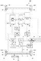
図1は、本発明の実施の形態(以下、実施形態という)にかかる複合型のブレーキ装置を搭載したハイブリッド車両の構成を示す概略図である。なお、以下の説明では、常用制動力として主として電動制動力を用いる例を示し、適宜回生制動力を利用するものとする。また、バックパップ用の制動力として液圧制動力を用いて、電動制動力や回生制動力が十分に得られない場合に、制動力を確保する例を示す。そして、図1の構成例では、制動力配分の大きな左右前輪側のブレーキ装置が電動ブレーキ機構と液圧ブレーキ機構を備える複合型のブレーキ装置であり、左右後輪側のブレーキ装置は電動ブレーキ機構のみを備える単構成型のブレーキ装置である場合を示している。もちろん、前輪および後輪を複合型のブレーキ装置としてもよいが、液圧ブレーキ機構を搭載する主たる目的は前述したように電動ブレーキ機構等の失陥時のバックアップ用なので、例えば左右前輪のみに搭載すれば十分である。前輪のみに液圧ブレーキ機構を搭載する場合、液圧配管の配管距離が短くできるというメリットがある。
Hereinafter, the best mode for carrying out the present invention will be described in detail with reference to the drawings.
FIG. 1 is a schematic diagram showing a configuration of a hybrid vehicle equipped with a composite brake device according to an embodiment of the present invention (hereinafter referred to as an embodiment). In the following description, an example in which an electric braking force is mainly used as the normal braking force is shown, and the regenerative braking force is appropriately used. In addition, an example will be shown in which a hydraulic braking force is used as a back-up braking force and the braking force is secured when an electric braking force or a regenerative braking force cannot be sufficiently obtained. In the configuration example of FIG. 1, the left and right front wheel side brake device having a large braking force distribution is a composite brake device including an electric brake mechanism and a hydraulic brake mechanism, and the left and right rear wheel side brake device is an electric brake mechanism. The case where it is a single composition type brake device provided only with this is shown. Of course, the front and rear wheels may be combined as a braking device, but the main purpose of installing the hydraulic brake mechanism is as a backup for the failure of the electric brake mechanism, etc. as described above. It is enough. When the hydraulic brake mechanism is mounted only on the front wheels, there is an advantage that the piping distance of the hydraulic piping can be shortened.
図1に示すハイブリッド車両100は、エンジン10と、エンジン10の出力軸であるクランクシャフトに接続された3軸式の動力分割機構12と、動力分割機構12に接続された発電可能なジェネレータ14と、変速機16を介して動力分割機構12に接続された走行用モータ18と、ハイブリッド車両100の駆動系全体を制御するハイブリッド用電子制御ユニット(以下、「ハイブリッドECU20」といい、電子制御ユニットは、すべて「ECU」と称する。)とを備える。変速機16には、ドライブシャフト22を介してハイブリッド車両100の右前輪24FRおよび左前輪24FLが連結される(以下、特に区別しない場合は、「前輪24」と称する)。なお、本実施形態の場合、右後輪26RRおよび左後輪26RLは従動輪となる(以下、特に区別しない場合は、「後輪26」と称する)。
A
エンジン10は、例えばガソリンや軽油等の炭化水素系燃料を用いて運転される内燃機関であり、エンジンECU28により制御される。エンジンECU28は、ハイブリッドECU20と通信可能であり、ハイブリッドECU20からの制御信号や、エンジン10の作動状態を検出する各種センサからの信号に基づいてエンジン10の燃料噴射制御や点火制御、吸気制御等を実行する。また、エンジンECU28は、必要に応じてエンジン10の作動状態に関する情報をハイブリッドECU20に与える。
The
動力分割機構12は、変速機16を介して走行用モータ18の出力を左右の前輪24FR、24FLに伝達する役割と、エンジン10の出力をジェネレータ14と変速機16とに振り分ける役割と、走行用モータ18やエンジン10の回転速度を減速あるいは増速する役割とを果たす。ジェネレータ14、走行用モータ18は、それぞれインバータを含む電力変換装置30を介してバッテリ32に接続されており、電力変換装置30には、モータECU34が接続されている。モータECU34も、ハイブリッドECU20と通信可能であり、ハイブリッドECU20からの制御信号等に基づいて電力変換装置30を介してジェネレータ14、走行用モータ18を制御する。なお、上述のハイブリッドECU20やエンジンECU28、モータECU34は、いずれもCPUを含むマイクロプロセッサとして構成されており、CPUの他に各種プログラムを記憶するROM、データを一時的に記憶するRAM、入出力ポートおよび通信ポート等を備える。
The
ハイブリッドECU20やモータECU34による制御のもと、電力変換装置30を介してバッテリ32から電力を走行用モータ18に供給することで、走行用モータ18の出力により左右の前輪24FR、24FLを駆動することができる。また、エンジン効率のよい運転領域では、ハイブリッド車両100はエンジン10によって駆動される。この際、動力分割機構12を介してエンジン10の出力の一部をジェネレータ14に伝えることにより、ジェネレータ14が発生する電力を用いて、走行用モータ18を駆動したり、電力変換装置30を介してバッテリ32を充電したりすることが可能となる。
The left and right front wheels 24FR and 24FL are driven by the output of the traveling
また、ハイブリッド車両100を制動する際には、ハイブリッドECU20やモータECU34による制御のもと、前輪24FR、24FLから伝わる動力によって走行用モータ18が回転させられ、走行用モータ18が発電機として作動させられる。すなわち、走行用モータ18、電力変換装置30、ハイブリッドECU20およびモータECU34等は、ハイブリッド車両100の運動エネルギを電気エネルギに回生することによってハイブリッド車両100を制動する回生ブレーキ機構として機能する。
Further, when braking the
本実施形態の場合、回生ブレーキ機構に加え、電動ブレーキECU40によって電動制動力が制御される電動ブレーキ機構38を各車輪ごとに有し、各車輪ごとに電動制動力の調整が可能である。電動ブレーキ機構38の構造の詳細は後述するが、モータの動作により発生する駆動力で摩擦部材を車輪と共に回転する回転体に押圧して当該回転体に対して電動制動力を付与する。例えば、電動ブレーキ機構38をディスクブレーキ装置に適用する場合、ディスクブレーキ装置のキャリパ内部にモータが内蔵される。このモータの駆動により進退するナット部材が摩擦部材であるブレーキパッドを回転体であるブレーキディスクに押圧することで電動制動力が発生する。各車輪のモータは電動ブレーキECU40によって回転量や回転方向等が制御されることにより、ドライバの要求する制動力を発生させると共に、各車輪ごとの電動制動力を制御して、例えばアンチロックブレーキ(ABS)機能等も実現する。
In the case of this embodiment, in addition to the regenerative brake mechanism, each wheel has an
ブレーキECU36、電動ブレーキECU40は、いずれもCPUを含むマイクロプロセッサとして構成されており、CPUの他に各種プログラムを記憶するROM、データを一時的に記憶するRAM、入出力ポートおよび通信ポート等を備える。ブレーキECU36、電動ブレーキECU40、ハイブリッドECU20は相互に通信可能である。ブレーキECU36には、ドライバーのブレーキペダルの踏み込み状態を検出するストロークセンサ42からの信号が入力され、その入力信号に対応する要求制動力に応じて電動制動力と回生制動力との配分比率を決定し、電動ブレーキECU40とハイブリッドECU20に対しそれぞれ制動力を要求する。このように、ブレーキECU36は、ハイブリッドECU20と電動ブレーキECU40を協調させる協調制御を実行することによりハイブリッド車両100の効率的な制動を可能にする。
Each of the
なお、本実施形態の場合、電動ブレーキECU40には、電動パーキングブレーキ(EPB)スイッチ44からのパーキング信号も入力される。電動ブレーキECU40はパーキング信号を取得すると、常用ブレーキとして機能させていた電動ブレーキ機構を電動パーキングブレーキとして機能させる。なお、パーキングブレーキ機能は、各車輪の電動ブレーキ機構38に備えてもよいし、前輪または後輪のいずれか一方に備えるようにしてもよい。
In the case of the present embodiment, a parking signal from the electric parking brake (EPB) switch 44 is also input to the
ところで、電動制動力および回生制動力は、電気制御によりその発生量を調整しているため、例えば断線等の失陥に対する対策が必要になる。そこで、本実施形態の場合、主として常用ブレーキとして機能する電動ブレーキ機構が失陥した場合等に主としてバックアップ用のブレーキ機構として機能する液圧ブレーキ機構46を右前輪24FR、左前輪24FLに備えている。ただし、本実施形態の場合、前述したように、液圧ブレーキ機構46は電動ブレーキ機構38の失陥時のバックアップ用なので、詳細な制動制御を行う必要はない。すなわち、マスタシリンダ48と右前輪24FRおよび左前輪24FLの液圧ブレーキ機構とが直結され、ブレーキペダルの踏み込み動作に対して作動液を液圧ブレーキ機構46に向けて送出するシンプルな構造のものを採用している。この場合、マスタシリンダ48から電動ブレーキ機構38のホイールシリンダに至るまでの液圧経路が短縮化し易い。その結果、配管のスペース確保や配管作業が容易になる。また、他の構成部品との干渉を回避し易く設計自由度の向上にも寄与できる。さらに、配管距離が短いため液漏れの可能性も低減され、液漏れ対策も容易になる。
By the way, since the electric braking force and the regenerative braking force are adjusted in their generation amounts by electric control, it is necessary to take measures against failure such as disconnection. Therefore, in the case of the present embodiment, the right front wheel 24FR and the left front wheel 24FL are provided with a
図示を省略しているが、ブレーキECU36には、各車輪の近傍に設けられた車輪速センサ等から車輪の回転状態に関する信号が提供される。車輪速センサからの信号に基づいて、ブレーキECU36が電動ブレーキECU40に対して送信した制動制御による制動力が各車輪において適切に発生しているかを検出し、制御に反映させることもできる。
Although not shown, the
なお、以下の説明で、電動ブレーキ機構38の失陥は、電動ブレーキ機構38を構成するモータやギアの不具合、電動ブレーキECU40からモータに至るまでの配線の断線不良、電動ブレーキECU40自体の不具合等のいずれか一つまたはその組合せによる不具合を含むものとする。
In the following description, the failure of the
図2は、実施の形態に係る電動ブレーキ機構、液圧ブレーキ機構およびマスタシリンダの内部構造を説明する概略構造図である。前述したように、本実施形態の場合、前輪24のブレーキ装置は、電動ブレーキ機構38および液圧ブレーキ機構46を備えた複合型であり、後輪26は、電動ブレーキ機構38のみを備えた単構成型である。なお、前輪24および後輪26のブレーキ装置は、左右同じ構成なので、図2の場合は、前輪24用の複合型のブレーキ装置50、後輪26用の単構成型のブレーキ装置52をそれぞれ片側のみを示している。
FIG. 2 is a schematic structural diagram illustrating the internal structure of the electric brake mechanism, the hydraulic brake mechanism, and the master cylinder according to the embodiment. As described above, in the present embodiment, the brake device for the front wheel 24 is a composite type including the
まず、電動ブレーキ機構38のみを有する単構成型のブレーキ装置52の構造を説明する。
キャリパ54は、キャリパ自身を車体側に固定するための車体固定マウント(不図示)に取り付けられ、キャリパ54は、ディスクロータ56に押圧され制動力を発生する摩擦部材であるブレーキパッド58と、ブレーキパッド58を押圧するシリンダ部60とで構成されている。車輪と共に回転する回転体であるディスクロータ56は図2に示すように、一対のブレーキパッド58の間に存在する。ディスクロータ56の側面56a、56bは摩擦摺動面を構成し、一対のブレーキパッド58がディスクロータ56を挟んで対向配置される。このブレーキパッド58は、ディスクロータ56の側面56a、56bと直接接触する摩擦材62と、この摩擦材62の裏側、すなわちディスクロータ56と接触しない側を支持するパッド裏金64によって構成されている。
First, the structure of the single-
The
キャリパ54は、図2において矢印M,N方向に変位可能に車体固定マウントを介して車体側に取り付けられている。キャリパ54のシリンダ部60には、有底の穴66が穿設されており、この穴66には、ピストン68が摺動可能に嵌挿されている。穴66の底にはピストン68を進退させる駆動力を伝達するギア列70の出力軸と接続された棒ネジ部材72の一端が回転自在に配置されている。ギア列70は複数の歯車で構成され、電動ブレーキECU40からの指令に従い回転駆動するモータ74の回転数を所定値まで減速して棒ネジ部材72を所定の回転数で所定の方向に回転させる。棒ネジ部材72には、ピストン68を進退させるためのナット部材76が噛合している。ナット部材76は棒ネジ部材72の回転により矢印M,N方向に進退する。したがって、ナット部材76が矢印M方向に移動した場合、ピストン68をパッド裏金64aに向かって移動させて、摩擦材62aをディスクロータ56の側面56aに押圧させる。摩擦材62aがディスクロータ56に押圧されると、ピストン68は摺動を停止する。ピストン68が摺動を停止した後も、棒ネジ部材72が回転してナット部材76を矢印M方向に移動させようとすると、シリンダ部60を覆っているシリンダハウジング60aが矢印N方向の反力を受けることになる。その結果、棒ネジ部材72の回転に伴って、シリンダハウジング60aが矢印N方向に変位する。
The
シリンダハウジング60aの非シリンダ形成側には爪部78が形成されており、シリンダハウジング60aの矢印N方向への変位に伴って、爪部78がパッド裏金64bを介して摩擦材62bをディスクロータ56の側面56bに押圧する。したがって、ディスクロータ56を一対の摩擦材62a,62bにより押圧挟持する状態となり、ディスクロータ56を効率的に制動させる電動制動力を発生することが可能となる。
A
電動制動力を解除する場合は、モータ74を逆転駆動させて棒ネジ部材72を制動時とは逆回転させてナット部材76を矢印N方向に退避させる。その結果、ピストン68は、ナット部材76による拘束が解除される。したがって、ブレーキパッド58のディスクロータ56に対する付勢力も解除される。この状態でディスクロータ56が回転すると、その回転によりブレーキパッド58が弾かれ離反することとなり、ディスクロータ56の自由な回転を許容する。なお、ピストン68とシリンダハウジング60aとの間には、例えば弾性部材からなるシール部材が配置されている。このシール部材は、ピストン68が矢印M方向に移動するときに弾性変形する。ピストン68は、ナット部材76による拘束が解除されると、シール部材の復元力により矢印N方向に引き戻される方向の力を受けるので、ブレーキパッド58のディスクロータ56からの離反を容易にする。
In order to release the electric braking force, the
爪部78が押圧するブレーキパッド58に、例えば、ブレーキパッド58を矢印M方向に離反させる付勢力を発生する弾性体を備えておけば制動力解放時の離反動作をスムーズに行うことができる。
For example, if the
なお、制動力の解放時に摩擦材62とディスクロータ56との隙間が大きすぎると、異物や水等の液体が侵入してしまうおそれがある。また、隙間が大きすぎると次回の制動力の発生時に遅れが生じるので好ましくない。逆に、隙間がない場合、摩擦材62がディスクロータ56に引き摺られることになり、走行抵抗の原因となり燃費(エネルギ効率)の悪化を招くおそれがある。そのため、制動力の解放時の両者の隙間は、摩擦材62とディスクロータ56との間で引き摺りが生じない程度の最小限の値にすることが望ましい。本実施形態の場合、ピストン68の退避位置はモータ74(棒ネジ部材72)の回転により正確に管理できるので、摩擦材62の引き摺り防止を容易に実現できる。また、摩擦材62は使用に伴い摩耗して薄くなるが、押圧状態からの摩擦材62の退避距離をモータ74(棒ネジ部材72)の退避量で管理できるので、摩擦材62の摩耗時における調整も容易にできる。
Note that if the clearance between the
次に、電動ブレーキ機構38と液圧ブレーキ機構46を有する複合型のブレーキ装置50の構成を説明する。
電動ブレーキ機構38の構造は、単構成型のブレーキ装置52と同じなので、同じ符号を付してその説明は省略する。複合型のブレーキ装置50のシリンダハウジング60aには、液圧ブレーキ機構46を動作させるための作動液をシリンダ部60に導入するために導入ポート80が形成されている。導入ポート80には、マスタシリンダ48の送出ポート82から延びる液圧配管84が接続されている。マスタシリンダ48から作動液が送出され、シリンダ部60内部に注入されると、穴66内部の圧力が高まりピストン68を矢印M方向に移動させる。ピストン68の移動によるブレーキパッド58、シリンダハウジング60a、爪部78等の挙動は前述した電動ブレーキ機構における挙動と同じであり、制動力、すなわち液圧制動力が発生できる。
Next, the structure of the
Since the structure of the
マスタシリンダ48は、シリンダ室48aを有し、内部にブレーキペダル86から延びるプッシュロッドが接続されたマスタピストン88が摺動自在に配置されている。マスタピストン88は、スプリング48bの弾性力を受けてブレーキペダル86が踏み込まれていないときにブレーキペダル86を初期位置側に戻すようにプッシュロッドを押圧している。ドライバによってブレーキペダル86が踏み込まれると、プッシュロッドがマスタシリンダ48に進入し、マスタピストン88が押圧される。これにより、シリンダ室48aにマスタシリンダ圧が発生可能となる。マスタシリンダ48には、作動液90(ブレーキフルード)を貯留しておくリザーバ92が接続され、常時シリンダ室48aが作動液90で満たされるようにしている。
The
ブレーキペダル86には、ストロークセンサ42が設けられ、ブレーキペダル86がドライバにより踏み込まれたときの踏み込み状態を検出して、その信号をブレーキECU36に送信する。ブレーキECU36では、ストロークセンサ42の信号に基づいてドライバの要求制動力を算出して、電動ブレーキECU40やハイブリッドECU20を協調制御して適切な制動力を発生させる。
The
なお、本実施形態の場合、電動ブレーキ機構38を電動パーキングブレーキとしても機能させることができる。図2に示すように、電動ブレーキ機構38の場合、棒ネジ部材72とナット部材76が噛合していると共に棒ネジ部材72とモータ74との間にはギア列70が存在するので、モータ74への電流供給が停止したとしても棒ネジ部材72が制動力解放方向に回転する可能性は低い。したがって、ナット部材76によるピストン68の押圧状態が維持され、パーキングブレーキとしての制動力を維持できる。ただし、本実施形態の場合、パーキング時の制動力維持を確実なものにするため、EPBスイッチ44が操作され、パーキングが有効になった場合に、ブレーキ装置50の例えばモータ74の出力ギアに楔を打ち込むパーキング用ソレノイド44aを備えている。パーキング用ソレノイド44aにより楔を打ち込むことにより、各ギアの遊び等による緩みの発生が抑制され、パーキング制動力の維持を保証することができる。
In the present embodiment, the
ところで、本実施形態のマスタシリンダ48には、当該マスタシリンダ48内の作動液90をリザーバ92に排出する排出ポート94が形成されている。排出ポート94はマスタシリンダ48において、マスタピストン88の侵入側とは逆側の終端位置に偏った位置に形成されている。排出ポート94にはリザーバ92から延びる排出配管96が接続され、その排出配管96の経路中にマスタシリンダ48からリザーバ92に排出する作動液90の排出調整をする調整機構として機能するバルブ98が配置されている。バルブ98は例えば、常閉型の開閉弁であり、非通電の場合に閉弁し、通電により開弁する。バルブ98の開閉制御は、例えば電動ブレーキECU40によって行われる。バルブ98が開弁状態の場合にブレーキペダル86が踏み込まれてマスタピストン88が矢印M方向に移動しても作動液90は、リザーバ92に排出されるためシリンダ室48aの圧力は上がらず、ブレーキ装置50に向けて送出されることはない。つまり、ブレーキ装置50の液圧ブレーキ機構による液圧制動力は発生しない。一方、バルブ98が閉弁状態の場合にブレーキペダル86が踏み込まれてマスタピストン88が矢印M方向に移動すると作動液90は、リザーバ92に排出されないためシリンダ室48aの圧力が上がり、ブレーキ装置50に向けて送出される。つまり、ブレーキ装置50の液圧ブレーキ機構による液圧制動力が発生することになる。
Incidentally, the
このように構成されるブレーキ装置の基本的な動作を説明する。前述したように、本実施形態のブレーキ装置は、電動ブレーキ機構38を主に用いて制動力を発生させる。そして、電動ブレーキ機構38に失陥が生じて電動制動力が十分に発生できない場合等に、バックアップとして液圧ブレーキ機構46が動作するようにして液圧制動力により制動力を確保する。したがって、電動ブレーキ機構38が正常に動作している場合には、バルブ98を開弁状態にして排出ポート94から作動液90を排出させ、リザーバ92に送る。その結果、ドライバがブレーキペダル86を踏み込んでも、その踏み込み動作に起因する液圧制動力は基本的には発生しない。つまり、ストロークセンサ42の検出値に基づく要求制動力が液圧制動力以外で賄われる。図3(a)は、電動ブレーキ機構38が正常動作している場合のブレーキペダル86のストロークと発生する制動力の関係を示している。本実施形態の場合、排出ポート94がマスタシリンダ48のストローク終端から僅かにストローク始端側に偏った位置に形成されている。したがって、ブレーキペダル86の踏み込みよりマスタピストン88がストロークして、当該マスタピストン88で排出ポート94を塞ぐまでは液圧制動力は発生しない。つまり、図3(a)に示すように、電動制動力のみが発生し、排出ポート94の形成位置であるA点を超えて液圧制動力が発生し始める。このように、電動制動力を主な制動力として利用することができる。なお、制動力立ち上がりの遅れは、ブレーキペダル86の遊びに対応する遅れである。
The basic operation of the brake device configured as described above will be described. As described above, the brake device of the present embodiment generates a braking force mainly using the
図3(a)に示すように、A点を通過した時点で液圧制動力を発生させることにより、例えばABS制御を行う場合のペダル反力を発生させることができる。本実施形態の場合、ABS制御を行う場合も基本的には電動ブレーキ機構38による制動力の増減制御で行う。この場合、電動制動力のみでABS制御を行うと、通常の液圧制動力を常用制動力にしている場合にABS制御中であることをドライバに認識させる一手段となるペダル反力が発生できない。一方、図3(a)に示すように、ABS制御が実行されやすいブレーキペダル86の踏み込み量が大きいときに液圧制動力を発生させることにより、制動力の増減に伴う作動液90の脈動を液圧配管84およびマスタシリンダ48を介してブレーキペダル86に伝達することができる。なお、図2の場合、排出ポート94はストローク終端に近い位置に形成されているので、電動ブレーキ機構38の正常動作時にABS制御が実行されても発生する液圧制動力は僅かであり、電動制動力の増減調整で液圧制動力の発生を相殺できるのでABS制御はスムーズに実行できる。
As shown in FIG. 3 (a), by generating a hydraulic braking force when passing through point A, it is possible to generate, for example, a pedal reaction force when performing ABS control. In the case of the present embodiment, the ABS control is basically performed by the braking force increase / decrease control by the
一方、電動ブレーキ機構38において、断線等の失陥が生じて電動制動力が発生できない場合、電動ブレーキECU40はバルブ98に対する通電を止める。その結果、マスタシリンダ48内の作動液90は排出配管96を介してリザーバ92に排出されない。その結果、図3(b)に示すように、ブレーキペダル86の踏み込みの初期の段階から液圧制動力を発生させることができる。
On the other hand, in the
このように、排出ポート94を形成するシンプルな構成により、電動ブレーキ機構38の正常動作時には電動制動力を主に利用し、電動ブレーキ機構38の失陥時には、液圧制動力をバックアップ用の制動力として利用することができる。なお、電動ブレーキ機構38の失陥は、例えば、電動ブレーキECU40により断線判定や各センサによる異常判定、通電時間の異常等によって検出することができる。
As described above, the simple configuration that forms the
図2の場合、排出ポート94をストローク終端から僅かに離れた位置に形成した例を示したが、この位置は適宜変更してもよい。例えば、電動ブレーキ機構38の異常判定が迅速に行える場合は、排出ポート94の位置をストローク終端位置にしてもよい。この場合、電動ブレーキ機構38の正常時は完全に液圧制動力を利用しない構成にすることができる。逆に、排出ポート94の位置を図2のように矢印N方向に偏らせれば、電動ブレーキ機構38が正常動作時でも、液圧制動力を補助制動力として利用することが可能になる。例えば、急ブレーキを踏んだ場合には、液圧制動力の発生を早めて電動制動力と液圧制動力により制動力を発生させることができる。また、電動ブレーキ機構38の失陥時に何らかの原因によりバルブ98の閉弁が遅れるような場合でもマスタピストン88により排出ポート94を塞いだ時点から液圧制動力の発生が可能になる。
In the case of FIG. 2, the example in which the
なお、電動ブレーキ機構38の失陥によりバルブ98が閉弁された場合、電動ブレーキ機構38が失陥した旨をドライバに迅速に通知することが望ましく、例えば表示灯や音声により警報を出力して速やかに修理等で対応することを促すことが望ましい。
In addition, when the
このように構成されるブレーキ装置を図1のハイブリッド車両100に搭載した場合の制御例を図4のフローチャートを用いて説明する。
まず、ハイブリッド車両100のイグニッションスイッチがONの場合、ブレーキECU36は所定周期でシステムチェックを行う(S100)。この場合、ブレーキECU36は、電動ブレーキECU40およびハイブリッドECU20を介してそれぞれのシステムの動作確認を実行する。続いて、ブレーキECU36は、ブレーキペダル86の踏み込みによりドライバから制動要求があった場合であり(S102のY)、電動ブレーキ機構38が正常に動作可能な場合は(S104のY)、バルブ98を開弁する(S106)。バルブ98を常閉型の開閉弁にした場合、電動ブレーキECU40は電動ブレーキ機構38の正常動作時は常時通電により開弁しているので、その状態を維持することなる。そして、ブレーキECU36は、ハイブリッドECU20との通信により回生制動力の発生が可能である場合(S108のY)、電動ブレーキECU40とハイブリッドECU20の協調制御により要求制動力を発生するように、電動制動力および回生制動力の制御を行う(S110)。図5(a)は、電動ブレーキ機構38が正常動作している場合であり、電動制動力と回生制動力により、図2のA点まで協調制御が行われている様子が示されている。さらに、ブレーキペダル86の踏み込みが進みマスタピストン88が排出ポート94を通過した時点から電動制動力と回生制動力に加え液圧制動力が発生している様子を示している。この場合、回生制動力の発生分だけ、電動制動力の発生を抑制できるので電動ブレーキ機構38を駆動するための電力消費を軽減できる。なお、排出ポート94をストロークの終端に形成すれば、液圧制動力の追加発生が生じないようにできる。
A control example when the brake device configured as described above is mounted on the
First, when the ignition switch of the
S108において、例えばバッテリ32が満充電等の原因により回生制動力が発生できない場合(S108のN)、ブレーキECU36は電動ブレーキECU40により電動制動力のみを発生させる電動制動力制御を実行する(S112)。図5(b)に示すように、この場合もブレーキペダル86の踏み込みが進みマスタピストン88が排出ポート94を通過した時点から電動制動力に加え液圧制動力が発生するが、排出ポート94をストロークの終端に形成すれば、液圧制動力の追加発生が生じないようにできる。
In S108, for example, when the
S104において、電動ブレーキ機構38に失陥が生じている場合で(S104のN)、回生制動力の発生が可能である場合(S114のY)、ブレーキECU36は、要求制動力と発生可能な回生制動力を比較する。そして、回生制動力のみで十分に制動力を賄える場合(回生制動力で要求制動力を完全に賄えない場合でも十分安全な制動が行える場合も含む)で、液圧制動力の補助が不要な場合(S116のY)、バルブ98を開弁する(S118)。すなわち電動ブレーキECU40はバルブ98に対する通電を継続して開弁状態を維持する。そして、ブレーキECU36は、ハイブリッドECU20を制御して要求制動力を発生するように回生制動力制御を実行する(S120)。図5(c)に示すように、この場合もブレーキペダル86の踏み込みが進みマスタピストン88が排出ポート94を通過した時点から回生制動力に加え液圧制動力が発生するが、排出ポート94をストロークの終端に形成すれば、液圧制動力の追加発生が生じないようにできる。
In S104, when the
S116において、要求制動力より発生できる回生制動力が少ない場合、つまり要求制動力を賄うために液圧制動力の追加が必要な場合(S116のN)、電動ブレーキECU40は、バルブ98に対する通電を中止して閉弁状態とする(S122)。その結果、排出ポート94からリザーバ92へ作動液90の排出が抑制される。つまり、ブレーキペダル86の踏み込み初期の段階から液圧制動力の発生が可能になる。ブレーキECU36は、ハイブリッドECU20を制御して回生制動力制御を実行すると共に、ブレーキペダル86の踏み込み量に応じた液圧制動力のバックアップ制御を実行する(S124)。この場合の制動力の発生の様子を図5(d)に示す。このように、電動ブレーキ機構38の失陥時に急峻なブレーキペダル86の操作が行われた場合でも、可能な限りの制動力を発生させて制動力と応答性の確保を実現する。
In S116, when the regenerative braking force that can be generated from the required braking force is small, that is, when the hydraulic braking force needs to be added to cover the required braking force (N in S116), the
S114において、電動制動力に加え、回生制動力も発生できない場合(S114のN)、電動ブレーキECU40は、バルブ98に対する通電を中止して閉弁状態とする(S126)。その結果、排出ポート94からリザーバ92へ作動液90の排出が抑制される。つまり、ブレーキペダル86の踏み込み初期の段階から液圧制動力の発生が可能になる。その結果、ブレーキペダル86の踏み込み量に応じた液圧制動力のバックアップ制御を実行する(S128)。この場合の制動力の発生の様子を図5(e)に示す。このように、電動ブレーキ機構38の失陥時で回生制動力も発生できない場合でも、可能な限りの制動力を発生させて制動力と応答性の確保を実現する。
In S114, when the regenerative braking force cannot be generated in addition to the electric braking force (N in S114), the
S102において、制動要求がない場合は(S102のN)、S100に戻り、次の周期での処理を実行する。 In S102, when there is no braking request (N in S102), the process returns to S100 and the process in the next cycle is executed.
上述した例では、バルブ98を単純な開閉動作を行う電磁バルブとしたが、開閉度を詳細に制御できるリニアバルブとしてもよい。リニアバルブの場合、全開および全閉の場合は、バルブ98と同様に排出ポート94からのリザーバ92への作動液90の排出時期の制御ができる。また、開閉量を制御することにより液圧制動力を発生させる場合の液圧制動力の大きさの制御ができる。例えば、上述したバルブ98の場合、電動ブレーキ機構38が正常動作時にABS制御が実施された場合、マスタピストン88が排出ポート94を塞がなければペダル反力が得られない。一方、リニアバルブにして、排出ポート94からリザーバ92への作動液90の排出量を制御することで、作動液90の脈動をブレーキペダル86側に伝達し易くしてドライバにペダル反力の変化を感じさせるようにできる。
In the above-described example, the
また、上述の実施形態では、電動ブレーキ機構38が正常動作しており、回生制動力が発生できるか否かに拘わらず、バルブ98を開弁状態にしてマスタピストン88が排出ポート94を塞ぐまで液圧制動力を発生しない場合を示した。別の実施例では、電動ブレーキ機構38が正常動作している場合、回生制動力が発生できるか否かに拘わらず、最初からバルブ98を閉じて液圧制動力を発生できるようにしてもよい。この場合、液圧制動力の発生分だけ、電動制動力の発生量を軽減できるので、電動ブレーキ機構38を動作させるための電力消費を低減できる。
In the above-described embodiment, the
また、上述した実施形態では、排出ポート94の排出を制御するバルブ98を備える例を示したが、バルブ98を省略してもよい。つまり、ブレーキペダル6が所定量踏み込まれるまで(例えばA点まで)、マスタシリンダ48内の作動液90をリザーバ92に排出して電動制動力の発生開始より液圧制動力の発生開始を遅らせるようにする。この場合、ブレーキペダル86の踏み込み量がA点を超えれば作動液90が液圧ブレーキ機構46に送出され液圧制動力を発生させることが可能になる。その結果、電動ブレーキ機構38の失陥時に電動制動力が発生しない場合でもブレーキペダル86を排出ポート94を越える位置まで踏み込めば、液圧ブレーキ機構46がバックアップ用ブレーキ装置として機能するよりシンプルな構成のブレーキ装置が構成できる。
In the above-described embodiment, the example in which the
また、上述した実施形態では、電動ブレーキ機構38の失陥を電動ブレーキECU40で検出する例を示したが、例えばブレーキECU36がストロークセンサ42から取得した要求制動力と、キャリパ54等の内部に配置されたセンサからの信号に基づいて算出した制動力発生推定量と比較して、その推定量がブレーキペダル86の操作に対応する制動力に満たない場合、バルブ98の開閉制御を行い液圧制動力の発生量を制御してもよい。この場合、電動ブレーキECU40自体が失陥した場合でも液圧制動力をバックアップ用の制動力として迅速に発生させることができる。
Further, in the above-described embodiment, the example in which the failure of the
上述した実施形態では、ハイブリッド車両100に排出ポート94を有するブレーキ装置を搭載した例を示したが、別の実施例では、エンジンを搭載しない電気自動車に本実施形態のブレーキ装置を適用して本実施形態と同様の効果を得ることができる。また、走行用モータを含まない車両に適用した場合は、回生制動力の付加がなくなるのみで、本実施形態と同様の効果を得ることができる。
また、図2の例では、ブレーキ装置としてディスクブレーキ装置を示したが、ドラムブレーキ装置に適用しても本実施形態と同様の効果を得ることができる。
In the above-described embodiment, an example in which the brake device having the
In the example of FIG. 2, the disc brake device is shown as the brake device. However, the same effect as that of the present embodiment can be obtained even if the disc brake device is applied to the drum brake device.
以上、本発明を上述の実施形態を参照して説明したが、本発明は上述の実施形態に限定されるものではなく、実施形態や変形例の構成を適宜組み合わせたものや置換したものについても本発明に含まれるものである。また、当業者の知識に基づいて各種の設計変更等の変形を実施形態に対して加えることも可能であり、そのような変形が加えられた実施形態も本発明の範囲に含まれうる。 As described above, the present invention has been described with reference to the above-described embodiment. However, the present invention is not limited to the above-described embodiment, and the present invention is not limited to the above-described embodiment and may be appropriately combined or replaced with the configurations of the embodiment and the modified examples. It is included in the present invention. Various modifications such as design changes can be added to the embodiments based on the knowledge of those skilled in the art, and embodiments to which such modifications are added can be included in the scope of the present invention.
20 ハイブリッドECU、 36 ブレーキECU、 38 電動ブレーキ機構、 40 電動ブレーキECU、 42 ストロークセンサ、 46 液圧ブレーキ機構、 48 マスタシリンダ、 50,52 ブレーキ装置、 74 モータ、 86 ブレーキペダル、 90 作動液、 92 リザーバ、 94 排出ポート、 100 ハイブリッド車両。 20 Hybrid ECU, 36 Brake ECU, 38 Electric brake mechanism, 40 Electric brake ECU, 42 Stroke sensor, 46 Hydraulic brake mechanism, 48 Master cylinder, 50, 52 Brake device, 74 Motor, 86 Brake pedal, 90 Hydraulic fluid, 92 Reservoir, 94 discharge port, 100 hybrid vehicle.
Claims (3)
作動液の供給により発生する駆動力で前記摩擦部材を前記回転体に押圧して当該回転体に対する液圧制動力を付与する液圧ブレーキ機構と、
ドライバが操作するブレーキペダルの操作量に応じて前記電動ブレーキ機構により前記電動制動力を発生させる制御部と、
前記ブレーキペダルの操作量に応じて容積が変化すると共に、その容積の減少により前記作動液を前記液圧ブレーキ機構に向けて送出可能なマスタシリンダと、
前記作動液を貯留するリザーバと、
前記マスタシリンダから前記リザーバに排出する前記作動液の排出調整をする調整機構と、
を含み、
前記マスタシリンダは、当該マスタシリンダ内の前記作動液を前記リザーバに排出する排出ポートを有し、
前記調整機構は、前記排出ポートと前記リザーバとの間の前記作動液の流路に設けられ、
前記排出ポートは、前記ブレーキペダルが所定量踏み込まれるまで、前記マスタシリンダ内の前記作動液を前記リザーバに排出し、前記ブレーキペダルが所定量より踏み込まれると閉じられ、
前記マスタシリンダは、前記排出ポートが前記ブレーキペダルの所定量を超える踏み込みにより閉じられた場合、前記作動液を前記液圧ブレーキ機構に送出して液圧制動力を発生させることを特徴とするブレーキ装置。 An electric brake mechanism that applies an electric braking force to the rotating body by pressing the friction member against the rotating body rotating together with the wheels with a driving force generated by the operation of the motor;
A hydraulic brake mechanism that applies a hydraulic braking force to the rotating body by pressing the friction member against the rotating body with a driving force generated by supplying hydraulic fluid;
A control unit that generates the electric braking force by the electric brake mechanism according to an operation amount of a brake pedal operated by a driver;
A master cylinder capable of changing the volume according to the operation amount of the brake pedal and sending the hydraulic fluid toward the hydraulic brake mechanism by reducing the volume;
A reservoir for storing the hydraulic fluid;
An adjustment mechanism for adjusting the discharge of the hydraulic fluid discharged from the master cylinder to the reservoir;
Including
The master cylinder, have a discharge port for discharging the hydraulic fluid in the master cylinder to said reservoir,
The adjustment mechanism is provided in a flow path of the hydraulic fluid between the discharge port and the reservoir,
The discharge port discharges the hydraulic fluid in the master cylinder to the reservoir until the brake pedal is depressed by a predetermined amount, and is closed when the brake pedal is depressed from a predetermined amount,
The master cylinder generates a hydraulic braking force by sending the hydraulic fluid to the hydraulic brake mechanism when the discharge port is closed by depression of a predetermined amount of the brake pedal. .
前記制御部は、前記電動制動力と前記回生制動力の総計による制動力が前記ブレーキペダルの操作に対応する制動力に満たない場合、前記調整機構の制御を行い前記液圧制動力の発生量を制御することを特徴とする請求項1または2記載のブレーキ装置。 A regenerative braking mechanism for generating a regenerative braking force by regeneratively driving a motor capable of supplying a driving force to the wheels;
The control unit controls the adjustment mechanism to reduce the generation amount of the hydraulic braking force when the braking force based on the sum of the electric braking force and the regenerative braking force is less than the braking force corresponding to the operation of the brake pedal. The brake device according to claim 1 , wherein the brake device is controlled.
Priority Applications (5)
| Application Number | Priority Date | Filing Date | Title |
|---|---|---|---|
| JP2012063988A JP5960461B2 (en) | 2012-03-21 | 2012-03-21 | Brake device |
| PCT/IB2013/000386 WO2013140221A1 (en) | 2012-03-21 | 2013-03-15 | Brake device |
| US14/384,474 US20150115697A1 (en) | 2012-03-21 | 2013-03-15 | Brake device |
| CN201380015100.5A CN104203665B (en) | 2012-03-21 | 2013-03-15 | Brake apparatus |
| EP13718887.6A EP2828132B1 (en) | 2012-03-21 | 2013-03-15 | Brake device |
Applications Claiming Priority (1)
| Application Number | Priority Date | Filing Date | Title |
|---|---|---|---|
| JP2012063988A JP5960461B2 (en) | 2012-03-21 | 2012-03-21 | Brake device |
Publications (2)
| Publication Number | Publication Date |
|---|---|
| JP2013193606A JP2013193606A (en) | 2013-09-30 |
| JP5960461B2 true JP5960461B2 (en) | 2016-08-02 |
Family
ID=48190541
Family Applications (1)
| Application Number | Title | Priority Date | Filing Date |
|---|---|---|---|
| JP2012063988A Expired - Fee Related JP5960461B2 (en) | 2012-03-21 | 2012-03-21 | Brake device |
Country Status (5)
| Country | Link |
|---|---|
| US (1) | US20150115697A1 (en) |
| EP (1) | EP2828132B1 (en) |
| JP (1) | JP5960461B2 (en) |
| CN (1) | CN104203665B (en) |
| WO (1) | WO2013140221A1 (en) |
Families Citing this family (17)
| Publication number | Priority date | Publication date | Assignee | Title |
|---|---|---|---|---|
| FR3044992B1 (en) * | 2015-12-15 | 2019-05-31 | Foundation Brakes France | METHOD FOR CONTROLLING A BRAKING SYSTEM CAPABLE OF REALIZING THE PARKING BRAKE FUNCTION |
| JP6544261B2 (en) | 2016-02-16 | 2019-07-17 | トヨタ自動車株式会社 | Brake system |
| US10569657B2 (en) * | 2016-02-16 | 2020-02-25 | Toyota Jidosha Kabushiki Kaisha | Vehicle brake system |
| ITUA20163189A1 (en) * | 2016-05-05 | 2017-11-05 | Freni Brembo Spa | Brake disc monitoring system of a vehicle's brake system |
| DE102016214219A1 (en) * | 2016-08-02 | 2018-02-08 | Robert Bosch Gmbh | Method for servicing a brake system with hydraulic vehicle brake and electromechanical brake device |
| DE102017111077A1 (en) * | 2017-05-22 | 2018-11-22 | Lsp Innovative Automotive Systems Gmbh | Braking device, in particular for electrically driven motor vehicles |
| JP7021921B2 (en) * | 2017-12-04 | 2022-02-17 | 日立Astemo株式会社 | Brake system |
| US10870419B2 (en) * | 2018-07-20 | 2020-12-22 | Continental Automotive Systems, Inc. | EPB low residual torque software function |
| DE102018213284A1 (en) * | 2018-08-08 | 2020-02-13 | Continental Teves Ag & Co. Ohg | Brake system for a motor vehicle |
| EP3898358B1 (en) * | 2018-12-20 | 2023-06-07 | Ipgate Ag | Redundant brake system with pressure supply for electric vehicle and vehicle with category 3 to 4 autonomous drive |
| DE102018133223A1 (en) * | 2018-12-20 | 2020-06-25 | Ipgate Ag | Vehicle axle with electric drive motors and electro-hydraulic brakes and other modules such as gears, torque vectoring and parking brakes |
| CN109823188A (en) * | 2019-01-10 | 2019-05-31 | 乾碳国际公司 | The mixed gentle speed system of dynamic commercial vehicle regenerative braking |
| CN109733368B (en) * | 2019-01-18 | 2021-05-25 | 江苏大学 | Failure-preventing brake-by-wire system and control method thereof |
| JP7147652B2 (en) * | 2019-03-22 | 2022-10-05 | トヨタ自動車株式会社 | vehicle braking controller |
| CN111619534A (en) * | 2020-05-25 | 2020-09-04 | 奇瑞汽车股份有限公司 | Distributed automobile braking system, braking method and automobile |
| KR20210148633A (en) * | 2020-06-01 | 2021-12-08 | 현대모비스 주식회사 | Electrohydraulic Brake |
| CN112543720B (en) * | 2020-07-03 | 2021-12-14 | 华为技术有限公司 | Pedal feel adjusting device and control method |
Family Cites Families (27)
| Publication number | Priority date | Publication date | Assignee | Title |
|---|---|---|---|---|
| JPS6033083Y2 (en) * | 1976-11-16 | 1985-10-02 | トヨタ自動車株式会社 | Pedal stopper device |
| DE3635846C2 (en) * | 1986-10-22 | 1995-08-03 | Teves Gmbh Alfred | Anti-lock brake system with traction control |
| US5423600A (en) * | 1994-02-14 | 1995-06-13 | General Motors Corporation | Brake system with brake gain shifting |
| JP3546277B2 (en) * | 1996-01-29 | 2004-07-21 | トヨタ自動車株式会社 | Electric vehicle braking system |
| JPH11280797A (en) * | 1998-03-26 | 1999-10-15 | Tokico Ltd | Motor-driven brake device |
| JP2001158343A (en) * | 1999-11-30 | 2001-06-12 | Takashi Yamaguchi | Automotive brake intensifier |
| JP4320968B2 (en) * | 2000-05-02 | 2009-08-26 | トヨタ自動車株式会社 | Brake system |
| JP3945387B2 (en) * | 2002-11-26 | 2007-07-18 | 株式会社日立製作所 | ELECTRIC BRAKE, ITS CONTROL DEVICE, AND ELECTRIC BRAKE CONTROL METHOD |
| JP4134706B2 (en) * | 2002-12-10 | 2008-08-20 | 日産自動車株式会社 | Braking device for vehicle |
| JP3914172B2 (en) * | 2003-05-27 | 2007-05-16 | 本田技研工業株式会社 | Braking device for four-wheeled vehicle |
| WO2005014352A1 (en) * | 2003-08-06 | 2005-02-17 | Continental Teves Ag & Co.Ohg | Electrohydraulic brake system for motor vehicles |
| US7252282B2 (en) * | 2005-02-15 | 2007-08-07 | Delphi Technologies, Inc. | Armature with vent passages for vehicle actuator |
| US7393065B2 (en) * | 2006-06-01 | 2008-07-01 | Lockheed Martin Corporation | Redundant braking system |
| JP4375376B2 (en) * | 2006-09-14 | 2009-12-02 | トヨタ自動車株式会社 | Braking force control device |
| JP5206952B2 (en) * | 2007-08-31 | 2013-06-12 | 日立オートモティブシステムズ株式会社 | Disc brake device |
| JP5187107B2 (en) | 2007-10-19 | 2013-04-24 | 日産自動車株式会社 | Disc brake |
| CN101903228B (en) * | 2007-12-20 | 2014-06-18 | 标致·雪铁龙汽车公司 | Braking method for hybrid vehicles compensating for an electric braking torque |
| JP4623090B2 (en) * | 2007-12-25 | 2011-02-02 | トヨタ自動車株式会社 | Brake control device |
| US20090240414A1 (en) * | 2008-03-20 | 2009-09-24 | Gm Global Technology Operations, Inc. | Brake noise suppression via system pressure modulation |
| DE102009033499A1 (en) * | 2008-07-18 | 2010-01-21 | Continental Teves Ag & Co. Ohg | Brake system for motor vehicles |
| DE102009026960A1 (en) * | 2008-12-18 | 2010-07-01 | Robert Bosch Gmbh | Method for controlling a brake application of a hybrid vehicle |
| JP2010241389A (en) | 2009-04-10 | 2010-10-28 | Toyota Motor Corp | Electric brake device |
| EP2495143B1 (en) * | 2009-10-28 | 2014-11-26 | Toyota Jidosha Kabushiki Kaisha | Brake control system |
| JP5368954B2 (en) * | 2009-12-03 | 2013-12-18 | 本田技研工業株式会社 | Vehicle braking system |
| JP2011245927A (en) * | 2010-05-25 | 2011-12-08 | Advics Co Ltd | Hydraulic pressure generating device |
| DE102011084206A1 (en) * | 2010-10-12 | 2012-04-12 | Continental Teves Ag & Co. Ohg | Brake system for motor vehicles |
| US8721009B1 (en) * | 2011-06-02 | 2014-05-13 | Advent Aerospace, Inc. | Anti-skid braking system for an aircraft |
-
2012
- 2012-03-21 JP JP2012063988A patent/JP5960461B2/en not_active Expired - Fee Related
-
2013
- 2013-03-15 EP EP13718887.6A patent/EP2828132B1/en not_active Not-in-force
- 2013-03-15 WO PCT/IB2013/000386 patent/WO2013140221A1/en active Application Filing
- 2013-03-15 CN CN201380015100.5A patent/CN104203665B/en not_active Expired - Fee Related
- 2013-03-15 US US14/384,474 patent/US20150115697A1/en not_active Abandoned
Also Published As
| Publication number | Publication date |
|---|---|
| EP2828132B1 (en) | 2016-09-14 |
| CN104203665A (en) | 2014-12-10 |
| EP2828132A1 (en) | 2015-01-28 |
| CN104203665B (en) | 2016-11-02 |
| JP2013193606A (en) | 2013-09-30 |
| US20150115697A1 (en) | 2015-04-30 |
| WO2013140221A1 (en) | 2013-09-26 |
Similar Documents
| Publication | Publication Date | Title |
|---|---|---|
| JP5960461B2 (en) | Brake device | |
| JP5066004B2 (en) | Brake system | |
| EP2428416B1 (en) | Vehicle braking device | |
| JP6317804B2 (en) | Brake system for vehicles with electric brake booster | |
| US8794719B2 (en) | Brake device for vehicle | |
| CN109383477B (en) | Vehicle brake system | |
| JP2014051285A (en) | Brake device of automobile, hydraulic device therefor, and operation method of brake device | |
| CN103189253A (en) | Method for operating a brake system, brake systems in which the method is carried out and motor vehicles comprising said brake systems | |
| JP2008030599A (en) | Electric booster | |
| EP2957471B1 (en) | Vehicle brake device | |
| US9765763B2 (en) | Device for receiving and dispensing hydraulic fluid, in particular for a hybrid or electric vehicle, and braking system for a hybrid or electric vehicle | |
| JP3348773B2 (en) | Vehicle travel control device | |
| JP2017171215A (en) | Brake system | |
| JP2011131886A (en) | Electric booster | |
| JP6745739B2 (en) | Brake system | |
| KR20110072387A (en) | Regenerative braking system for vehicle | |
| JP2009067320A (en) | Vehicular braking device | |
| KR20150099937A (en) | Brake system of hybrid electric vehicle | |
| JP2010215069A (en) | Bbw type brake device | |
| JP2003002183A (en) | Brake device | |
| JP5474132B2 (en) | Brake system | |
| KR102036900B1 (en) | Electric brake system | |
| KR101683852B1 (en) | Hybrid brake system for vehicle | |
| US20240025381A1 (en) | Method for a driver assistance system for releasing an electro-hydraulic parking brake | |
| KR20090030946A (en) | Stroke adjustment device in booster master cylinder for an automobile |
Legal Events
| Date | Code | Title | Description |
|---|---|---|---|
| A621 | Written request for application examination |
Free format text: JAPANESE INTERMEDIATE CODE: A621 Effective date: 20150115 |
|
| A977 | Report on retrieval |
Free format text: JAPANESE INTERMEDIATE CODE: A971007 Effective date: 20151210 |
|
| A131 | Notification of reasons for refusal |
Free format text: JAPANESE INTERMEDIATE CODE: A131 Effective date: 20160202 |
|
| A521 | Request for written amendment filed |
Free format text: JAPANESE INTERMEDIATE CODE: A523 Effective date: 20160324 |
|
| TRDD | Decision of grant or rejection written | ||
| A01 | Written decision to grant a patent or to grant a registration (utility model) |
Free format text: JAPANESE INTERMEDIATE CODE: A01 Effective date: 20160531 |
|
| A61 | First payment of annual fees (during grant procedure) |
Free format text: JAPANESE INTERMEDIATE CODE: A61 Effective date: 20160623 |
|
| R151 | Written notification of patent or utility model registration |
Ref document number: 5960461 Country of ref document: JP Free format text: JAPANESE INTERMEDIATE CODE: R151 |
|
| R250 | Receipt of annual fees |
Free format text: JAPANESE INTERMEDIATE CODE: R250 |
|
| R250 | Receipt of annual fees |
Free format text: JAPANESE INTERMEDIATE CODE: R250 |
|
| LAPS | Cancellation because of no payment of annual fees |