JP5959226B2 - Game machine - Google Patents

Game machine Download PDF

Info

Publication number
JP5959226B2
JP5959226B2 JP2012036800A JP2012036800A JP5959226B2 JP 5959226 B2 JP5959226 B2 JP 5959226B2 JP 2012036800 A JP2012036800 A JP 2012036800A JP 2012036800 A JP2012036800 A JP 2012036800A JP 5959226 B2 JP5959226 B2 JP 5959226B2
Authority
JP
Japan
Prior art keywords
game
main control
game operation
control cpu
stopped
Prior art date
Legal status (The legal status is an assumption and is not a legal conclusion. Google has not performed a legal analysis and makes no representation as to the accuracy of the status listed.)
Active
Application number
JP2012036800A
Other languages
Japanese (ja)
Other versions
JP2013169424A (en
JP2013169424A5 (en
Inventor
矢次 譲
譲 矢次
Original Assignee
株式会社藤商事
Priority date (The priority date is an assumption and is not a legal conclusion. Google has not performed a legal analysis and makes no representation as to the accuracy of the date listed.)
Filing date
Publication date
Application filed by 株式会社藤商事 filed Critical 株式会社藤商事
Priority to JP2012036800A priority Critical patent/JP5959226B2/en
Publication of JP2013169424A publication Critical patent/JP2013169424A/en
Publication of JP2013169424A5 publication Critical patent/JP2013169424A5/ja
Application granted granted Critical
Publication of JP5959226B2 publication Critical patent/JP5959226B2/en
Active legal-status Critical Current
Anticipated expiration legal-status Critical

Links

Images

Description

本発明は、パチンコ機、アレンジボール機、雀球遊技機、スロットなどの遊技機に関し、より詳しくは、ノイズ等の誤作動で遊技動作が停止した場合であっても、遊技者に不利益を与えることなく遊技動作を再開できる遊技機に関する。   The present invention relates to a gaming machine such as a pachinko machine, an arrangement ball machine, a sparrow ball game machine, and a slot, and more particularly, even if the gaming operation is stopped due to a malfunction such as noise, the player is disadvantaged. The present invention relates to a gaming machine that can resume a gaming operation without giving it.

従来の遊技機として、例えば特許文献1に記載のような遊技機が知られている。この遊技機は、不正行為を検知して不正検知信号を発信する不正検知センサを備えており、この不正検知センサによって不正を検知すると遊技動作の進行を停止するというものである。 As a conventional Yu technique machine, for example, gaming machines have been known as described in Patent Document 1. This gaming machine includes a fraud detection sensor that detects fraud and transmits a fraud detection signal. When the fraud detection is detected by the fraud detection sensor, the progress of the game operation is stopped .

特開2010−94145号公報JP 2010-94145 A

しかしながら、上記のような遊技機には、ノイズ等の誤作動で不正を検知した場合、遊技者に不利益を与えてしまうという問題があった。 However, the gaming machine as described above, when detecting unauthorized in malfunction of such noise, there is a problem that gives detrimental to Yu technique's.

そこで本発明は、上記問題に鑑み、不正行為により遊技動作を停止させることで、ホール側に不利益を与えないと共に、ノイズ等の誤作動で遊技動作が停止した場合であっても、遊技者に不利益を与えることなく遊技動作を再開できる遊技機を提供することを目的としている。   Therefore, in view of the above problems, the present invention does not give a disadvantage to the hall side by stopping the gaming operation by fraud, and even if the gaming operation is stopped due to malfunction such as noise, An object of the present invention is to provide a gaming machine capable of resuming the gaming operation without causing any disadvantage.

上記本発明の目的は、以下の手段によって達成される。なお、括弧内は、後述する実施形態の参照符号を付したものであるが、本発明はこれに限定されるものではない。   The object of the present invention is achieved by the following means. In addition, although the code | symbol in a parenthesis attaches the referential mark of embodiment mentioned later, this invention is not limited to this.

請求項1の発明によれば、遊技に対する不正行為を検知する不正検知手段(不正検知基板50)と、
前記不正検知手段(不正検知基板50)にて遊技に対する不正行為を検知すると、
遊技動作の進行を停止させる遊技動作停止手段(遊技動作停止フラグGSF)と、
前記遊技動作停止手段(遊技動作停止フラグGSF)によって停止された遊技動作の進行を、当該停止前の遊技動作へ復帰させる遊技動作停止解除手段(遊技動作停止解除スイッチ650)と、
各種の演出動作を制御するサブ制御手段(サブ制御基板80)と、
所定のタイミングで乱数値を更新する乱数更新手段(ステップS23)と、
遊技動作を統括的に制御する主制御手段(主制御基板60)と、
前記主制御手段(主制御基板60)によって直接的に駆動制御され、遊技動作に起因する抽選処理による抽選結果を表示する表示手段(特別図柄表示装置47)と、を有し、
前記サブ制御手段(サブ制御基板80)は、前記遊技動作停止手段(遊技動作停止フラグGSF)にて遊技動作の進行が停止されると、遊技動作の進行が停止されたことを報知し、
前記乱数更新手段(ステップS23)は、前記遊技動作停止手段(遊技動作停止フラグGSF)にて遊技動作の進行を停止させても、所定のタイミングで乱数値を更新させてなり、
前記主制御手段(主制御基板60)は、前記遊技動作停止手段(遊技動作停止フラグGSF)にて遊技動作の進行が停止されると、前記表示手段(特別図柄表示装置47)を駆動制御する信号を出力する出力ポートをクリアしてなることを特徴としている。
According to the invention of claim 1, fraud detection means (fraud detection board 50) for detecting fraudulent acts on the game,
When a fraud against a game is detected by the fraud detection means (fraud detection board 50),
A game operation stop means (game operation stop flag GSF) for stopping the progress of the game operation;
A game operation stop release means (game operation stop release switch 650) for returning the progress of the game operation stopped by the game operation stop means (game operation stop flag GSF) to the game operation before the stop;
Sub-control means (sub-control board 80) for controlling various performance operations;
Random number updating means (step S23) for updating a random value at a predetermined timing ;
Main control means (main control board 60) for comprehensively controlling game operations;
Display means (special symbol display device 47) that is directly driven and controlled by the main control means (main control board 60) and displays a lottery result by a lottery process caused by a game operation ;
The sub-control unit (sub-control board 80) notifies that the progress of the game operation is stopped when the progress of the game operation is stopped by the game operation stop unit (game operation stop flag GSF).
The random number update unit (step S23), even to stop the progression of the game operation by the game operation stopping means (game operation stop flag GSF), Ri Na by updating the random number at a predetermined timing,
The main control means (main control board 60) drives and controls the display means (special symbol display device 47) when the progress of the game action is stopped by the game action stop means (game action stop flag GSF). It is characterized in Rukoto such clear the output port for outputting a signal.

本発明によれば、不正行為により遊技動作を停止させることで、ホール側に不利益を与えないと共に、ノイズ等の誤作動で遊技動作が停止した場合であっても、遊技者に不利益を与えることなく遊技動作を再開することができる。   According to the present invention, it is possible to stop the gaming operation by fraud, so that no disadvantage is given to the hall side, and even if the gaming operation is stopped due to malfunction such as noise, the player is disadvantaged. The game operation can be resumed without giving.

本発明の第1実施形態に係る遊技機の外観を示す斜視図である。1 is a perspective view showing an appearance of a gaming machine according to a first embodiment of the present invention. 同実施形態に係る遊技機の遊技盤の正面図である。It is a front view of the game board of the gaming machine according to the embodiment. 同実施形態に係る遊技機の制御装置を示すブロック図である。It is a block diagram which shows the control apparatus of the game machine which concerns on the same embodiment. 同実施形態に係る主制御のメイン処理を説明するフローチャート図である。It is a flowchart figure explaining the main process of the main control which concerns on the same embodiment. 同実施形態に係る主制御のタイマ割込み処理を説明するフローチャート図である。It is a flowchart explaining the timer interruption process of the main control which concerns on the same embodiment. 図5に示すタイマ割込み処理の電圧監視処理を説明するフローチャート図である。FIG. 6 is a flowchart for explaining voltage monitoring processing of timer interrupt processing shown in FIG. 5. 図5に示すタイマ割込み処理のスイッチ入力処理を説明するフローチャート図である。FIG. 6 is a flowchart for explaining switch input processing of timer interrupt processing shown in FIG. 5. 図5に示すタイマ割込み処理の賞球管理処理を説明するフローチャート図である。FIG. 6 is a flowchart for explaining a prize ball management process of the timer interrupt process shown in FIG. 5. 図5に示すタイマ割込み処理のエラー管理処理を説明するフローチャート図である。FIG. 6 is a flowchart for explaining an error management process of the timer interrupt process shown in FIG. 5. 同実施形態に係る演出制御のメイン処理を説明するフローチャート図である。It is a flowchart figure explaining the main process of the presentation control which concerns on the same embodiment. 同実施形態に係る演出制御のコマンド受信割込み処理を説明するフローチャート図である。It is a flowchart figure explaining command reception interruption processing of production control concerning the embodiment. 同実施形態に係る演出制御のタイマ割込み処理を説明するフローチャート図である。It is a flowchart figure explaining the timer interruption process of presentation control concerning the embodiment. 本発明の第2実施形態に係る遊技機の制御装置を示すブロック図である。It is a block diagram which shows the control apparatus of the game machine which concerns on 2nd Embodiment of this invention. 同実施形態に係る主制御のメイン処理を説明するフローチャート図である。It is a flowchart figure explaining the main process of the main control which concerns on the same embodiment. 同実施形態に係る主制御のタイマ割込み処理に関わるスイッチ入力処理を説明するフローチャート図である。It is a flowchart figure explaining the switch input process in connection with the timer interruption process of the main control which concerns on the same embodiment.

<第1実施形態>
以下、本発明に係る遊技機の第1実施形態を、パチンコ遊技機を例にして、図1〜図12を参照して具体的に説明する。まず、図1及び図2を参照して本実施形態に係るパチンコ遊技機の外観構成を説明する。
<First Embodiment>
Hereinafter, a first embodiment of a gaming machine according to the present invention will be described in detail with reference to FIGS. 1 to 12, taking a pachinko gaming machine as an example. First, the external configuration of the pachinko gaming machine according to the present embodiment will be described with reference to FIGS.

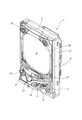
図1に示すように、パチンコ遊技機1は、木製の外枠2の前面に矩形状の前面枠3を開閉可能に取り付け、その前面枠3の裏面に取り付けられている遊技盤収納フレーム(図示せず)内に遊技盤4が装着された構成からなる。遊技盤4は、図2に示す遊技領域40を前面に臨ませた状態で装着され、図1に示すようにこの遊技領域40の前側に透明ガラスを支持したガラス扉枠5が設けられている。なお、上記遊技領域40は、遊技盤4の面上に配設された球誘導レール6(図2参照)で囲まれた領域からなるものである。   As shown in FIG. 1, a pachinko gaming machine 1 has a rectangular front frame 3 attached to the front surface of a wooden outer frame 2 so that it can be opened and closed, and a game board storage frame (see FIG. 1) attached to the back surface of the front frame 3. (Not shown) in which the game board 4 is mounted. The game board 4 is mounted with the game area 40 shown in FIG. 2 facing the front, and a glass door frame 5 supporting transparent glass is provided on the front side of the game area 40 as shown in FIG. . The game area 40 is an area surrounded by a ball guide rail 6 (see FIG. 2) disposed on the surface of the game board 4.

一方、パチンコ遊技機1は、図1に示すように、ガラス扉枠5の下側に前面操作パネル7が配設され、その前面操作パネル7には上受け皿ユニット8が設けられ、この上受け皿ユニット8には、排出された遊技球を貯留する上受け皿9が一体形成されている。また、この前面操作パネル7には、球貸しボタン11及びプリペイドカード排出ボタン12(カード返却ボタン12)が設けられている。そして、上受け皿9の上皿表面部分には、内蔵ランプ(図示せず)点灯時に押下することにより演出効果を変化させることができる押しボタン式の演出ボタン装置13が設けられている。また、この上受け皿9には、当該上受け皿9に貯留された遊技球を下方に抜くための球抜きボタン14が設けられている。   On the other hand, as shown in FIG. 1, the pachinko gaming machine 1 is provided with a front operation panel 7 below the glass door frame 5, and the front operation panel 7 is provided with an upper tray unit 8. The unit 8 is integrally formed with an upper tray 9 for storing discharged game balls. Further, the front operation panel 7 is provided with a ball lending button 11 and a prepaid card discharge button 12 (card return button 12). A push button type effect button device 13 that can change the effect by pressing when a built-in lamp (not shown) is lit is provided on the upper plate surface portion of the upper tray 9. Further, the upper tray 9 is provided with a ball removal button 14 for pulling downward the game balls stored in the upper tray 9.

また一方、図1に示すように、前面操作パネル7の右端部側には、発射ユニットを作動させるための発射ハンドル15が設けられ、前面枠3の上部両側面側には、BGM(Background music)あるいは効果音を発するスピーカ16が設けられている。そして、上記前面枠3の周枠には、LEDランプ等の装飾ランプが配設されている。   On the other hand, as shown in FIG. 1, a launch handle 15 for operating the launch unit is provided on the right end side of the front operation panel 7, and BGM (Background music) is provided on both upper side surfaces of the front frame 3. ) Or a speaker 16 that emits sound effects. A decorative lamp such as an LED lamp is disposed on the peripheral frame of the front frame 3.

他方、上記遊技盤4の遊技領域40には、図2に示すように、略中央部にLCD(Liquid Crystal Display)等からなる液晶表示装置41が配設されている。この液晶表示装置41は、表示エリアを左、中、右の3つのエリアに分割し、独立して数字やキャラクタあるいは図柄(装飾図柄)の変動表示が可能なものである。   On the other hand, in the game area 40 of the game board 4, as shown in FIG. 2, a liquid crystal display device 41 made up of an LCD (Liquid Crystal Display) or the like is disposed at a substantially central portion. The liquid crystal display device 41 divides a display area into three areas, left, middle, and right, and can independently display a variable number, character, or design (decorative design).

一方、液晶表示装置41の真下には、特別図柄始動口42が配設され、その内部には入賞球を検知する特別図柄始動口スイッチ42a(図3参照)が設けられている。そして、この特別図柄始動口42の右側には、大入賞口43が配設され、その内部には入賞球を検知する大入賞口スイッチ43a(図3参照)が設けられている。   On the other hand, a special symbol starting port 42 is disposed directly below the liquid crystal display device 41, and a special symbol starting port switch 42a (see FIG. 3) for detecting a winning ball is provided therein. A special winning opening 43 is provided on the right side of the special symbol starting opening 42, and a large winning opening switch 43a (see FIG. 3) for detecting a winning ball is provided therein.

また一方、上記液晶表示装置41の右上部にはゲートからなる普通図柄始動口44が配設され、その内部には、遊技球の通過を検知する普通図柄始動口スイッチ44a(図3参照)が設けられている。また、上記大入賞口43の右側には、第1の一般入賞口45が配設され、その内部には、遊技球の通過を検知する第1の一般入賞口スイッチ45a(図3参照)が設けられている。さらに、特別図柄始動口42の左側には、複数の第2の一般入賞口46(図示では、3つ)が夫々配設され、その内部には、夫々、遊技球の通過を検知する第2の一般入賞口スイッチ46a(図3参照)が設けられている。   On the other hand, a normal symbol start port 44 consisting of a gate is disposed in the upper right part of the liquid crystal display device 41, and a normal symbol start port switch 44a (see FIG. 3) for detecting the passage of a game ball is provided therein. Is provided. Further, a first general winning opening 45 is provided on the right side of the big winning opening 43, and a first general winning opening switch 45a (see FIG. 3) for detecting the passage of a game ball is provided in the first general winning opening 45. Is provided. In addition, a plurality of second general winning ports 46 (three in the figure) are respectively arranged on the left side of the special symbol starting port 42, and a second one for detecting the passage of the game ball in each of them. The general winning opening switch 46a (see FIG. 3) is provided.

また、上記遊技盤4の遊技領域40の右下周縁部には、7セグメントを3桁に並べて構成される特別図柄表示装置47と、2個のLEDからなる普通図柄表示装置48が設けられている。そしてさらに、上記遊技盤4の遊技領域40には、図示はしないが複数の遊技釘が配設され、遊技球の落下方向変換部材としての風車49が配設されている。   Further, a special symbol display device 47 configured by arranging seven segments in three digits and a normal symbol display device 48 composed of two LEDs are provided at the lower right peripheral edge of the game area 40 of the game board 4. Yes. Further, although not shown, a plurality of game nails are arranged in the game area 40 of the game board 4 and a windmill 49 as a game ball dropping direction changing member is arranged.

さらに、上記遊技盤4の遊技領域における各始動口42,44及び各入賞口43,45,46には、磁気センサ、又は、電波センサ、あるいは、振動センサが設けられており、遊技者が強力な磁石、又は、電波、あるいは、振動によって、遊技に対する不正行為を実行した場合、その不正行為を検知できるようになっている。なお、この磁気センサ、又は、電波センサ、あるいは、振動センサは、不正検知基板50(図3参照)に搭載されている。   Furthermore, each start opening 42, 44 and each winning opening 43, 45, 46 in the game area of the game board 4 is provided with a magnetic sensor, a radio wave sensor, or a vibration sensor. When an illegal act against a game is executed by a simple magnet, radio wave, or vibration, the illegal act can be detected. This magnetic sensor, radio wave sensor, or vibration sensor is mounted on the fraud detection substrate 50 (see FIG. 3).

次に、上記のような外観構成からなるパチンコ遊技機1内に設けられる遊技の進行状況に応じて電子制御を行う制御装置を、図3を用いて説明する。この制御装置は、図3に示すように、遊技動作全般の制御を司る主制御基板60と、その主制御基板60からの払出制御コマンドPAY_CMDに基づいて遊技球を払出す払出制御基板70と、画像と光と音についての制御を行うサブ制御基板80とで主に構成されている。なお、サブ制御基板80は、図3に示すように、演出制御基板90と、装飾ランプ基板100と、液晶制御基板120とで構成されている。   Next, a control device that performs electronic control according to the progress of the game provided in the pachinko gaming machine 1 having the above-described external configuration will be described with reference to FIG. As shown in FIG. 3, the control device includes a main control board 60 that controls overall game operations, a payout control board 70 that pays out game balls based on payout control commands PAY_CMD from the main control board 60, It is mainly composed of an image, a sub-control board 80 that controls light and sound. As shown in FIG. 3, the sub control board 80 includes an effect control board 90, a decorative lamp board 100, and a liquid crystal control board 120.

主制御基板60は、主制御CPU600と、一連の遊技制御手順を記述した遊技プログラム等を格納した主制御ROM601と、作業領域やバッファメモリ等として機能する主制御RAM602とで構成されたワンチップマイコンを搭載している。   The main control board 60 is a one-chip microcomputer comprising a main control CPU 600, a main control ROM 601 storing a game program describing a series of game control procedures, and a main control RAM 602 functioning as a work area, a buffer memory, etc. It is equipped with.

また、主制御基板60には、後述する遊技動作停止フラグGSFをOFFにセットできる、すなわち、停止した遊技動作を再開させることができる遊技動作停止解除スイッチ650が設けられている。なお、この遊技動作停止解除スイッチ650は、係員が操作できるようになっている。   Further, the main control board 60 is provided with a game operation stop release switch 650 that can set a game operation stop flag GSF, which will be described later, to OFF, that is, can restart a stopped game operation. The game operation stop release switch 650 can be operated by a staff member.

一方、このように構成される主制御基板60には、払出モータMを制御して遊技球を払出す払出制御基板70が接続されている。そしてさらには、特別図柄始動口42への入賞を検知する特別図柄始動口スイッチ42aと、普通図柄始動口44の通過を検知する普通図柄始動口スイッチ44aと、第1の一般入賞口45への入賞を検知する第1の一般入賞口スイッチ45aと、第2の一般入賞口46への入賞を検知する第2の一般入賞口スイッチ46aと、遊技者の不正行為を検知する不正検知基板50が接続されている。また、主制御基板60には、特別図柄表示装置47と、普通図柄表示装置48と、主制御基板60における各種情報を遊技機外部に出力するための各外部端子を備えた外部端子基板110が接続されている。   On the other hand, a payout control board 70 that controls the payout motor M to pay out the game ball is connected to the main control board 60 configured as described above. Further, a special symbol start port 42a for detecting a winning in the special symbol start port 42, a normal symbol start port switch 44a for detecting the passage of the normal symbol start port 44, and a first general winning port 45 are provided. A first general winning opening switch 45a for detecting a winning, a second general winning opening switch 46a for detecting a winning to the second general winning opening 46, and a fraud detection board 50 for detecting an illegal act of a player. It is connected. Also, the main control board 60 includes a special symbol display device 47, a normal symbol display device 48, and an external terminal board 110 having external terminals for outputting various information in the main control board 60 to the outside of the gaming machine. It is connected.

このように構成される主制御基板60は、特別図柄始動口スイッチ42aや普通図柄始動口スイッチ44aからの信号を受信すると、遊技者に有利な特別遊技状態を発生させるか(いわゆる「当たり」)、あるいは、遊技者に有利な特別遊技状態を発生させないか(いわゆる「ハズレ」)の抽選を行い、その抽選結果である当否情報に応じて特別図柄の変動パターンや停止図柄あるいは普通図柄の表示内容を決定し、その決定した情報を特別図柄表示装置47又は普通図柄表示装置48に送信する。これにより、特別図柄表示装置47又は普通図柄表示装置48に抽選結果が表示されることとなる。そしてさらに、主制御基板60は、その決定した情報を含む演出制御コマンドDI_CMDを生成し、演出制御基板90に送信する。なお、主制御基板60が、第1の一般入賞口スイッチ45a、第2の一般入賞口スイッチ46a、大入賞口スイッチ43aからの信号を受信した場合は、遊技者に幾らの遊技球を払い出すかを決定し、その決定した情報(払出制御コマンドPAY_CMD)を払出制御基板70に送信することで、払出制御基板70が遊技者に遊技球を払出すこととなる。   When the main control board 60 configured in this way receives a signal from the special symbol start port switch 42a or the normal symbol start port switch 44a, does the main control board 60 generate a special gaming state advantageous to the player (so-called "winning")? Or, a lottery of whether or not a special gaming state advantageous to the player is generated (so-called “losing”) is performed, and the variation pattern of the special symbol, the display pattern of the stopped symbol or the normal symbol is displayed according to the success / failure information which is the lottery result And the determined information is transmitted to the special symbol display device 47 or the normal symbol display device 48. Thereby, the lottery result is displayed on the special symbol display device 47 or the normal symbol display device 48. Further, the main control board 60 generates an effect control command DI_CMD including the determined information and transmits it to the effect control board 90. When the main control board 60 receives signals from the first general winning opening switch 45a, the second general winning opening switch 46a, and the big winning opening switch 43a, it pays out some game balls to the player. The payout control board 70 pays out the game ball to the player by transmitting the determined information (payout control command PAY_CMD) to the payout control board 70.

また、主制御基板60は、不正検知基板50に搭載されている磁気センサ、又は、電波センサ、あるいは、振動センサにて遊技者の不正行為を検知した不正行為検知信号FDFを受信すると、遊技動作の進行を停止し、その停止した情報を含む演出制御コマンドDI_CMDを生成し、演出制御基板90に送信する。さらに、主制御基板60は、上記説明した遊技情報を外部端子基板110に送信し、外部端子基板110は、その情報を、遊技場の遊技島管理に使用されるホールコンピュータHCに送信する。これにより、遊技場の管理者は、遊技機がどのような状態かを把握できるようになる。   Further, when the main control board 60 receives the fraud detection signal FDF in which the fraud detection of the player is detected by the magnetic sensor, the radio wave sensor, or the vibration sensor mounted on the fraud detection board 50, the game operation The production control command DI_CMD including the stopped information is generated and transmitted to the production control board 90. Further, the main control board 60 transmits the game information described above to the external terminal board 110, and the external terminal board 110 transmits the information to the hall computer HC used for game island management of the game hall. Thereby, the manager of the game hall can grasp the state of the gaming machine.

一方、上記払出制御基板70には、図示はしていないが、CPU,ROM,RAMとで構成されたワンチップマイコンを搭載している。そして、そのような払出制御基板70には、遊技者の操作に応答して遊技球を発射させる発射制御基板71が接続されており、この発射制御基板71に対して、当該発射制御基板71の動作を開始又は停止させる発射制御信号を送信する処理を行う。またさらに、払出制御基板70には、外部端子基板110が接続されており、ガラス扉枠5(図2参照)が開放されたか否かの信号が、外部端子基板110に送信されるようになっている。そして、外部端子基板110は、これを受けて、当該情報を、遊技場の遊技島管理に使用されるホールコンピュータHCに送信する。これにより、遊技場の管理者は、ガラス扉枠5が開放されたか否かを即座に判断することができる。   On the other hand, on the payout control board 70, although not shown, a one-chip microcomputer composed of a CPU, a ROM, and a RAM is mounted. The payout control board 70 is connected to a launch control board 71 for launching a game ball in response to the player's operation. The launch control board 71 is connected to the launch control board 71. A process of transmitting a firing control signal for starting or stopping the operation is performed. In addition, an external terminal board 110 is connected to the dispensing control board 70, and a signal indicating whether or not the glass door frame 5 (see FIG. 2) has been opened is transmitted to the external terminal board 110. ing. And the external terminal board 110 receives this, and transmits the said information to the hall computer HC used for the game island management of a game arcade. Thereby, the manager of the game hall can immediately determine whether or not the glass door frame 5 has been opened.

他方、演出制御基板90は、上記主制御基板60からの演出制御コマンドDI_CMDを受けて各種演出を実行制御する演出制御CPU900と、演出制御手順を記述した制御プログラム等が格納されている演出制御ROM901と、作業領域やバッファメモリ等として機能する演出制御RAM902とで構成されている。そしてさらに、演出制御基板90は、所望のBGMや効果音を生成する音LSI903と、BGMや効果音等の音データ等が予め格納されている音ROM904とが搭載されている。   On the other hand, the effect control board 90 receives an effect control command DI_CMD from the main control board 60 and executes an effect control CPU 900 that executes and controls various effects, and an effect control ROM 901 in which a control program describing the effect control procedure is stored. And an effect control RAM 902 that functions as a work area, a buffer memory, and the like. Further, the effect control board 90 is mounted with a sound LSI 903 for generating desired BGM and sound effects, and a sound ROM 904 in which sound data such as BGM and sound effects are stored in advance.

このように構成される演出制御基板90には、ランプ演出効果を現出するLEDランプ等の装飾ランプが搭載されている装飾ランプ基板100が接続され、さらに、内蔵されているランプ(図示せず)点灯時に遊技者が押下することにより演出効果を変化させることができる押しボタン式の演出ボタン装置13が接続され、BGMや効果音等を発するスピーカ16が接続されている。そしてさらに、演出制御基板90には、液晶表示装置41を制御する液晶制御基板120が接続されている。   The effect control board 90 configured as described above is connected to a decorative lamp board 100 on which a decorative lamp such as an LED lamp that exhibits a lamp effect is mounted, and further includes a built-in lamp (not shown). ) A push button type effect button device 13 that can change the effect by pressing the player when it is lit is connected, and a speaker 16 that emits BGM, sound effects, etc. is connected. Furthermore, a liquid crystal control board 120 that controls the liquid crystal display device 41 is connected to the effect control board 90.

かくして、このように構成される演出制御基板90は、主制御基板60より送信される大当たり抽選結果(大当たりかハズレの別)に基づく特別図柄変動パターン、現在の遊技状態、作動保留球数、抽選結果に基づき停止させる装飾図柄等に必要となる基本情報を含んだ演出制御コマンドDI_CMDを演出制御CPU900にて受信する。そして、演出制御CPU900は、受信した演出制御コマンドDI_CMDに対応した演出パターンを、演出制御ROM901内に予め格納しておいた多数の演出パターンの中から抽選により決定し、その決定した演出パターンを実行指示する制御信号を演出制御RAM902内に一時的に格納する。   Thus, the production control board 90 configured as described above has a special symbol variation pattern based on the jackpot lottery result (whether it is a jackpot or lose) transmitted from the main control board 60, the current game state, the number of suspended balls, the lottery. The effect control CPU 900 receives an effect control command DI_CMD including basic information necessary for the decorative design to be stopped based on the result. Then, the effect control CPU 900 determines an effect pattern corresponding to the received effect control command DI_CMD by lottery from a number of effect patterns stored in advance in the effect control ROM 901, and executes the determined effect pattern. The control signal to be instructed is temporarily stored in the effect control RAM 902.

演出制御CPU900は、演出制御RAM902に格納しておいた演出パターンを実行指示する制御信号のうち、音に関する制御信号を音LSI903に送信する。これを受けて音LSI903は、当該制御信号に対応する音データを音ROM904より読み出し、スピーカ16に出力する。これにより、スピーカ16より上記決定された演出パターンに対応したBGMや効果音が発せられることとなる。   The effect control CPU 900 transmits a control signal related to sound to the sound LSI 903 among the control signals for instructing execution of the effect pattern stored in the effect control RAM 902. In response to this, the sound LSI 903 reads the sound data corresponding to the control signal from the sound ROM 904 and outputs it to the speaker 16. Thereby, BGM and sound effects corresponding to the determined effect pattern are emitted from the speaker 16.

また演出制御CPU900は、演出制御RAM902に格納しておいた演出パターンを実行指示する制御信号のうち、光に関する制御信号を装飾ランプ基板100に送信する。これにより、装飾ランプ基板100が、ランプ演出効果を現出するLEDランプ等の装飾ランプを点灯又は消灯する制御を行うため、上記決定された演出パターンに対応したランプ演出が実行されることとなる。   In addition, the effect control CPU 900 transmits a control signal related to light to the decorative lamp substrate 100 among the control signals for instructing execution of the effect pattern stored in the effect control RAM 902. As a result, the decorative lamp substrate 100 performs control to turn on or off a decorative lamp such as an LED lamp that exhibits a lamp effect, and thus the lamp effect corresponding to the determined effect pattern is executed. .

そして演出制御CPU900は、演出制御RAM902に格納しておいた演出パターンを実行指示する制御信号のうち、画像に関する制御信号(液晶制御コマンドLC_CMD)を液晶制御基板120に送信する。これにより、液晶制御基板120が、当該液晶制御コマンドLC_CMDに基づく画像を表示させるように液晶表示装置41を制御することにより、上記決定された演出パターンに対応した画像が液晶表示装置41に表示されることとなる。なお、液晶制御基板120には演出内容に沿った画像を表示するための種々の画像データが記憶されており、さらに、演出出力全般の制御を担うVDP(Video Display Processor)が搭載されている。   Then, the effect control CPU 900 transmits a control signal (liquid crystal control command LC_CMD) related to the image to the liquid crystal control board 120 among the control signals for instructing execution of the effect pattern stored in the effect control RAM 902. Thereby, the liquid crystal control board 120 controls the liquid crystal display device 41 to display an image based on the liquid crystal control command LC_CMD, whereby an image corresponding to the determined effect pattern is displayed on the liquid crystal display device 41. The Rukoto. The liquid crystal control board 120 stores various image data for displaying an image in accordance with the contents of the effect, and further includes a VDP (Video Display Processor) that controls the overall effect output.

ところで、上記説明した各基板への電源供給は、電源基板130(図3参照)より供給されており、この電源基板130は、図3に示すように、電圧生成部1300と、電圧監視部1301と、システムリセット生成部1302とを含んで構成されている。この電圧生成部1300は、遊技店に設置された図示しない変圧トランスから供給される外部電源である交流電圧AC24Vを受けて複数種類の直流電圧を生成するものである。そして、この生成された直流電圧が各基板へ供給されることとなる。なお、主制御基板60には、後述するバックアップ処理を行うにあたり、バックアップ電源が供給されている。   By the way, the power supply to each substrate described above is supplied from a power supply board 130 (see FIG. 3). As shown in FIG. 3, the power supply board 130 includes a voltage generation unit 1300 and a voltage monitoring unit 1301. And a system reset generation unit 1302. This voltage generator 1300 generates a plurality of types of DC voltages in response to an AC voltage AC24V, which is an external power source supplied from a transformer (not shown) installed in the amusement store. Then, the generated DC voltage is supplied to each substrate. Note that backup power is supplied to the main control board 60 when performing backup processing to be described later.

一方、電圧監視部1301は、上記交流電圧AC24Vの電圧を監視するもので、この電圧が遮断されたり、停電が発生したりして電圧異常を検知した場合に電圧異常信号ALARMを主制御基板60に出力するものである。なお、この電圧異常信号ALARMは、電圧異常時には「L」レベルの信号を出力し、正常時には「H」レベルの信号を出力する。   On the other hand, the voltage monitoring unit 1301 monitors the voltage of the AC voltage AC24V. When the voltage is interrupted or a power failure occurs and a voltage abnormality is detected, the voltage monitoring signal ALARM is sent to the main control board 60. Is output. The voltage abnormality signal ALARM outputs an “L” level signal when the voltage is abnormal, and outputs an “H” level signal when it is normal.

また、システムリセット生成部1302は、電源投入時のシステムリセット信号SYS_RSTを生成するもので、その生成したシステムリセット信号SYS_RSTを、主制御基板60,払出制御基板70及びサブ制御基板80に出力するものである。なお、図示では、電源供給ルート、システムリセット信号SYS_RSTの出力ルートは、省略している。   The system reset generation unit 1302 generates a system reset signal SYS_RST at power-on, and outputs the generated system reset signal SYS_RST to the main control board 60, the payout control board 70, and the sub control board 80. It is. In the drawing, the power supply route and the output route of the system reset signal SYS_RST are omitted.

ここで、本発明の特徴部分に係る主制御基板60及びサブ制御基板80の処理内容について図4〜図12も参照してより詳しく説明する。まず、図4〜図9を参照して、主制御基板60の主制御ROM601内に格納されているプログラムの概要を説明する。   Here, the processing contents of the main control board 60 and the sub control board 80 according to the characteristic part of the present invention will be described in more detail with reference to FIGS. First, an outline of a program stored in the main control ROM 601 of the main control board 60 will be described with reference to FIGS.

<主制御:メイン処理>
まず、図4を参照しつつ、メイン処理について説明する。主制御CPU600は、最初に自らを割込み禁止状態に設定すると共に(ステップS1)、主制御CPU600内のレジスタ値等の初期設定を行う(ステップS2)。
<Main control: Main processing>
First, the main process will be described with reference to FIG. The main control CPU 600 first sets itself to an interrupt disabled state (step S1), and initializes register values and the like in the main control CPU 600 (step S2).

続いて、主制御CPU600は、図示しないRAMクリアスイッチのRAMクリア信号を取得し、内部レジスタ(図示せず)内に格納する(ステップS3)。このRAMクリアスイッチは、主制御RAM602の全領域を初期設定するか否かを決定するRAMクリア信号を生成するものであり、主制御基板60又は電源基板130に搭載されており、図1に示す木製の外枠2の背面側に設けられ、係員がON/OFFを操作できるようになっている。   Subsequently, the main control CPU 600 acquires a RAM clear signal of a RAM clear switch (not shown) and stores it in an internal register (not shown) (step S3). This RAM clear switch generates a RAM clear signal for determining whether or not to initialize all the areas of the main control RAM 602, and is mounted on the main control board 60 or the power supply board 130, as shown in FIG. It is provided on the back side of the wooden outer frame 2 so that the clerk can operate ON / OFF.

次いで、主制御CPU600は、電圧異常信号ALARMを2回取得し、その2回取得した電圧異常信号ALARMのレベルが一致するか否かを確認した上で図示しない内部レジスタ内に格納し(ステップS4)、その電圧異常信号ALARMのレベルを確認する。そして電圧異常信号ALARMのレベルが「L」レベルであれば(ステップS5:YES)、ステップS4の処理に戻り、電圧異常信号ALARMのレベルが「H」レベルであれば(ステップS5:NO)、ステップS6の処理に進む。すなわち、主制御CPU600は、電圧異常信号ALARMが正常レベル(すなわち「H」レベル)に変化するまで同一の処理を繰り返す(ステップS4〜S5)。このように、電圧異常信号ALARMを2回取得することで、正確な信号を読み込むことができる。   Next, the main control CPU 600 acquires the voltage abnormality signal ALARM twice, checks whether or not the level of the voltage abnormality signal ALARM acquired twice coincides, and stores it in an internal register (not shown) (step S4). ) Check the level of the voltage abnormality signal ALARM. If the level of the voltage abnormality signal ALARM is “L” level (step S5: YES), the process returns to step S4, and if the level of the voltage abnormality signal ALARM is “H” level (step S5: NO). The process proceeds to step S6. That is, main control CPU 600 repeats the same processing until voltage abnormality signal ALARM changes to a normal level (ie, “H” level) (steps S4 to S5). Thus, an accurate signal can be read by acquiring the voltage abnormality signal ALARM twice.

次いで、主制御CPU600は、主制御RAM602へのデータ書込みを許可する(ステップS6)。このように、電圧異常信号ALARMの正常レベル(正常値)を検知するまで主制御RAM602へのデータ書き込みを禁止することにより、交流電圧AC24Vが安定して供給される前に、不安定な信号が主制御RAM602にアクセスし、主制御RAM602に記憶されているデータを書き換えてしまうという事態を防止することができる。これにより、後述するバックアップ処理の内容が書き換えられてしまうという事態を防止することができる。   Next, the main control CPU 600 permits data writing to the main control RAM 602 (step S6). As described above, by prohibiting data writing to the main control RAM 602 until the normal level (normal value) of the voltage abnormality signal ALARM is detected, an unstable signal is generated before the AC voltage AC24V is stably supplied. A situation where the main control RAM 602 is accessed and data stored in the main control RAM 602 is rewritten can be prevented. Thereby, the situation where the content of the backup process mentioned later is rewritten can be prevented.

次いで、主制御CPU600は、演出制御基板90(図3参照)に液晶表示装置41に待機画面を表示させるような演出制御コマンドDI_CMDを送信する(ステップS7)。これにより、演出制御基板90は、上記演出制御コマンドDI_CMDに基づく液晶制御コマンドLC_CMDを液晶制御基板120に送信し、液晶制御基板120は、その液晶制御コマンドLC_CMDに基づき液晶表示装置41に待機画面を表示させるよう液晶表示装置41を制御する。   Next, the main control CPU 600 transmits an effect control command DI_CMD that causes the liquid crystal display device 41 to display a standby screen on the effect control board 90 (see FIG. 3) (step S7). Thereby, the effect control board 90 transmits the liquid crystal control command LC_CMD based on the effect control command DI_CMD to the liquid crystal control board 120, and the liquid crystal control board 120 displays a standby screen on the liquid crystal display device 41 based on the liquid crystal control command LC_CMD. The liquid crystal display device 41 is controlled to display.

次いで、主制御CPU600は、上記ステップS3にて内部レジスタに格納しておいたRAMクリア信号の内容を判定する(ステップS8)。このRAMクリア信号がON状態であれば(ステップS8:ON)、ステップS13の処理に進み、主制御RAM602の全領域を全てクリアする(ステップS13)。一方、RAMクリア信号がOFF状態であれば(ステップS8:OFF)、バックアップフラグBFLの内容を判定する(ステップS9)。なお、このバックアップフラグBFLとは、後述する図6の電圧監視処理の動作が実行されたか否かを示すデータである。   Next, the main control CPU 600 determines the contents of the RAM clear signal stored in the internal register in step S3 (step S8). If this RAM clear signal is in an ON state (step S8: ON), the process proceeds to step S13, and all areas of the main control RAM 602 are cleared (step S13). On the other hand, if the RAM clear signal is OFF (step S8: OFF), the content of the backup flag BFL is determined (step S9). The backup flag BFL is data indicating whether or not a voltage monitoring process operation of FIG. 6 described later has been executed.

このバックアップフラグBFLがOFF状態(ステップS9:OFF)であれば、後述する図6の電圧監視処理の動作が実行されていないこととなり、主制御CPU600は、主制御RAM602内の全領域を全てクリアする処理を行う(ステップS13)。一方、バックアップフラグBFLがON状態(ステップS9:ON)であれば、後述する図6の電圧監視処理の動作が実行されていることとなるため、主制御CPU600は、チェックサム値を算出するためのチェックサム演算を行う(ステップS10)。なお、チェックサム演算とは、主制御RAM602の作業領域を対象とする8ビット加算演算である。   If the backup flag BFL is in the OFF state (step S9: OFF), the voltage monitoring process operation of FIG. 6 described later is not executed, and the main control CPU 600 clears all the areas in the main control RAM 602. Is performed (step S13). On the other hand, if the backup flag BFL is in the ON state (step S9: ON), the operation of the voltage monitoring process in FIG. 6 to be described later is executed, so the main control CPU 600 calculates the checksum value. The checksum calculation is performed (step S10). The checksum operation is an 8-bit addition operation for the work area of the main control RAM 602.

そして、主制御CPU600は、上記チェックサム値が算出されたら、この演算結果を主制御RAM602内のSUM番地の記憶値と比較する処理を行う(ステップS11)。なお、このSUM番地には、電圧降下時に実行される電圧監視処理(図6参照)において、同じように処理されたチェックサム演算によるチェックサム値が記憶されている(ステップS59)。また、記憶された演算結果は、主制御RAM602内に記憶されている他のデータと共に、上記電源基板130の電圧生成部1300によって生成されたバックアップ電源によって維持されている。   When the checksum value is calculated, the main control CPU 600 performs a process of comparing the calculation result with the stored value at the SUM address in the main control RAM 602 (step S11). Note that the SUM address stores a checksum value by a checksum operation processed in the same manner in the voltage monitoring process (see FIG. 6) executed when the voltage drops (step S59). The stored calculation result is maintained by the backup power source generated by the voltage generation unit 1300 of the power supply board 130 together with other data stored in the main control RAM 602.

このSUM番地の記憶値と上記ステップS10の処理にて算出されたチェックサム値が不一致(ステップS11:NO)であれば、主制御CPU600は、主制御RAM602内の全領域を全てクリアする処理を行う(ステップS13)。そして一致(ステップS11:YES)していれば、主制御CPU600は、主制御RAM602内に記憶されているデータに基づいて電源遮断時の遊技動作に復帰させる処理を行う(ステップS12)。   If the stored value at this SUM address does not match the checksum value calculated in step S10 (step S11: NO), the main control CPU 600 clears all the areas in the main control RAM 602. It performs (step S13). If they match (step S11: YES), the main control CPU 600 performs a process of returning to the gaming operation at the time of power-off based on the data stored in the main control RAM 602 (step S12).

上記処理を終えた後、主制御CPU600は、その内部に設けられている一定周期のパルス出力を作成する機能や時間計測の機能等を有するCTC(Counter Timer Circuit)の設定を行う。すなわち、主制御CPU600は、4ms毎に定期的にタイマ割込みがかかるように上記CTCの時間定数レジスタを設定する(ステップS14)。そして次いで、主制御CPU600は、自身への割込みを禁止状態にセットした状態(ステップS15)で、各種の乱数カウンタの更新処理を行った後(ステップS16)、割込み許可状態に戻して(ステップS17)、ステップS15に戻る処理を行う。   After finishing the above processing, the main control CPU 600 performs setting of a CTC (Counter Timer Circuit) having a function of generating a pulse output of a constant period, a function of time measurement, and the like provided therein. That is, the main control CPU 600 sets the CTC time constant register so that a timer interrupt is periodically generated every 4 ms (step S14). Then, the main control CPU 600 updates various random number counters (step S16) in a state where the interrupt to itself is set to the prohibited state (step S15), and then returns to the interrupt enabled state (step S17). ), Processing to return to step S15.

<主制御:タイマ割込み処理>
続いて、図5を参照して、上述したメイン処理を中断させて、4ms毎に開始されるタイマ割込みプログラムについて説明する。このタイマ割込みが生じると、主制御CPU600は、当該主制御CPU600内のレジスタ群の内容を主制御RAM602のスタック領域に退避させる退避処理を実行し(ステップS20)、その後電圧監視処理を実行する(ステップS21)。なお、この電圧監視処理についての詳細は、後述することとする。
<Main control: Timer interrupt processing>
Next, with reference to FIG. 5, a timer interrupt program started every 4 ms by interrupting the main process described above will be described. When this timer interrupt occurs, the main control CPU 600 executes a saving process for saving the contents of the register group in the main control CPU 600 to the stack area of the main control RAM 602 (step S20), and then executes a voltage monitoring process (step S20). Step S21). Details of the voltage monitoring process will be described later.

次いで、主制御CPU600は、上記電圧監視処理(ステップS21)が終了すると、各入賞口スイッチ43a,45a,46a及び各始動口スイッチ42a,44aを含む各種スイッチ類のON/OFF信号のデータを取得し、主制御RAM602領域にその立ち上がりデータを記憶する(ステップS22)。なお、このスイッチ入力処理についての詳細は、後述することとする。   Next, when the voltage monitoring process (step S21) is completed, the main control CPU 600 obtains ON / OFF signal data of various switches including the winning port switches 43a, 45a, 46a and the starting port switches 42a, 44a. Then, the rising data is stored in the main control RAM 602 area (step S22). Details of the switch input process will be described later.

次いで、主制御CPU600は、各変動表示ゲームに係る乱数を更新する乱数管理処理を実行する(ステップS23)。この乱数管理処理は、当否抽選に使用する普通図柄当り判定用乱数値を更新する処理や、特別図柄の種類を決める特別図柄用乱数値を更新する処理等を実行するものである。   Next, the main control CPU 600 executes a random number management process for updating the random numbers related to each variable display game (step S23). This random number management process executes a process for updating the random number value for determining the normal symbol used for the lottery determination, a process for updating the random number value for the special symbol for determining the type of the special symbol, and the like.

そして続いて、主制御CPU600は、遊技動作停止フラグGSFの内容を判定する(ステップS24)。なお、この遊技動作停止フラグGSFとは、後述する図9のエラー管理処理にて、遊技の不正を検知した際、遊技動作の進行を停止させるためのデータである。   Subsequently, the main control CPU 600 determines the content of the game operation stop flag GSF (step S24). The game operation stop flag GSF is data for stopping the progress of the game operation when an illegal game is detected in an error management process of FIG. 9 described later.

このような遊技動作停止フラグGSFがON状態(ステップS24:YES)であれば、主制御CPU600は、ステップS25〜ステップS32の処理をせずステップS33の処理に進み、OFF状態(ステップS24:NO)であれば、各遊技動作の時間を管理しているタイマのタイマ減算処理を行う(ステップS25)。ここで減算されたタイマは、大入賞口43(図2参照)の開放時間、普通図柄の変動時間、特別図柄の変動時間等の遊技演出時間、不正情報タイマ等を管理するために使用されるものである。   If such a game operation stop flag GSF is in the ON state (step S24: YES), the main control CPU 600 proceeds to the processing in step S33 without performing the processing in steps S25 to S32, and is in the OFF state (step S24: NO). ), A timer subtraction process of a timer managing the time of each game operation is performed (step S25). The timer subtracted here is used to manage the opening time of the special winning opening 43 (see FIG. 2), the game effect time such as the normal symbol fluctuation time, the special symbol fluctuation time, the fraud information timer, and the like. Is.

次いで、主制御CPU600は、賞球管理処理を実行する(ステップS26)。この賞球管理処理は、払出制御基板70に払出し動作を行わせるための払出制御コマンドPAY_CMDを出力している。なお、この賞球管理処理の詳細については、後述することとする。   Next, the main control CPU 600 executes prize ball management processing (step S26). In this prize ball management process, a payout control command PAY_CMD for causing the payout control board 70 to perform a payout operation is output. The details of the prize ball management process will be described later.

次いで、主制御CPU600は、普通図柄処理を実行する(ステップS27)。この普通図柄処理は、普通図柄の当否抽選を実行し、その抽選結果に基づいて普通図柄の変動パターンや普通図柄の停止表示状態を決定したりするものである。   Next, the main control CPU 600 executes normal symbol processing (step S27). In this normal symbol processing, a normal symbol winning / losing lottery is executed, and the variation pattern of the normal symbol and the stop display state of the normal symbol are determined based on the lottery result.

次いで、主制御CPU600は、特別図柄処理を実行する(ステップS28)。この特別図柄処理では、特別図柄の当否抽選を実行し、その抽選の結果に基づいて特別図柄の変動パターンや特別図柄の停止表示態様(停止特別図柄)を決定する。   Next, the main control CPU 600 executes special symbol processing (step S28). In this special symbol process, whether or not a special symbol is selected is determined, and a variation pattern of the special symbol and a stop display mode of the special symbol (stop special symbol) are determined based on the result of the lottery.

次いで、主制御CPU600は、LED管理処理を実行する(ステップS29)。このLED管理処理は、処理の進行状態に応じて、特別図柄表示装置47や普通図柄表示装置48への出力データを作成したり、当該データに基づく制御信号を出力したりする処理である。   Next, the main control CPU 600 executes LED management processing (step S29). This LED management process is a process of creating output data to the special symbol display device 47 or the normal symbol display device 48 or outputting a control signal based on the data according to the progress of the process.

次いで、主制御CPU600は、大入賞口43(図2参照)等の開閉動作を実現するソレノイドの駆動処理を実行する(ステップS30)。   Next, the main control CPU 600 executes a solenoid driving process for realizing an opening / closing operation of the special prize opening 43 (see FIG. 2) (step S30).

次いで、主制御CPU600は、外部端子管理処理を実行する(ステップS31)。この外部端子管理処理では、外部端子基板110(図3参照)を介して、遊技場の遊技島管理に使用されるホールコンピュータHCに、当り遊技中、当りの発生回数、特別図柄の変動回数、入賞口への入賞球検出情報など、所定の遊技情報が出力される。   Next, the main control CPU 600 executes an external terminal management process (step S31). In this external terminal management process, through the external terminal board 110 (see FIG. 3), the hall computer HC used for game island management of the amusement hall is subjected to a hit game, the number of hits, the number of changes in special symbols, Predetermined game information such as winning ball detection information for a winning opening is output.

そして続いて、主制御CPU600は、エラー管理処理を行う(ステップS32)。このエラー管理処理は、不正検知基板50(図3参照)に搭載されている磁気センサ、又は、電波センサ、あるいは、振動センサにて遊技者の不正行為を検知したか否かを確認し、不正行為を検知していれば、遊技動作停止フラグGSFをONにセットするものである。なお、このエラー管理処理についての詳細は、後述することとする   Subsequently, the main control CPU 600 performs error management processing (step S32). This error management process is performed by confirming whether a player's fraud is detected by a magnetic sensor, a radio wave sensor, or a vibration sensor mounted on the fraud detection board 50 (see FIG. 3). If an action is detected, the game operation stop flag GSF is set to ON. Details of the error management process will be described later.

この処理を終えた後、又は、遊技動作停止フラグGSFがON状態(ステップS24:YES)であれば、主制御CPU600は、割込み許可状態に戻す処理を行い(ステップS33)、主制御RAM602のスタック領域に退避させておいたレジスタの内容を復帰させタイマ割込みを終える(ステップS34)。これにより、割込み処理ルーチンからメイン処理(図4参照)に戻ることとなる。   After this processing is completed, or if the game operation stop flag GSF is in the ON state (step S24: YES), the main control CPU 600 performs processing for returning to the interrupt permission state (step S33), and the main control RAM 602 stacks. The contents of the register saved in the area are restored, and the timer interrupt is finished (step S34). As a result, the interrupt processing routine returns to the main processing (see FIG. 4).

<主制御:電圧監視処理>
次に、図6を参照して、上記電圧監視処理(図5のステップS21)について詳細に説明する。電圧監視処理は、先ず、電源基板130から出力された電圧異常信号ALARMを2回取得し、その2回取得した電圧異常信号ALARMのレベルが一致するか否かを確認した上で主制御CPU600の内部レジスタ内に格納し(ステップS50)、その電圧異常信号ALARMのレベルを確認する。そして電圧異常信号ALARMのレベルが「H」レベルであれば(ステップS51:NO)、ステップS52の処理に進み、電圧異常信号ALARMのレベルが「L」レベルであれば(ステップS51:YES)、ステップS53の処理に進む。
<Main control: Voltage monitoring process>
Next, the voltage monitoring process (step S21 in FIG. 5) will be described in detail with reference to FIG. In the voltage monitoring process, first, the voltage abnormality signal ALARM output from the power supply board 130 is acquired twice, and it is confirmed whether or not the level of the voltage abnormality signal ALARM acquired twice coincides with the main control CPU 600. The data is stored in the internal register (step S50), and the level of the voltage abnormality signal ALARM is confirmed. If the level of the voltage abnormality signal ALARM is “H” level (step S51: NO), the process proceeds to step S52, and if the level of the voltage abnormality signal ALARM is “L” level (step S51: YES). The process proceeds to step S53.

電圧異常信号ALARMのレベルが「H」レベルであれば(ステップS51:NO)、主制御CPU600は、バックアップフラグBFLをOFFにセットし(ステップS52)、電圧異常確認カウンタをゼロにクリアし(ステップS54)、図5に示すステップS22の処理に進む。   If the level of voltage abnormality signal ALARM is “H” level (step S51: NO), main control CPU 600 sets backup flag BFL to OFF (step S52) and clears the voltage abnormality confirmation counter to zero (step S52). S54), the process proceeds to step S22 shown in FIG.

一方、電圧異常信号ALARMのレベルが「L」レベルであれば(ステップS51:YES)、主制御CPU600は、電圧異常確認カウンタをインクリメント(+1)し(ステップS53)、電圧異常確認カウンタのカウント値が2以上か否かの確認を行う(ステップS55)。そして、電圧異常確認カウンタのカウント値が2より小さければ(ステップS55:NO)、図5に示すステップS22の処理に進み、電圧異常確認カウンタのカウント値が2以上であれば(ステップS55:YES)、電圧異常確認カウンタをゼロにクリアする処理を行うことでバックアップ処理を開始する(ステップS56)。   On the other hand, if the level of voltage abnormality signal ALARM is “L” level (step S51: YES), main control CPU 600 increments (+1) the voltage abnormality confirmation counter (step S53), and the count value of the voltage abnormality confirmation counter It is confirmed whether or not is 2 or more (step S55). If the count value of the voltage abnormality confirmation counter is smaller than 2 (step S55: NO), the process proceeds to step S22 shown in FIG. 5, and if the count value of the voltage abnormality confirmation counter is 2 or more (step S55: YES). ), The backup process is started by performing a process of clearing the voltage abnormality confirmation counter to zero (step S56).

そして、主制御CPU600は、バックアップ処理を行うにあたり、バックアップフラグBFLをONにセットし(ステップS57)、演出制御基板90に電源が遮断したことを報知する演出制御コマンドDI_CMDを送信する(ステップS58)。続いて、主制御CPU600は、図4に示すメイン処理のステップS10と同一の演算を、同一の作業領域に対して行い、その演算結果を記憶する処理を行うことでバックアップ処理を終了する(ステップS59)。   Then, when performing the backup process, the main control CPU 600 sets the backup flag BFL to ON (step S57), and transmits an effect control command DI_CMD that notifies the effect control board 90 that the power supply has been cut off (step S58). . Subsequently, the main control CPU 600 performs the same calculation as step S10 of the main process shown in FIG. 4 on the same work area, and ends the backup process by performing a process of storing the calculation result (step S10). S59).

そしてその後、主制御CPU600は、主制御RAM602へのデータ書込みを禁止状態に設定する(ステップS60)と共に、全ての出力ポートのデータをクリアする(ステップS61)。そして、主制御CPU600は、CTCに対する設定処理によってタイマ割込みを禁止し(ステップS62)、主制御CPU600が非動作状態になるのを待つ。なお、主制御RAM602には、電源基板130の電圧生成部1300にて生成されたバックアップ電源が供給されているため、主制御RAM602に格納されたバックアップデータは、そのまま維持されることとなる。   After that, the main control CPU 600 sets data writing to the main control RAM 602 in a prohibited state (step S60) and clears data of all output ports (step S61). Then, the main control CPU 600 prohibits timer interruption by setting processing for the CTC (step S62), and waits for the main control CPU 600 to become inoperative. The main control RAM 602 is supplied with the backup power generated by the voltage generation unit 1300 of the power supply board 130, so the backup data stored in the main control RAM 602 is maintained as it is.

<主制御:スイッチ入力処理>
次に、図7を参照して、上記スイッチ入力処理(図5のステップS22)について詳細に説明する。図7に示すように、スイッチ入力処理では、先ず、各入力ポートの入力データを取得する。すなわち、主制御CPU600は、各入賞口スイッチ43a,45a,46a及び各始動口スイッチ42a,44aを含む各種スイッチ類のON/OFF信号のデータを入力ポートより取得し、その取得した各種スイッチ類のON/OFF信号のデータに基づいて各種スイッチ類の立ち上がりデータを作成する。そして、主制御CPU600は、その作成した各種スイッチ類の立ち上がりデータを主制御RAM602領域に格納する(ステップS70)。
<Main control: Switch input processing>
Next, the switch input process (step S22 in FIG. 5) will be described in detail with reference to FIG. As shown in FIG. 7, in the switch input process, first, input data of each input port is acquired. That is, the main control CPU 600 acquires the ON / OFF signal data of various switches including the winning port switches 43a, 45a, 46a and the starting port switches 42a, 44a from the input port, and the acquired various switches. Based on the ON / OFF signal data, rising data of various switches is created. The main control CPU 600 stores the created rising data of the various switches in the main control RAM 602 area (step S70).

次いで、主制御CPU600は、遊技動作停止フラグGSFの内容を判定し(ステップS71)、この遊技動作停止フラグGSFがOFF状態(ステップS71:NO)であれば、主制御CPU600は、ステップS74の処理に進み、ON状態(ステップS71:YES)であれば、主制御CPU600は、遊技動作停止解除スイッチ650がON状態であるか否かを確認する(ステップS72)。OFF状態であれば(ステップS72:NO)、ステップS73〜ステップS76の処理をせず図5に示すステップS23の処理に進む。これは、遊技動作停止時に、各入賞口スイッチ43a,45a,46a及び各始動口スイッチ42a,44aにて入球(賞球)を検知しても、遊技球を払出さず、入球(賞球)自体を無効にするためである。   Next, the main control CPU 600 determines the content of the game operation stop flag GSF (step S71). If the game operation stop flag GSF is in the OFF state (step S71: NO), the main control CPU 600 performs the process of step S74. If it is ON state (step S71: YES), the main control CPU 600 confirms whether or not the game operation stop release switch 650 is in the ON state (step S72). If it is in the OFF state (step S72: NO), the process proceeds to the process of step S23 shown in FIG. 5 without performing the process of steps S73 to S76. This is because, when the game operation is stopped, even if a winning ball (award ball) is detected by each winning port switch 43a, 45a, 46a and each start port switch 42a, 44a, the gaming ball is not paid out and the winning ball (award) This is to invalidate the sphere itself.

一方、ON状態であれば(ステップ72:YES)、遊技動作停止フラグGSFをOFFにセットし、演出制御基板90(図3参照)に遊技動作停止復帰を知らせる演出制御コマンドDI_CMDを送信し(ステップS73)、ステップS74の処理に進む。なお、演出制御基板90は、この演出制御コマンドDI_CMDを受けて、例えば、電源供給遮断時のバックアップ復帰とは異なる演出パターンとなるようにLEDランプ等の装飾ランプを夫々点灯又は消灯させるか、或いは、液晶表示装置41に遊技動作停止状態から復帰した旨を表示させるように制御する。このように、演出制御基板90は、電源供給遮断時のバックアップ復帰とは異なり、遊技動作停止状態から復帰したことが明確になるように、装飾ランプ等を用いて外部に報知するようにする。   On the other hand, if it is in the ON state (step 72: YES), the game operation stop flag GSF is set to OFF, and the effect control command DI_CMD informing the effect control board 90 (see FIG. 3) of the game operation stop return is transmitted (step S73), the process proceeds to step S74. The production control board 90 receives the production control command DI_CMD and turns on or off the decorative lamps such as LED lamps so that the production pattern is different from the backup restoration at the time of power supply interruption, for example. Then, the liquid crystal display device 41 is controlled to display that it has returned from the gaming operation stop state. Thus, unlike the backup recovery at the time of power supply interruption, the effect control board 90 notifies the outside using a decorative lamp or the like so that it is clear that the game operation has been stopped.

上記処理を終えた後、主制御CPU600は、不正入賞があったか否かを確認、すなわち、大入賞口43(図2参照)等が閉止していなければならない遊技状態にもかかわらず開放されているか否かを確認し、開放されていれば、不正入賞であると判断し、上記主制御RAM602領域に格納しておいた各種スイッチ類の立ち上がりデータのうち不正入賞であると判断したデータに関し無効にする処理を行う(ステップS74)。   After finishing the above processing, the main control CPU 600 confirms whether or not there has been an illegal prize, that is, whether the big prize opening 43 (see FIG. 2) or the like is open despite the gaming state that must be closed. If it is open, it is determined that the winning is illegal, and the data determined to be illegal winning among the rising data of various switches stored in the main control RAM 602 area is invalidated. Is performed (step S74).

次いで、主制御CPU600は、主制御RAM602領域に格納しておいた各種スイッチ類の立ち上がりデータを取得し、これら立ち上がりデータが全てOFF状態(ステップS75:NO)であれば、図5に示すステップS23の処理に進み、これら立ち上がりデータのうちいずれか一つのデータがON状態(ステップS75:YES)であれば、ステップS76の処理に進む。   Next, the main control CPU 600 acquires rising data of various switches stored in the main control RAM 602 area, and if these rising data are all in the OFF state (step S75: NO), step S23 shown in FIG. If any one of the rising data is in the ON state (step S75: YES), the process proceeds to step S76.

このステップS76の処理にて、主制御CPU600は、賞球数毎に対応した入賞カウンタをインクリメント(+1)する処理を行う(ステップS76)。すなわち、主制御RAM602には、特別図柄入賞カウンタSD_CNT,第1の一般入賞カウンタGP_CNT1,第2の一般入賞カウンタGP_CNT2,大入賞カウンタLP_CNTが格納されており、特別図柄始動口スイッチ42aにて入球(賞球)を検知した場合は、主制御CPU600は、その検知した賞球数分、特別図柄入賞カウンタSD_CNTをインクリメント(+1)する処理を行う。また、第1の一般入賞口スイッチ45aにて入球(賞球)を検知した場合は、主制御CPU600は、その検知した賞球数分、第1の一般入賞カウンタGP_CNT1をインクリメント(+1)する処理を行う。さらに、第2の一般入賞口スイッチ46aにて入球(賞球)を検知した場合は、主制御CPU600は、その検知した賞球数分、第2の一般入賞カウンタGP_CNT2をインクリメント(+1)する処理を行う。そして、大入賞口スイッチ43aにて入球(賞球)を検知した場合は、主制御CPU600は、その検知した賞球数分、大入賞カウンタLP_CNTをインクリメント(+1)する処理を行う。   In the process of step S76, the main control CPU 600 performs a process of incrementing (+1) a winning counter corresponding to each prize ball number (step S76). That is, the main control RAM 602 stores the special symbol winning counter SD_CNT, the first general winning counter GP_CNT1, the second general winning counter GP_CNT2, and the big winning counter LP_CNT, and the special symbol start opening switch 42a enters the ball. When (prize ball) is detected, the main control CPU 600 performs a process of incrementing (+1) the special symbol winning counter SD_CNT by the detected number of prize balls. When the first general winning opening switch 45a detects a winning ball (principal ball), the main control CPU 600 increments (+1) the first general winning counter GP_CNT1 by the detected number of winning balls. Process. Further, when the second general winning opening switch 46a detects a winning ball (principal ball), the main control CPU 600 increments (+1) the second general winning counter GP_CNT2 by the detected number of winning balls. Process. When a winning ball (prize ball) is detected by the special winning opening switch 43a, the main control CPU 600 performs a process of incrementing (+1) the big winning counter LP_CNT by the detected number of winning balls.

このような処理を終えた後、主制御CPU600は、図5に示すステップS23の処理に進む。   After completing such processing, the main control CPU 600 proceeds to the processing of step S23 shown in FIG.

<主制御:賞球管理処理>
次に、図8を参照して、上記賞球管理処理(図5のステップS26)について詳細に説明する。図8に示すように、賞球管理処理では、先ず、入賞カウンタの総数をループカウンタLOOP_CNTにセットする(ステップS80)。すなわち、本実施形態においては、主制御RAM602に格納されている入賞カウンタは、特別図柄入賞カウンタSD_CNT,第1の一般入賞カウンタGP_CNT1,第2の一般入賞カウンタGP_CNT2,大入賞カウンタLP_CNTの4つが格納されているため、ループカウンタLOOP_CNTに4がセットされる。
<Main control: prize ball management processing>
Next, the prize ball management process (step S26 in FIG. 5) will be described in detail with reference to FIG. As shown in FIG. 8, in the winning ball management process, first, the total number of winning counters is set in the loop counter LOOP_CNT (step S80). That is, in the present embodiment, four winning counters stored in the main control RAM 602 are stored: special symbol winning counter SD_CNT, first general winning counter GP_CNT1, second general winning counter GP_CNT2, and big winning counter LP_CNT. Therefore, 4 is set in the loop counter LOOP_CNT.

次いで、主制御CPU600は、入賞カウンタの番号に1をセットする。より詳しく説明すると、本実施形態においては、特別図柄入賞カウンタSD_CNT,第1の一般入賞カウンタGP_CNT1,第2の一般入賞カウンタGP_CNT2,大入賞カウンタLP_CNTの4つの入賞カウンタが存在しているため、それぞれの入賞カウンタに番号が割り当てられることとなる。すなわち、特別図柄入賞カウンタSD_CNTの番号は1、第1の一般入賞カウンタGP_CNT1の番号は2、第2の一般入賞カウンタGP_CNT2の番号は3、大入賞カウンタLP_CNTの番号は4というように番号が割り当てられることとなり、その割り当てられた番号を示す数値がNで、その数値Nに1がセットされる(ステップS81)。   Next, the main control CPU 600 sets 1 to the number of the winning counter. More specifically, in the present embodiment, there are four winning counters, namely the special symbol winning counter SD_CNT, the first general winning counter GP_CNT1, the second general winning counter GP_CNT2, and the big winning counter LP_CNT. A number will be assigned to the winning counter. That is, the number of the special symbol winning counter SD_CNT is assigned as 1, the number of the first general winning counter GP_CNT1 is 2, the number of the second general winning counter GP_CNT2 is 3, and the number of the big winning counter LP_CNT is 4. The numerical value indicating the assigned number is N, and 1 is set to the numerical value N (step S81).

次いで、主制御CPU600は、その数値Nにセットされた番号を確認し、その番号に該当する入賞カウンタの値を確認する(ステップS82)。すなわち、数値Nに1がセットされていた場合は、特別図柄入賞カウンタSD_CNTの値が0か否かを確認し、数値Nに2がセットされていた場合は、第1の一般入賞カウンタGP_CNT1の値が0か否かを確認し、数値Nに3がセットされていた場合は、第2の一般入賞カウンタGP_CNT2の値が0か否かを確認し、数値Nに4がセットされていた場合は、大入賞カウンタLP_CNTの値が0か否かを確認する。   Next, the main control CPU 600 confirms the number set to the numerical value N, and confirms the value of the winning counter corresponding to the number (step S82). That is, when 1 is set to the numerical value N, it is checked whether or not the value of the special symbol winning counter SD_CNT is 0. When the numerical value N is set to 2, the first general winning counter GP_CNT1 is checked. Check if the value is 0 and if the value N is set to 3, if the value of the second general winning counter GP_CNT2 is 0 and if the value N is set to 4 Confirms whether the value of the big prize counter LP_CNT is 0 or not.

そして、入賞カウンタの値が0であれば(ステップS82:=0)、主制御CPU600は、数値Nをインクリメント(+1)する処理を行い(ステップS83)、ループカウンタLOOP_CNTの値を減算(−1)する処理を行う(ステップS84)。そしてその処理によって、ループカウンタLOOP_CNTの値が0(ステップS85:=0)になれば、図5に示すステップS27の処理に進み、0でなければ(ステップS85:≠0)、ステップS82に戻り、ステップS82〜ステップS85の処理を繰り返す。   If the value of the winning counter is 0 (step S82: = 0), the main control CPU 600 performs a process of incrementing (+1) the numerical value N (step S83), and subtracts the value of the loop counter LOOP_CNT (−1). ) Is performed (step S84). If the value of the loop counter LOOP_CNT becomes 0 (step S85: = 0) by the process, the process proceeds to the process of step S27 shown in FIG. 5, and if not 0 (step S85: ≠ 0), the process returns to step S82. , Steps S82 to S85 are repeated.

一方、主制御CPU600は、入賞カウンタの値が0でなければ(ステップS82:≠0)、数値Nに1がセットされていた場合、特別図柄入賞カウンタSD_CNTの値を減算(−1)する処理を行い、数値Nに2がセットされていた場合、第1の一般入賞カウンタGP_CNT1の値を減算(−1)する処理を行い、数値Nに3がセットされていた場合、第2の一般入賞カウンタGP_CNT2の値を減算(−1)する処理を行い、数値Nに4がセットされていた場合、大入賞カウンタLP_CNTの値を減算(−1)する処理を行う(ステップS86)。   On the other hand, if the value of the winning counter is not 0 (step S82: ≠ 0), the main control CPU 600 subtracts (-1) the value of the special symbol winning counter SD_CNT when the numerical value N is set to 1. When the value N is set to 2, the value of the first general winning counter GP_CNT1 is subtracted (-1). When the value N is set to 3, the second general winning award A process of subtracting (-1) the value of the counter GP_CNT2 is performed, and if the value N is set to 4, a process of subtracting (-1) the value of the big prize counter LP_CNT is performed (step S86).

そして、この処理の後、主制御CPU600は、払出個数を指定した払出制御コマンドPAY_CMDを払出制御基板70(図3参照)に送信する。すなわち、上記ステップS86の処理にて、特別図柄入賞カウンタSD_CNTの値を減算した場合は、そのカウンタ値を減算した値、すなわち、1に対応した遊技球(例えば、3個)を払出すよう指定した払出制御コマンドPAY_CMDを払出制御基板70(図3参照)に送信し、第1の一般入賞カウンタGP_CNT1の値を減算した場合は、そのカウンタ値を減算した値、すなわち、1に対応した遊技球(例えば、5個)を払出すよう指定した払出制御コマンドPAY_CMDを払出制御基板70(図3参照)に送信し、第2の一般入賞カウンタGP_CNT2の値を減算した場合は、そのカウンタ値を減算した値、すなわち、1に対応した遊技球(例えば、10個)を払出すよう指定した払出制御コマンドPAY_CMDを払出制御基板70(図3参照)に送信し、大入賞カウンタLP_CNTの値を減算した場合は、そのカウンタ値を減算した値、すなわち、1に対応した遊技球(例えば、15個)を払出すよう指定した払出制御コマンドPAY_CMDを払出制御基板70(図3参照)に送信する(ステップS87)。これにより、払出制御基板70は、当該払出制御コマンドPAY_CMDに基づいて、払出モータMを制御して遊技球を払出すこととなる。   After this processing, the main control CPU 600 transmits a payout control command PAY_CMD specifying the payout number to the payout control board 70 (see FIG. 3). That is, when the value of the special symbol winning counter SD_CNT is subtracted in the process of step S86, a value obtained by subtracting the counter value, that is, a game ball (for example, 3) corresponding to 1 is designated to be paid out. When the paid payout control command PAY_CMD is transmitted to the payout control board 70 (see FIG. 3) and the value of the first general winning counter GP_CNT1 is subtracted, a value obtained by subtracting the counter value, that is, a game ball corresponding to 1 When the payout control command PAY_CMD designated to pay out (for example, 5) is transmitted to the payout control board 70 (see FIG. 3) and the value of the second general winning counter GP_CNT2 is subtracted, the counter value is subtracted. The payout control board 7 outputs the payout control command PAY_CMD designated to pay out the game value corresponding to 1 (for example, 10). (See FIG. 3), when the value of the special prize counter LP_CNT is subtracted, the value obtained by subtracting the counter value, that is, the payout designated to pay out game balls (for example, 15 balls) corresponding to 1 A control command PAY_CMD is transmitted to the payout control board 70 (see FIG. 3) (step S87). Thereby, the payout control board 70 pays out the game ball by controlling the payout motor M based on the payout control command PAY_CMD.

かくして、主制御CPU600は、上記処理を終えた後、図5に示すステップS27の処理に進む。   Thus, after finishing the above process, the main control CPU 600 proceeds to the process of step S27 shown in FIG.

このように、上記詳述した賞球管理処理を参酌すれば明らかなように、1回のタイマ割込み処理(図5参照)において、1回の入賞分しか遊技球を払出さないようにしている。そのため、いずれかの入賞カウンタ(特別図柄入賞カウンタSD_CNT,第1の一般入賞カウンタGP_CNT1,第2の一般入賞カウンタGP_CNT2,大入賞カウンタLP_CNT)がまだ0でない場合は、次のタイマ割込み処理において、1回の入賞分が払出されることとなる。そして、すべての入賞カウンタが0になるまで、タイマ割込み処理毎に、1回の入賞分が払出されていくことになる。   In this way, as apparent from the above-described prize ball management process, in one timer interrupt process (see FIG. 5), the game ball is paid out only for one winning prize. . Therefore, if any of the winning counters (special symbol winning counter SD_CNT, first general winning counter GP_CNT1, second general winning counter GP_CNT2, large winning counter LP_CNT) is not yet 0, in the next timer interrupt process, The winning portion will be paid out. Then, one winning portion is paid out every timer interrupt process until all winning counters become zero.

しかして、主制御CPU600より払出制御コマンドPAY_CMDを払出制御基板70(図3参照)に送信(ステップS87参照)した後、遊技動作停止フラグGSFがON状態になった場合は、払出制御基板70にて、当該払出制御コマンドPAY_CMDに基づいて遊技球を払出す処理を行う。   Thus, after the main control CPU 600 transmits the payout control command PAY_CMD to the payout control board 70 (see FIG. 3) (see step S87), if the game operation stop flag GSF is turned on, the main control CPU 600 sends a payout control board 70 to the payout control board 70. Thus, processing for paying out the game ball is performed based on the payout control command PAY_CMD.

そして、払出制御コマンドPAY_CMDが払出制御基板70に送信される前に、遊技動作停止フラグGSFがON状態になった場合は、図5に示すように、賞球管理処理(ステップS26)は実行されないため、遊技動作停止フラグGSFがON状態になる前に、特別図柄始動口スイッチ42a,第1の一般入賞口スイッチ45a,第2の一般入賞口スイッチ46a,大入賞口スイッチ43aのいずれかにおいて入球(賞球)を検知したもの、すなわち、特別図柄入賞カウンタSD_CNT,第1の一般入賞カウンタGP_CNT1,第2の一般入賞カウンタGP_CNT2,大入賞カウンタLP_CNTのいずれかが0でなく1以上のカウント値を保有しているものについては、その入球(賞球)に関する遊技球の払出しは行わず、図7に示すように遊技動作停止解除スイッチ650(図3参照)がONされ、遊技動作停止フラグGSFがOFF状態(ステップS73)となった後、ステップS26の賞球管理処理にて処理が実行され、遊技球が払出されることとなる。   If the game operation stop flag GSF is turned on before the payout control command PAY_CMD is transmitted to the payout control board 70, the winning ball management process (step S26) is not executed as shown in FIG. Therefore, before the game operation stop flag GSF is turned on, the special symbol start port switch 42a, the first general winning port switch 45a, the second general winning port switch 46a, or the big winning port switch 43a is entered. A detected ball (prize ball), that is, one of the special symbol winning counter SD_CNT, the first general winning counter GP_CNT1, the second general winning counter GP_CNT2, and the big winning counter LP_CNT is not 0 but a count value of 1 or more As shown in FIG. 7, no game balls are paid out for those who have a ball. After the game operation stop release switch 650 (see FIG. 3) is turned ON and the game operation stop flag GSF is turned off (step S73), the process is executed in the prize ball management process in step S26, and the game ball is It will be paid out.

<主制御:エラー管理処理>
次に、図9を参照して、上記エラー管理処理(図5のステップS32)について詳細に説明する。図9に示すように、エラー管理処理では、先ず、不正検知基板50に搭載されている磁気センサ、又は、電波センサ、あるいは、振動センサにて遊技者の不正行為を検知したか否かの信号、すなわち、不正行為検知信号FDFを取得する(ステップS90)。これにより、不正行為検知信号FDFがOFF状態(ステップS91:NO)であれば、主制御CPU600は、遊技者による不正行為はないと判断し、図5に示すステップS33の処理に進む。
<Main control: Error management processing>
Next, the error management process (step S32 in FIG. 5) will be described in detail with reference to FIG. As shown in FIG. 9, in the error management process, first, a signal indicating whether or not a player's cheating is detected by a magnetic sensor, radio wave sensor, or vibration sensor mounted on the cheating detection board 50. That is, the fraud detection signal FDF is acquired (step S90). Thereby, if the cheating detection signal FDF is in the OFF state (step S91: NO), the main control CPU 600 determines that there is no cheating by the player, and proceeds to the process of step S33 shown in FIG.

一方、不正行為検知信号FDFがON状態(ステップS91:YES)であれば、主制御CPU600は、遊技者による不正行為があったと判断し、遊技動作停止フラグGSFをONにセットし(ステップS92)、大入賞口43(図2参照)等の開閉動作を実現するソレノイドの動作を停止させる処理を行う(ステップS93)。これは、ソレノイドを動作状態のままにして遊技動作を停止させてしまうと、ソレノイドが熱を持ってしまい、故障の原因となるためである。   On the other hand, if the cheating detection signal FDF is in the ON state (step S91: YES), the main control CPU 600 determines that there has been cheating by the player, and sets the gaming operation stop flag GSF to ON (step S92). Then, a process for stopping the operation of the solenoid for realizing the opening / closing operation of the special winning opening 43 (see FIG. 2) is performed (step S93). This is because if the game operation is stopped while the solenoid is left in an operating state, the solenoid will have heat, causing a failure.

次いで、主制御CPU600は、出力ポートのデータをクリアする(ステップS94)。ここで、主制御CPU600は、出力ポートのデータをクリアするにあたって、少なくとも、特別図柄表示装置47に送信するデータをクリアする。これにより、主制御基板60にて遊技動作の進行が停止されたことを、遊技者又は遊技場の関係者に明確に報知することができる。なお、その他のデータ(例えば、演出制御基板90への演出制御コマンドDI_CMD等)に関しては、クリアしても良いし、遊技動作の停止後に特段影響を及ぼさないのであればクリアしなくても良い。   Next, the main control CPU 600 clears the output port data (step S94). Here, the main control CPU 600 clears at least the data transmitted to the special symbol display device 47 when clearing the data of the output port. Thereby, it is possible to clearly notify the player or the person concerned at the game hall that the progress of the game operation is stopped on the main control board 60. Note that other data (for example, an effect control command DI_CMD to the effect control board 90) may be cleared, or may not be cleared if there is no particular influence after the game operation is stopped.

次いで、主制御CPU600は、遊技動作が停止した旨の情報を外部端子基板110に送信する(ステップS95)。これにより、外部端子基板110は、その情報をホールコンピュータHCに送信するため、遊技場の管理者は、遊技動作が停止した旨を早期に知ることができる。   Next, the main control CPU 600 transmits information indicating that the gaming operation has been stopped to the external terminal board 110 (step S95). Thereby, since the external terminal board 110 transmits the information to the hall computer HC, the manager of the game hall can know early that the game operation has stopped.

次いで、主制御CPU600は、遊技動作の停止を知らせる演出制御コマンドDI_CMDを演出制御基板90に送信する(ステップS96)。これを受けて、演出制御基板90は、スピーカ16及び装飾ランプ並びに液晶表示装置41を用いて、遊技動作が停止した旨を外部に報知する。例えば、液晶表示装置41において、変動表示又は待機表示している装飾図柄が認識困難となるように、液晶表示装置41全体に遊技動作が停止したことを示す内容を報知する。このように、遊技動作が停止した旨を外部に報知することにより、遊技者は、遊技動作が停止した旨を早期に知ることができる。なお、この演出制御基板90の処理の詳細については、後述することとする。   Next, the main control CPU 600 transmits an effect control command DI_CMD informing the stop of the game operation to the effect control board 90 (step S96). In response to this, the effect control board 90 notifies the outside that the gaming operation has stopped using the speaker 16, the decorative lamp, and the liquid crystal display device 41. For example, in the liquid crystal display device 41, the content indicating that the gaming operation has been stopped is notified to the entire liquid crystal display device 41 so that the decorative symbols that are displayed in a variable manner or on standby are difficult to recognize. Thus, by notifying the outside that the game operation has stopped, the player can know early that the game operation has stopped. Details of the processing of the effect control board 90 will be described later.

このようにして、主制御CPU600は、上記処理を終えた後、図5に示すステップS33の処理に進む。   Thus, after finishing the above process, main control CPU 600 proceeds to the process of step S33 shown in FIG.

かくして、上記構成によれば、遊技動作の進行が停止した後の復帰処理として、電源を遮断することなく、遊技動作停止解除スイッチ650を操作することにより、遊技動作の進行が停止した時点から遊技動作を復帰させている。そのため、遊技者に不利益を与えることなく遊技動作を再開することができるばかりか、電源を遮断していないため、サブ制御基板80にて演出制御RAM902等で保持されているメモリ内容が保持されたまま遊技動作を再開することができる。   Thus, according to the above configuration, as a return process after the progress of the game operation is stopped, the game operation is stopped from the point of time when the game operation is stopped by operating the game operation stop release switch 650 without turning off the power. The operation is restored. Therefore, not only can the game operation be resumed without penalizing the player, but the power supply is not shut down, so the memory contents held in the effect control RAM 902 and the like are held in the sub control board 80. The game operation can be resumed without any change.

ところで、遊技動作の進行が停止した際、払出制御基板70は、そのまま動作を継続させても良いし、停止させるようにしても良い。そのまま動作を継続させる際は、払出制御基板70に搭載されているROMに格納するプログラムにおいて、遊技動作の進行を停止させるようなプログラムを作成する必要がなくなり、さらには、ガラス扉枠5(図2参照)が開放されたか否かの信号を遊技動作の進行が停止した後でも、外部端子基板110に送信することができる。   By the way, when the progress of the game operation is stopped, the payout control board 70 may continue the operation as it is, or may be stopped. When the operation is continued as it is, it is not necessary to create a program for stopping the progress of the game operation in the program stored in the ROM mounted on the payout control board 70. Furthermore, the glass door frame 5 (see FIG. 2) can be transmitted to the external terminal board 110 even after the progress of the gaming operation is stopped.

また、動作を停止させる際は、払出モータMの制御が停止されることとなるため、遊技球の払出しを停止させることができる。なお、払出制御基板70が停止した場合においても、発射制御基板71の動作は継続的に動作可能であるため、遊技球の発射は継続されることとなる。   Further, when the operation is stopped, the control of the payout motor M is stopped, so that the payout of the game ball can be stopped. Even when the payout control board 70 is stopped, since the operation of the launch control board 71 can be continuously operated, the game ball is continuously fired.

一方、本実施形態において、遊技動作停止フラグGSFの確認を行う前に乱数管理処理を実行している(図5参照)が、これは、遊技動作の復帰後、乱数値が偏った値になるのを防止するためである。   On the other hand, in this embodiment, the random number management process is executed before the game operation stop flag GSF is confirmed (see FIG. 5), but this is a random value after the game operation is restored. This is to prevent this.

<演出制御:メイン処理>
次に、図10〜図12を参照して、演出制御基板90の演出制御ROM901内に格納されているプログラムの概要を説明する。まず、図10を参照して、演出制御メイン処理について説明する。
<Production control: main processing>
Next, an outline of a program stored in the effect control ROM 901 of the effect control board 90 will be described with reference to FIGS. First, the effect control main process will be described with reference to FIG.

図10に示すように、この演出制御メイン処理は、まず、演出制御CPU900が、内部に設けられているレジスタを初期化すると共に、入出力ポートの入出力方向を設定する。そしてさらに、出力方向に設定された出力ポートから送信されるデータがシリアル転送となるように設定する(ステップS100)。   As shown in FIG. 10, in the effect control main process, the effect control CPU 900 first initializes a register provided therein and sets the input / output direction of the input / output port. Further, the data transmitted from the output port set in the output direction is set to be serial transfer (step S100).

その設定後、演出制御CPU900は、上記主制御基板60(図3参照)から受信する演出制御コマンドDI_CMDを格納する演出制御RAM902内のメモリ領域を初期化する(ステップS101)。そして、演出制御CPU900は、上記主制御基板60からの割込み信号を受信する入力ポートの割込み許可設定処理を行う(ステップS102)。   After the setting, the effect control CPU 900 initializes a memory area in the effect control RAM 902 that stores the effect control command DI_CMD received from the main control board 60 (see FIG. 3) (step S101). Then, the effect control CPU 900 performs an interrupt permission setting process for the input port that receives the interrupt signal from the main control board 60 (step S102).

次いで、演出制御CPU900は、作業領域、スタック領域として使用する演出制御RAM902内のメモリ領域を初期化し(ステップS103)、音LSI903(図3参照)に初期化指令を行う。これにより、音LSI903は、その内部に設けられているレジスタを初期化する(ステップS104)。   Next, the effect control CPU 900 initializes a memory area in the effect control RAM 902 used as a work area and a stack area (step S103), and issues an initialization command to the sound LSI 903 (see FIG. 3). Thereby, the sound LSI 903 initializes a register provided therein (step S104).

次いで、演出制御CPU900は、その内部に設けられている一定周期のパルス出力を作成する機能や時間計測の機能等を有するCTC(Counter Timer Circuit)の設定を行う。すなわち、演出制御CPU900は、2ms毎に定期的にタイマ割込みがかかるように上記CTCの時間定数レジスタを設定する(ステップS105)。   Next, the effect control CPU 900 performs setting of a CTC (Counter Timer Circuit) having a function of creating a pulse output with a constant period and a function of time measurement provided therein. That is, the effect control CPU 900 sets the CTC time constant register so that a timer interrupt is periodically generated every 2 ms (step S105).

上記処理を終えた後、演出制御CPU900は、メインループ更新周期か否かを確認する。具体的には、0〜31までループ状にカウントするメインループカウンタML_CNTを16分周(すなわち、16で除算)した際の余りを確認し、その余りが0であれば(ステップS106:YES)ステップS108に進み、0以外であれば(ステップS106:NO)予告抽選等に用いる乱数値を更新する処理を行う(ステップS107)。なお、メインループカウンタML_CNTのインクリメント(+1)方法については、後述することとする。   After finishing the above processing, the effect control CPU 900 confirms whether or not it is the main loop update period. Specifically, the remainder when the main loop counter ML_CNT that counts in a loop from 0 to 31 is divided by 16 (that is, divided by 16) is confirmed, and if the remainder is 0 (step S106: YES) Proceeding to step S108, if it is other than 0 (step S106: NO), a process of updating the random number value used for the notice lottery or the like is performed (step S107). A method for incrementing (+1) the main loop counter ML_CNT will be described later.

次いで、演出制御CPU900は、後述するステップS110にて生成された装飾ランプ基板100に搭載されているLEDランプ等の装飾ランプを夫々点灯又は消灯させるのに必要な制御信号を演出制御RAM902内のメモリ領域に書込みする処理を行う(ステップS108)。   Next, the effect control CPU 900 sends a control signal necessary for turning on or off each of the decorative lamps such as LED lamps mounted on the decorative lamp substrate 100 generated in step S110 described later to the memory in the effect control RAM 902. Processing to write in the area is performed (step S108).

続いて、演出制御CPU900は、上記演出制御RAM902内のメモリ領域に格納されている上記主制御基板60(図3参照)から受信する演出制御コマンドDI_CMDを読み出し、その内容に応じた演出パターンを、演出制御ROM901内に予め格納しておいた多数の演出パターンの中から抽選により決定する。そして、その決定された演出パターンに対応する液晶制御コマンドLC_CMDを上記演出制御RAM902内のメモリ領域に格納する(ステップS109)。なお、この処理において、演出制御コマンドDI_CMDの内容が図9のステップS96に示す遊技動作の停止を知らせるコマンドであった場合、上記抽選を行わず、遊技動作の停止を知らせる演出パターンが選択され、その演出パターンに対応する遊技動作の停止を知らせる液晶制御コマンドLC_CMDを生成する。そして、演出制御CPU900は、上記のような遊技動作の停止を知らせる演出制御コマンドDI_CMDを受信した場合、ステップS73(図7参照)にて処理される遊技動作停止復帰を知らせる演出制御コマンドDI_CMDを受信しない限り、上記抽選処理は何ら行われず、遊技動作の停止を知らせる演出パターンが常時選択されることとなる。   Subsequently, the effect control CPU 900 reads the effect control command DI_CMD received from the main control board 60 (see FIG. 3) stored in the memory area in the effect control RAM 902, and displays an effect pattern according to the contents. The lottery is selected from lots of effect patterns stored in advance in the effect control ROM 901. Then, the liquid crystal control command LC_CMD corresponding to the determined effect pattern is stored in the memory area in the effect control RAM 902 (step S109). In this process, if the content of the effect control command DI_CMD is a command notifying the stop of the game operation shown in step S96 of FIG. 9, an effect pattern notifying the stop of the game operation is selected without performing the lottery, A liquid crystal control command LC_CMD that notifies the stop of the gaming operation corresponding to the effect pattern is generated. Then, when the effect control CPU 900 receives the effect control command DI_CMD that informs the stop of the gaming operation as described above, the effect control command DI_CMD that informs the stop of the game operation processed in step S73 (see FIG. 7) is received. Unless otherwise, the lottery process is not performed at all, and an effect pattern that informs the stop of the game operation is always selected.

次いで、演出制御CPU900は、上記決定された演出パターンに応じた光に関する制御信号、音に関する制御信号を生成する。そして、上記決定された演出パターン内に、演出ボタン装置13を遊技者に押下げさせるような演出があるか否かも決定される(ステップS110)。なお、この決定された光に関する制御信号が、次回のステップS108の処理の際、演出制御RAM902内のメモリ領域に書き込まれることとなる。また、上記ステップS109にて、遊技動作の停止を知らせる演出制御コマンドDI_CMDを解析した場合、遊技動作の停止を知らせる演出パターンが選択されることとなるため、遊技動作の停止を知らせる光及び音の制御信号が生成されることとなる。   Next, the effect control CPU 900 generates a control signal related to light and a control signal related to sound in accordance with the determined effect pattern. Then, it is also determined whether or not there is an effect that causes the player to push down the effect button device 13 in the determined effect pattern (step S110). Note that the control signal related to the determined light is written in the memory area in the effect control RAM 902 in the next process of step S108. In addition, in the above-described step S109, when the production control command DI_CMD for informing the stop of the game operation is analyzed, the effect pattern for informing the stop of the game operation is selected. A control signal is generated.

次いで、演出制御CPU900は、上記決定された音に関する制御信号を音LSI903に送信する。そして、音LSI903は、その制御信号に応じたBGMあるいは効果音を音ROM904から読み出す。これにより、音LSI903は、その読み出した音データに基づく処理を行い、音源データとしてスピーカ16へ出力する処理を行う(ステップS111)。これにより、遊技動作の停止を知らせる音がスピーカ16より出力されることとなる。   Next, the effect control CPU 900 transmits a control signal related to the determined sound to the sound LSI 903. Then, the sound LSI 903 reads BGM or sound effect according to the control signal from the sound ROM 904. Thereby, the sound LSI 903 performs a process based on the read sound data, and performs a process of outputting to the speaker 16 as sound source data (step S111). As a result, a sound informing the stop of the game operation is output from the speaker 16.

次いで、演出制御CPU900は、上記ステップS111の処理に関し、音LSI903が音データ等をデコード処理する際、ノイズ等により何らかのエラーが発生していないかを当該音LSI903にアクセスし確認する(ステップS112)。なお、もし、エラーがあった場合は、音LSI903にステップS110の処理にて決定した音に関する制御信号を再送信するか、又は、演出制御CPU900内に設けられている図示しないウォッチドッグタイマを用いて、演出制御CPU900を強制的にリセットし、ステップS100より処理をやり直すようにすれば良い。なお、ステップS112の処理としては、本実施形態で示した例に限らず、例えば、演出制御CPU900が、音LSI903の動作状態を音LSI903からの割込み信号を監視することにより判断するようにしても良い。割込み信号の入力条件は、例えば音源データをスピーカ16へ送信し終えたタイミングで音LSI903から演出制御CPU900に対して割込みをかけるようにしておけば良い。このようにしておけば、演出制御CPU900にて管理されている音源データをスピーカ16へ送信し終えたタイミングで音LSI903からの割込み信号があれば正常に動作しているものとみなされ次のステップの処理(本実施形態ではステップS106)へ移行することとなる。なお、この判断結果がエラーに対応するものである場合、所定の処理(例えば、割込み信号の監視処理)を繰り返すことでウォッチドックタイマをタイムアップさせ強制的にリセットさせることもできる。また、割込み条件としては、所定周期で割込みがされるように設定しても良い。さらに、判断結果がエラーに対応するものである場合、所定の処理(例えば、割込み信号の監視処理)を繰り返すことでウォッチドックタイマをタイムアップさせ強制的にリセットさせずとも、音LSI903の異常を報知するだけで、その他の処理は通常通り実行されるようにしても良い。   Next, the production control CPU 900 accesses the sound LSI 903 to confirm whether or not any error has occurred due to noise or the like when the sound LSI 903 decodes the sound data or the like with respect to the process of step S111 (step S112). . If there is an error, a control signal related to the sound determined in step S110 is retransmitted to the sound LSI 903, or a watchdog timer (not shown) provided in the effect control CPU 900 is used. Then, the effect control CPU 900 may be forcibly reset and the process may be restarted from step S100. Note that the processing of step S112 is not limited to the example shown in the present embodiment. For example, the effect control CPU 900 may determine the operation state of the sound LSI 903 by monitoring an interrupt signal from the sound LSI 903. good. As an input condition of the interrupt signal, for example, the sound LSI 903 may interrupt the effect control CPU 900 at the timing when the sound source data is transmitted to the speaker 16. In this way, if there is an interrupt signal from the sound LSI 903 at the timing when the sound source data managed by the effect control CPU 900 has been transmitted to the speaker 16, it is assumed that the sound LSI 903 is operating normally and the next step. The process proceeds to step S106 in this embodiment (step S106 in this embodiment). If the determination result corresponds to an error, the watchdog timer can be timed up and forcibly reset by repeating a predetermined process (for example, an interrupt signal monitoring process). The interrupt condition may be set so that an interrupt is made at a predetermined cycle. Further, if the determination result corresponds to an error, the abnormality of the sound LSI 903 can be detected without repeating the predetermined process (for example, interrupt signal monitoring process) to time up the watchdog timer and forcibly reset it. Other processing may be executed as usual only by notification.

かくして、演出制御CPU900は、上記ステップS112の処理を終えた後、再度ステップS106の処理に戻り、ステップS106〜S112の処理を繰り返すこととなる。なお、本実施形態においては、ステップS108の処理をステップS106:YESの処理後にしているが、これは、ステップS109〜S112の処理時間が変動する可能性があるためである。   Thus, after finishing the process of step S112, the effect control CPU 900 returns to the process of step S106 again and repeats the processes of steps S106 to S112. In the present embodiment, the process of step S108 is performed after the process of step S106: YES, because the processing time of steps S109 to S112 may vary.

<演出制御:コマンド受信割込み処理>
続いて、図11を参照して、このような演出制御メイン処理の実行中に、主制御基板60より演出制御コマンドDI_CMD及び割込み信号が送信されてきた際の処理について説明する。
<Direction control: Command reception interrupt processing>
Next, with reference to FIG. 11, a process when an effect control command DI_CMD and an interrupt signal are transmitted from the main control board 60 during the execution of such an effect control main process will be described.

図11に示すように、演出制御CPU900は、上記割込み信号を受信した際、各レジスタの内容を演出制御RAM902内のスタック領域に退避させる退避処理を実行する(ステップS150)。その後、演出制御CPU900は、演出制御コマンドDI_CMDを受信した入力ポートのレジスタを読み出し(ステップS151)、演出制御RAM902内のコマンド送受信用メモリ領域のアドレス番地を示すポインタを算出する(ステップS152)。   As shown in FIG. 11, when the effect control CPU 900 receives the interrupt signal, the effect control CPU 900 executes a save process for saving the contents of each register to the stack area in the effect control RAM 902 (step S150). Thereafter, the effect control CPU 900 reads the register of the input port that has received the effect control command DI_CMD (step S151), and calculates a pointer indicating the address address of the command transmission / reception memory area in the effect control RAM 902 (step S152).

そしてその後、演出制御CPU900は、再度、演出制御コマンドDI_CMDを受信した入力ポートのレジスタを読み出し(ステップS153)、ステップS151にて読み出した値とステップS153にて読み出した値が一致しているか否かを確認する。一致していなければ(ステップS154:NO)ステップS157に進み、一致していれば(ステップS154:YES)、上記算出したポインタに対応するアドレス番地に、主制御基板60より受信した演出制御コマンドDI_CMDを格納する(ステップS155)。なお、この格納された演出制御コマンドDI_CMDが、図10に示すステップS109の処理の際、演出制御CPU900に読み出されることとなる。   Then, the effect control CPU 900 again reads the register of the input port that has received the effect control command DI_CMD (step S153), and whether or not the value read in step S151 matches the value read in step S153. Confirm. If they do not match (step S154: NO), the process proceeds to step S157. If they match (step S154: YES), the effect control command DI_CMD received from the main control board 60 at the address address corresponding to the calculated pointer. Is stored (step S155). The stored effect control command DI_CMD is read out by the effect control CPU 900 during the process of step S109 shown in FIG.

次いで、演出制御CPU900は、演出制御RAM902内のコマンド送受信用メモリ領域のアドレス番地を示すポインタを更新し(ステップS156)、ステップS150の処理で退避しておいたレジスタを復帰させる(ステップS157)。これにより、図10に示す演出制御メイン処理に戻ることとなる。   Next, the effect control CPU 900 updates the pointer indicating the address address of the command transmission / reception memory area in the effect control RAM 902 (step S156), and restores the register saved in the process of step S150 (step S157). Thereby, it returns to the production control main process shown in FIG.

<演出制御:タイマ割込み処理>
続いて、図12を参照して、演出制御メイン処理のステップS105の処理(図10参照)にて設定した、2ms毎のタイマ割込みが発生した際の処理について説明する。
<Production control: Timer interrupt processing>
Next, with reference to FIG. 12, a process when a timer interruption occurs every 2 ms set in the process (see FIG. 10) of step S <b> 105 of the effect control main process will be described.

図12に示すように、演出制御CPU900は、2ms毎のタイマ割込みが発生した際、各レジスタの内容を演出制御RAM902内のスタック領域に退避させる退避処理を実行する(ステップS200)。その後、演出制御CPU900は、演出制御CPU900内に設けられている入出力ポートのレジスタをリフレッシュする(ステップS201)。   As shown in FIG. 12, when the timer interrupt occurs every 2 ms, the effect control CPU 900 executes a save process for saving the contents of each register to the stack area in the effect control RAM 902 (step S200). Thereafter, the effect control CPU 900 refreshes the input / output port registers provided in the effect control CPU 900 (step S201).

次いで、演出制御CPU900は、演出ボタン装置13からの信号を受信する(ステップS202)。なお、演出ボタン装置13が遊技者によって押下されていた場合、演出制御CPU900は、図10に示すステップS109の処理を行う際、演出ボタン装置13が押下されたことを考慮した演出パターンを決定することとなる。   Next, the effect control CPU 900 receives a signal from the effect button device 13 (step S202). When the effect button device 13 has been pressed by the player, the effect control CPU 900 determines an effect pattern that takes into account that the effect button device 13 has been pressed when performing the process of step S109 shown in FIG. It will be.

次いで、演出制御CPU900は、図10に示すステップS109の処理にて演出制御RAM902内のメモリ領域に格納された液晶制御コマンドLC_CMDを液晶制御基板120(図3参照)に送信する(ステップS203)。この液晶制御コマンドLC_CMDが、遊技動作の停止を知らせるコマンドであれば、液晶制御基板120は、そのコマンドに基づき液晶表示装置41に遊技動作の停止を知らせるような表示をさせるように制御する。   Next, the effect control CPU 900 transmits the liquid crystal control command LC_CMD stored in the memory area in the effect control RAM 902 in the process of step S109 shown in FIG. 10 to the liquid crystal control board 120 (see FIG. 3) (step S203). If the liquid crystal control command LC_CMD is a command for informing the stop of the game operation, the liquid crystal control board 120 controls the liquid crystal display device 41 to display so as to notify the stop of the game operation based on the command.

次いで、演出制御CPU900は、図10に示すステップS108の処理にて演出制御RAM902内に格納した音に関する制御信号を装飾ランプ基板100(図3参照)に送信する。これにより、LEDランプ等の装飾ランプが点灯又は消灯することとなり、所望のランプ演出が行われることとなる(ステップS204)。なお、この制御信号が遊技動作の停止を知らせるものであれば、LEDランプ等の装飾ランプは遊技動作の停止を知らせるような点灯又は消灯をすることとなる。   Next, the effect control CPU 900 transmits a control signal related to the sound stored in the effect control RAM 902 in the process of step S108 shown in FIG. 10 to the decorative lamp substrate 100 (see FIG. 3). Thereby, a decoration lamp such as an LED lamp is turned on or off, and a desired lamp effect is performed (step S204). If this control signal indicates that the game operation is stopped, the decorative lamp such as an LED lamp is turned on or off so as to notify the stop of the game operation.

次いで、演出制御CPU900は、図10に示すステップS106の処理にて用いる0〜31までループ状にカウントするメインループカウンタML_CNTをインクリメント(+1)し、そのインクリメントした値を16分周(すなわち、16で除算)する処理を行う(ステップS205)。そしてその後、演出制御CPU900は、ステップS200の処理で退避しておいたレジスタを復帰させる(ステップS206)。これにより、図10に示す演出制御メイン処理に戻ることとなる。   Next, the effect control CPU 900 increments (+1) the main loop counter ML_CNT that counts in a loop from 0 to 31 used in the process of step S106 shown in FIG. 10, and divides the incremented value by 16 (that is, 16 (Division by) is performed (step S205). Then, the effect control CPU 900 restores the register saved in the process of step S200 (step S206). Thereby, it returns to the production control main process shown in FIG.

しかして、演出制御基板90は、主制御基板60より遊技動作の停止を知らせる演出制御コマンドDI_CMDを受信すると、上述したように、スピーカ16及び装飾ランプ並びに液晶表示装置41を用いて、遊技動作が停止した旨を外部に報知する処理を行う。これにより、遊技者は、遊技動作が停止した旨を早期に知ることができる。   Thus, when the production control board 90 receives the production control command DI_CMD informing the stop of the game operation from the main control board 60, the game operation is performed using the speaker 16, the decorative lamp, and the liquid crystal display device 41 as described above. A process for notifying the outside of the stop is performed. Thereby, the player can know early that the game operation has stopped.

以上説明した本実施形態によれば、不正行為により遊技動作を停止させることで、ホール側に不利益を与えないと共に、ノイズ等の誤作動で遊技動作が停止した場合であっても、遊技動作停止解除スイッチ650を操作することにより、遊技動作が停止した時点から遊技動作が復帰されることとなるから、遊技者に不利益を与えることなく遊技動作を再開することができる。   According to the present embodiment described above, the game operation is stopped by fraud, so that there is no disadvantage on the hall side and the game operation is stopped even if the game operation is stopped due to malfunction such as noise. By operating the stop release switch 650, the game operation is resumed from the time when the game operation is stopped, so that the game operation can be resumed without causing any disadvantage to the player.

なお、遊技動作停止解除スイッチ650は、上記説明したRAMクリアスイッチと兼用することができる。図4に示すように、RAMクリアスイッチのRAMクリア信号は、電源投入された際に、ステップS3にて取得され、それ以降取得されることがないため、ステップS3以降にRAMクリアスイッチが操作されたとしても、主制御RAM602の全領域がクリアされることはない。それゆえ、RAMクリアスイッチと兼用しても、何ら問題なく、部品点数を減らすことができるという利点がある。なお、本実施形態においては、遊技動作停止解除スイッチ650を主制御基板60に設ける例を示したが、これに限らず、例えば、電源基板130に設けても良い。   The game operation stop release switch 650 can also be used as the RAM clear switch described above. As shown in FIG. 4, the RAM clear signal of the RAM clear switch is acquired in step S3 when the power is turned on, and is not acquired thereafter. Therefore, the RAM clear switch is operated after step S3. Even so, the entire area of the main control RAM 602 is not cleared. Therefore, there is an advantage that the number of parts can be reduced without any problem even if the RAM clear switch is used. In the present embodiment, the game operation stop release switch 650 is provided on the main control board 60. However, the present invention is not limited thereto, and may be provided on the power supply board 130, for example.

<第2実施形態>
次に、本発明の第2実施形態を図13〜図15を参照して説明する。なお、第1実施形態と同一構成については、同一の符号を付し、説明は省略する。
Second Embodiment
Next, a second embodiment of the present invention will be described with reference to FIGS. In addition, about the same structure as 1st Embodiment, the same code | symbol is attached | subjected and description is abbreviate | omitted.

図13に示すように、第2実施形態と第1実施形態の異なる点は、主制御基板60に遊技動作停止解除スイッチ650を設けていない点である。   As shown in FIG. 13, the difference between the second embodiment and the first embodiment is that no game operation stop release switch 650 is provided on the main control board 60.

このように遊技動作停止解除スイッチ650を設けないことにより、主制御基板60の主制御ROM601内に格納されているプログラムに関しては、メイン処理及びタイマ割込み処理(特に、スイッチ入力処理)の処理内容が異なることとなる。   By not providing the game operation stop release switch 650 in this way, the processing contents of the main processing and timer interrupt processing (especially switch input processing) are related to the program stored in the main control ROM 601 of the main control board 60. It will be different.

すなわち、図14に示すように、メイン処理に関しては、図4に示す処理に、ステップS300及びステップS301の処理が追加される。   That is, as shown in FIG. 14, with respect to the main process, the processes of step S300 and step S301 are added to the process shown in FIG.

主制御CPU600は、図14に示すように、ステップS12の処理を終えた後、遊技動作停止フラグGSFの内容を判定する(ステップS300)。   As shown in FIG. 14, the main control CPU 600 determines the content of the game operation stop flag GSF after finishing the process of step S12 (step S300).

この遊技動作停止フラグGSFがOFF状態(ステップS300:YES)であれば、主制御CPU600は、ステップS14の処理に進み、ON状態(ステップS300:NO)であれば、主制御CPU600は、遊技動作停止フラグGSFをOFFにセットし、演出制御基板90(図3参照)に遊技動作停止復帰を知らせる演出制御コマンドDI_CMDを送信し(ステップS301)、ステップS14の処理に進む。   If the game operation stop flag GSF is in the OFF state (step S300: YES), the main control CPU 600 proceeds to the process of step S14. If the game operation stop flag GSF is in the ON state (step S300: NO), the main control CPU 600 is in the game operation. The stop flag GSF is set to OFF, an effect control command DI_CMD is sent to the effect control board 90 (see FIG. 3) to notify the game operation stop return (step S301), and the process proceeds to step S14.

そして上記処理を終えた後、主制御CPU600は、ステップS14〜ステップS17の処理を行う。   And after finishing the said process, main control CPU600 performs the process of step S14-step S17.

このように、メイン処理にて処理が追加されたことにより、図15に示すように、スイッチ入力処理が異なる処理となる。すなわち、図15に示すように、主制御CPU600は、遊技動作停止フラグGSFの内容を判定する(ステップS700)。   As described above, by adding processing in the main processing, the switch input processing is different as shown in FIG. That is, as shown in FIG. 15, the main control CPU 600 determines the content of the game operation stop flag GSF (step S700).

この遊技動作停止フラグGSFがOFF状態(ステップS700:NO)であれば、主制御CPU600は、ステップS70の処理に進み、ON状態(ステップS700:YES)であれば、主制御CPU600は、ステップS70及びステップS74〜ステップS76の処理をせず図5に示すステップS23の処理に進む。これは、遊技動作停止時に、各入賞口スイッチ43a,45a,46a及び各始動口スイッチ42a,44aにて入球(賞球)を検知しても、遊技球を払出さず、入球(賞球)自体を無効にするためである。   If the game operation stop flag GSF is in the OFF state (step S700: NO), the main control CPU 600 proceeds to the process of step S70, and if it is in the ON state (step S700: YES), the main control CPU 600 is in step S70. And it progresses to the process of step S23 shown in FIG. 5 without performing the process of step S74-step S76. This is because, when the game operation is stopped, even if a winning ball (award ball) is detected by each winning port switch 43a, 45a, 46a and each start port switch 42a, 44a, the gaming ball is not paid out and the winning ball (award) This is to invalidate the sphere itself.

一方、遊技動作停止フラグGSFがOFF状態(ステップS700:NO)であれば、ステップS70の処理に進む。   On the other hand, if the game operation stop flag GSF is in the OFF state (step S700: NO), the process proceeds to step S70.

上記処理を終えた後、主制御CPU600は、ステップS70及びステップ74〜ステップS76の処理を実行する。なお、図10のステップS109の処理にて、演出制御CPU900は、遊技動作の停止を知らせる演出制御コマンドDI_CMDを受信した場合、図14に示すステップS301にて処理される遊技動作停止復帰を知らせる演出制御コマンドDI_CMDを受信しない限り、上記抽選処理は何ら行われず、遊技動作の停止を知らせる演出パターンが常時選択されることとなる。   After finishing the above process, the main control CPU 600 executes the processes of step S70 and steps 74 to S76. In the process of step S109 in FIG. 10, when the effect control CPU 900 receives the effect control command DI_CMD informing the stop of the game operation, the effect informing the stop of the game operation processed in step S301 shown in FIG. Unless the control command DI_CMD is received, the lottery process is not performed at all, and the effect pattern that informs the stop of the game operation is always selected.

かくして、上記構成によれば、遊技動作の進行が停止した後の復帰処理として、電源遮断時のバックアップ処理が実行されると、遊技動作の進行停止を解除し、電源供給停止前、すなわち、遊技動作の進行が停止したところから遊技動作が開始されるようにしている。そのため、遊技動作の進行が停止した後の復帰処理として専用の復帰処理を設けなくとも良くなり、複雑な処理が必要ないばかりか、処理の簡略化が図れることとなる。   Thus, according to the above configuration, when the backup process at the time of power-off is executed as the return process after the progress of the game operation is stopped, the progress stop of the game operation is canceled and before the power supply is stopped, that is, the game The game operation is started from the point where the progress of the operation is stopped. Therefore, it is not necessary to provide a dedicated return process as the return process after the progress of the game operation is stopped, and not only a complicated process is required, but also the process can be simplified.

しかして、本実施形態によれば、不正行為により遊技動作を停止させることで、ホール側に不利益を与えないと共に、ノイズ等の誤作動で遊技動作が停止した場合であっても、電源遮断時のバックアップ処理により、遊技動作が停止した時点から遊技動作が復帰されることとなるから、遊技者に不利益を与えることなく遊技動作を再開することができる。   Thus, according to the present embodiment, the game operation is stopped by fraud, so that there is no disadvantage on the hall side, and even when the game operation is stopped due to malfunction such as noise, the power is shut off. By the backup processing at that time, the game operation is resumed from the time when the game operation is stopped, so that the game operation can be resumed without causing any disadvantage to the player.

なお、本実施形態においても、主制御CPU600より払出制御コマンドPAY_CMDを払出制御基板70(図3参照)に送信(図8のステップS87参照)した後、遊技動作停止フラグGSFがON状態になった場合は、払出制御基板70にて、当該払出制御コマンドPAY_CMDに基づいて遊技球を払出す処理を行う。   Also in this embodiment, after the main control CPU 600 transmits the payout control command PAY_CMD to the payout control board 70 (see FIG. 3) (see step S87 in FIG. 8), the game operation stop flag GSF is turned on. In this case, the payout control board 70 performs a process of paying out the game ball based on the payout control command PAY_CMD.

そして、払出制御コマンドPAY_CMDが払出制御基板70に送信される前に、遊技動作停止フラグGSFがON状態になった場合は、図5に示すように、賞球管理処理(ステップS26)は実行されないため、遊技動作停止フラグGSFがON状態になる前に、特別図柄始動口スイッチ42a,第1の一般入賞口スイッチ45a,第2の一般入賞口スイッチ46a,大入賞口スイッチ43aのいずれかにおいて入球(賞球)を検知したもの、すなわち、特別図柄入賞カウンタSD_CNT,第1の一般入賞カウンタGP_CNT1,第2の一般入賞カウンタGP_CNT2,大入賞カウンタLP_CNTのいずれかが0でなく1以上のカウント値を保有しているものについては、その入球(賞球)に関する遊技球の払出しは行わず、遊技動作停止フラグGSFがOFF状態(ステップS301)となった後、ステップS26の賞球管理処理にて処理が実行され、遊技球が払出されることとなる。なお、上記特別図柄入賞カウンタSD_CNT,第1の一般入賞カウンタGP_CNT1,第2の一般入賞カウンタGP_CNT2,大入賞カウンタLP_CNTのいずれかが0でなく1以上のカウント値を保有しているものについては、図6に示す電圧監視処理にて、主制御RAM602にバックアップデータとして保存されることとなる。   If the game operation stop flag GSF is turned on before the payout control command PAY_CMD is transmitted to the payout control board 70, the winning ball management process (step S26) is not executed as shown in FIG. Therefore, before the game operation stop flag GSF is turned on, the special symbol start port switch 42a, the first general winning port switch 45a, the second general winning port switch 46a, or the big winning port switch 43a is entered. A detected ball (prize ball), that is, one of the special symbol winning counter SD_CNT, the first general winning counter GP_CNT1, the second general winning counter GP_CNT2, and the big winning counter LP_CNT is not 0 but a count value of 1 or more For those who own a game ball, the game ball will not be paid out for that ball (prize ball) and the game operation will be stopped. After the flag GSF becomes OFF state (step S301), the processing at prize balls management processing in step S26 is executed, the game ball is to be paid out. In the case where any one of the special symbol winning counter SD_CNT, the first general winning counter GP_CNT1, the second general winning counter GP_CNT2, and the big winning counter LP_CNT is not 0 but has a count value of 1 or more, In the voltage monitoring process shown in FIG. 6, the backup data is stored in the main control RAM 602.

1 パチンコ遊技機
47 特別図柄表示装置(表示手段)
50 不正検知基板(不正検知手段)
60 主制御基板(主制御手段)
80 サブ制御基板(サブ制御手段)
110 外部端子基板(外部機器)
602 主制御RAM(RAM)
650 遊技動作停止解除スイッチ(遊技動作停止解除手段)
HC ホールコンピュータ(外部機器)
GSF 遊技動作停止フラグ(遊技動作停止手段)
1 Pachinko machine 47 Special symbol display device (display means)
50 Fraud detection board (fraud detection means)
60 Main control board (main control means)
80 Sub-control board (sub-control means)
110 External terminal board (external equipment)
602 Main control RAM (RAM)
650 Game operation stop release switch (game operation stop release means)
HC Hall computer (external equipment)
GSF game operation stop flag (game operation stop means)

Claims (1)

遊技に対する不正行為を検知する不正検知手段と、
前記不正検知手段にて遊技に対する不正行為を検知すると、遊技動作の進行を停止させる遊技動作停止手段と、
前記遊技動作停止手段によって停止された遊技動作の進行を、当該停止前の遊技動作へ復帰させる遊技動作停止解除手段と、
各種の演出動作を制御するサブ制御手段と、
所定のタイミングで乱数値を更新する乱数更新手段と、
遊技動作を統括的に制御する主制御手段と、
前記主制御手段によって直接的に駆動制御され、遊技動作に起因する抽選処理による抽選結果を表示する表示手段と、を有し、
前記サブ制御手段は、前記遊技動作停止手段にて遊技動作の進行が停止されると、遊技動作の進行が停止されたことを報知し、
前記乱数更新手段は、前記遊技動作停止手段にて遊技動作の進行を停止させても、所定のタイミングで乱数値を更新させてなり、
前記主制御手段は、前記遊技動作停止手段にて遊技動作の進行が停止されると、前記表示手段を駆動制御する信号を出力する出力ポートをクリアしてなることを特徴とする遊技機。
Fraud detection means for detecting fraudulent acts against games;
A game operation stop means for stopping the progress of the game operation when detecting an illegal act against the game by the fraud detection means;
Game action stop releasing means for returning the progress of the game action stopped by the game action stop means to the game action before the stop;
Sub-control means for controlling various performance operations;
Random number updating means for updating a random value at a predetermined timing ;
Main control means for comprehensively controlling gaming operations;
Display means for directly controlling the driving by the main control means and displaying a lottery result by a lottery process resulting from a game operation ;
The sub-control means informs that the progress of the game operation is stopped when the progress of the game action is stopped by the game action stop means.
The random number update unit also stops the progression of the game operation by the game operation stopping means, Ri Na by updating the random number at a predetermined timing,
Said main control means, when the progress of the game operation is stopped by the game operation stopping means, the gaming machine characterized by Rukoto such clear the output port for outputting a signal for driving and controlling the display means.
JP2012036800A 2012-02-22 2012-02-22 Game machine Active JP5959226B2 (en)

Priority Applications (1)

Application Number Priority Date Filing Date Title
JP2012036800A JP5959226B2 (en) 2012-02-22 2012-02-22 Game machine

Applications Claiming Priority (1)

Application Number Priority Date Filing Date Title
JP2012036800A JP5959226B2 (en) 2012-02-22 2012-02-22 Game machine

Related Child Applications (1)

Application Number Title Priority Date Filing Date
JP2016121678A Division JP6307112B2 (en) 2016-06-20 2016-06-20 Game machine

Publications (3)

Publication Number Publication Date
JP2013169424A JP2013169424A (en) 2013-09-02
JP2013169424A5 JP2013169424A5 (en) 2015-01-08
JP5959226B2 true JP5959226B2 (en) 2016-08-02

Family

ID=49263772

Family Applications (1)

Application Number Title Priority Date Filing Date
JP2012036800A Active JP5959226B2 (en) 2012-02-22 2012-02-22 Game machine

Country Status (1)

Country Link
JP (1) JP5959226B2 (en)

Cited By (1)

* Cited by examiner, † Cited by third party
Publication number Priority date Publication date Assignee Title
JP2016165567A (en) * 2016-06-20 2016-09-15 株式会社藤商事 Game machine

Family Cites Families (4)

* Cited by examiner, † Cited by third party
Publication number Priority date Publication date Assignee Title
JPH10137398A (en) * 1996-11-14 1998-05-26 Sophia Co Ltd Game machine
JP2003236188A (en) * 2002-02-19 2003-08-26 Hoto:Kk Criminal action preventing device for pachinko game machine
JP5391574B2 (en) * 2008-04-25 2014-01-15 株式会社三洋物産 Game machine
JP5185764B2 (en) * 2008-10-14 2013-04-17 マルホン工業株式会社 Pachinko machine

Cited By (1)

* Cited by examiner, † Cited by third party
Publication number Priority date Publication date Assignee Title
JP2016165567A (en) * 2016-06-20 2016-09-15 株式会社藤商事 Game machine

Also Published As

Publication number Publication date
JP2013169424A (en) 2013-09-02

Similar Documents

Publication Publication Date Title
JP2014083201A (en) Game machine
JP5313376B2 (en) Game machine
JP5770241B2 (en) Game machine
JP5715978B2 (en) Amusement stand
JP2013017633A (en) Game machine
JP4031018B2 (en) Game machine
JP6307113B2 (en) Game machine
JP5959226B2 (en) Game machine
JP5959227B2 (en) Game machine
JP6307112B2 (en) Game machine
JP6242971B2 (en) Game machine
JP5726228B2 (en) Game machine
JP2013223780A (en) Game machine
JP5254476B1 (en) Game machine
JP6587717B2 (en) Game machine
JP6339047B2 (en) Game machine
JP6288836B2 (en) Game machine
JP6288835B2 (en) Game machine
JP6288834B2 (en) Game machine
JP2013162816A (en) Game machine
JP6355943B2 (en) Game machine
JP5770242B2 (en) Game machine
JP2004065809A (en) Game machine
JP2016195731A (en) Game machine
JP5923695B2 (en) Amusement stand

Legal Events

Date Code Title Description
A521 Request for written amendment filed

Free format text: JAPANESE INTERMEDIATE CODE: A523

Effective date: 20141118

A621 Written request for application examination

Free format text: JAPANESE INTERMEDIATE CODE: A621

Effective date: 20141119

A977 Report on retrieval

Free format text: JAPANESE INTERMEDIATE CODE: A971007

Effective date: 20151021

A131 Notification of reasons for refusal

Free format text: JAPANESE INTERMEDIATE CODE: A131

Effective date: 20151104

A521 Request for written amendment filed

Free format text: JAPANESE INTERMEDIATE CODE: A523

Effective date: 20151222

TRDD Decision of grant or rejection written
A01 Written decision to grant a patent or to grant a registration (utility model)

Free format text: JAPANESE INTERMEDIATE CODE: A01

Effective date: 20160601

A61 First payment of annual fees (during grant procedure)

Free format text: JAPANESE INTERMEDIATE CODE: A61

Effective date: 20160621

R150 Certificate of patent or registration of utility model

Ref document number: 5959226

Country of ref document: JP

Free format text: JAPANESE INTERMEDIATE CODE: R150

R250 Receipt of annual fees

Free format text: JAPANESE INTERMEDIATE CODE: R250

R250 Receipt of annual fees

Free format text: JAPANESE INTERMEDIATE CODE: R250

R250 Receipt of annual fees

Free format text: JAPANESE INTERMEDIATE CODE: R250

R250 Receipt of annual fees

Free format text: JAPANESE INTERMEDIATE CODE: R250

R250 Receipt of annual fees

Free format text: JAPANESE INTERMEDIATE CODE: R250