JP5956848B2 - Oil supply pipe - Google Patents
Oil supply pipe Download PDFInfo
- Publication number
- JP5956848B2 JP5956848B2 JP2012146509A JP2012146509A JP5956848B2 JP 5956848 B2 JP5956848 B2 JP 5956848B2 JP 2012146509 A JP2012146509 A JP 2012146509A JP 2012146509 A JP2012146509 A JP 2012146509A JP 5956848 B2 JP5956848 B2 JP 5956848B2
- Authority
- JP
- Japan
- Prior art keywords
- supply pipe
- oil
- oil supply
- locking
- hole
- Prior art date
- Legal status (The legal status is an assumption and is not a legal conclusion. Google has not performed a legal analysis and makes no representation as to the accuracy of the status listed.)
- Expired - Fee Related
Links
Images


Landscapes
- General Details Of Gearings (AREA)
Description
本発明は、オイル供給管に関するものである。 The present invention relates to an oil supply pipe.
回転軸を利用した潤滑油路構造として、回転軸に、軸方向に伸びる主オイル孔を形成すると共に、径方向に伸びて該主オイル孔に連通されたオイル出口孔を形成したものがある。このものにあっては、主オイル孔の一端側より該主オイル孔に供給されたオイルが、オイル出口孔を通して供給されることになる。回転軸を例えば変速機用として用いた場合には、オイル出口孔を、例えば回転軸の支持部(摺動部)や各種のギア部に対応した位置に形成することにより、この支持部やギア部にオイルを供給することができる。 As a lubricating oil passage structure using a rotating shaft, there is one in which a main oil hole extending in the axial direction is formed on the rotating shaft, and an oil outlet hole extending in the radial direction and communicated with the main oil hole is formed. In this case, the oil supplied to the main oil hole from one end side of the main oil hole is supplied through the oil outlet hole. When the rotating shaft is used for a transmission, for example, the oil outlet hole is formed at a position corresponding to, for example, a supporting portion (sliding portion) of the rotating shaft or various gear portions. Oil can be supplied to the part.
主オイル孔へのオイル供給は、オイルポンプによるオイル圧送によって行われるが、オイルの圧送圧力は極力小さくすることが望まれることになる。特許文献1には、特に、自動二輪車の変速機において、主オイル孔内にクラッチ機構の断続を行う長尺の操作ロッドが挿入されている場合の潤滑油路構造が開示されている。具体的には、特許文献1のものでは、回転軸と操作ロッドとの隙間にオイルが流れることを勘案して、操作ロッドの外周あるいは主オイル孔の内周に螺旋状の凸条を形成して、回転軸と操作ロッドとが相対回転されたときに、凸条によってオイルを主オイル孔の奥側へと流動させるようにしたものが開示されている。
Oil supply to the main oil hole is performed by oil pumping by an oil pump, and it is desired to reduce the oil pumping pressure as much as possible.
前記特許文献1に記載のものは、回転軸と操作ロッドとが相対回転されたときに、凸条による一種のスクリュ式圧送機構の機能を得るものとなっているが、この場合、回転軸に対して相対回転される操作ロッドが必要になる。しかしながら、例えば一般的な自動車用変速機に代表されるように、回転軸の主オイル孔内に長尺の操作ロッドを有しない場合が殆どであり、特許文献1に開示の技術を利用できないものである。また、特許文献1に記載のように、主オイル孔の内周面に凸条を形成することは、回転軸の加工上の問題から、実質的には実施化が極めて難しいものとなる。
The thing of the said
本発明は以上のような事情を勘案してなされたもので、その目的は、主オイル孔内に操作ロッドのような長尺の非回転部材が存在しない場合でも、回転軸の回転そのものを有効に利用して、主オイル孔の奥深くへ十分にオイルを供給できるようにしたオイル供給管を提供することにある。 The present invention has been made in view of the above circumstances, and its purpose is to effectively rotate the rotating shaft even when there is no long non-rotating member such as an operating rod in the main oil hole. And to provide an oil supply pipe that can supply oil sufficiently deep into the main oil hole.
前記目的を達成するため、本発明にあっては次のような解決手法を採択してある。すなわち、請求項1に記載のように、
回転軸に形成された軸方向に伸びる主オイル孔に挿入されて該回転軸と一体回転するようにして使用されるオイル供給管であって、
内面に、軸方向一端側から供給されたオイルを回転に応じて他端側へ向けて流動させる螺旋状のガイド溝が形成され、
径方向に延びて、内部のオイルを外部へ導くための連通孔が形成され、
径方向に2分割された断面略半円環状の半割部材同士を結合することにより構成されており、
一方の前記半割部材に係止部が一体に形成されると共に、他方の前記半割部材に被係止部が一体に形成されて、該係止部を該被係止部に係止させることによって該2つの半割部材同士が結合されており、
前記2つの半割部材の結合状態で、前記係止部と前記被係止部とを含むオイル供給管の外径が、前記主オイル孔の内径以下とされ、
前記各半割部材が、それぞれ、前記係止部と前記被係止部とを含めて全体的に合成樹脂によって形成されている、
ようにしてある。
In order to achieve the above object, the following solution is adopted in the present invention. That is, as described in
An oil supply pipe that is inserted into an axially extending main oil hole formed in the rotating shaft and used to rotate integrally with the rotating shaft,
A spiral guide groove is formed on the inner surface to flow the oil supplied from one end side in the axial direction toward the other end side according to the rotation.
A communication hole is formed extending in the radial direction to guide the internal oil to the outside.
It is configured by combining the half members together of two divided section substantially semicircular annular radially
A locking portion is formed integrally with the one half member, and a locked portion is formed integrally with the other half member, and the locking portion is locked to the locked portion. The two halved members are joined together,
In the coupled state of the two halved members, the outer diameter of the oil supply pipe including the locking portion and the locked portion is not more than the inner diameter of the main oil hole,
Each of the half members is formed entirely of a synthetic resin including the locking portion and the locked portion, respectively.
It is like that.
上記解決手法によれば、回転軸の回転と一体となってオイル供給管も回転されることになる。オイル供給管内に供給されたオイルは、回転に伴う遠心力によってオイル供給管の内周面側に押しつけられて、螺旋状のガイド溝内に十分に供給されることになる。そして、ガイド溝内のオイルは、回転軸の回転に伴う接線方向への慣性力の影響によって、ガイド溝に沿って主オイル孔の奥側へと導かれることになる。また、螺旋状のガイド溝は、回転軸とは別体に形成されたオイル供給管に形成するようにしてあるので、回転軸の内周面にガイド溝を形成する場合に比して、加工上あるいはコスト上でもはるかに有利となり、実用化の点でも問題のないものとなる。以上に加えて、径方向に2分割された断面略半円環状の半割部材同士を結合することにより構成されているので、円環状(円筒状)部材の内周面に螺旋状のガイド溝を形成する場合に比して、ガイド溝の形成が容易となる。以上に加えて、係止部と被係止部とによる係止作用によって、2つの半割部材同士の組立状態を保持することができる。また、オイル供給管を主オイル孔内に挿入する際に、係止部や被係止部が邪魔になってしまう事態を確実に防止して、オイル供給管の回転軸への組付性向上の上で好ましいものとなる。さらに、2つの半割部材をそれぞれ、係止部と被係止部とを含めて全体亭に合成樹脂により形成してあるので、螺旋状のガイド溝を有するオイル供給管を容易かつ安価に製造する上で好ましいものとなり、またオイル供給管の軽量化の上でも好ましいものとなる。 According to the above solution, the oil supply pipe is also rotated integrally with the rotation of the rotating shaft. The oil supplied into the oil supply pipe is pressed against the inner peripheral surface side of the oil supply pipe by the centrifugal force accompanying the rotation, and is sufficiently supplied into the spiral guide groove. And the oil in a guide groove will be guide | induced to the back | inner side of a main oil hole along a guide groove by the influence of the inertial force to a tangential direction accompanying rotation of a rotating shaft. In addition, since the spiral guide groove is formed in the oil supply pipe formed separately from the rotating shaft, it is processed as compared with the case where the guide groove is formed on the inner peripheral surface of the rotating shaft. This is much more advantageous in terms of cost and cost, and there is no problem in practical use. In addition to the above, which is configured by combining the half members together of two divided section substantially semicircular annular radially spiral guide groove on the inner peripheral surface of an annular (cylindrical) member As compared with the case of forming the guide groove, the guide groove can be easily formed. In addition to the above, the assembled state of the two half members can be maintained by the locking action of the locking portion and the locked portion. In addition, when inserting the oil supply pipe into the main oil hole, it is possible to reliably prevent the locking part and the locked part from getting in the way, and to improve the assembly of the oil supply pipe to the rotating shaft Is preferable. Furthermore, the two halved members, each including the locking part and the locked part, are formed of synthetic resin on the whole wall, so that an oil supply pipe having a spiral guide groove can be manufactured easily and inexpensively. It is preferable for reducing the weight of the oil supply pipe.
上記解決手法を前提とした好ましい態様は、請求項2以下に記載のとおりである。すなわち、
前記ガイド溝が、前記連通孔を通るように形成されている、ようにしてある(請求項2対応)。この場合、ガイド溝から直接的にオイル排出部位となる連通孔へオイルが供給されて、請求項1に対応した効果をより一層十分に発揮させる上で好ましいものとなる。
A preferred mode based on the above solution is as described in
The guide groove is formed so as to pass through the communication hole (corresponding to claim 2). In this case, the oil is directly supplied from the guide groove to the communication hole serving as the oil discharge portion, which is preferable in order to further fully exhibit the effect corresponding to the first aspect.
前記2つの半割部材同士は、ヒンジによって互いに結合されており、
前記ヒンジを中心にした回動によって前記2つの半割部材同士を重ね合わせて断面略円環状に形成した状態で、前記係止部を前記被係止部に係止させることにより、該2つの半割部材の結合状態が保持される、
ようにしてある(請求項3対応)。この場合、ヒンジを利用して、2つの半割部材同士を容易に重ね合わせて所望の組立状態を得るようにしつつ、係止部と被係止部とによる係止作用によって、この組立状態を保持することができる。
The two half members each other, Ri Contact are coupled together by a hinge,
By the rotation centered on the front Symbol hinge by superimposing the two half members together in a state of forming the cross section annular by locking the locking portion to the locked portion, the two The combined state of the two half members is maintained,
(Corresponding to claim 3). In this case, using the hinge, the two half members are easily overlapped to obtain a desired assembled state, and this assembled state is achieved by the locking action of the locking portion and the locked portion. Can be held.
前記係止部が、前記ヒンジとは反対側端部に形成された係止爪部とされ、
前記被係止部が、前記ヒンジとは反対側端部に形成されて前記係止爪部が挿入される係止孔部とされている、
ようにしてある(請求項4対応)。この場合、係止爪部と係止孔部という一般的な係止機構を用いて、オイル供給管の組立状態を保持することができる。
The locking portion is a locking claw portion formed at the end opposite to the hinge,
The locked portion is formed at an end portion opposite to the hinge and is a locking hole portion into which the locking claw portion is inserted.
(Corresponding to claim 4). In this case, the assembly state of the oil supply pipe can be maintained using a general locking mechanism such as a locking claw and a locking hole.
前記2つの半割部材同士を結合した状態で、前記ヒンジを含む外径が、前記主オイル孔の内径以下となるように設定されている、ようにしてある(請求項5対応)。この場合、オイル供給管を主オイル孔内に挿入する際に、ヒンジが邪魔になってしまう事態を確実に防止して、オイル供給管の回転軸への組付性向上の上で好ましいものとなる。 The outer diameter including the hinge is set to be equal to or smaller than the inner diameter of the main oil hole in a state where the two halved members are coupled to each other (corresponding to claim 5). In this case, when inserting the oil supply pipe into the main oil hole, it is possible to surely prevent the hinge from interfering with the oil supply pipe, which is preferable for improving the assembly of the oil supply pipe to the rotating shaft. Become.
前記2つの半割部材は、互いに別体として形成され、
一方の半割部材の周方向各端部に、係止爪部が形成され、
他方の半割部材の周方向各端部に、係止孔部が形成され、
前記2つの半割部材同士を軸方向にずらした状態で重ね合わせた状態から、該2つの半割部材同士が軸方向において一致するように、一方の半割部材を他方の半割部材に対して軸方向にスライド変位させることにより前記係止爪部が前記係止孔部に係止されて、該2つの半割部材同士の結合状態が保持される、
ようにしてある(請求項6対応)。この場合、2つの半割部材を違いに別体に形成するので、その製造が極めて容易となる。また、軸方向へのスライド変位を利用した係止作用によって、結合状態にある2つの半割部材同士が径方向に分離してしまう事態を確実に防止する上で好ましいものとなる。
The two half members are formed separately from each other,
A locking claw is formed at each circumferential end of one half member,
A locking hole is formed at each circumferential end of the other half member,
From the state in which the two halved members are overlapped with each other in the axial direction, one halved member is moved with respect to the other halved member so that the two halved members coincide in the axial direction. By sliding and displacing in the axial direction, the locking claw portion is locked in the locking hole portion, and the coupled state between the two halved members is maintained.
(Corresponding to claim 6). In this case, since the two halved members are separately formed, the manufacture thereof becomes extremely easy. In addition, it is preferable to reliably prevent a situation where the two halved members in the coupled state are separated in the radial direction by the locking action utilizing the slide displacement in the axial direction.
外面に、径方向外方側に突出して前記主オイル孔の内面に形成された取付凹部に嵌合される取付突起部が形成されている、ようにしてある(請求項7対応)。この場合、取付凹部と取付突起部との嵌合作用によって、オイル供給管を主オイル孔に対して径方向および軸方向にきちんと位置決めすることができる。 A mounting projection is formed on the outer surface so as to protrude radially outward and fit into a mounting recess formed in the inner surface of the main oil hole (corresponding to claim 7). In this case, the oil supply pipe can be properly positioned in the radial direction and the axial direction with respect to the main oil hole by the fitting action of the mounting recess and the mounting projection.
外周面に、径方向外方側に向けて突出されて前記主オイル孔の内面に弾力的に当接される弾性突起部が形成されている、ようにしてある(請求項8対応)。この場合、オイル供給管の径方向の寸法誤差を弾性突起部により吸収させて、オイル供給管が主オイル孔内に不必要にがたついてしまう事態を防止することができる。 An elastic protrusion is formed on the outer peripheral surface so as to protrude outward in the radial direction and elastically contact the inner surface of the main oil hole (corresponding to claim 8). In this case, the dimensional error in the radial direction of the oil supply pipe can be absorbed by the elastic protrusions, thereby preventing the oil supply pipe from unnecessarily rattling in the main oil hole.
前記連通孔が、軸方向に間隔をあけて複数形成され、
前記螺旋状のガイド溝が、軸方向一端側から他端側へ連続して形成されている、
ようにしてある(請求項9対応)。この場合、複数の連通孔を利用してオイルを供給することができる。また、ガイド溝がオイル供給管の軸方向に連続しているため、途中でオイルの流れを悪化させることなく、もっとも奥側に位置する連通孔に対して十分にオイルを供給する上で好ましいものとなる。
A plurality of the communication holes are formed at intervals in the axial direction,
The spiral guide groove is continuously formed from one end side in the axial direction to the other end side.
(Corresponding to claim 9). In this case, oil can be supplied using a plurality of communication holes. In addition, since the guide groove is continuous in the axial direction of the oil supply pipe, it is preferable to sufficiently supply oil to the communication hole located on the innermost side without deteriorating the oil flow on the way. It becomes.
前記回転軸が、変速機ケーシングに回転自在に保持された変速機用形状とされている、ようにしてある(請求項11対応)。この場合、変速機用の回転軸に適用して、回転軸の軸受部やギア部等へ十分にオイルを供給する上で好適である。 The rotary shaft has a transmission shape that is rotatably held in a transmission casing (corresponding to claim 11). In this case, the present invention is suitable for application to a rotating shaft for a transmission to sufficiently supply oil to a bearing portion, a gear portion, and the like of the rotating shaft.
本発明によれば、主オイル孔内に操作ロッドのような長尺の非回転部材が存在しない場合でも、回転軸の回転そのものを有効に利用して、主オイル孔の奥深くへ十分にオイルを供給することができる。 According to the present invention, even when a long non-rotating member such as an operating rod does not exist in the main oil hole, the rotation of the rotating shaft itself is effectively used to sufficiently supply oil deep into the main oil hole. Can be supplied.
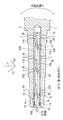
図1において、1は、回転軸であり、実施形態では自動車用変速機におけるメイン軸とされている。すなわち、回転軸1は、2箇所のジャーナル部1a、1bでもって、それぞれ図示を略す軸受を介して変速機ケーシングに回転自在に保持されるようになっている。そして、回転軸1には、ジャーナル部1a、1bの間おいて、互いに軸方向に間隔をあけて複数のギア(図示略)が保持されている。実施形態では、回転軸1が、手動変速機におけるメイン軸用とされている。すなわち、常時噛み合い式の手動変速機にあっては、メイン軸と平行にカウンタ軸(図示略)が配設されて、メイン軸に保持された変速用ギアとカウンタ軸に保持された変速用ギアとが常時噛み合う構成とされているが、回転軸1が上記メイン軸として利用されるものとなっている。
In FIG. 1,
回転軸1には、軸方向に伸びる主オイル孔2が形成されている。主オイル孔2は、回転軸1の一端側(図1左端側)がオイル導入口2aとして開口され、他端側は閉じられている。回転軸1には、主オイル孔2に連通する複数のオイル出口孔3A〜3Dが形成されている。各オイル出口孔3A〜3Dは、それぞれ、回転軸1の軸線を通って直径方向に貫通するように形成されている。勿論、オイル出口孔3A〜3Dの形成位置は、潤滑等に要求される部位に対応した位置に形成される。
A
主オイル孔2内には、図2に示すようなオイル供給管10が挿入されている。このオイル供給管10は、合成樹脂によって断面略円環状に形成されて、主オイル孔1よりも若干短く形成されている。このオイル供給管10の一端側(オイル導入口2a側)はオイル導入口10aとして開口され、他端側はほぼ閉じられている(円筒状部材の他端側を閉じたような形状設定)。
An
オイル供給管10は、その内部が、軸方向に伸びるオイル通路10bとされる。オイル供給管10には、それぞれ径方向に伸びる複数の連通孔11A〜11Dが形成されている。連通孔11A〜11Dは、上記オイル通路10bに連なると共に、オイル供給管10の外面側に開口されている。そして、連通孔11A〜11Dの形成位置は、回転軸1のオイル出口孔3A〜3Dの形成位置に対応している。連通孔11A〜11Dの有効開口面積は、主オイル孔1の奥側に位置するほど大きくなるように設定されている。
The
上記連通孔11Aによって、オイル通路10bとオイル出口孔3Aとが連通される。連通孔11Bによって、オイル通路10bとオイル出口孔3Bとが連通される。連通孔11Cによって、オイル通路10bとオイル出口孔3Cとが連通される。連通孔11Dによって、オイル通路10bとオイル出口孔3Dとが連通される。
The
オイル供給管10は、後述するように、その一端部側に形成された取付突起部12が、回転軸1の一端部に形成された取付凹部としての取付開口1c内に嵌合されている。これにより、オイル供給管10は、回転軸1に対して、軸方向および径方向に位置決めされる。また、オイル供給管10は、ややきつめに主オイル孔2内に嵌合されて、回転軸1とオイル供給管10とが一体回転するようにされるが、上記取付突起部12の取付開口1cへの嵌合によって、この一体回転の機能がより確実に確保される。
As will be described later, the
また、オイル供給管10には、後述するように、その一端部側において、複数の弾性突起部13が形成されている。この弾性突起部13は、径方向対称位置に一対設けられ、この一対の弾性突起部13が軸方向に小間隔をあけて2組設けられている。弾性突起部13は、外力が作用しない状態では、弾性突起部13を含む部分でのオイル供給管10の最大外径が、主オイル孔2の内径よりも大きくなるように設定されており、径方向内方側への外力を受けると、弾性変形されて、弾性突起部13を含めてオイル供給管10が全体的に主オイル孔1内に挿入可能とされる。この弾性突起部13によって、主オイル孔2内に挿入、嵌合されたオイル供給管10のがたつきが確実に防止される。
The
オイル供給管10の内面には、螺旋状のガイド溝20が形成されている。このガイド溝20は、オイル供給管10の一端側から他端側に向けて連続して形成されている。具体的には、ガイド溝20は、前記取付突起部12よりも若干オイル導入口10aに近い側から始まって、もっとも奥側に位置する連通孔11Aにまで達する長さとされている。ガイド溝20は、オイル導入口10a側から見たとき、時計回りあるいは反時計回りのいずれかの方向で、徐々にオイル通路10aの奥側に向かうように渦巻くようにして形成されている。
A
オイル供給管10は、後述するように、径方向に2つに分割された断面略半円環状の半割部材10Aと10Bとを結合することにより構成されている。図10に、半割部材10A、10Bに着目して、ガイド溝20の断面形状(ガイド溝20と直交する方向での断面形状)が示される。図10に示すように、ガイド溝20の内面は、その最底部を境にして2つの円弧面によって形成されて、オイル通路10bに対してはエッジ部αを形成するようにして開口されている(オイルの切れ向上)。
As will be described later, the
オイル供給管10のオイル導入口10a(主オイル孔2のオイル導入口2a)には、図示を略す接続部材が接続されて、この接続部材を介して、図示を略すオイルポンプからオイル供給管10内(つまりオイル通路10b)にオイルが圧送される。オイル通路10b内に供給されたオイルは、連通孔11A〜11Dからオイル出口孔3A〜3Dを通って、え変速機ケーシング内に吐出されて、オイル出口孔3A〜3D付近の摺動部やギア部分が潤滑される。
A connection member (not shown) is connected to the
ここで、回転軸1が回転されると、オイル供給管10も回転軸1と一体的に回転される。これにより、オイル供給管10内のオイルは、螺旋状のガイド溝20に沿って、オイル供給管10の奥側へとスムーズに供給されることになる。すなわち、回転軸1(つまりオイル供給管10)の回転に伴って発生する遠心力により、オイル通路10b内のオイルは、オイル供給管10の内面に押しつけられようとし、ガイド溝20内に十分にオイルが導入されることになる。ガイド溝20内のオイルは、回転軸1の軸線に対する接線方向の分力の作用によって、ガイド溝20に沿って、オイル通路10bの奥側へと導かれることになる。これにより、オイル圧送圧力が同じであれば、よりスムーズにオイルがオイル通路10bの奥側へと流動されることになる。また、オイル通路10bの奥側に向かうオイルの流動性が従来と同じ程度でよければ、オイルの圧送圧力を従来よりも小さくすることができる。
Here, when the
上述したガイド溝20に沿うオイルの流れについて、図1を参照しつつ説明する。まず、回転軸1つまりオイル供給管10が、オイル導入口2a(10a)側から見て反時計方向に回転される場合を考える。このとき、螺旋状のガイド溝20は、オイル導入口2a(10a)側から見て、時計回りに回動するようにしてオイル供給管10の奥側へと形成されている。この場合、ガイド溝20内のオイルは、回転軸1の回転に対してその場に留まろうとする慣性力Fが作用するが、慣性力Fの分力として、ガイド溝20と直交する方向の分力F1と、ガイド溝20に沿う方向の分力F2とが発生する。そして、分力F2が、ガイド溝20内のオイルをオイル供給管20の奥側へと流動させる力として作用することになる。分力F2は、ガイド溝20のいずれの位置でも発生することになり、ガイド溝20の伸び方向がオイル供給管10の軸線と平行に近づくほど(図1において、オイル供給管10の軸線に対するガイド溝20の傾斜角度が小さいほど)、分力F2が大きくなって、オイル供給管10の奥側へとオイルを流動させる作用が強くなる。なお、オイル導入口2a側から見たときに、回転軸1の回転方向を時計方向としたときは、螺旋状のガイド溝20を反反時計回りでもってオイル供給管10の奥側へと位置するように形成すればよい。
The flow of oil along the
オイル出口孔3A〜3Dから吐出されるオイルは、回転軸1の回転速度が小さいときは、ほぼ径方向外方側に向かうようにされる。そして、回転軸1の回転速度が大きくなると、図11に示すように、オイル出口孔3A〜3Dから吐出されたオイルは、四方八方に広く飛散されることになる。勿論、オイル出口孔3A〜3D(これに対応した連通孔11A〜1D)の数や設定位置は、所望潤滑位置に応じて適宜選択すればよい。
The oil discharged from the oil outlet holes 3A to 3D is directed substantially outward in the radial direction when the rotational speed of the
次に、オイル供給管10の具体的な構造や製造の点について、図2〜図7を参照しつつ説明する。まず、オイル供給管10は、前述のように、径方向に2分割された2つの半割部材10Aと10Bとを結合することにより構成される。図2は、2つの半割部材10Aと10Bとの結合状態(組立状態)を示すものであり、図3は分解状態を示し、図4は分解状態での側面断面図を示す。各半割部材10Aと10Bとは、それぞれ合成樹脂により形成(例えば射出成形)されている。
Next, a specific structure and manufacturing point of the
2つの半割部材10Aと10Bとを結合するため、一方の半割部材10Aの周方向各端部には、係止部としての係止爪部31が一体成形されている。この係止爪部31は、半割部材10Aの周方向端部から、突出するように形成されている。
In order to couple the two halved
他方の半割部材10Bの周方向各端部には、前記係止爪部31に対応して、被係止部としての係止爪部32が一体成形されている。この係止爪部32は、半割部材10Bの外方側へ突出しないように形成されている。そして、係止爪部32の形成位置は、前記係止爪部31が位置させることのできるように凹部33が形成されている。
At each end in the circumferential direction of the
係止爪部31、32は、それぞれオイル供給管10の軸方向に伸びるように形成されている。両係止爪部31と32とを係止させるには、まず、図5に示すように、2つの半割部材10Aと10Bとを軸方向に若干ずらした位置関係として、係止爪部31が前記凹部33と整合した図5に示す位置関係とする。図5の状態から、2つの半割部材10Aと10Bとを接近させて、係止爪部31が凹部33に位置させた図6の状態とする。この後、係止爪部31が係止爪部32に接近するように、2つの半割部材10Aと10Bとを軸方向にスライド変位させて、最終的に、係止爪部31を係止爪部32に係止させる。これにより、2つの半割部材10Aと10Bとが結合された図2に示す組立状態とされる。
The locking
なお、上記係止爪部31と係止爪部32とは、半割部材10A、10Bの周方向一端部側では軸方向に間隔をあけて例えば3個設けられ、周方向他端部側では軸方向に間隔をあけて2個設けられているが、その数は適宜設定できるものである。
In addition, the said latching
図8は、前述した取付突起部12の詳細を示すものである。すなわち、半割部材10Bの周方向中央部には、平面視でコ字状の切欠部35を形成することにより、軸方向に短く伸びる脚部36が形成される。そして、脚部36の先端部に、径方向外方側に向けて突出する取付突起部12が一体成形されている。脚部36の弾性変形を利用して、回転軸1に形成された取付開口1c内に、節度感をもって取付突起部12が嵌合されることになり、また嵌合後は、嵌合状態が確実に維持されることになる。なお、実施形態では、取付突起部12およびこれに対応した取付開口1cは、全体として1つのみ設けてあるが、オイル供給管10の径方向に間隔をあけて複数設けたり、軸方向に間隔をあけて複数設けることもできる。なお、取付凹部としての取付開口1cは、貫通した孔形状とすることなく、非貫通となる有底状であってもよい。
FIG. 8 shows the details of the mounting
図9は、前述した弾性突起部13の詳細を示すものである。すなわち、半割部材10A、10Bに対して、径方向外方側に向けて突出する突起部13aを形成する一方、この突起部12a部分の径方向内方側において、空洞部13bが形成される。空洞部13bは、突起部13aに対して軸方向に長く伸びている。これにより、外力を受けない状態では、突起部13aは半割部材10A、10Bの径方向外方側へ突出されているが、径方向内方側への外力を受けると、空洞部13bが径方向に圧縮変形されて(弾性変形されて)、突起部13aが径方向内方側へと引っ込められることになる。オイル供給管10を主オイル孔2内に挿入した状態では、突起部13aが主オイル孔2の内面に弾性的に当接して、回転軸1に対するオイル供給管10のがたつきが防止されることになる。なお、上述したような弾性突起部13は、オイル供給管10の各端部に設けるようにしてもよく、また中間位置に設けるようにしてもよく、その設定数は適宜選択できるものである。
FIG. 9 shows the details of the
図4に示すように、半割部材10Aの奥側端壁部に、軸方向に伸びる係止爪部15が形成される一方、半割部材10Bの奥側端壁部には軸方向に伸びる係止孔部16が形成されている。2つの半割部材10Aと10Bとを結合する過程において、係止爪部15を係止孔部16に挿入することにより、2つの半割部材10Aと10Bとの径方向の分離がより一層強固に規制される。
As shown in FIG. 4, a locking
図12〜図15は、本発明の第2の実施形態を示すものであり、前記実施形態と同一構成要素には同一符合を付してその重複した説明は省略する(このことは、以下の第3の実施形態についても同じ)。 12 to 15 show a second embodiment of the present invention. The same components as those in the above embodiment are given the same reference numerals, and redundant description thereof is omitted (this is described below). The same applies to the third embodiment).
本実施形態では、2つの半割部材10Aと10Bとを、オイル供給管10の径方向に接近させることによって結合するようにしてある。すなわち、図14に示すように、一方の半割部材10Aには、係止部としての係止爪部41が突出形成される一方、他方の半割部材10Bには、被係止部としての係止孔部41が形成されている。半割部材10Aと10Bとを径方向から接近させて、係止爪部41と係止孔部42に係止させることにより、半割部材10Aと10Bとの結合状態が維持される。係止爪部41と係止孔部42の数は設定位置は適宜選択することができる。
In the present embodiment, the two halved
また、一方の半割部材10Aには、位置決め突起部43が突出形成される一方、他方の半割部材10Bには、位置決め孔部44が形成されている。位置決め突起部43を位置決め孔部44に嵌合させることにより、2つの半割部材10Aと10Bとが位置決めされた状態での結合が確保される。このような位置決め突起部43と位置決め孔部44との数や設定位置は、適宜選択できる。なお、ガイド溝20は、前記実施形態の場合に比して、その形成ピッチが小さくされている(図1に示す分力F2が前記実施形態の場合に比して小さくなる設定)。なお、本実施形態では、オイル供給管10は、その端部がいずれも大きく開口された筒状とされている。
Further, a
図16〜図20は、本発明の第3の実施形態を示すものである。本実施形態では、2つの半割部材10Aと10Bとを、ヒンジ51を含めて互いに一体成形(例えば射出成形)するようにしてある。すなわち、図16は、成形された直後の状態を示し、一方の半割部材10Aの周方向一端部側と、他方の半割部材10Bの周方向一端部側とが、ヒンジ51を介して連結された状態とされる。この図16に示す状態から、ヒンジ51を中心にして、一方の半割部材10Aが他方の半割部材10Bに重なるように回動させる(略180度回動させる)ことにより、図17実線で示すような組立状態とされる。
16 to 20 show a third embodiment of the present invention. In the present embodiment, the two
図17の組立状態を維持(保持)するために、一方の半割部材10Aの他端部と、他方の半割部材10Bの他端部とには、係止部としての係止爪部52と被係止部53とが一体形成される。係止爪部52は、周方向に延びており、結合状態では、係止爪部52が周方向一方側から被係止部53に接近して、最終的に被係止部53に係止される。(図20の状態から図19の状態へと変更される)。このような係止爪部52と被係止部53とは、オイル供給管10の軸方向に間隔をあけて複数設けられているが、その数や設定位置は適宜選択できる。
In order to maintain (hold) the assembled state of FIG. 17, a locking
ヒンジ51は、軸方向に間隔をあけて、軸方向幅が小さい薄板状として形成されている。そして、図19に示すように、組立状態では、ヒンジ51を含むオイル供給管10の最大外径が、主オイル孔2の内径以下となるように設定されている。具体的には、各半割部材10A、10Bのうち、ヒンジ51付近の肉厚を薄くするようにしてある。なお、本実施形態では、オイル供給管10は、その端部がいずれも大きく開口された筒状とされている。
The
図21、図22は、本発明の第4の実施形態を示すものである。本実施形態では、弾性突起部13を、半割部材10Aと10Bとの左右の境界部位にも1つづつ設けるようにして、合計で6個設けてある。これにより、オイル供給管10の周方向においては、略90度間隔で合計4個の弾性突起部13が存在することとなって、オイル供給管10を主オイル孔2内に挿入、設置したときに、径方向のがたつきをより確実に防止することができる。なお、半割部材10Aと10Bとの境界(分割)部位に設けられた2つの弾性突起部13は、半割部材10Aと10Bに分割された形式でもって形成されて、この半割部材10Aと10Bとを組み合わせたときに構成されるようになっている。なお、弾性突起部13のオイル供給管10の周方向回りの数や軸線方向の数は、適宜設定できるものである。
21 and 22 show a fourth embodiment of the present invention. In the present embodiment, six
以上実施形態について説明したが、本発明は、実施形態に限定されるものではなく、特許請求の範囲の記載された範囲において適宜の変更が可能であり、例えば次のような場合をも含むものである。オイル供給管10を、金属や複合材によって形成してもよい。係止部や被係止部の構造は適宜のものを採択することができ、またある実施形態において示したものを他の実施形態について適用する等のこともできる。回転軸1としては、変速機用に限らないものであり、適宜の機器類における回転軸について本発明を適用することができる。
Although the embodiment has been described above, the present invention is not limited to the embodiment, and can be appropriately changed within the scope described in the scope of claims. For example, the invention includes the following cases. . The
ガイド溝20を、例えば互いに略平行に2本以上形成してもよい。また、ガイド溝20は、オイル供給管10の軸方向に分割された複数本に分割ガイド溝として形成することもでき、この分割ガイド溝の軸方向端部同士は互いに連通されていないが、軸方向で重なるような配置関係としてもよい。ガイド溝20が連通孔11A〜11Dを通るように設定するのが好ましいが、連通孔11A〜11Dを通らないような設定であってもよい。ガイド溝20が連通孔を通らないときは、連通孔11A〜11Dに至る螺旋状の分岐ガイド溝をガイド溝20から分岐させて形成するようにしてもよい。勿論、本発明の目的は、明記されたものに限らず、実質的に好ましいあるいは利点として表現されたものを提供することをも暗黙的に含むものである。
For example, two or
本発明は、例えば変速機の回転軸に使用するオイル供給管として好適である。 The present invention is suitable, for example, as an oil supply pipe used for a rotating shaft of a transmission.
1:回転軸
1c:取付開口(取付凹部)
2:主オイル孔
2a:オイル導入口
3A〜3D:オイル出口孔
10:オイル供給管
10a:オイル導入口
10A、10B:半割部材
11A〜11D:連通孔
12:取付突起部
13:弾性突起部
20:ガイド溝
31:係止爪部(係止部)
32:係止爪部(被係止部)
41:傾斜爪部(係止部)
42:係止孔部(被係止部)
43:位置決め突起部
44:位置決め孔部
51:ヒンジ
52:係止爪部(係止部)
53:被係止部
1: Rotating
2:
32: Locking claw part (locked part)
41: Inclined claw part (locking part)
42: Locking hole (locked part)
43: Positioning projection 44: Positioning hole 51: Hinge 52: Locking claw (locking)
53: Locked part
Claims (10)
内面に、軸方向一端側から供給されたオイルを回転に応じて他端側へ向けて流動させる螺旋状のガイド溝が形成され、
径方向に延びて、内部のオイルを外部へ導くための連通孔が形成され、
径方向に2分割された断面略半円環状の半割部材同士を結合することにより構成されており、
一方の前記半割部材に係止部が一体に形成されると共に、他方の前記半割部材に被係止部が一体に形成されて、該係止部を該被係止部に係止させることによって該2つの半割部材同士が結合されており、
前記2つの半割部材の結合状態で、前記係止部と前記被係止部とを含むオイル供給管の外径が、前記主オイル孔の内径以下とされ、
前記各半割部材が、それぞれ、前記係止部と前記被係止部とを含めて全体的に合成樹脂によって形成されている、
ことを特徴とするオイル供給管。 An oil supply pipe that is inserted into an axially extending main oil hole formed in the rotating shaft and used to rotate integrally with the rotating shaft,
A spiral guide groove is formed on the inner surface to flow the oil supplied from one end side in the axial direction toward the other end side according to the rotation.
A communication hole is formed extending in the radial direction to guide the internal oil to the outside.
It is configured by combining the half members together of two divided section substantially semicircular annular radially
A locking portion is integrally formed on one of the half members, and a locked portion is integrally formed on the other half member, and the locking portion is locked to the locked portion. The two halved members are joined together,
In the coupled state of the two halved members, the outer diameter of the oil supply pipe including the locking portion and the locked portion is not more than the inner diameter of the main oil hole,
Each of the half members is formed entirely of a synthetic resin including the locking portion and the locked portion, respectively.
An oil supply pipe characterized by that.
前記ガイド溝が、前記連通孔を通るように形成されている、ことを特徴とするオイル供給管。 In claim 1,
The oil supply pipe, wherein the guide groove is formed so as to pass through the communication hole.
前記2つの半割部材同士は、ヒンジによって互いに結合されており、
前記ヒンジを中心にした回動によって前記2つの半割部材同士を重ね合わせて断面略円環状に形成した状態で、前記係止部を前記被係止部に係止させることにより、該2つの半割部材の結合状態が保持される、
ことを特徴とするオイル供給管。 In claim 1 or claim 2,
The two half members each other, Ri Contact are coupled together by a hinge,
By the rotation centered on the front Symbol hinge by superimposing the two half members together in a state of forming the cross section annular by locking the locking portion to the locked portion, the two The combined state of the two half members is maintained,
An oil supply pipe characterized by that.
前記係止部が、前記ヒンジとは反対側端部に形成された係止爪部とされ、
前記被係止部が、前記ヒンジとは反対側端部に形成されて前記係止爪部が挿入される係止孔部とされている、
ことを特徴とするオイル供給管。 In claim 3,
The locking portion is a locking claw portion formed at the end opposite to the hinge,
The locked portion is formed at an end portion opposite to the hinge and is a locking hole portion into which the locking claw portion is inserted.
An oil supply pipe characterized by that.
前記2つの半割部材同士を結合した状態で、前記ヒンジを含む外径が、前記主オイル孔の内径以下となるように設定されている、ことを特徴とするオイル供給管。 In claim 3 or claim 4,
An oil supply pipe, wherein an outer diameter including the hinge is set to be equal to or smaller than an inner diameter of the main oil hole in a state where the two halved members are coupled to each other.
前記2つの半割部材は、互いに別体として形成され、
一方の前記半割部材の周方向各端部に、前記係止部としての係止爪部が形成され、
他方の前記半割部材の周方向各端部に、前記2つの半割部材同士を軸方向にずらすことによって前記係止爪部が係止される前記被係止部としての係止孔部が形成されている、
ことを特徴とするオイル供給管。 In claim 1 or claim 2,
The two half members are formed separately from each other,
Circumferentially each end of one of said half members, the locking pawl serving as the locking portion is formed,
Circumferentially each end of the other of said half members, the locking hole as the locked portion of the locking claw portion is engaged by displacing the two half members together in the axial direction Formed,
An oil supply pipe characterized by that.
外面に、径方向外方側に突出して前記主オイル孔の内面に形成された取付凹部に嵌合される取付突起部が形成されている、ことを特徴とするオイル供給管。 In any one of Claims 1 thru | or 6,
An oil supply pipe, characterized in that a mounting protrusion is formed on the outer surface so as to protrude outward in the radial direction and fit into a mounting recess formed in the inner surface of the main oil hole.
外周面に、径方向外方側に向けて突出されて前記主オイル孔の内面に弾力的に当接される弾性突起部が形成されている、ことを特徴とするオイル供給管。 In any one of Claims 1 thru | or 7,
An oil supply pipe, characterized in that an elastic protrusion is formed on an outer peripheral surface so as to protrude outward in the radial direction and elastically contact the inner surface of the main oil hole.
前記連通孔が、軸方向に間隔をあけて複数形成され、
前記螺旋状のガイド溝が、軸方向一端側から他端側へ連続して形成されている、
ことを特徴とするオイル供給管。 In any one of Claims 1 thru | or 8,
A plurality of the communication holes are formed at intervals in the axial direction,
The spiral guide groove is continuously formed from one end side in the axial direction to the other end side.
An oil supply pipe characterized by that.
前記回転軸が、変速機ケーシングに回転自在に保持された変速機用形状とされている、ことを特徴とするオイル供給管。
In any one of Claims 1 thru | or 9 ,
An oil supply pipe, wherein the rotation shaft has a transmission shape that is rotatably held in a transmission casing.
Priority Applications (1)
| Application Number | Priority Date | Filing Date | Title |
|---|---|---|---|
| JP2012146509A JP5956848B2 (en) | 2012-06-29 | 2012-06-29 | Oil supply pipe |
Applications Claiming Priority (1)
| Application Number | Priority Date | Filing Date | Title |
|---|---|---|---|
| JP2012146509A JP5956848B2 (en) | 2012-06-29 | 2012-06-29 | Oil supply pipe |
Publications (3)
| Publication Number | Publication Date |
|---|---|
| JP2014009744A JP2014009744A (en) | 2014-01-20 |
| JP2014009744A5 JP2014009744A5 (en) | 2015-06-18 |
| JP5956848B2 true JP5956848B2 (en) | 2016-07-27 |
Family
ID=50106629
Family Applications (1)
| Application Number | Title | Priority Date | Filing Date |
|---|---|---|---|
| JP2012146509A Expired - Fee Related JP5956848B2 (en) | 2012-06-29 | 2012-06-29 | Oil supply pipe |
Country Status (1)
| Country | Link |
|---|---|
| JP (1) | JP5956848B2 (en) |
Families Citing this family (7)
| Publication number | Priority date | Publication date | Assignee | Title |
|---|---|---|---|---|
| JP6608387B2 (en) * | 2014-11-10 | 2019-11-20 | 株式会社ミツバ | Motor with reduction mechanism |
| CN110388450B (en) | 2018-04-20 | 2023-07-04 | 丰田自动车株式会社 | Lubrication device for power transmission device |
| JP7063077B2 (en) | 2018-04-20 | 2022-05-09 | トヨタ自動車株式会社 | Resin pipe and its manufacturing method |
| JP2020045938A (en) * | 2018-09-18 | 2020-03-26 | 本田技研工業株式会社 | Lubrication oil supply device |
| WO2020250694A1 (en) * | 2019-06-13 | 2020-12-17 | ジヤトコ株式会社 | Power transmission device and method for manufacturing power transmission device |
| JP7333266B2 (en) * | 2019-12-26 | 2023-08-24 | 株式会社Subaru | Cooling mechanism of differential |
| JP6858291B1 (en) * | 2020-06-17 | 2021-04-14 | 古河電気工業株式会社 | Protective member for cable take-out, cable take-out structure from pipeline having cable take-out protective member, and laminated structure of conduit of square electric conduit |
Family Cites Families (1)
| Publication number | Priority date | Publication date | Assignee | Title |
|---|---|---|---|---|
| JP4927404B2 (en) * | 2006-01-10 | 2012-05-09 | 愛知機械工業株式会社 | transmission |
-
2012
- 2012-06-29 JP JP2012146509A patent/JP5956848B2/en not_active Expired - Fee Related
Also Published As
| Publication number | Publication date |
|---|---|
| JP2014009744A (en) | 2014-01-20 |
Similar Documents
| Publication | Publication Date | Title |
|---|---|---|
| JP5956848B2 (en) | Oil supply pipe | |
| JP2014009744A5 (en) | ||
| WO2015141783A1 (en) | Baffle plate for differential device | |
| US10408221B2 (en) | Turbocharger | |
| EP3022453B1 (en) | Thrust washer | |
| JP2006518023A (en) | Thrust bearing with spacer member | |
| CN104246256A (en) | Rolling bearing | |
| WO2016121334A1 (en) | Fuel pump | |
| JP2010127318A (en) | Lubricating structure of rotating shaft | |
| WO2016113813A1 (en) | Fuel pump | |
| JP6418094B2 (en) | Fuel pump | |
| CN114072602B (en) | Sealing ring | |
| US9841018B2 (en) | Fluid pump | |
| JP6443351B2 (en) | Selectable one-way clutch | |
| US20060273524A1 (en) | Ring seal with an anti-rotation tab | |
| WO2016166936A1 (en) | Fuel pump | |
| US9377095B2 (en) | Differential device | |
| US9488172B2 (en) | Pump assembly for a vehicle | |
| JP6011973B2 (en) | Bearing detent structure in transmission | |
| CN101529124B (en) | Fluid power transmission | |
| JP6328386B2 (en) | Scroll type fluid machine and gasket thereof | |
| KR20090061945A (en) | Speed gear of manual transmission for vehicle and synchronizing device of the same | |
| JP2007327621A (en) | Lubrication structure for oldham's coupling | |
| WO2017187928A1 (en) | Compound pump | |
| JP2020037969A (en) | bush |
Legal Events
| Date | Code | Title | Description |
|---|---|---|---|
| A711 | Notification of change in applicant |
Free format text: JAPANESE INTERMEDIATE CODE: A711 Effective date: 20150319 |
|
| A521 | Request for written amendment filed |
Free format text: JAPANESE INTERMEDIATE CODE: A523 Effective date: 20150327 |
|
| A521 | Request for written amendment filed |
Free format text: JAPANESE INTERMEDIATE CODE: A821 Effective date: 20150319 |
|
| A521 | Request for written amendment filed |
Free format text: JAPANESE INTERMEDIATE CODE: A821 Effective date: 20150327 |
|
| A621 | Written request for application examination |
Free format text: JAPANESE INTERMEDIATE CODE: A621 Effective date: 20150501 |
|
| A131 | Notification of reasons for refusal |
Free format text: JAPANESE INTERMEDIATE CODE: A131 Effective date: 20160301 |
|
| A977 | Report on retrieval |
Free format text: JAPANESE INTERMEDIATE CODE: A971007 Effective date: 20160229 |
|
| A521 | Request for written amendment filed |
Free format text: JAPANESE INTERMEDIATE CODE: A523 Effective date: 20160428 |
|
| TRDD | Decision of grant or rejection written | ||
| A01 | Written decision to grant a patent or to grant a registration (utility model) |
Free format text: JAPANESE INTERMEDIATE CODE: A01 Effective date: 20160524 |
|
| A61 | First payment of annual fees (during grant procedure) |
Free format text: JAPANESE INTERMEDIATE CODE: A61 Effective date: 20160617 |
|
| R150 | Certificate of patent or registration of utility model |
Ref document number: 5956848 Country of ref document: JP Free format text: JAPANESE INTERMEDIATE CODE: R150 |
|
| R250 | Receipt of annual fees |
Free format text: JAPANESE INTERMEDIATE CODE: R250 |
|
| R250 | Receipt of annual fees |
Free format text: JAPANESE INTERMEDIATE CODE: R250 |
|
| R250 | Receipt of annual fees |
Free format text: JAPANESE INTERMEDIATE CODE: R250 |
|
| LAPS | Cancellation because of no payment of annual fees |