JP5956187B2 - Method for molding fiber reinforced plastic molding with three-dimensional additive - Google Patents
Method for molding fiber reinforced plastic molding with three-dimensional additive Download PDFInfo
- Publication number
- JP5956187B2 JP5956187B2 JP2012040773A JP2012040773A JP5956187B2 JP 5956187 B2 JP5956187 B2 JP 5956187B2 JP 2012040773 A JP2012040773 A JP 2012040773A JP 2012040773 A JP2012040773 A JP 2012040773A JP 5956187 B2 JP5956187 B2 JP 5956187B2
- Authority
- JP
- Japan
- Prior art keywords
- resin
- fiber
- molding
- mold
- reinforced plastic
- Prior art date
- Legal status (The legal status is an assumption and is not a legal conclusion. Google has not performed a legal analysis and makes no representation as to the accuracy of the status listed.)
- Active
Links
- 238000000465 moulding Methods 0.000 title claims description 59
- 229920002430 Fibre-reinforced plastic Polymers 0.000 title claims description 58
- 239000011151 fibre-reinforced plastic Substances 0.000 title claims description 58
- 239000000654 additive Substances 0.000 title claims description 31
- 230000000996 additive effect Effects 0.000 title claims description 29
- 238000000034 method Methods 0.000 title claims description 27
- 238000010137 moulding (plastic) Methods 0.000 title claims description 7
- 229920005989 resin Polymers 0.000 claims description 118
- 239000011347 resin Substances 0.000 claims description 118
- 239000000835 fiber Substances 0.000 claims description 104
- 239000012783 reinforcing fiber Substances 0.000 claims description 31
- 229920005992 thermoplastic resin Polymers 0.000 claims description 24
- 239000000463 material Substances 0.000 claims description 23
- 229920001187 thermosetting polymer Polymers 0.000 claims description 22
- 238000002844 melting Methods 0.000 claims description 6
- 230000008018 melting Effects 0.000 claims description 6
- 238000002156 mixing Methods 0.000 claims description 4
- 229920000049 Carbon (fiber) Polymers 0.000 description 20
- 239000004917 carbon fiber Substances 0.000 description 20
- VNWKTOKETHGBQD-UHFFFAOYSA-N methane Chemical compound C VNWKTOKETHGBQD-UHFFFAOYSA-N 0.000 description 15
- 230000003014 reinforcing effect Effects 0.000 description 7
- 239000004744 fabric Substances 0.000 description 6
- 239000002131 composite material Substances 0.000 description 5
- 239000008188 pellet Substances 0.000 description 5
- 238000003825 pressing Methods 0.000 description 5
- 229910000831 Steel Inorganic materials 0.000 description 4
- 229910052751 metal Inorganic materials 0.000 description 4
- 239000002184 metal Substances 0.000 description 4
- 230000002093 peripheral effect Effects 0.000 description 4
- 229920005668 polycarbonate resin Polymers 0.000 description 4
- 239000004431 polycarbonate resin Substances 0.000 description 4
- -1 polyparaphenylene benzbisoxazole Polymers 0.000 description 4
- 239000010959 steel Substances 0.000 description 4
- 238000001746 injection moulding Methods 0.000 description 3
- 239000004925 Acrylic resin Substances 0.000 description 2
- 229920000178 Acrylic resin Polymers 0.000 description 2
- 229920002748 Basalt fiber Polymers 0.000 description 2
- ZOXJGFHDIHLPTG-UHFFFAOYSA-N Boron Chemical compound [B] ZOXJGFHDIHLPTG-UHFFFAOYSA-N 0.000 description 2
- 239000004677 Nylon Substances 0.000 description 2
- 239000004696 Poly ether ether ketone Substances 0.000 description 2
- 239000004952 Polyamide Substances 0.000 description 2
- 239000004697 Polyetherimide Substances 0.000 description 2
- 239000004734 Polyphenylene sulfide Substances 0.000 description 2
- 239000004743 Polypropylene Substances 0.000 description 2
- RTAQQCXQSZGOHL-UHFFFAOYSA-N Titanium Chemical compound [Ti] RTAQQCXQSZGOHL-UHFFFAOYSA-N 0.000 description 2
- 229920002978 Vinylon Polymers 0.000 description 2
- 229920000122 acrylonitrile butadiene styrene Polymers 0.000 description 2
- 239000004760 aramid Substances 0.000 description 2
- 229920003235 aromatic polyamide Polymers 0.000 description 2
- 229910052796 boron Inorganic materials 0.000 description 2
- 239000003822 epoxy resin Substances 0.000 description 2
- 230000004927 fusion Effects 0.000 description 2
- 239000003365 glass fiber Substances 0.000 description 2
- 239000011159 matrix material Substances 0.000 description 2
- 239000000203 mixture Substances 0.000 description 2
- 229920001778 nylon Polymers 0.000 description 2
- 239000005011 phenolic resin Substances 0.000 description 2
- 229920001652 poly(etherketoneketone) Polymers 0.000 description 2
- 229920002647 polyamide Polymers 0.000 description 2
- 229920000647 polyepoxide Polymers 0.000 description 2
- 229920000728 polyester Polymers 0.000 description 2
- 229920002530 polyetherether ketone Polymers 0.000 description 2
- 229920001601 polyetherimide Polymers 0.000 description 2
- 229920000069 polyphenylene sulfide Polymers 0.000 description 2
- 229920001155 polypropylene Polymers 0.000 description 2
- 229920005749 polyurethane resin Polymers 0.000 description 2
- 239000007787 solid Substances 0.000 description 2
- 238000007711 solidification Methods 0.000 description 2
- 230000008023 solidification Effects 0.000 description 2
- 229920003002 synthetic resin Polymers 0.000 description 2
- 239000000057 synthetic resin Substances 0.000 description 2
- 229920001169 thermoplastic Polymers 0.000 description 2
- 239000004416 thermosoftening plastic Substances 0.000 description 2
- 239000010936 titanium Substances 0.000 description 2
- 229910052719 titanium Inorganic materials 0.000 description 2
- 229920001567 vinyl ester resin Polymers 0.000 description 2
- OKTJSMMVPCPJKN-UHFFFAOYSA-N Carbon Chemical compound [C] OKTJSMMVPCPJKN-UHFFFAOYSA-N 0.000 description 1
- JHWNWJKBPDFINM-UHFFFAOYSA-N Laurolactam Chemical compound O=C1CCCCCCCCCCCN1 JHWNWJKBPDFINM-UHFFFAOYSA-N 0.000 description 1
- 229920000299 Nylon 12 Polymers 0.000 description 1
- 229920000297 Rayon Polymers 0.000 description 1
- 229910052799 carbon Inorganic materials 0.000 description 1
- 239000004918 carbon fiber reinforced polymer Substances 0.000 description 1
- 238000001816 cooling Methods 0.000 description 1
- 230000000694 effects Effects 0.000 description 1
- 238000005516 engineering process Methods 0.000 description 1
- 238000002474 experimental method Methods 0.000 description 1
- 239000003733 fiber-reinforced composite Substances 0.000 description 1
- 238000010438 heat treatment Methods 0.000 description 1
- 238000005470 impregnation Methods 0.000 description 1
- 238000002347 injection Methods 0.000 description 1
- 239000007924 injection Substances 0.000 description 1
- 239000000088 plastic resin Substances 0.000 description 1
- 239000004417 polycarbonate Substances 0.000 description 1
- 229920001225 polyester resin Polymers 0.000 description 1
- 239000004645 polyester resin Substances 0.000 description 1
- 239000002964 rayon Substances 0.000 description 1
- 230000002787 reinforcement Effects 0.000 description 1
- 229920006395 saturated elastomer Polymers 0.000 description 1
- 238000007789 sealing Methods 0.000 description 1
- 238000007493 shaping process Methods 0.000 description 1
- 239000000758 substrate Substances 0.000 description 1
- 229920006337 unsaturated polyester resin Polymers 0.000 description 1
- 238000009941 weaving Methods 0.000 description 1
- 239000002759 woven fabric Substances 0.000 description 1
Images


Description
本発明は、熱可塑性樹脂或いは熱硬化性樹脂をマトリクス樹脂とした繊維強化複合材料であって、箱型、平板、カギ型などのシェル構造に、例えばリブやねじ孔などの立体的な補強構造(以下、「立体添加物」という。)を有する立体添加物付き繊維強化プラスチック成形体の成形方法に関するものである。 The present invention is a fiber reinforced composite material using a thermoplastic resin or a thermosetting resin as a matrix resin, and has a three-dimensional reinforcing structure such as a rib or a screw hole in a shell structure such as a box shape, a flat plate, or a key shape. The present invention relates to a method for molding a fiber-reinforced plastic molded article with a three-dimensional additive having (hereinafter referred to as “three-dimensional additive”).
従来、箱型、平板、カギ型などのシェル構造に、例えばリブやねじ孔などの立体的な補強構造などとされる立体添加物を備えた立体添加物付き繊維強化プラスチックを一体化された成形体として成形する方法が種々提案されている。 Conventionally, molded with a three-dimensional additive-added fiber reinforced plastic with a three-dimensional additive, such as a three-dimensional reinforcing structure such as a rib or screw hole, in a shell structure such as a box shape, flat plate, or key shape. Various methods for forming a body have been proposed.
特許文献1は、繊維強化した熱硬化樹脂シートで成形された第1成形品と、射出成形にて成形された熱可塑性合成樹脂から成形された第2成形品とからなる合成樹脂製複合成形体であって、前記第1成形品と前記第2成形品とが熱融着により一体化されていることを特徴とする。同方法は強化繊維と熱硬化性樹脂にて成形されたシェル構造の繊維強化プラスチックを射出成型の型にセットしてから、熱可塑性樹脂を射出成形にて熱融着によりシェル構造に取り付けるものである。 Patent Document 1 discloses a composite molded body made of a synthetic resin comprising a first molded product molded from a fiber reinforced thermosetting resin sheet and a second molded product molded from a thermoplastic synthetic resin molded by injection molding. And the said 1st molded product and the said 2nd molded product are integrated by heat sealing | fusion, It is characterized by the above-mentioned. In this method, a fiber reinforced plastic with a shell structure molded with reinforced fibers and a thermosetting resin is set in an injection mold, and then the thermoplastic resin is attached to the shell structure by heat fusion by injection molding. is there.
特許文献1に記載の成形は、熱硬化性樹脂によるFRP成形と、その後の射出成形の2段成形となりコストがかかる。 The molding described in Patent Document 1 is costly because it is a two-stage molding of FRP molding using a thermosetting resin and subsequent injection molding.
特許文献2は、実質的に2次元ランダムに配向しかつ特定の開繊状態を満たす炭素繊維が熱可塑性樹脂中に存在する複合材料からなるランダム層と、炭素繊維が一方向に引き揃えられた一方向材と熱可塑性樹脂とからなる一方向材層とを有する成形体とすることで、剛性に優れた炭素繊維複合材料を成形するものである。繊維長5mm超100mm以下の炭素繊維と熱可塑性樹脂とから構成されるランダム層と、炭素繊維が一方向に引き揃えられた一方向材と熱可塑性樹脂とからなる一方向材層とをプレス成形して得られる炭素繊維複合成形体である。 In Patent Document 2, a random layer composed of a composite material in which carbon fibers that are oriented in a two-dimensional random manner and satisfy a specific opening state are present in a thermoplastic resin, and the carbon fibers are aligned in one direction. By forming a molded body having a unidirectional material layer made of a unidirectional material and a thermoplastic resin, a carbon fiber composite material having excellent rigidity is molded. Press-molding a random layer composed of carbon fibers with a fiber length of more than 5 mm and not more than 100 mm and a thermoplastic resin, and a unidirectional material layer composed of a unidirectional material in which carbon fibers are aligned in one direction and a thermoplastic resin. It is a carbon fiber composite molded body obtained as described above.
特許文献2に記載の技術では比較的大型な成形物としての成形には適するが、細かなリブ構造やねじ孔などを成形すると付加する立体構造部分の形状が不安定になることや、高さの高い立体構造が成形し難い。 The technique described in Patent Document 2 is suitable for molding as a relatively large molded product, but if a fine rib structure or screw hole is molded, the shape of the added three-dimensional structure becomes unstable, and the height High three-dimensional structure is difficult to mold.
特許文献3には、長繊維基材とSMCなどの短繊維基材とを組み合わせて、リブ構造を有する車両用フードの成形方法が記載されている。特許文献3の成形方法は、比較的大型の成形物に適用されるものである。 Patent Document 3 describes a method for forming a vehicle hood having a rib structure by combining a long fiber base material and a short fiber base material such as SMC. The molding method of Patent Document 3 is applied to a relatively large molded product.
本発明者らは、上記特許文献1、2、3に記載する技術の問題点を解決するために多くの研究実験を行った結果、使用する強化繊維の繊維長さ、含有量、更には、金型の構造、などを調整することによって、一方向や織物形状の連続の強化繊維によるシェル構造に、ねじ孔や細かなリブ構造を有する繊維強化プラスチック成形体を1回のプレス成形にて短時間に成形し得ることを見出した。 As a result of conducting many research experiments in order to solve the problems of the techniques described in Patent Documents 1, 2, and 3, the present inventors have found that the fiber length and content of the reinforcing fibers used are By adjusting the structure of the mold, etc., the fiber reinforced plastic molded body with screw holes and fine rib structure can be shortened by one press molding to the shell structure with continuous reinforcing fiber in one direction or fabric shape. It has been found that it can be molded in time.
本発明は斯かる本発明者らの新規な知見に基づきなされたものである。 The present invention has been made based on such novel findings of the present inventors.
本発明の目的は、箱型、平板、カギ型などのシェル構造に、リブやねじ孔などの立体的な補強構造を有する立体添加物付き繊維強化プラスチック成形体の成形方法を提供することである。 An object of the present invention is to provide a method for molding a fiber-reinforced plastic molded article with a three-dimensional additive having a three-dimensional reinforcing structure such as a rib or a screw hole in a shell structure such as a box shape, a flat plate, or a key shape. .
本発明の他の目的は、箱型、平板、カギ型などのシェル構造に、リブやねじ孔などの立体的な補強構造を有する立体添加物付き繊維強化プラスチックを1回のプレス成形にて短時間に成形することのできる立体添加物付き繊維強化プラスチック成形体の成形方法を提供することである。 Another object of the present invention is to shorten the fiber reinforced plastic with a three-dimensional additive having a three-dimensional reinforcing structure such as a rib or a screw hole into a shell structure such as a box shape, a flat plate, or a key shape by a single press molding. It is an object of the present invention to provide a method for molding a fiber-reinforced plastic molded article with a three-dimensional additive that can be molded in time.
上記目的は本発明に係る立体添加物付き繊維強化プラスチック成形体の成形方法にて達成される。要約すれば、本発明は、繊維長さが0.01mm以上、2.0mm以下の長さの短繊維が5〜50wt%の配合量でランダム配向されたシート状、フレーク状或いはペレット状の熱可塑性樹脂或いは熱硬化性樹脂とされる短繊維強化樹脂と、
熱可塑性樹脂或いは熱硬化性樹脂が含浸された一方向或いは織物の連続強化繊維プリプレグと、
を有する繊維強化プラスチック材を、外金型及び内金型を有する金型による1回のプレス成形により、前記連続強化繊維プリプレグと前記短繊維強化樹脂にて成形された連続繊維層と短繊維層の積層体から成るシェルと、前記短繊維強化樹脂にて成形された立体添加物とを有する繊維強化プラスチック成形体を成形する方法であって、
前記外金型及び前記内金型は、互いに組み合わせて成形加工状態に配置された時、互いに対向配置されて前記外金型と前記内金型との間に前記繊維強化プラスチック成形体を形成するための成形空間を形成する鍔部分を有しており、
前記鍔部分は、前記成形空間から外方へと20mm以上、100mm以下にて前記外金型及び前記内金型の外周辺に延在して形成されており、
対向配置された前記両金型の前記鍔部分のクリアランスを、成形しようとする前記繊維強化プラスチック成形体の前記シェルの板厚(tmm)に対して0.5・t(mm)以上、0.75・t(mm)以下に調整することによって、プレスの圧力を生じさせ、このプレスの圧力によって、樹脂を流動させて前記鍔部分のクリアランスに樹脂をはみ出させることを特徴とする立体添加物付き繊維強化プラスチック成形体の成形方法である。
The above object is achieved by the method for molding a fiber-reinforced plastic molded article with a three-dimensional additive according to the present invention. In summary, the present invention is a sheet-like, flake-like or pellet-like heat in which short fibers having a fiber length of 0.01 mm or more and 2.0 mm or less are randomly oriented at a blending amount of 5 to 50 wt%. A short fiber reinforced resin which is a plastic resin or a thermosetting resin;
Unidirectional or woven continuous reinforcing fiber prepreg impregnated with thermoplastic resin or thermosetting resin;
A continuous fiber layer and a short fiber layer formed of the continuous reinforcing fiber prepreg and the short fiber reinforced resin by one-time press molding using a mold having an outer mold and an inner mold. A method of molding a fiber-reinforced plastic molded body having a shell made of a laminate of the above and a three-dimensional additive molded with the short fiber-reinforced resin,
When the outer mold and the inner mold are arranged in combination with each other, they are arranged opposite to each other to form the fiber-reinforced plastic molded body between the outer mold and the inner mold. And has a flange portion that forms a molding space for
The flange portion is formed to extend outward from the molding space to the outer periphery of the outer mold and the inner mold at 20 mm or more and 100 mm or less,
The clearance of the flange portions of the two molds arranged to face each other is 0.5 · t (mm) or more with respect to the plate thickness (tmm) of the shell of the fiber-reinforced plastic molding to be molded, and by adjusting the 75 · t (mm) or less, causing the pressure of the press, the pressure of the press, solid additives, wherein isosamples in flowing resin was protrude a resin into the clearance of the flange portion This is a method for forming a fiber-reinforced plastic molded article with a ring.
本発明の一実施態様によると、前記鍔部分のうち前記成形空間から少なくとも15〜30mmの間には、前記クリアランスを樹脂流動方向へと0.1°以上、20°以下の勾配をつけ徐々に狭くすることによって、プレスの圧力を前記金型内部の前記成形空間に生じさせて前記短繊維強化樹脂を流動させる。 According to one embodiment of the present invention, the clearance is gradually provided with a gradient of 0.1 ° or more and 20 ° or less in the resin flow direction between at least 15 to 30 mm from the molding space in the flange portion. By narrowing, a pressure of a press is generated in the molding space inside the mold to flow the short fiber reinforced resin.
本発明の他の実施態様によると、前記連続強化繊維プリプレグの樹脂及び前記短繊維強化樹脂の樹脂が熱可塑性樹脂である場合、前記繊維強化プラスチック材を当該熱可塑性樹脂の融点よりも高い温度に予備加熱した後に、該融点よりも低い温度に調整した前記金型でプレス成形する。 According to another embodiment of the present invention, when the resin of the continuous reinforced fiber prepreg and the resin of the short fiber reinforced resin are thermoplastic resins, the fiber reinforced plastic material is brought to a temperature higher than the melting point of the thermoplastic resin. After preheating, press molding is performed with the mold adjusted to a temperature lower than the melting point.
本発明の他の実施態様によると、前記連続強化繊維プリプレグの樹脂及び前記短繊維強化樹脂の樹脂が熱硬化性樹脂である場合、前記繊維強化プラスチック材を該熱硬化性樹脂の硬化温度よりも高い温度に調整した前記金型でプレス成形する。 According to another embodiment of the present invention, when the resin of the continuous reinforced fiber prepreg and the resin of the short fiber reinforced resin are thermosetting resins, the fiber reinforced plastic material is more than the curing temperature of the thermosetting resin. It press-molds with the said metal mold | die adjusted to high temperature.
本発明によれば、箱型、平板、カギ型などのシェル構造に、リブやねじ孔などの立体的な補強構造を有する立体添加物付き繊維強化プラスチック成形体を高精度に成形することができる。また、本発明によれば、箱型、平板、カギ型などのシェル構造に、リブやねじ孔などの立体的な補強構造を有する立体添加物付き繊維強化プラスチックを1回のプレス成形にて短時間に成形することができる。 ADVANTAGE OF THE INVENTION According to this invention, the fiber reinforced plastic molding with a three-dimensional additive which has three-dimensional reinforcement structures, such as a rib and a screw hole, can be shape | molded with high precision in shell structures, such as a box shape, a flat plate, and a key type. . Further, according to the present invention, a fiber reinforced plastic with a three-dimensional additive having a three-dimensional reinforcing structure such as a rib or a screw hole in a shell structure such as a box shape, a flat plate, or a key shape can be shortened by one press molding. Can be molded in time.
以下、本発明に係る立体添加物付き繊維強化プラスチック成形体の成形方法を図面に則して更に詳しく説明する。 Hereinafter, the molding method of the fiber-reinforced plastic molded body with a three-dimensional additive according to the present invention will be described in more detail with reference to the drawings.
実施例1
図1(a)、(b)及び図2(a)、(b)を参照して本発明の一実施例に従った立体添加物付き繊維強化プラスチック成形体の成形方法について説明する。
Example 1
A method for molding a fiber-reinforced plastic molded body with a three-dimensional additive according to one embodiment of the present invention will be described with reference to FIGS. 1 (a), 1 (b) and FIGS. 2 (a), 2 (b).
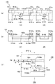
本発明によれば、図1(a)及び図2(a)、(b)に示すように、連続繊維の強化繊維にマトリクス樹脂が含浸された連続強化繊維プリプレグ11と、所定の繊維長さとされる短繊維の強化繊維が所定量配合された短繊維強化樹脂12とを有する繊維強化プラスチック材10が使用される。この繊維強化プラスチック材10は、図1(a)に示すように、金型100(例えば、内金型101及び外金型102)にて1回のプレス成形を行い、その時のプレス圧力によって短繊維強化樹脂12を流動させ、それによって、図1(b)に示すように、連続繊維強化プラスチック層(連続繊維層)11A及び短繊維強化プラスチック層(短繊維層)12Aの積層体から成るシェル1Aと、短繊維強化プラスチック層12Aからなる立体的添加物2Aとを備えた立体添加物付き繊維強化プラスチック成形体1を成形する。
According to the present invention, as shown in FIGS. 1 (a) and 2 (a), (b), a continuous reinforcing fiber prepreg 11 in which a reinforcing fiber of continuous fibers is impregnated with a matrix resin, a predetermined fiber length, A fiber reinforced
更に説明すると、連続強化繊維プリプレグ11は、一方向或いは織物とされる強化繊維に熱可塑性樹脂或いは熱硬化性樹脂が含浸された一方向或いは織物の連続強化繊維プリプレグとされる。
More specifically, the continuous reinforcing
強化繊維としては、炭素繊維が最も好ましいが、その他、種々の繊維を使用し得る。例えば、強化繊維としては、炭素繊維の他に、ガラス繊維、バサルト繊維;ボロン繊維、チタン繊維、スチール繊維などの金属繊維;更には、アラミド、PBO(ポリパラフェニレンベンズビスオキサゾール)、ポリアミド、ポリアリレート、ポリエステルなどの有機繊維;が単独で、又は、複数種混入してハイブリッドにて使用することができる。 As the reinforcing fiber, carbon fiber is most preferable, but various other fibers can be used. For example, as the reinforcing fiber, in addition to carbon fiber, glass fiber, basalt fiber; metal fiber such as boron fiber, titanium fiber, steel fiber; and further, aramid, PBO (polyparaphenylene benzbisoxazole), polyamide, poly Organic fibers such as arylate and polyester can be used alone or in a mixture of plural kinds.
また、樹脂としては、熱硬化性樹脂又は熱可塑性樹脂を使用することができ、熱硬化性樹脂としては、常温硬化型或は熱硬化型のエポキシ樹脂、ビニールエステル樹脂、不飽和ポリエステル樹脂、又はフェノール樹脂などが好適に使用され、又、熱可塑性樹脂としては、ポリカーボネイト樹脂、ポリエーテルイミド樹脂、ポリエーテルエーテルケトン樹脂、ポリエーテルケトンケトン樹脂、ポリフェニレンサルファイド樹脂、アクリル樹脂、ポリウレタン樹脂、ポリプロピレン樹脂、ABS樹脂、ナイロン、ビニロンなどが好適に使用可能である。 Further, as the resin, a thermosetting resin or a thermoplastic resin can be used, and as the thermosetting resin, a room temperature curable type or a thermosetting type epoxy resin, a vinyl ester resin, an unsaturated polyester resin, or Phenol resin and the like are preferably used, and as the thermoplastic resin, polycarbonate resin, polyetherimide resin, polyether ether ketone resin, polyether ketone ketone resin, polyphenylene sulfide resin, acrylic resin, polyurethane resin, polypropylene resin, ABS resin, nylon, vinylon and the like can be suitably used.
連続強化繊維プリプレグ11は、強化繊維を一方向に引き揃えて形成された強化繊維シートに樹脂を含浸させて形成したUD形状のプリプレグか、或いは、強化繊維を織成して形成された平織り、綾織り、朱子織り、などの織物に樹脂を含浸させて形成したクロスプリプレグとされる。樹脂含浸量は、30〜70wt%、好ましくは、40〜60wt%とされる。
The continuous reinforcing
一方、本発明によれば、短繊維強化樹脂12は、強化繊維と樹脂とを含み、強化繊維は繊維長さが0.01〜2.0mm(0.01mm以上、2.0mm以下)の長さの短繊維とされ、樹脂は熱可塑性樹脂或いは熱硬化性樹脂とされる。短繊維強化樹脂12において、強化繊維は、5〜50wt%の配合量にて含まれている。短繊維強化樹脂12は、強化繊維がランダムに配向されたシート状(図2(b))、フレーク状或いはペレット状(図2(a))とされる。
On the other hand, according to the present invention, the short fiber reinforced
本発明にて、上述のように、短繊維強化樹脂12に配合される強化繊維は繊維長さが0.01〜2.0mmの長さの短繊維とされるが、繊維が3mm以上では、細かなリブ構造や、高さの高い立体構造の立体的添加物を成形すると、樹脂の流動性が悪化して微細構造の形成が難しく、十分な高さの立体構造の成形が難しい。繊維長さが0.01未満では、短繊維強化樹脂12としての十分な強度を得ることができない。
In the present invention, as described above, the reinforcing fiber blended in the short fiber reinforced
また、強化繊維は、5〜50wt%(5wt%以上、50wt%以下)の配合量にて含まれているが、含有量が50wt%を超えると、やはり樹脂の流動性が悪化して、微細構造の形成が難しく、十分な高さの立体構造の成形が難しい。また、含有量が5wt%未満では、固化後の熱収縮によって構造体に歪みが生じることがあり、樹脂中に繊維が5wt%以上含まれることが必要である。好ましくは、繊維長さは0.3〜1.0mm、繊維の配合量は、5〜30wt%である。 Further, the reinforcing fiber is contained in a blending amount of 5 to 50 wt% (5 wt% or more and 50 wt% or less), but if the content exceeds 50 wt%, the fluidity of the resin is deteriorated and the fineness is reduced. It is difficult to form a structure, and it is difficult to form a three-dimensional structure with a sufficient height. If the content is less than 5 wt%, the structure may be distorted by heat shrinkage after solidification, and the resin needs to contain 5 wt% or more. Preferably, the fiber length is 0.3 to 1.0 mm, and the amount of fiber is 5 to 30 wt%.
短繊維強化樹脂12に使用する強化繊維及び樹脂は、上記連続強化繊維プリプレグ11と同様とし得る。つまり、強化繊維としては、炭素繊維が最も好ましいが、その他、種々の繊維を使用し得る。例えば、強化繊維としては、炭素繊維の他に、ガラス繊維、バサルト繊維;ボロン繊維、チタン繊維、スチール繊維などの金属繊維;更には、アラミド、PBO(ポリパラフェニレンベンズビスオキサゾール)、ポリアミド、ポリアリレート、ポリエステルなどの有機繊維;が単独で、又は、複数種混入してハイブリッドにて使用することができる。
The reinforcing fiber and resin used for the short fiber reinforced
また、樹脂としては、上述のように、熱硬化性樹脂又は熱可塑性樹脂を使用することができ、熱硬化性樹脂としては、常温硬化型或は熱硬化型のエポキシ樹脂、ビニールエステル樹脂、不飽和ポリエステル樹脂、又はフェノール樹脂などが好適に使用され、又、熱可塑性樹脂としては、ポリカーボネイト樹脂、ポリエーテルイミド樹脂、ポリエーテルエーテルケトン樹脂、ポリエーテルケトンケトン樹脂、ポリフェニレンサルファイド樹脂、アクリル樹脂、ポリウレタン樹脂、ポリプロピレン樹脂、ABS樹脂、ナイロン、ビニロンなどが好適に使用可能である。 In addition, as described above, a thermosetting resin or a thermoplastic resin can be used as the resin. As the thermosetting resin, a room temperature curing type or a thermosetting type epoxy resin, a vinyl ester resin, a non-volatile resin, or the like. Saturated polyester resin, phenol resin, or the like is preferably used, and as the thermoplastic resin, polycarbonate resin, polyether imide resin, polyether ether ketone resin, polyether ketone ketone resin, polyphenylene sulfide resin, acrylic resin, polyurethane Resin, polypropylene resin, ABS resin, nylon, vinylon, etc. can be suitably used.
本発明者らは、上述のように、短繊維強化樹脂12と連続強化繊維プリプレグ11とを備えた繊維強化プラスチック材10を1回のプレス成形にて、特に、プレス成形時のプレスの圧力によって短繊維強化樹脂12を流動させ、連続繊維強化プラスチック層(連続繊維層)11A及び短繊維強化樹脂層(短繊維層)12Aの積層体とされるシェル1Aと、短繊維強化樹脂層(短繊維層)12Aによる立体的添加物2Aと、にて構成される繊維強化プラスチック成形体1を好適に成形し得ることを見出した。
As described above, the inventors of the present invention have performed the fiber reinforced
図1(b)に示す繊維強化プラスチック成形体1の一例では、箱形の成形体1の外周の側面壁体及び底面壁体とされるシェル1Aが、連続繊維強化プラスチック層(連続繊維層)11A及び短繊維強化プラスチック層(短繊維層)12Aの積層体とされ、底面壁体に形成された部品取り付け台部及びリブなどが短繊維強化プラスチック層(短繊維層)12Aによる立体的添加物2Aである。
In an example of the fiber reinforced plastic molded body 1 shown in FIG. 1B, the
本発明の成形方法では、プレス成形するときの金型100の内部に圧力をかけることが重要である。
In the molding method of the present invention, it is important to apply pressure to the inside of the
つまり、プレス時の金型100の、即ち、内金型101と外金型102とにて形成される成形空間V(図4(c)参照)の上面のクリアランスCLを小さくすることで、金型100を押し切る直前に、金型上面の成形空間Vの周辺部分が密閉され、内部に圧力がかかる構造にすることが必要である。斯かる構造とすることで、その圧力で短繊維強化樹脂12が流動し、短繊維強化樹脂12が金型内のリブ構造やねじ孔構造、また高さの高い(幅に対して5倍以上の)立体構造部分に緻密に入り込む。
That is, by reducing the clearance CL on the upper surface of the molding space 100 (see FIG. 4C) formed by the
短繊維強化樹脂12中の繊維が長かったり、繊維量が多すぎると、金型内の細部まで樹脂が充填されず、正確な立体構造を得ることが難しい。また、固化後の冷却による収縮で部材が歪まないようにするには、ある程度の繊維量(5〜50wt%)を含む樹脂が好ましい。
If the fibers in the short fiber reinforced
次に、本発明に従って構成される金型100について更に説明する。図4(a)〜(c)には、詳しくは後述するように、本発明の作用効果を立証するための具体例1、2にて使用した金型100(内金型101、外金型102)を示す。
Next, the
図4(a)の(イ)、(ロ)は、それぞれ、上金型(内金型)101の中央縦断面図及び中央横断面図である。また、図4(b)の(イ)、(ロ)は、それぞれ、下金型(外金型)102の中央縦断面図及び中央横断面図である。 (A) and (b) of FIG. 4A are a central longitudinal sectional view and a central transverse sectional view of the upper mold (inner mold) 101, respectively. 4B are (i) and (b), respectively, a central longitudinal sectional view and a central transverse sectional view of the lower mold (outer mold) 102. FIG.
一般的に言えば、外金型102は凹部102Aを備えており、内金型101は外金型102の凹部102Aに嵌り合う凸部101Aを備えている。成形加工時には、内金型101の凸部101Aが外金型102の凹部102Aに組み合わせられ、成形加工状態に配置された時、互いに対向配置されて外金型102と内金型101との間に繊維強化プラスチック成形体1を形成するための成形空間(V)(図4(c)参照)が形成される。実際の成形加工時には、この成形空間Vに本発明に従って構成される繊維強化プラスチック材10が配置され、内金型101と外金型102とにてプレス成形されることとなる。
Generally speaking, the
また、本発明に従った金型100は、図4(a)〜(c)に示すように、内金型101の凸部101A、及び、外金型102の凹部102Aの外周辺エッジ部分には、それぞれ、鍔部分101a、102aが形成されている。この鍔部分101a、102aは、図4(c)に示すように、内金型101及び外金型102が互いに組み合わせられて成形加工状態に配置された時、凸部101A及び凹部102Aにて形成される成形空間Vを閉空間とするべく互いに対向配置される。
4A to 4C, the
鍔部分101a、102aは、内方端部、即ち、成形空間Vの上面から外方へと、幅W101a、W102aが20〜100mm(20mm以上、100mm以下)にて延在している。
The
また、成形される繊維強化プラスチック成形体1の外周辺エッジ部分に形成した鍔部分101a、102aは、実際の成形加工時には密着することはなく、図4(c)に示すように、両金型の鍔部分101a、102aは、所定のクリアランス(間隙)CLを設けて設置される。本発明に従えば、両金型の鍔部分101a、102aにて形成されるクリアランスCLは、成形しようとする繊維強化プラスチック成形体1におけるシェル部分1Aに相当する成形空間Vの空隙、即ち、シェル1Aの板厚(t)(mm)(図3(b)参照)の0.5以上、0.75以下(0.5・t(mm)≦CL≦0.75・t(mm))に調整することが必要である。
Further, the
鍔部分のクリアランスCLを上述のように調整することによって、成形加工時に成形空間Vにプレス圧力を生じさせ、このプレス時の圧力によって、短繊維強化樹脂12を成形空間Vから外周辺エッジ部分へと流動させることができる。
By adjusting the clearance CL of the flange portion as described above, a press pressure is generated in the molding space V during the molding process, and the short fiber reinforced
つまり、本発明によれば、上述のように、金型100(内金型101、外金型102)には幅(W101a、W102a)が20〜100mmの鍔部分101a、102aを設け、外金型(下金型)102と内金型(上金型)101のクリアランスCLは、連続強化繊維プリプレグ11と短繊維強化樹脂12にて成形される成形物のシェル構造部分1Aの厚み(t)に対して、(0.5〜0.75)・t(mm)の範囲に調整される。
That is, according to the present invention, as described above, the mold 100 (the
本発明では、金型100の鍔部分101a、102aは、幅(W101a、W102a)が20〜100mmとされ、該鍔部分内で短繊維含有樹脂を冷え固まらせることによって金型内へとプレス圧力を生じさせてリブ及びボス等の立体添加物を成型させる。鍔部分101a、102aが20mm未満の場合は、鍔部分101a、102a内で樹脂を急速に固まらせることが必要となり、金型温度を低くする必要がある。そのため、金型内の樹脂も十分な流動ができないままプレスト中で硬化してしまい、シェル部板厚(t)などが所定の寸法以上で成形されることとなる。また、良好なリブ構造等ができなくなる虞がある。また、鍔部分101a、102aが100mmを超える場合は、この100mmを超える鍔部分101a、102aに樹脂を流動させて固化させようとすると、そのためには、金型温度を高くする必要がある。これにより、樹脂は十分な流動性を持って鍔部分101a、102aを移動することとなる。そのため、金型内にプレス圧力を保持させるためには樹脂の逃げが多すぎて、プレス圧力を保持させることが困難となる。そのため、プレス中に圧力が逃げ易くなり、良好なリブ構造等が成形できなくなる。
In the present invention, the
また、クリアランスCLが0.5・t(mm)より小さいときは、長繊維基材である連続強化繊維プリプレグ11の厚みと、短繊維強化樹脂12からのはみ出した樹脂がクリアランスCLを埋め尽くしてしまい、所定の厚みまで押し切ることが出来ず、寸法通りに仕上げることが出来ない。また、0.75・t(mm)よりも大きなクリアランスCLを設けると、短繊維強化樹脂12からのはみ出し樹脂で十分クリアランスCLが埋まりきらず、内部の圧力が逃げてしまい平滑な表面に仕上がらない。
In addition, when the clearance CL is smaller than 0.5 · t (mm), the thickness of the continuous reinforcing
鍔部分101a、102aには内側端部(成形空間V)から外方へと、即ち、短繊維強化樹脂12の流動方向へと、少なくとも、幅W101a(W102a)が15〜30mmの範囲に0.1〜20°(0.1°以上、20°以下)の内勾配(θ)をつけて、外側になるほど徐々にクリアランスCLが狭くなるような加工を施すことが好ましい。図4(c)には、勾配(θ)は、外金型102の鍔部分102aに設けるものとして図示されているが、勿論、内金型101の鍔部分101aの側に設けてもよく、或いは、両鍔部分101a、102aの両方に設けてもよい。
In the
上述したように、本発明では、短繊維強化樹脂12及び連続繊維強化プリプレグ11に使用する樹脂は熱可塑性樹脂でも、熱硬化性樹脂でも良いが、短繊維強化樹脂12及び連続繊維強化プリプレグ11に熱可塑性樹脂を使用した場合は、短繊維強化樹脂12及び連続繊維強化プリプレグ11から成る繊維強化プラスチック材10を熱可塑性樹脂の融点より高い温度に予備加熱した後に、樹脂の融点よりも低い温度に調整された金型100にてプレス成形することで成形できる。
As described above, in the present invention, the resin used for the short fiber reinforced
また、短繊維強化樹脂12及び連続繊維強化プリプレグ11に熱硬化性樹脂を使用した場合には、樹脂が硬化する温度より高い温度に金型100を予備加熱熱してから、短繊維強化樹脂12及び連続繊維強化プリプレグ11から成る繊維強化プラスチック材10を該金型100でプレス成形して、硬化終了後に金型100を開放することで成形可能である。
Further, when a thermosetting resin is used for the short fiber reinforced
図2、図3を参照して、本発明の補強方法を更に具体的に説明する。 With reference to FIGS. 2 and 3, the reinforcing method of the present invention will be described more specifically.
(具体例1)
図3に、本具体例にて成形した立体添加物付き繊維強化プラスチック成形体(以下、単に「成形体」という。)1の全体構成を示す。
(Specific example 1)
FIG. 3 shows the overall configuration of a fiber-reinforced plastic molded body with a three-dimensional additive (hereinafter simply referred to as “molded body”) 1 molded in this specific example.
本具体例の成形体1は、外形寸法が、幅(W0)60mm、長さ(L0)100mm、高さ(H0)20mmとされる箱形シェル1Aの内部に、高さ(H)15mmの十文字のリブ構造2Aを有する構造体とされる。シェル1Aの厚さtは1mm、リブ2Aの厚さt2Aは1.5mmとした。
The molded body 1 of this specific example has a height (H) of 15 mm inside a box-shaped
上述したように、本具体例では、図4(a)〜(c)に示す構造の金型100を使用した。
As described above, in this specific example, the
本具体例にて使用した外金型102は、内寸法が、幅(W102)60mm、長さ(L102)100mm、深さ(H102)20mmで、幅(W102a)が25mmとされる鍔102aの付いた鋼製の金型である。出隅部(R102a)は3mmのR加工を施し、入り隅部(R102b)は角形状のままとした。
The
本例にて使用した内金型101は、外寸法が、幅(W101)が58mm、長さ(L101)が98mm、高さ(H101)が19.5mmで、幅(W101a)が25mmとされる鍔101aの付いた鋼製の金型である。また、内金型101には、リブ構造成形のための幅(W101b)が1.5mmで、深さ(H101b)が15mmの溝101bを十文字の形状にて溝加工を施した。内金型101の出隅部(R101a)は2mmのR加工を施し、入り隅部(R101b)は角形状のままとした。
The
更に、外金型102の鍔部分102aは、図4(c)に示すように、内側(即ち、成形空間Vの側)に低くなるように、角度(θ)が少なくとも0.1°となるような傾斜(勾配)が付いており、本例では、角度(θ)が約0.3°とされ、外方端部では内面に比べて高さ(h)が約0.1mm程度高くなっている。また、両鍔部分101a、102aのクリアランスCLは0.5mmとした。
Further, as shown in FIG. 4C, the
本具体例にて使用した材料は以下の通りである。
・連続強化繊維プリプレグ(11)
炭素繊維平織りクロスプリプレグ:Porcher composites製(PIPREG C/PC(商品名)(ポリカーボネイト樹脂の織物プリプレグ/炭素繊維目付け:196g/m2、樹脂含有率:45wt%)
・短繊維強化樹脂(12)
三菱レイヨン製(PC−C−30:商品名)(炭素繊維の短繊維補強ポリカーボネイト樹脂ペレット/炭素繊維長さ:平均0.3mm、炭素繊維含有率:30wt%)
図2に示すように、上記炭素繊維平織りクロスプリプレグ(連続強化繊維プリプレグ)11を幅(W11)170mm、長さ(L11)210mmに切断し、上記樹脂ペレット(短繊維強化樹脂)12を25g、炭素繊維平織りクロスプリプレグ11の中心部になるべく均等になるように乗せ、2辺をバネ付きのクリップで固定して、加熱オーブン中に放置して300℃に加熱した。その後、このようにして得られた繊維強化プラスチック材10を、金型100にセットしてプレスした。金型温度は50〜70℃であった。
The materials used in this specific example are as follows.
・ Continuous reinforcing fiber prepreg (11)
Carbon fiber plain weave cloth prepreg: Porcher composites (PIPREG C / PC (trade name) (polycarbonate resin fabric prepreg / carbon fiber basis weight: 196 g / m 2 , resin content: 45 wt%)
・ Short fiber reinforced resin (12)
Made by Mitsubishi Rayon (PC-C-30: trade name) (carbon fiber short fiber reinforced polycarbonate resin pellet / carbon fiber length: average 0.3 mm, carbon fiber content: 30 wt%)
2, the carbon fiber plain weave cross prepreg (continuous reinforcing fiber prepreg) 11 is cut into a width (W11) of 170 mm and a length (L11) of 210 mm, and the resin pellet (short fiber reinforced resin) 12 is 25 g. The carbon fiber plain
本具体例では、成形体箱形シェル部分1Aの厚み(t)は1mmに対して、鍔部分101a、102aの金型のクリアランスCLは0.5mmとなり、プレスする瞬間に溶融したペレット樹脂が上昇して、鍔部分101a、102aのクリアランスCLを埋め尽くすため、金型内部全体に圧力がかかる形式とした。
In this specific example, the thickness (t) of the molded
この結果、図3(a)、(b)に示すような成形体1を得ることができた。つまり、箱形シェル部分1Aは、外層11Aと内層12Aとを有し、外層11Aは、長繊維の炭素繊維の平織りクロスの炭素繊維強化プラスチック層とされ、内層12Aは強化繊維として短繊維の炭素繊維を含む短繊維強化プラスチック層とされた。また、内部のリブ部2Aは、箱形シェル部分1Aの内層12Aと同じ樹脂材料のみにて成形された。
As a result, a molded body 1 as shown in FIGS. 3A and 3B could be obtained. That is, the box-shaped
シェル1Aの厚み(t)1.0±0.05mmで、中央の十文字リブの高さ(H)15mm、厚み(t2A)1.5mmで、表面性が良好でリブ部の角欠けなどの無い良好な成形品ができた。
The thickness (t) of the
具体例2
本具体例では、連続強化繊維プリプレグ11として、一方向熱可塑性樹脂プリプレグを使用した。このプリプレグ11は、Schappe Techniques製TPFL−UD(商品名)(ナイロン12樹脂の一方向プリプレグ/炭素繊維目付288g/m2、樹脂含有量:68wt%)であった。この一方向熱可塑性プリプレグを縦横2枚積層したものを、具体例1と同じ形状にカットし、具体例1と同じ熱可塑性樹脂ペレット12を同量だけ乗せて、具体例1と同様にプレスした。
Example 2
In this specific example, a unidirectional thermoplastic resin prepreg was used as the continuous reinforcing
その結果、表面性が良好でリブ部の角欠けなどの無い良好な成形品ができた。 As a result, a good molded product having good surface properties and no corner chipping of the rib portion was obtained.
1 添加物付き繊維強化プラスチック成形体
1A シェル
2A 立体添加物
10 繊維強化プラスチック材
11 連続強化繊維プリプレグ
11A 連続繊維強化プラスチック層(連続繊維層)
12 短繊維強化樹脂
12A 短繊維強化プラスチック層(短繊維層)
100 金型
101 上金型(内金型)
101a 鍔部分
102 下金型(外金型)
102a 鍔部分
DESCRIPTION OF SYMBOLS 1 Fiber reinforced plastic molding with an
12 Short fiber reinforced
100
102a heel part
Claims (4)
熱可塑性樹脂或いは熱硬化性樹脂が含浸された一方向或いは織物の連続強化繊維プリプレグと、
を有する繊維強化プラスチック材を、外金型及び内金型を有する金型による1回のプレス成形により、前記連続強化繊維プリプレグと前記短繊維強化樹脂にて成形された連続繊維層と短繊維層の積層体から成るシェルと、前記短繊維強化樹脂にて成形された立体添加物とを有する繊維強化プラスチック成形体を成形する方法であって、
前記外金型及び前記内金型は、互いに組み合わせて成形加工状態に配置された時、互いに対向配置されて前記外金型と前記内金型との間に前記繊維強化プラスチック成形体を形成するための成形空間を形成する鍔部分を有しており、
前記鍔部分は、前記成形空間から外方へと20mm以上、100mm以下にて前記外金型及び前記内金型の外周辺に延在して形成されており、
対向配置された前記両金型の前記鍔部分のクリアランスを、成形しようとする前記繊維強化プラスチック成形体の前記シェルの板厚(tmm)に対して0.5・t(mm)以上、0.75・t(mm)以下に調整することによって、プレスの圧力を生じさせ、このプレスの圧力によって、樹脂を流動させて前記鍔部分のクリアランスに樹脂をはみ出させることを特徴とする立体添加物付き繊維強化プラスチック成形体の成形方法。 A sheet-like, flake-like or pellet-like thermoplastic resin or thermosetting resin in which short fibers having a fiber length of 0.01 mm or more and 2.0 mm or less are randomly oriented at a blending amount of 5 to 50 wt%; Short fiber reinforced resin,
Unidirectional or woven continuous reinforcing fiber prepreg impregnated with thermoplastic resin or thermosetting resin;
A continuous fiber layer and a short fiber layer formed of the continuous reinforcing fiber prepreg and the short fiber reinforced resin by one-time press molding using a mold having an outer mold and an inner mold. A method of molding a fiber-reinforced plastic molded body having a shell made of a laminate of the above and a three-dimensional additive molded with the short fiber-reinforced resin,
When the outer mold and the inner mold are arranged in combination with each other, they are arranged opposite to each other to form the fiber-reinforced plastic molded body between the outer mold and the inner mold. And has a flange portion that forms a molding space for
The flange portion is formed to extend outward from the molding space to the outer periphery of the outer mold and the inner mold at 20 mm or more and 100 mm or less,
The clearance of the flange portions of the two molds arranged to face each other is 0.5 · t (mm) or more with respect to the plate thickness (tmm) of the shell of the fiber-reinforced plastic molding to be molded, and With a three-dimensional additive characterized in that the pressure of the press is generated by adjusting to 75 · t (mm) or less, and the resin flows by the pressure of the press so that the resin protrudes into the clearance of the flange portion. A method for forming a fiber-reinforced plastic molded body.
Priority Applications (1)
| Application Number | Priority Date | Filing Date | Title |
|---|---|---|---|
| JP2012040773A JP5956187B2 (en) | 2012-02-27 | 2012-02-27 | Method for molding fiber reinforced plastic molding with three-dimensional additive |
Applications Claiming Priority (1)
| Application Number | Priority Date | Filing Date | Title |
|---|---|---|---|
| JP2012040773A JP5956187B2 (en) | 2012-02-27 | 2012-02-27 | Method for molding fiber reinforced plastic molding with three-dimensional additive |
Publications (3)
| Publication Number | Publication Date |
|---|---|
| JP2013173334A JP2013173334A (en) | 2013-09-05 |
| JP2013173334A5 JP2013173334A5 (en) | 2015-03-26 |
| JP5956187B2 true JP5956187B2 (en) | 2016-07-27 |
Family
ID=49266727
Family Applications (1)
| Application Number | Title | Priority Date | Filing Date |
|---|---|---|---|
| JP2012040773A Active JP5956187B2 (en) | 2012-02-27 | 2012-02-27 | Method for molding fiber reinforced plastic molding with three-dimensional additive |
Country Status (1)
| Country | Link |
|---|---|
| JP (1) | JP5956187B2 (en) |
Families Citing this family (8)
| Publication number | Priority date | Publication date | Assignee | Title |
|---|---|---|---|---|
| JP6345613B2 (en) * | 2015-02-06 | 2018-06-20 | 住友建機株式会社 | Excavator cover |
| JP6602552B2 (en) * | 2015-04-14 | 2019-11-06 | 国立大学法人岐阜大学 | Manufacturing method of molded body |
| WO2016167232A1 (en) * | 2015-04-16 | 2016-10-20 | 三菱瓦斯化学株式会社 | Method for producing molded article by press molding thermoplastic resin sheet or film |
| JP6190848B2 (en) * | 2015-07-03 | 2017-08-30 | 本田技研工業株式会社 | Manufacturing method of resin products |
| US10889076B2 (en) | 2016-01-08 | 2021-01-12 | Teijin Limited | Method for producing fiber-reinforced resin shaped product |
| JP2019093685A (en) * | 2017-11-28 | 2019-06-20 | 東洋製罐グループホールディングス株式会社 | Fiber-reinforced laminate and method for producing the same |
| US10933598B2 (en) * | 2018-01-23 | 2021-03-02 | The Boeing Company | Fabrication of composite parts having both continuous and chopped fiber components |
| KR20200135782A (en) * | 2018-03-30 | 2020-12-03 | 도레이 카부시키가이샤 | Manufacturing method of molded article |
Family Cites Families (8)
| Publication number | Priority date | Publication date | Assignee | Title |
|---|---|---|---|---|
| JPS56115216A (en) * | 1980-01-24 | 1981-09-10 | Hitachi Chem Co Ltd | Prepreg material and manufacture thereof |
| JPH01232019A (en) * | 1988-03-14 | 1989-09-18 | Chisso Corp | Conductive thermoplastic resin molded material |
| JPH01176520A (en) * | 1988-01-05 | 1989-07-12 | Chisso Corp | Conductive thermoplastic resin molded product |
| JPH05154900A (en) * | 1991-12-09 | 1993-06-22 | Teijin Ltd | Curved-face molded piece and production thereof |
| JP2000043067A (en) * | 1998-07-30 | 2000-02-15 | Ikeda Bussan Co Ltd | Molding of interior material for vehicle |
| JP4220805B2 (en) * | 2003-03-03 | 2009-02-04 | 本田技研工業株式会社 | Manufacturing method for vehicle hood made of fiber reinforced composite material |
| JP4294038B2 (en) * | 2006-06-13 | 2009-07-08 | 株式会社ギンポーパック | Press forming equipment |
| JP5332227B2 (en) * | 2008-02-20 | 2013-11-06 | 東レ株式会社 | Press molding method and molded body |
-
2012
- 2012-02-27 JP JP2012040773A patent/JP5956187B2/en active Active
Also Published As
| Publication number | Publication date |
|---|---|
| JP2013173334A (en) | 2013-09-05 |
Similar Documents
| Publication | Publication Date | Title |
|---|---|---|
| JP5956187B2 (en) | Method for molding fiber reinforced plastic molding with three-dimensional additive | |
| JP6020826B2 (en) | Fiber-reinforced composite material molding method and fiber-reinforced composite material molding apparatus | |
| US11911933B2 (en) | Molded body and manufacturing method therefor | |
| US20130078439A1 (en) | Structure of fiber-reinforced composite material-made component part, and production method for the component part | |
| US10821683B2 (en) | Method for molding flame-retardant bending beam integrated with three-dimensional nylon air duct and production mould thereof | |
| CN102869487A (en) | Method for producing component from fibre-reinforced material | |
| EP3042753B1 (en) | Production method for fiber-reinforced components | |
| CN109715361A (en) | The forming method and composite material of composite material | |
| JP2008246981A (en) | Manufacturing method of fiber-reinforced composite material | |
| JP2013173334A5 (en) | ||
| JP6567255B2 (en) | Fiber reinforced thermoplastic resin molding | |
| CN108136685B (en) | Method for producing fiber-reinforced resin structure, system for producing fiber-reinforced resin structure, and fiber-reinforced resin structure | |
| JP7151272B2 (en) | Method for manufacturing fiber-reinforced plastic molded product | |
| KR20200080390A (en) | 3-dimensional printing method and 3-dimensional printing product by the same | |
| KR20140050779A (en) | Method for forming fiber reinforced plastic composite | |
| KR102349669B1 (en) | Forming method of fiber reinforced plastic material | |
| JP2010221489A (en) | Rtm molding method | |
| JP6776944B2 (en) | Manufacturing method of resin molded product | |
| JP2010076356A (en) | Preform, and molding method for fiber-reinforced plastic | |
| JP2021041634A (en) | Method for molding laminated composite sheet comprising fiber reinforced resin sheet and resin foamed sheet | |
| JP6786989B2 (en) | Composite material molding method | |
| JP7139296B2 (en) | Fiber-reinforced resin composite molding and method for producing the same | |
| JP6712430B1 (en) | Method for producing thermoplastic fiber-reinforced resin molded product | |
| KR102291931B1 (en) | Manufacturing method for molded article using fiber reinforcerd plastic waste comprising thermosetting plastics and molded article using the same | |
| JP7220004B2 (en) | Fiber-reinforced resin composite molding and method for producing the same |
Legal Events
| Date | Code | Title | Description |
|---|---|---|---|
| A521 | Request for written amendment filed |
Free format text: JAPANESE INTERMEDIATE CODE: A523 Effective date: 20150205 |
|
| A621 | Written request for application examination |
Free format text: JAPANESE INTERMEDIATE CODE: A621 Effective date: 20150205 |
|
| A977 | Report on retrieval |
Free format text: JAPANESE INTERMEDIATE CODE: A971007 Effective date: 20150925 |
|
| A131 | Notification of reasons for refusal |
Free format text: JAPANESE INTERMEDIATE CODE: A131 Effective date: 20151006 |
|
| A521 | Request for written amendment filed |
Free format text: JAPANESE INTERMEDIATE CODE: A523 Effective date: 20151207 |
|
| A131 | Notification of reasons for refusal |
Free format text: JAPANESE INTERMEDIATE CODE: A131 Effective date: 20160426 |
|
| A521 | Request for written amendment filed |
Free format text: JAPANESE INTERMEDIATE CODE: A523 Effective date: 20160530 |
|
| TRDD | Decision of grant or rejection written | ||
| A01 | Written decision to grant a patent or to grant a registration (utility model) |
Free format text: JAPANESE INTERMEDIATE CODE: A01 Effective date: 20160614 |
|
| A61 | First payment of annual fees (during grant procedure) |
Free format text: JAPANESE INTERMEDIATE CODE: A61 Effective date: 20160616 |
|
| R150 | Certificate of patent or registration of utility model |
Ref document number: 5956187 Country of ref document: JP Free format text: JAPANESE INTERMEDIATE CODE: R150 |
|
| S111 | Request for change of ownership or part of ownership |
Free format text: JAPANESE INTERMEDIATE CODE: R313115 |
|
| R360 | Written notification for declining of transfer of rights |
Free format text: JAPANESE INTERMEDIATE CODE: R360 |
|
| R360 | Written notification for declining of transfer of rights |
Free format text: JAPANESE INTERMEDIATE CODE: R360 |
|
| R371 | Transfer withdrawn |
Free format text: JAPANESE INTERMEDIATE CODE: R371 |
|
| S111 | Request for change of ownership or part of ownership |
Free format text: JAPANESE INTERMEDIATE CODE: R313115 |
|
| R350 | Written notification of registration of transfer |
Free format text: JAPANESE INTERMEDIATE CODE: R350 |
|
| R250 | Receipt of annual fees |
Free format text: JAPANESE INTERMEDIATE CODE: R250 |
|
| S531 | Written request for registration of change of domicile |
Free format text: JAPANESE INTERMEDIATE CODE: R313531 |
|
| R350 | Written notification of registration of transfer |
Free format text: JAPANESE INTERMEDIATE CODE: R350 |
|
| R250 | Receipt of annual fees |
Free format text: JAPANESE INTERMEDIATE CODE: R250 |
|
| R250 | Receipt of annual fees |
Free format text: JAPANESE INTERMEDIATE CODE: R250 |
|
| R250 | Receipt of annual fees |
Free format text: JAPANESE INTERMEDIATE CODE: R250 |
|
| R250 | Receipt of annual fees |
Free format text: JAPANESE INTERMEDIATE CODE: R250 |
|
| R250 | Receipt of annual fees |
Free format text: JAPANESE INTERMEDIATE CODE: R250 |