JP5955862B2 - Immersive audio rendering system - Google Patents
Immersive audio rendering system Download PDFInfo
- Publication number
- JP5955862B2 JP5955862B2 JP2013548464A JP2013548464A JP5955862B2 JP 5955862 B2 JP5955862 B2 JP 5955862B2 JP 2013548464 A JP2013548464 A JP 2013548464A JP 2013548464 A JP2013548464 A JP 2013548464A JP 5955862 B2 JP5955862 B2 JP 5955862B2
- Authority
- JP
- Japan
- Prior art keywords
- depth
- signal
- signals
- audio signals
- audio
- Prior art date
- Legal status (The legal status is an assumption and is not a legal conclusion. Google has not performed a legal analysis and makes no representation as to the accuracy of the status listed.)
- Active
Links
Images


Classifications
-
- H—ELECTRICITY
- H04—ELECTRIC COMMUNICATION TECHNIQUE
- H04S—STEREOPHONIC SYSTEMS
- H04S1/00—Two-channel systems
- H04S1/002—Non-adaptive circuits, e.g. manually adjustable or static, for enhancing the sound image or the spatial distribution
-
- H—ELECTRICITY
- H04—ELECTRIC COMMUNICATION TECHNIQUE
- H04R—LOUDSPEAKERS, MICROPHONES, GRAMOPHONE PICK-UPS OR LIKE ACOUSTIC ELECTROMECHANICAL TRANSDUCERS; DEAF-AID SETS; PUBLIC ADDRESS SYSTEMS
- H04R5/00—Stereophonic arrangements
-
- H—ELECTRICITY
- H04—ELECTRIC COMMUNICATION TECHNIQUE
- H04S—STEREOPHONIC SYSTEMS
- H04S7/00—Indicating arrangements; Control arrangements, e.g. balance control
- H04S7/30—Control circuits for electronic adaptation of the sound field
-
- H—ELECTRICITY
- H04—ELECTRIC COMMUNICATION TECHNIQUE
- H04S—STEREOPHONIC SYSTEMS
- H04S2400/00—Details of stereophonic systems covered by H04S but not provided for in its groups
- H04S2400/01—Multi-channel, i.e. more than two input channels, sound reproduction with two speakers wherein the multi-channel information is substantially preserved
-
- H—ELECTRICITY
- H04—ELECTRIC COMMUNICATION TECHNIQUE
- H04S—STEREOPHONIC SYSTEMS
- H04S2400/00—Details of stereophonic systems covered by H04S but not provided for in its groups
- H04S2400/07—Generation or adaptation of the Low Frequency Effect [LFE] channel, e.g. distribution or signal processing
-
- H—ELECTRICITY
- H04—ELECTRIC COMMUNICATION TECHNIQUE
- H04S—STEREOPHONIC SYSTEMS
- H04S2400/00—Details of stereophonic systems covered by H04S but not provided for in its groups
- H04S2400/11—Positioning of individual sound objects, e.g. moving airplane, within a sound field
-
- H—ELECTRICITY
- H04—ELECTRIC COMMUNICATION TECHNIQUE
- H04S—STEREOPHONIC SYSTEMS
- H04S2420/00—Techniques used stereophonic systems covered by H04S but not provided for in its groups
- H04S2420/01—Enhancing the perception of the sound image or of the spatial distribution using head related transfer functions [HRTF's] or equivalents thereof, e.g. interaural time difference [ITD] or interaural level difference [ILD]
-
- H—ELECTRICITY
- H04—ELECTRIC COMMUNICATION TECHNIQUE
- H04S—STEREOPHONIC SYSTEMS
- H04S7/00—Indicating arrangements; Control arrangements, e.g. balance control
- H04S7/30—Control circuits for electronic adaptation of the sound field
- H04S7/302—Electronic adaptation of stereophonic sound system to listener position or orientation
Landscapes
- Physics & Mathematics (AREA)
- Engineering & Computer Science (AREA)
- Acoustics & Sound (AREA)
- Signal Processing (AREA)
- Stereophonic System (AREA)
Description
関連出願
本出願は、米国特許法第119条(e)の下で、「没入型オーディオ・レンダリング・システム(Immersive Audio Rendering System)」と題する、2011年1月4日に出願された米国特許仮出願第61/429,600号明細書の優先権を主張し、この出願の開示は、全体が参照により本明細書に組み入れられる。
RELATED APPLICATIONS This application is a US patent provisional application filed January 4, 2011 entitled “Immersive Audio Rendering System” under 35 USC 119 (e). Claiming priority of application 61 / 429,600, the disclosure of which is incorporated herein by reference in its entirety.
技術的能力およびユーザの好みの増大が、広範なオーディオ録音および再生システムをまねいた。オーディオシステムは、別個の左および右の録音/再生チャンネルを有する、より簡単なステレオシステムを越えて、通例サラウンド・サウンド・システムと呼ばれるものに発展した。サラウンド・サウンド・システムは、一般に、リスナの周囲に配置された、一般にリスナの背後に位置する複数の音源を含む、複数の空間的場所から発生する、または発生するように思われる複数の音源を提供することにより、リスナに対してより臨場感のある再生体験を提供するように設計される。 Increased technical capabilities and user preferences have imitated a wide range of audio recording and playback systems. Audio systems have evolved beyond what is called simple surround sound systems, beyond simpler stereo systems with separate left and right recording / playback channels. Surround sound systems typically generate multiple sound sources that originate from, or appear to generate from, multiple spatial locations, including multiple sound sources that are generally located behind the listener and are located around the listener. By providing, it is designed to provide a more realistic reproduction experience for listeners.
サラウンド・サウンド・システムは、しばしば、一般にリスナの前にサウンドを生成するように適合されたセンターチャンネル、少なくとも1つの左チャンネル、および少なくとも1つの右チャンネルを含む。サラウンド・サウンド・システムはまた、一般にリスナの背後にあるサウンドの生成のために適合された少なくとも1つの左サラウンド音源および少なくとも1つの右サラウンド音源を一般に含む。サラウンド・サウンド・システムはまた、低周波サウンドの再生を改善するために、ときどきサブウーファチャンネルと呼ばれる低域効果音(low frequency effect、LFE)チャンネルを含むことができる。特定の一例として、センターチャンネル、左フロントチャンネル、右フロントチャンネル、左サラウンドチャンネル、右サラウンドチャンネル、およびLFEチャンネルを有するサラウンド・サウンド・システムを、5.1サラウンドシステムと呼ぶことができる。ピリオドの前の数字5は、存在するバス以外のスピーカ数を示し、ピリオドの後の数字1は、サブウーファの存在を示す。
Surround sound systems often include a center channel, at least one left channel, and at least one right channel that are generally adapted to generate sound before the listener. The surround sound system also generally includes at least one left surround sound source and at least one right surround sound source that are generally adapted for the generation of sound behind the listener. The surround sound system can also include a low frequency effect (LFE) channel, sometimes referred to as a subwoofer channel, to improve the reproduction of low frequency sound. As a specific example, a surround sound system having a center channel, a left front channel, a right front channel, a left surround channel, a right surround channel, and an LFE channel can be referred to as a 5.1 surround system. The number 5 before the period indicates the number of speakers other than the existing buses, and the
開示を要約するために、本発明のある種の態様、利点、および新規の特徴が本明細書で説明された。本明細書で開示される本発明の任意の特定の実施形態に従ってこのような利点すべてを必ずしも達成することができるわけではないことを理解されたい。したがって、本明細書で教示または示唆することができるような他の利点を必ずしも達成することなく、本明細書で教示されるような1つの利点または利点のグループを達成する、または最適化するやり方で、本明細書で開示される本発明を具体化する、または遂行することができる。 For purposes of summarizing the disclosure, certain aspects, advantages, and novel features of the invention have been described herein. It should be understood that not all such advantages may be achieved in accordance with any particular embodiment of the invention disclosed herein. Thus, how to achieve or optimize one advantage or group of advantages as taught herein without necessarily achieving other advantages as may be taught or suggested herein. Thus, the invention disclosed herein can be embodied or carried out.
ある種の実施形態では、オーディオ出力信号に深度をレンダリングする方法が、複数のオーディオ信号を受信することと、第1の時間に複数のオーディオ信号から第1の深度ステアリング情報を識別することと、第2の時間に複数のオーディオ信号から次の深度ステアリング情報を識別することとを含む。さらに、方法は第1の深度ステアリング情報に、少なくとも部分的に依存する第1の量により複数のオーディオ信号を、1つまたは複数のプロセッサにより脱相関(decorrelate)して、第1の脱相関された複数のオーディオ信号を作り出すことを含むことができる。方法は、第1の脱相関された複数のオーディオ信号を、再生のためにリスナに出力することをさらに含んでもよい。さらに、方法は、前記出力することの次に、第1の量と異なる第2の量により複数のオーディオ信号を脱相関することを含むことができ、第2の量は、第2の脱相関された複数のオーディオ信号を作り出すために、次の深度ステアリング情報に少なくとも部分的に依存することができる。さらに、方法は、第2の脱相関された複数のオーディオ信号を、再生のためにリスナに出力することを含むことができる。 In certain embodiments, a method of rendering depth in an audio output signal receives a plurality of audio signals and identifying first depth steering information from the plurality of audio signals at a first time; Identifying next depth steering information from the plurality of audio signals at a second time. Furthermore, the method in the first depth steering information, at least a plurality of audio signals by a first amount of partially dependent, and de-correlation by one or more processors (decorrelate), first decorrelation Producing a plurality of rendered audio signals. The method may further include outputting the first decorrelated audio signals to a listener for playback. Further, the method can include decorrelating a plurality of audio signals with a second quantity that is different from the first quantity, following the outputting, wherein the second quantity is a second decorrelation value. To at least partially rely on subsequent depth steering information to produce a plurality of audio signals. Further, the method can include outputting the second decorrelated plurality of audio signals to a listener for playback.
他の実施形態では、オーディオ出力信号に深度をレンダリングする方法が、複数のオーディオ信号を受信することと、時間とともに変化する深度ステアリング情報を識別することと、深度ステアリング情報に少なくとも部分的に基づき、複数のオーディオ信号を時間とともに動的に脱相関して、複数の脱導相関された信号を作り出すことと、複数の脱相関されたオーディオ信号を再生のためにリスナに出力することとを含むことができる。少なくとも前記脱相関、または本方法の任意の他のサブセットを、電子回路ハードウェアにより実現することができる。 In another embodiment, a method for rendering depth in an audio output signal is based at least in part on receiving multiple audio signals, identifying depth steering information that varies over time, and depth steering information. a plurality of audio signals to dynamically decorrelation over time, includes the creation of multiple Datsushirube correlated signal, and outputting the listener a plurality of de-correlation audio signals for reproduction be able to. At least said de-correlation, or any other subset of the present process, can be realized by an electronic circuit hardware.
オーディオ出力信号に深度をレンダリングするシステムが、いくつかの実施形態では、2つ以上のオーディオ信号を受信することができ、かつ2つ以上のオーディオ信号に関連する深度情報を識別することができる深度推定器と、1つまたは複数のプロセッサを備える深度レンダラとを含むことができる。深度レンダラは、深度情報に少なくとも部分的に基づき、2つ以上のオーディオ信号を時間とともに動的に脱相関して、複数の脱相関されたオーディオ信号を作り出し、かつ複数の脱相関されたオーディオ信号を出力することができる(たとえば、再生のためにリスナに、および/または他のオーディオ処理構成要素へ出力するため)。 A system that renders depth in an audio output signal can, in some embodiments, receive more than one audio signal and identify depth information associated with the more than one audio signal. An estimator and a depth renderer comprising one or more processors may be included. Depth renderer, based at least in part on the depth information, the two or more audio signals to dynamically Datsuso Seki over time, creating a plurality of decorrelated audio signals, and has a plurality of decorrelated audio The signal can be output (eg, for output to a listener for playback and / or to other audio processing components).
オーディオ出力信号に深度をレンダリングする方法のさまざまな実施形態が、2つ以上のオーディオ信号を有する入力オーディオを受信することと、時間とともに変化してもよい、入力オーディオに関連する深度情報を推定することと、1つまたは複数のプロセッサにより、推定された深度情報に基づきオーディオを動的に拡張することとを含む。この拡張することは、時間とともに起こる深度情報の変動に基づき動的に変わることができる。さらに、方法は、拡張されたオーディオを出力することを含むことができる。 Various embodiments of a method for rendering depth in an audio output signal receive input audio having more than one audio signal and estimate depth information associated with the input audio that may change over time And dynamically expanding the audio based on the estimated depth information by one or more processors. This expansion can change dynamically based on variations in depth information that occur over time. Further, the method can include outputting enhanced audio.
オーディオ出力信号に深度をレンダリングするシステムが、いくつかの実施形態では、2つ以上のオーディオ信号を有する入力オーディオを受信することができ、かつ入力オーディオに関連する深度情報を推定することができる深度推定器と、1つまたは複数のプロセッサを有する拡張構成要素とを含むことができる。拡張構成要素は、推定された深度情報に基づき、オーディオを動的に拡張することができる。この拡張は、時間とともに起こる深度情報の変動に基づき動的に変わることができる。 A depth rendering system for rendering an audio output signal can in some embodiments receive input audio having more than one audio signal and estimate depth information associated with the input audio. An estimator and an extension component having one or more processors can be included. The extension component can dynamically extend the audio based on the estimated depth information. This expansion can change dynamically based on variations in depth information that occur over time.
ある種の実施形態では、オーディオ信号に適用された遠近感拡張を変調する方法が、リスナを基準にして音源の空間的位置に関する情報をそれぞれ有する左および右のオーディオ信号を受信することを含む。方法はまた、左および右のオーディオ信号の差情報を計算することと、左および右のオーディオ信号の差情報に少なくとも1つの遠近感フィルタを適用して、左および右の出力信号をもたらすこと、および左および右の出力信号にゲインを適用することと含みことができる。このゲインの値は、計算された差情報に少なくとも一部は基づくことができる。ゲインを少なくとも前記適用すること(または方法全体または方法のサブセット)は、1つまたは複数のプロセッサにより実施される。 In certain embodiments, a method of modulating a perspective extension applied to an audio signal includes receiving left and right audio signals, each having information about the spatial location of the sound source relative to the listener. The method also calculates difference information between the left and right audio signals and applies at least one perspective filter to the difference information between the left and right audio signals to provide left and right output signals; And applying gain to the left and right output signals. This gain value may be based at least in part on the calculated difference information. At least the application of gain (or the entire method or a subset of the method) is performed by one or more processors.
いくつかの実施形態では、オーディオ信号に適用される遠近感拡張を変調するシステムが、少なくとも、リスナを基準にして音源の空間的位置に関する情報をそれぞれ有する左および右のオーディオ信号を受信し、左および右のオーディオ信号から差信号を得ることにより、複数のオーディオ信号を解析することができる信号解析構成要素を含む。システムはまた、1つまたは複数の物理的プロセッサを有するサラウンドプロセッサを含むことができる。サラウンドプロセッサは、少なくとも1つの遠近感フィルタを差信号に適用して、左および右の出力信号をもたらすことができ、計算された差分情報に少なくとも一部は基づき、少なくとも1つの遠近感フィルタの出力を変調することができる。 In some embodiments, a system for modulating a perspective extension applied to an audio signal receives at least left and right audio signals each having information about a spatial location of a sound source relative to a listener, And a signal analysis component capable of analyzing a plurality of audio signals by obtaining a difference signal from the right audio signal. The system can also include a surround processor having one or more physical processors. The surround processor can apply at least one perspective filter to the difference signal to provide left and right output signals, and based at least in part on the calculated difference information, the output of the at least one perspective filter Can be modulated.
ある種の実施形態では、中に記憶された複数の命令を有する非一時的な物理的コンピュータ記憶装置が、オーディオ信号に適用された遠近感拡張を変調するための複数の動作を1つまたは複数のプロセッサで実現することができる。これらの動作は、リスナを基準にして音源の空間的位置に関する情報をそれぞれ有する左および右のオーディオ信号を受信することと、左および右のオーディオ信号の差情報を計算することと、左および右のオーディオ信号の各々に少なくとも1つの遠近感フィルタを適用して、左および右の出力信号をもたらすことと、計算された差情報に少なくとも一部は基づき、少なくとも1つの遠近感フィルタの前記適用を変調することとを含むことができる。 In certain embodiments, a non-transitory physical computer storage device having a plurality of instructions stored therein has one or more operations for modulating a perspective extension applied to an audio signal. It can be realized with a processor. These operations include receiving left and right audio signals with information about the spatial position of the sound source relative to the listener, calculating difference information between the left and right audio signals, and left and right Applying at least one perspective filter to each of the audio signals to provide left and right output signals, and based on the calculated difference information at least in part, said application of at least one perspective filter. Modulating.
オーディオ信号に適用された遠近感拡張を変調するシステムが、いくつかの実施形態では、リスナを基準にして音源の空間的位置に関する情報をそれぞれ有する左および右のオーディオ信号を受信するための手段と、左および右のオーディオ信号の差情報を計算するための手段と、左および右のオーディオ信号の各々に少なくとも1つの遠近感フィルタを適用して、左および右の出力信号をもたらすための手段と、計算された差情報に少なくとも一部は基づき、少なくとも1つの遠近感フィルタの前記適用を変調するための手段とを含む。 A system for modulating a perspective extension applied to an audio signal, in some embodiments, means for receiving left and right audio signals each having information about the spatial location of a sound source relative to a listener; Means for calculating difference information between the left and right audio signals and means for applying at least one perspective filter to each of the left and right audio signals to provide a left and right output signal; Means for modulating the application of at least one perspective filter based at least in part on the calculated difference information.
図面全体を通して、参照される要素間の対応を示すために、参照番号を再利用することができる。図面は、本発明の範囲を限定するためではなく、本明細書で説明される本発明の実施形態を例示するために提供される。 Throughout the drawings, reference numbers can be reused to indicate correspondence between referenced elements. The drawings are provided to illustrate the embodiments of the invention described herein, not to limit the scope of the invention.
I.序文
サラウンド・サウンド・システムは、リスナの周囲に位置する複数のスピーカからサウンドを投射することにより没入型オーディオ環境を生み出そうとする。サラウンド・サウンド・システムは、典型的には、ステレオシステムなどの、より少ないスピーカを有するシステムよりも、オーディオファンに、より好まれる。しかしながら、ステレオシステムはしばしば、より少ないスピーカを有するためにより安価であり、したがって、ステレオスピーカを使ってサラウンドサウンド効果を近似するために、多くの取り組みが行われた。このような取り組みにもかかわらず、3つ以上のスピーカを有するサラウンドサウンド効果は、ステレオシステムよりしばしば没入できる。
I. Preface Surround sound systems attempt to create an immersive audio environment by projecting sound from multiple speakers located around the listener. Surround sound systems are typically preferred by audio fans over systems with fewer speakers, such as stereo systems. However, stereo systems are often cheaper because they have fewer speakers, and therefore much work has been done to approximate the surround sound effect using stereo speakers. Despite this approach, surround sound effects with more than two speakers are more immersive than stereo systems.
この開示は、ステレオスピーカを利用して、多分他のスピーカ構成の間の没入型効果を達成する深度処理システムについて説明する。深度処理システムは、有利には、位相および/振幅の情報を操作して、リスナの正中面に沿ってオーディをレンダリングすることができ、それにより、リスナに対して変わる深度でオーディオをレンダリングする。一実施形態では、深度処理システムは、左および右のステレオ入力信号を解析して、時間とともに変化してもよい深度を推測する。深度処理システムは、次いで、複数のオーディオ信号間の位相および/または振幅の脱相関を時間とともに変えることができ、それにより、没入型深度効果を生み出す。 This disclosure describes a depth processing system that utilizes stereo speakers to achieve an immersive effect, perhaps between other speaker configurations. The depth processing system can advantageously manipulate phase and / or amplitude information to render audio along the midline of the listener, thereby rendering audio at varying depths relative to the listener. In one embodiment, the depth processing system analyzes the left and right stereo input signals to infer a depth that may change over time. Depth processing system, then it is possible to change the phase and / or de-phases function of the amplitude between a plurality of audio signals with time, thereby creating an immersive depth effect.
電子デバイス、たとえば電話機、テレビ、ラップトップ、他のコンピュータ、携帯型メディアプレーヤ、カー・ステレオ・システムなどで、本明細書で説明するオーディオシステムの特徴を実現して、2つ以上のスピーカを使用する没入型オーディオ効果を生み出すことができる。 Electronic devices such as telephones, televisions, laptops, other computers, portable media players, car stereo systems, etc. implement the features of the audio system described herein and use two or more speakers Can produce immersive audio effects.
II.オーディオ深度推定およびレンダリングの実施形態
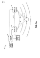
図1Aは、没入型オーディオ環境100の一実施形態を示す。図示する没入型オーディオ環境100は、2(または3つ以上)チャンネルオーディオ入力を受信し、かつ左および右のスピーカ112、114への2チャンネルオーディオ出力を、サブウーファ116への任意選択の第3の出力とともに作り出す深度処理システム110を含む。有利には、ある種の実施形態では、深度処理システム110は、2チャンネルオーディオ入力信号を解析して、これらの信号に関する深度情報を推定または推測する。この深度情報を使用して、深度処理システム110は、複数のオーディオ入力信号を調節して、左および右のステレオスピーカ112、114に提供される複数のオーディ出力信号に深度の感覚を生み出すことができる。その結果、左および右のスピーカは、リスナ102に対して没入型音場(曲線で示す)を出力することができる。この没入型音場は、リスナ102に対して深度の感覚を生み出すことができる。
II. Audio Depth Estimation and Rendering Embodiment FIG. 1A illustrates one embodiment of an
深度処理システム110により提供される没入型音場効果は、サラウンド・サウンド・スピーカの没入型効果より効果的に機能することができる。したがって、サラウンドシステムの近似と考えるのではなく、深度処理システム110は、既存のサラウンドシステムに対して利益を提供することができる。ある種の実施形態で提供される1つの利点が、没入型音場効果は、スイートスポットとは比較的に無関係とすることができ、リスニング空間全体に没入型効果を提供することである。しかしながら、いくつかの実施形態では、スピーカ間にほぼ等距離に、および2つのスピーカとともに実質的に正三角形を形成する角度で(破線104で示す)リスナ2を配置することにより、強められた没入型効果を達成することができる。
The immersive sound field effect provided by the
図1Bは、深度レンダリングの実施形態に関係のあるリスニング環境150の態様を示す。リスナ102に関連する2つの幾何学的平面160、170の関連においてリスナ102を示す。これらの平面は、正中(median)面または矢状(saggital)面160、および額(frontal)面または冠状(coronal)面170を含む。有益には、いくつかの実施形態では、リスナ102の正中面に沿ってオーディオをレンダリングすることにより、3次元オーディオ効果を得ることができる。
FIG. 1B illustrates aspects of the listening
参考に、リスナ102の隣に一例の座標系180を示す。この座標系180では、正中面160はy−z平面内にあり、冠状面170はx−y平面内にある。x−y平面はまた、リスナ102に向く2つのステレオスピーカ間に形成されてもよい平面に対応する。座標系180のz軸は、このような平面に対する法線とすることができる。いくつかの実施形態では、正中面160に沿ってオーディオをレンダリングすることは、座標系180のz軸に沿ってオーディオをレンダリングすることであると考えることができる。したがって、たとえば、正中面に沿って深度処理システム110により深度効果をレンダリングすることができ、その結果、一部のサウンドが、正中面160に沿ってリスナにより近く聞こえ、一部のサウンドが正中面160に沿ってリスナ102から遠く聞こえる。
For reference, an example coordinate system 180 is shown next to the
深度処理システム110はまた、正中面160と冠状面170の両方に沿ってサウンドをレンダリングすることができる。いくつかの実施形態では、3次元でレンダリングする能力が、オーディオシーンでリスナ102の没入感覚を増大させることができ、同じく、一緒に体験したときに、3次元ビデオの錯覚を強めることができる。
The
図2Aおよび図2Bに描く例示的音源シナリオ200によりリスナの深度知覚を可視化することができる。図2Aでは、音源252がリスナ202から離れて位置決めされるが、一方、音源252は、図2Bでは、リスナ202に比較的より近い。典型的には、音源が両耳で知覚され、音源252により近い耳が、もう一方の耳より早くサウンドを聴く。一方の耳から他方の耳までのサウンド知覚の遅延を、両耳間時間遅延(interaural time delay、ITD)と考えることができる。さらに、より近い耳について音源の強度がより大きい可能性があり、両耳間強度差(interaural intensity difference、IID)をもたらす。
The example
図2Aおよび図2Bで、音源252からリスナ202の各耳まで引かれた線272、274が、夾角を形成する。この角度は、図2Aおよび図2Bに示すように、離れるとより小さくなり、音源252がより近いときにより大きい。音源252がリスナ202から遠く離れるほど、それだけ音源252が0°の夾角を有する点音源に近づく。したがって、離れた音源252を表す左および右のオーディオ信号は、比較的位相が合っている場合があり、より近い音源252を表すこれらの信号は、比較的位相がずれている場合がある(リスナ102を基準にして非ゼロの到来方位角を仮定しており、その結果、音源252はリスナの直接前に存在しない)。したがって、離れた音源252のITDおよびIIDが、より近い音源252のITDおよびIIDより比較的小さい場合がある。
2A and 2B,
ステレオ録音は、2つのスピーカを有しているために、リスナ102を基準にして音源252の深度を推測するために解析することができる情報を含むことができる。たとえば、左と右のステレオチャンネル間のITDおよびIIDの情報を、2チャンネル間の位相および/または振幅の脱相関として表すことができる。2チャンネルが脱相関されるほど、それだけ音場が広々とする場合があり、逆も成り立つ。深度処理システム110は、有利には、この位相および/または振幅の脱相関を操作して、リスナ102の正中面160に沿ってオーディオをレンダリングすることができ、それにより、変わる深度に沿ってオーディオをレンダリングする。一実施形態では、深度処理システム110は、左および右のステレオ入力信号を解析して、時間とともに変化することがある深度を推測する。深度処理システム110は、次いで、複数の入力信号間の位相および/または振幅の脱相関を時間とともに変えて、この深度の感覚を生み出すことができる。
Since a stereo recording has two speakers, it can include information that can be analyzed to infer the depth of the
図3A〜図3Dは、深度処理システム310のより詳細な実施形態を示す。詳細には、図3Aは、ステレオおよび/またはビデオの入力に基づき深度効果をレンダリングする深度処理システム310Aを示す。図3Bは、サラウンドサウンドおよび/またはビデオの入力に基づき深度効果を生み出す深度処理システム310Bを示す。図3Cでは、深度処理システム310Cは、オーディオオブジェクト情報を使用して深度効果を生み出す。図3Dは、追加のクロストークキャンセル構成要素が提供されることを除き、図3Aに類似する。これらの深度処理システム310の各々は、上述の深度処理システム110の特徴を実現することができる。さらに、図示する構成要素の各々を、ハードウェアおよび/またはソフトウェアで実現することができる。
3A-3D illustrate a more detailed embodiment of the depth processing system 310. In particular, FIG. 3A shows a
具体的に図3Aを参照すると、深度処理システム310Aは、深度推定器320aに提供される左および右の入力信号を受信する。深度推定器320aは、2つの信号を解析して、2つの信号により表されるオーディオの深度を推定することができる信号解析構成要素の一例である。深度推定器320aは、この深度推定値に基づき複数の深度制御信号を生成することができ、深度レンダラ330aが、この深度推定値を使用して、2チャンネル間の位相および/または振幅の脱相関(たとえばITDおよびIIDの差)を強調することができる。描かれた実施形態では、深度レンダリングされた複数の出力信号が、任意選択のサラウンド処理モジュール340aに提供され、サラウンド処理モジュール340aは、任意選択で、サウンドステージを広げ、それにより深度の感覚を増大させることができる。
Referring specifically to FIG. 3A,
ある種の実施形態では、深度推定器320aは、たとえばL−R信号を計算することにより、左および右の入力信号の差情報を解析する。L−R信号の大きさが、2つの入力信号の深度情報を反映することができる。図2Aおよび図2Bに関連して上述したように、LおよびRの信号は、サウンドがリスナにより近く動くときに、より位相がはずれるようになる可能性がある。したがって、より大きなL−R信号の大きさが、より小さなL−R信号の大きさより、より近い信号を反映する。
In certain embodiments, the
深度推定器320aはまた、左および右の信号を別個に解析して、2つの信号のうちどちらが優勢であるかを判定することができる。一方の信号の優勢が、ITDおよび/またはIIDの差を調節して、優勢なチャンネルを強調し、それにより、深度をどう強調したらいいかに関する手がかりを提供することができる。したがって、いくつかの実施形態では、深度推定器320aは、制御信号L−R、L、R、および同じく任意選択でL+Rのうちいくつかまたはすべてを生み出す。深度推定器320aは、これらの制御信号を使用して、深度レンダラ330aにより適用されるフィルタ特性を調節することができる(以下で説明する)。
The
いくつかの実施形態では、深度推定器320aはまた、上述のオーディオに基づく深度解析の代わりに、またはこれに加えて、ビデオ情報に基づき深度情報を判定することができる。深度推定器320aは、3次元ビデオから深度情報を解析することができる、または2次元ビデオから震度マップを生成することができる。このような深度情報から、深度推定器320aは、上述の複数の制御信号に類似する複数の制御信号を生成することができる。図10A〜図12に関連して、ビデオに基づく深度推定値について以下でより詳細に説明する。
In some embodiments, the
深度推定器320aは、複数のサンプルブロックに対して、またはサンプルごとに動作してもよい。便宜上、本明細書の残りの部分は、ブロックに基づく実装形態に言及するが、類似の実装形態がサンプルごとに基づき実施されてもよいことを理解されたい。一実施形態では、深度推定器320aにより生成される複数の制御信号は、複数のサンプルのブロック、たとえば、L−Rの複数のサンプルのブロック、L、R、および/またはL+Rの複数のサンプルのブロックなどを含む。さらに、深度推定器320aは、L−R、L、R、またはL+Rの信号を平滑化してもよい、および/またはこれらの信号の包絡線を検出してもよい。したがって、深度推定器320aにより生成される複数の制御信号は、さまざまな信号の平滑化されたバージョンおよび/またはこれらの信号の包絡線を表す複数のサンプルの1つまたは複数のブロックを含んでもよい。
The
これらの制御信号を使用して、深度推定器320aは、深度レンダラ330aにより実現された1つまたは複数の深度レンダリングフィルタのフィルタ特性を操作することができる。深度レンダラ330aは、深度推定器320aから左および右の入力信号を受信し、1つまたは複数の深度レンダリングフィルタを複数の入力オーディオ信号に適用することができる。深度レンダラ330aの深度レンダリングフィルタ(複数)は、左および右の入力信号を選択的に相関および脱相関することにより、深度の感覚を生み出すことができる。深度レンダリングモジュールは、深度推定器320a出力に基づき、チャンネル間の位相および/またはゲインの差を操作することにより、この相関および脱相関を実施することができる。この脱相関は、複数の出力信号の部分的な脱相関であっても、完全な脱相関であってもよい。
Using these control signals,
有利には、ある種の実施形態では、複数の入力信号から得られる制御情報またはステアリング情報に基づき、深度レンダラ330aにより実施させる動的脱相関が、単なるステレオの広大さではない深度の印象を生み出す。したがって、音源がスピーカから飛び出て、リスナに向かって、またはリスナから離れて動的に動くと、リスナが知覚する場合がある。ビデオと結びつけられたとき、ビデオ内の複数のオブジェクトにより表された複数の音源がビデオ内で複数のオブジェクトとともに動くように思えることができ、3次元オーディオ効果をもたらす。 Advantageously, in certain embodiments, the dynamic decorrelation performed by the depth renderer 330a, based on control or steering information obtained from multiple input signals, creates a depth impression that is not just stereo breadth. . Thus, the listener may perceive the sound source as it jumps out of the speaker and moves dynamically toward or away from the listener. When associated with a video, multiple sound sources represented by multiple objects in the video can appear to move with the multiple objects in the video, resulting in a three-dimensional audio effect.
描かれた実施形態では、深度レンダラ330aは、深度レンダリングされた左および右の出力をサラウンドプロセッサ340aに提供する。サラウンドプロセッサ340aは、サウンドステージを広げることができ、それにより、深度レンダリング効果のスイートスポットを広くする。一実施形態では、サラウンドプロセッサ340aは、代理人整理番号SRSLABS.100C2の米国特許第7,492,907号明細書で説明される1つまたは複数の頭部伝達関数または遠近感曲線を使用してサウンドステージを広げ、この特許の開示は、全体が参照により本明細書に組み入れられる。一実施形態では、サラウンドプロセッサ340aは、深度推定器320aにより生成される制御信号またはステアリング信号の1つまたは複数に基づきこのサウンドステージ広がり効果を変調する。その結果、有利には、検出された深度の量に従って、サウンドステージを広げることができ、それにより、深度効果を拡張する。サラウンドプロセッサ340aは、再生のために(または、さらに処理するために、たとえば、図3Dを参照のこと)リスナに左および右の出力信号を出力することができる。しかしながら、サラウンドプロセッサ340aは任意選択であり、いくつかの実施形態では、省略されてもよい。
In the depicted embodiment, depth renderer 330a provides depth rendered left and right output to surround processor 340a. The surround processor 340a can widen the sound stage, thereby widening the sweet spot of the depth rendering effect. In one embodiment, the surround processor 340a includes the agent reference number SRSLABS. The sound stage is expanded using one or more head-related transfer functions or perspective curves as described in US Pat. No. 7,492,907 to 100C2, the disclosure of which is hereby incorporated by reference in its entirety. Incorporated into the specification. In one embodiment, the surround processor 340a modulates this sound stage spread effect based on one or more of the control signals or steering signals generated by the
図3Aの深度処理システム310Aを、3つ以上のオーディオ入力を処理するように適合させることができる。たとえば、図3Bは、5.1サラウンド・サウンド・チャンネル入力を処理する深度処理システムの一実施形態310Bを描く。これらの入力は、左フロント(L)、右フロント(R)、センター(C)、左サラウンド(LS)、右サラウンド(RS)、およびサブウーファ(S)の入力を含む。
The
深度推定器320b、深度レンダラ320b、およびサラウンドプロセッサ340bは、それぞれ深度推定器320aおよび深度レンダラ320aと同一の、または実質的に同一の機能を実施することができる。深度推定器320bおよび深度レンダラ320bは、LSおよびLRの信号を別個のLおよびRの信号として扱うことができる。したがって、深度推定器320bは、LおよびRの信号に基づき第1の深度推定値/複数の制御信号を、およびLSおよびLRの信号に基づき第2の深度推定値/複数の制御信号を生成することができる。深度処理システム310Bは、深度処理されたLおよびRの信号、ならびに別個の深度処理されたLSおよびLRの信号を出力することができる。CおよびSの信号を複数の出力に通過させることができる、またはこれらの信号に同様に拡張を適用することができる。
サラウンド・サウンド・プロセッサ340bは、深度レンダリングされたL、R、LS、およびRSの信号(ならびに任意選択でCおよび/またはSの信号)を2つのLおよびRの出力にダウンミックスしてもよい。あるいは、サラウンド・サウンド・プロセッサ340bは、完全なL、R、C、LS、RS、およびSの出力を、またはこれらの出力のいくつかの他のサブセットを出力することができる。 Surround sound processor 340b may downmix depth-rendered L, R, LS, and RS signals (and optionally C and / or S signals) to two L and R outputs. . Alternatively, the surround sound processor 340b can output full L, R, C, LS, RS, and S outputs, or some other subset of these outputs.
図3Cを参照すると、深度処理システムの他の実施形態310Cが示されている。別個の複数のオーディオチャンネルを受信するのではなく、描かれた実施形態では、深度処理システム310Cは、複数のオーディオオブジェクトを受信する。これらのオーディオブジェクトは、オーディオ本体(たとえばサウンド)およびオブジェクトメタデータを含む。複数のオーディオオブジェクトの例が、ビデオ内のオブジェクト(たとえば人、機械、動物、環境効果など)に対応する複数の音源または複数のオブジェクトを含むことができる。オブジェクトメタデータは、複数のオーディオオブジェクトの位置に関する位置情報を含むことができる。したがって、一実施形態では、リスナを基準にしたオブジェクトの深度がオーディオブジェクト内に明示的に符号化されるので、深度推定は必要ない。深度推定モジュールの代わりに、オブジェクトの位置情報に基づき、適切な複数の深度レンダリング・フィルタ・パラメータ(たとえば、複数の係数および/または複数の遅延)を生成することができるフィルタ変換モジュール320cが提供される。この場合、深度レンダラ330cは、計算された複数のフィルタパラメータに基づき、続けて動的脱相関を実施することができる。また、上述のように、任意選択のサラウンドプロセッサ340cが提供される。
Referring to FIG. 3C, another embodiment 310C of the depth processing system is shown. Rather than receiving separate audio channels, in the depicted embodiment, depth processing system 310C receives multiple audio objects. These audio objects include an audio body (eg, sound) and object metadata. Examples of multiple audio objects can include multiple sound sources or multiple objects corresponding to objects in the video (eg, humans, machines, animals, environmental effects, etc.). The object metadata can include position information regarding the positions of a plurality of audio objects. Thus, in one embodiment, depth estimation is not necessary because the depth of the object relative to the listener is explicitly encoded in the audio object. Instead of the depth estimation module, a
オブジェクトメタデータ内の位置情報は、3次元空間内の座標の形式、たとえばx、y、z座標、球座標などであってもよい。フィルタ変換モジュール320cは、メタデータ内に反映された、複数のオブジェクトの変化する複数の位置に基づき、変化する位相およびゲインの複数の関係を生み出す複数のフィルタパラメータを判定する。一実施形態では、フィルタ変換モジュール320cは、オブジェクトメタデータからデュアルオブジェクトを生み出す。このデュアルオブジェクトは、ステレオの左および右の入力信号に類似する2音源オブジェクトとすることができる。フィルタ変換モジュール320cは、モノラルオーディオ本体音源およびオブジェクトメタデータ、またはオブジェクトメタデータを有するステレオオーディオ本体音源から、このデュアルオブジェクトを生み出すことができる。フィルタ変換モジュール320cは、複数のデュアルオブジェクトのメタデータに指定された複数の位置、複数のデュアルオブジェクトの複数の速度、複数の加速度などに基づき、複数のフィルタパラメータを判定することができる。3次元空間内の複数の位置は、リスナを取り囲む音場内の内側にある複数の地点であってもよい。したがって、フィルタ変換モジュール320cは、これらの内側の地点を、深度レンダラ330cの複数のフィルタパラメータを調節するために使用することができる深度情報を指定すると解釈することができる。フィルタ変換モジュール320cは、一実施形態では、深度レンダラ320cに深度レンダリング効果の一部としてオーディオを分散させるまたは拡散させることができる。
The position information in the object metadata may be in the form of coordinates in the three-dimensional space, such as x, y, z coordinates, spherical coordinates, and the like. The
オーディオオブジェクト信号にはオブジェクトがいくつか存在することがあるので、フィルタ変換モジュール320cは、全体の位置推定値を合成するのではなく、オーディオ内の1つまたは複数の優勢なオブジェクトの位置(複数)に基づき、複数のフィルタパラメータを生成することができる。オブジェクトメタデータは、どのオブジェクトが優勢であるかを示す具体的なメタデータを含んでもよい、またはフィルタ変換モジュール320cは、メタデータの解析結果に基づき、優勢を推測してもよい。たとえば、複数のオブジェクトが他の複数のオブジェクトより音が大きくレンダリングされるべきであることを示すメタデータを有する複数のオブジェクトが、優勢であると考えることができる、またはリスナにより近い複数のオブジェクトが優勢であるとすることができるなど。
Since there may be several objects in the audio object signal, the
深度処理システム310Cは、MPEG符号化された複数のオブジェクト、または2010年8月13日に出願された、「オブジェクト指向オーディオ・ストリーミング・システム(Object−Oriented Audio Streaming System)」と題する、代理人整理番号SRSLABS.501A1の米国特許出願公開第12/856,442号明細書で説明される複数のオーディオオブジェクトを含む、任意のタイプのオーディオオブジェクトを処理することができ、この特許出願の開示は、全体が参照により本明細書に組み入れられる。いくつかの実施形態では、複数のオーディオオブジェクトは、2011年3月9日に出願された、「複数のオーディオオブジェクトを動的に作り出しレンダリングするためのシステム(System for Dynamically Creating and Rendering Audio Objects)」と題する、米国特許仮出願第61/451,085号明細書で説明されるような、複数のベース・チャンネル・オブジェクトおよび複数の拡張オブジェクトを含んでもよく、この仮出願の開示は、全体が参照により本明細書に組み入れられる。したがって、一実施形態では、深度処理システム310Cは、複数のベース・チャンネル・オブジェクトから(たとえば、深度推定器320を使用して)深度推定を実施してもよく、同じく、拡張オブジェクトおよびこれらのそれぞれのメタデータに基づきフィルタ変換変調(ブロック320c)を実施してもよい。換言すれば、オーディオ・オブジェクト・メタデータは、深度を判定するために、チャンネルデータに加えて、またはチャンネルデータの代わりに使用されてもよい。 The depth processing system 310C is a multi-MPEG encoded object or agent organization entitled “Object-Oriented Audio Streaming System” filed on August 13, 2010. Number SRSLABS. Any type of audio object can be processed, including multiple audio objects described in US patent application Ser. No. 12 / 856,442, 501A1, the disclosure of which is hereby incorporated by reference in its entirety It is incorporated herein. In some embodiments, multiple audio objects were filed on March 9, 2011, “System for Dynamically Creating and Rendering Audio Objects”. May include a plurality of base channel objects and a plurality of extension objects, as described in US Provisional Application No. 61 / 451,085, the disclosure of which is hereby incorporated by reference in its entirety Is incorporated herein by reference. Accordingly, in one embodiment, the depth processing system 310C may perform depth estimation from multiple base channel objects (eg, using the depth estimator 320), as well as extended objects and each of these. Filter transform modulation (block 320c) may be performed based on the metadata. In other words, audio object metadata may be used in addition to or instead of channel data to determine depth.
図3Dでは、深度処理システムの他の実施形態310Dが示されている。この深度処理システム310Dは、図3Aの深度処理システム310Aに類似しており、クロストークキャンセラ350Aが追加されている。クロストークキャンセラ350Aが図3Aの処理システム310Aの特徴と一緒に示されているが、実際には、前述の深度処理システムのいずれにもクロストークキャンセラ350Aを含むことができる。クロストークキャンセラ350Aは、有利には、いくつかのスピーカ配置について深度レンダリング効果の質を改善することができる。
In FIG. 3D, another embodiment 310D of the depth processing system is shown. The depth processing system 310D is similar to the
クロストークは、2つのステレオスピーカとリスナの両耳との間の空間で発生する可能性があり、その結果、各スピーカからのサウンドが、一方の耳に局所化されるのではなく両方の耳に到達する。このような状況では、ステレオ効果が劣化する。余裕のない空間、たとえばテレビの下に合うように設計された、いくつかのスピーカキャビネット内で、他のタイプのクロストークが発生する可能性がある。これらの下方を向くステレオスピーカは、しばしば個々の筐体を有しない。その結果、これらのスピーカの背面から出てくるバックウェーブサウンド(フロントから出てくるサウンドの反転バージョンである可能性がある)が、バックウェーブミキシングにより互いに、ある形のクロストークを生み出す可能性がある。このバックウェーブ・ミキシング・クロストークは、本明細書で説明する深度レンダリング効果を減少させる、または完全に相殺する可能性がある。 Crosstalk can occur in the space between two stereo speakers and the listener's ears, so that the sound from each speaker is not localized to one ear but to both ears. To reach. In such a situation, the stereo effect is degraded. Other types of crosstalk can occur in some loudspeaker cabinets that are designed to fit in low-end spaces, such as under a television. These downward facing stereo speakers often do not have individual enclosures. As a result, backwave sound coming out from the back of these speakers (which may be an inverted version of the sound coming out from the front) can create some form of crosstalk with each other through backwave mixing. is there. This backwave mixing crosstalk can reduce or completely cancel the depth rendering effects described herein.
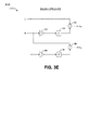
これらの効果を抑制するために、クロストークキャンセラ350aは、2つのスピーカ間のクロストークを相殺する、または他の方法で低減することができる。テレビスピーカについて、よりよい深度レンダリングを容易にするのに加えて、クロストークキャンセラ350aは、携帯電話、タブレット、および他の携帯型電子デバイス上の背面を向くスピーカを含む他のスピーカについて、よりよい深度レンダリングを容易にすることができる。クロストークキャンセラの一例350が図3Eに、より詳細に示されている。このクロストークキャンセラ350bは、図3Dのクロストークキャンセラ350aの多くの可能な実装形態の1つを表す。
To suppress these effects, the
クロストークキャンセラ350bは、2つの信号を、すなわち、上述のように深度効果で処理された左および右の信号を受信する。各信号がインバータ352、362により反転させられる。各インバータ352、362の出力が、遅延ブロック354、364により遅延させられる。遅延ブロックの出力が、加算器356、366で入力信号と加算される。したがって、各信号が、出力信号を作り出すために、反転させられ、遅延させられ、反対側の入力信号と加算される。遅延が正しく選ばれた場合、反転させられ、遅延させられた信号は、バックウェーブミキシングによるクロストーク(または他のクロストーク)を相殺する、または少なくとも部分的に低減するはずである。
The
遅延ブロック354、364の遅延は、両耳間の音波移動時間の差を表すことができ、リスナから複数のスピーカまでの距離に依存することができる。デバイスの大部分のユーザに対して、期待される遅延と整合するように、デバイスの製造業者が深度処理システム110、310を組み込むことにより遅延を設定することができる。ユーザがデバイス(ラップトップなど)の近くに座るデバイスが、ユーザがデバイス(たとえばテレビ)から離れて座るデバイスより短い遅延を有する可能性が高い。したがって、使用されるデバイスのタイプに基づき、複数の遅延設定をカスタマイズすることができる。これらの遅延設定は、ユーザ(たとえば、デバイスの製造業者、デバイス上のソフトウェアの工事担当者、またはエンドユーザなど)が選択するために、ユーザインタフェースの形で公開することができる。あるいは、遅延を事前設定することができる。他の実施形態では、遅延は、複数のスピーカを基準にしたリスナの位置に関して得られる位置情報に基づき、動的に変更することができる。この位置情報は、カメラまたは光学センサ、たとえばマイクロソフト(Microsoft(商標) Corporation)から入手できるXbox(商標) Kinect(商標)から得ることができる。
The delay of the delay blocks 354, 364 can represent the difference in sound wave travel time between both ears and can depend on the distance from the listener to multiple speakers. For most users of the device, the device manufacturer can set the delay by incorporating the
同じく、複数の頭部伝達関数(HRTF)フィルタなどを含んでもよい他の複数の形の複数のクロストークキャンセラが使用されてもよい。HRTFから派生した複数のフィルタをすでに含んでいる場合があるサラウンドプロセッサ340がシステムから除去された場合、クロストークキャンセラ350に複数のHRTFフィルタを追加することで、より大きなスイートスポット、および広大さの感覚が提供される場合がある。いくつかの実施形態では、サラウンドプロセッサ340もクロストークキャンセラ350も、複数のHRTFフィルタを含むことができる。 Similarly, a plurality of other forms of crosstalk cancellers that may include a plurality of head related transfer function (HRTF) filters or the like may be used. If surround processor 340, which may already contain multiple filters derived from HRTF, is removed from the system, adding multiple HRTF filters to crosstalk canceller 350 will result in a larger sweet spot, and a larger A sense may be provided. In some embodiments, both the surround processor 340 and the crosstalk canceller 350 can include multiple HRTF filters.
図4は、本明細書で説明する深度処理システム110、310のいずれによっても、または本明細書で説明しない他のシステムにより、実現することができる深度レンダリング処理400の一実施形態を示す。深度レンダリング処理400は、深度をレンダリングして、没入型オーディオリスニング体験を生み出すための一例の手法を示す。
FIG. 4 illustrates one embodiment of a
ブロック402で、1つまたは複数のオーディオ信号を含む入力オーディオを受信する。2つ以上のオーディオ信号は、左および右のステレオ信号、上述のような5.1サラウンド信号、他の複数のサラウンド構成(たとえば、6.1、7.1など)、複数のオーディオオブジェクト、または深度処理システムが深度レンダリングの前にステレオに変換することができるモノラルオーディオさえ含むことができる。ブロック404で、ある期間にわたり入力信号に関連する深度情報を推定する。深度情報は、上述のようにオーディオ自体の解析から(図5も参照のこと)、ビデオ情報から、オブジェクトメタデータから、またはこれらの任意の組合せから、直接推定してもよい。
At
ブロック406で、推定された深度情報に依存する量により、1つまたは複数のオーディオ信号を動的に脱相関する。ブロック408で、脱相関されたオーディオを出力する。この脱相関は、推定された深度に基づき動的にオーディオの2チャンネル間で位相および/またはゲインの複数の遅延を調節することを伴うことができる。したがって、推定された深度は、生み出された脱相関の量を駆動するステアリング信号の役割を果たすことができる。入力オーディオ内の複数の音源が一方のスピーカからもう一方へ動的に動くとき、脱相関は、対応するやり方で動的に変化することができる。たとえば、ステレオ設定では、サウンドが左スピーカから右スピーカに動く場合、左スピーカ出力が最初に強調され、続いて、音源が右スピーカに動いたとき、右スピーカが強調されてもよい。一実施形態では、脱相関は、効果的に2チャンネル間の差を増大させることになり、より大きなL−RまたはLS−RSの値を作り出す。
At
図5は、深度推定器520のより詳細な一実施形態を示す。深度推定器520は、上述の深度推定器320の特徴のいずれも実現することができる。描かれる実施形態では、深度推定器520は、左および右の入力信号に基づき深度を推定し、出力を深度レンダラ530に提供する。深度推定器520はまた、左および右のサラウンド入力信号から深度を推定するために使用することができる。さらに、深度推定器520の実施形態は、本明細書で説明するビデオ深度推定器またはオブジェクトフィルタ変換モジュールとともに使用することができる。
FIG. 5 shows a more detailed embodiment of
左および右の信号は、和ブロック502および差ブロック504に提供される。一実施形態では、深度推定器520は、左および右のサンプルのブロックを一度に受信する。したがって、深度推定器520の残りの部分が、複数のサンプルのブロックを操作することができる。和ブロック502はL+R出力を作り出すが、差ブロック504はL−R出力を作り出す。これらの出力の各々が、元の入力と一緒に、包絡線検出器510に提供される。
The left and right signals are provided to sum block 502 and
包絡線検出器510は、さまざまな技法のいずれかを使用して、L+R、L−R、L、およびRの信号(またはこれらの信号のサブセット)の包絡線を検出することができる。1つの包絡線検出技法が、信号の2乗平均平方根(RMS)値を得ることである。したがって、包絡線検出器510の包絡線信号出力が、RMS(L−R)、RMS(L)、RMS(R)、およびRMS(L+R)と示される。これらのRMS出力は、平滑器512に提供され、平滑器512は、複数のRMS出力に平滑化フィルタを適用する。包絡線を得て、複数のオーディオ信号を平滑化することにより、複数のオーディオ信号内の(ピークなどの)変動を取り除くことができ、それにより、深度処理でその後の急激なまたは耳障りな変化を避ける、または低減する。一実施形態では、平滑器512は、立ち上がりが速く立ち下がりが緩やかな(fast−attack、slow−decay、FASD)平滑器である。他の実施形態では、平滑器512を省略することができる。 The envelope detector 510 can detect the envelope of the L + R, LR, L, and R signals (or a subset of these signals) using any of a variety of techniques. One envelope detection technique is to obtain the root mean square (RMS) value of the signal. Accordingly, the envelope signal output of the envelope detector 510 is denoted as RMS (LR), RMS (L), RMS (R), and RMS (L + R). These RMS outputs are provided to a smoother 512, which applies a smoothing filter to the plurality of RMS outputs. By obtaining an envelope and smoothing multiple audio signals, you can remove fluctuations (such as peaks) in the multiple audio signals, thereby reducing subsequent sudden or harsh changes in depth processing. Avoid or reduce. In one embodiment, smoother 512 is a fast-attack, slow-decay (FASD) smoother that rises quickly and falls slowly. In other embodiments, the smoother 512 can be omitted.
平滑器512の複数の出力は、図5ではRMS()’と示される。RMS(L+R)’信号が深度計算機524に提供される。上述のように、L−R信号の大きさが、2つの入力信号の深度情報を反映することができる。したがって、RMSおよび平滑化されたL−R信号の大きさが、同じく深度情報を反映することができる。たとえば、RMS(L−R)’信号のより大きな大きさが、RMS(L−R)’信号のより小さな大きさより近い信号を反映することができる。前記他の方法、すなわちL−RまたはRMS(L−R)’の信号の値が、L−Rの複数の信号間の相関の程度を反映する。詳細には、L−RまたはRMS(L−R)’(またはRMS(L−R))信号が、左信号と右信号の間の両耳間相互相関係数(interaural cross−correlation coefficient、IACC)の逆指標とすることができる(たとえば、LおよびRの信号に強い相関がある場合、これらの信号のL−R値は0に近くなるが、これらの信号のIACC値は1に近くなり、弱い相関がある場合、逆も成り立つ)。
The plurality of outputs of the smoother 512 are shown as RMS () 'in FIG. The RMS (L + R) ′ signal is provided to the
RMS(L−R)’信号は、LおよびRの信号間の逆相関を反映させることができるので、LおよびRの出力信号の間にどれだけの脱相関を適用すべきかを判定するために、RMS(L−R)’信号を使用することができる。深度計算機524は、RMS(L−R)’信号をさらに処理して、深度推定値を提供することができ、深度推定値は、LおよびRの信号に脱相関を適用するために使用することができる。一実施形態では、深度計算機524は、RMS(L−R)’信号を正規化する。たとえば、包絡線信号を正規化するために、LおよびRの信号の幾何平均(または他の平均または統計的尺度)でRMS値を除算することができる(たとえば、(RMS(L)’*RMS(R)’)∧(1/2))。正規化は、信号レベルまたはボリュームのゆらぎが、深度のゆらぎとして誤って解釈されないことを保証するのに役立つことができる。したがって、図5に示すように、RMS(L)’およびRMS(R)’の値は、乗算ブロック538で一緒に操作され、深度計算機524に提供され、深度計算機524は正規化処理を完了することができる。
The RMS (LR) 'signal can reflect the inverse correlation between the L and R signals, so to determine how much decorrelation should be applied between the L and R output signals , RMS (LR) ′ signal can be used. The
RMS(L−R)’信号を正規化することに加えて、深度計算機524はまた、追加処理を適用することができる。たとえば、深度計算機524は、非線形処理をRMS(L−R)’信号に適用してもよい。この非線形処理は、RMS(L−R)’信号の大きさを強めて、それにより、RMS(L−R)’信号内の既存の脱相関を非線形に強調することができる。したがって、L−R信号内の速い変化を、L−R信号に対する遅い変化よりさらに大きく強調することができる。非線形処理は、一実施形態では、冪関数もしくは指数関数的である、または他の実施形態では、線形増加より大きい。たとえば、深度計算機524は、x∧aなどの指数関数を使用することができ、ここで、x=RMS(L−R)’であり、a>1である。非線形処理のために、異なる複数の形の複数の指数関数を含む他の複数の関数を選んでもよい。
In addition to normalizing the RMS (LR) 'signal, the
深度計算機524は、正規化され、非線形処理された信号を深度推定値として係数計算ブロック534およびサラウンド・スケール・ブロック536に提供する。係数計算ブロック534は、深度推定値の大きさに基づき、深度レンダリングフィルタの複数の係数を計算する。図6Aおよび図6Bに関連して、深度レンダリングフィルタについて以下でより詳細に説明する。しかしながら、一般に、計算ブロック534により生成される複数の係数は、左および右のオーディオ信号に適用される位相遅延および/またはゲイン調節の量に影響を及ぼす可能性があることに留意されたい。したがって、たとえば、計算ブロック534は、より大きな値の複数の深度推定値に対してより大きな位相遅延を作り出す複数の係数を生成することができ、逆も成り立つ。一実施形態では、計算ブロック534により生成される位相遅延と、深度推定値との間の関係が、冪関数または同種のものなどの非線形である。この冪関数は、深度推定器520が実現されるタイプのデバイスにより判定されてもよい、リスナから複数のスピーカまでの近さに基づき任意選択で調整可能なパラメータである冪を有する。テレビは、たとえば、予想されるリスナの距離が携帯電話より大きい場合があり、したがって、計算ブロック534は、テレビまたは他のタイプのデバイスに対して冪関数を異なるように調整することができる。計算ブロック534により適用される冪関数は、深度推定の効果を拡大することができ、誇張された位相/および振幅の遅延をもたらす、深度レンダリングフィルタの複数の係数をもたらす。他の実施形態では、位相遅延と深度推定値の間の関係は、非線形ではなく線形(または両方の組合せ)である。
The
サラウンド・スケール・モジュール536は、任意選択のサラウンドプロセッサ340により適用されるサラウンド処理の量を調節する信号を出力することができる。したがって、深度推定値により計算されるようなL−Rコンテンツの脱相関または広大さの量が、適用されるサラウンド処理の量を変調することができる。サラウンド・スケール・モジュール536は、より大きな深度推定値に対してより大きな値を、およびより小さな深度推定値に対してより小さな値を有するスケール値を出力することができる。一実施形態では、サラウンド・スケール・モジュール536は、冪関数または同種のものなどの非線形処理を深度推定値に適用して、スケール値を作り出す。たとえば、スケール値は、深度推定値の冪の何らかの関数とすることができる。他の実施形態では、スケール値および深度推定値は、非線形ではなく線形(または両方の組合せ)の関係を有する。スケール値により適用される処理について図13〜図17に関連して以下でより詳細に説明する。
The
また、別個に、RMS(L)’およびRMS(R)’の信号が、遅延および振幅計算ブロック540に提供される。計算ブロック540は、たとえば可変遅延線ポインタを更新することより、深度レンダリングフィルタ(図6Aおよび図6B)に適用される遅延の量を計算することができる。一実施形態では、計算ブロック540は、LおよびRの信号(またはこれらのRMS()’均等物)のどちらが優勢であるか、またはレベルがより高いかを判定する。計算ブロック540は、RMS(L)’/RMS(R)’として2つの信号の比を得ることにより、この優勢を判定することができ、1より大きな値が左の優勢を示し、1未満の値が右の優勢を示す(分子および分母が逆である場合、逆が成り立つ)。あるいは、計算ブロック540は、2つの信号の単純な差を実施して、より大きな大きさを有する信号を判定する。
Separately, RMS (L) 'and RMS (R)' signals are provided to the delay and
左信号が優勢である場合、計算ブロック540は、深度レンダリングフィルタの左部分(図6A)を調節して、左信号に適用される位相遅延を低減することができる。右信号が優勢である場合、計算ブロック540は、右信号に適用されるフィルタ(図6B)に対して同じことを実施することができる。信号の優勢は変化するので、計算ブロック540は、深度レンダリングフィルタに対する遅延線の値を変更することができ、左および右のチャンネル間で時間とともに位相遅延にプッシュプル変化を引き起こす。位相遅延のこのプッシュプル変化は、(たとえば優勢が変化する時間の間)選択的にチャンネル間で脱相関を増大させる、およびチャンネル間で相関を増大させる役割を少なくとも一部は果たすことができる。計算ブロック540は、左および右の信号優勢の変化に応答して、左と右の間で遅延優勢をフェードして、耳障りな変化または信号アーチファクトを出力するのを避けることができる。
If the left signal is dominant, the
さらに、計算ブロック540は、左および右の信号(またはこれらの信号の処理された値、たとえばRMS値)の比に基づき、左および右のチャンネルに適用される全体ゲインを計算することができる。計算ブロック540は、これらのゲインを、位相遅延のプッシュプル変化に類似するプッシュプルのやり方で変更することができる。たとえば、左信号が優勢である場合、計算ブロック540は、左信号を増幅し、右信号を減衰させることができる。右信号が優勢になったとき、計算ブロック540は、右信号を増幅し、左信号を減衰させることができるなど。計算ブロック540はまた、チャンネル間でゲインをクロスフェードして、耳障りなゲイン移行または信号アーチファクトを避けることができる。
Further, the
したがって、ある種の実施形態では、遅延および振幅計算機は、深度レンダラ530に位相遅延および/またはゲインを脱相関させる複数のパラメータを計算する。事実上、遅延および振幅計算機540は、深度レンダラ530に、左および右の信号間の既存の位相および/またはゲインの脱相関を増幅する拡大鏡または増幅器の役割を果たさせることができる。任意の所与の実施形態で、単に位相遅延脱相関またはゲイン脱相関が実施されてもよい。
Thus, in certain embodiments, the delay and amplitude calculator calculates a plurality of parameters that cause the
深度計算機524、係数計算機ブロック534、および計算ブロック540は、一緒に作動して、深度レンダラ530の深度レンダリング効果を制御することができる。したがって、一実施形態では、脱相関によりもたらされる深度レンダリングの量は、多分、複数の要因に、たとえば優勢なチャンネルおよび(任意選択で、処理された)差情報(たとえば、L−Rなど)に依存することができる。図6Aおよび図6Bに関連して以下でより詳細に説明するように、異なる情報に基づく、ブロック534からの係数計算結果は、深度レンダラ530により提供される移動遅延効果をオンまたはオフすることができる。したがって、一実施形態では、差情報は、チャンネル優勢情報が位相遅延の量を制御する間に位相遅延が実施される、および/またはゲイン脱相関が実施されるかどうかを効果的に制御する。他の実施形態では、差情報はまた、実施される位相脱相関および/またはゲイン脱相関の量に影響を及ぼす。
図示する実施形態以外の実施形態では、単に位相および/またはゲインの脱相関の量を制御するために、深度計算機524の出力を使用することができるが、係数計算を制御するために、計算ブロック540の出力を使用することができる(たとえば、計算ブロック534に提供することができる)。他の実施形態では、深度計算機524の出力を計算ブロック540に提供し、差情報と優勢情報の両方に基づき、計算ブロック540の位相および振幅の脱相関パラメータ出力を制御する。同様に、係数計算ブロック534は、計算ブロック540から追加の複数の入力を得て、差情報および優勢情報の両方に基づき、複数の係数を計算することができる。
In embodiments other than the illustrated embodiment, the output of the
RMS(L+R)’信号はまた、描かれた実施形態では、非線形処理(NLP)ブロック522に提供される。NLPブロック522は、たとえば、RMS(L+R)’信号に指数関数を適用することにより、深度計算機524により適用されたのと類似するNLP処理をRMS(L+R)’に実施することができる。多くのオーディオ信号では、L+R情報は対話を含み、しばしばセンターチャンネルの代替物として使用される。非線形処理によりL+Rブロックの値を拡張することは、L+RまたはCの信号にどれだけのダイナミックレンジ圧縮を適用すべきかを判定する際に有用となることができる。より大きな値の圧縮が、より大きな音の、したがってより明瞭な対話をもたらすことができる。しかしながら、L+R信号の値が非常に小さい場合、対話が存在しない場合があり、したがって、適用される圧縮の量を低減することができる。したがって、L+RまたはCの信号に適用される圧縮の量を調節するために、圧縮スケールブロック550によりNLPブロック522の出力を処理することができる。
The RMS (L + R) 'signal is also provided to a non-linear processing (NLP) block 522 in the depicted embodiment. NLP block 522 may perform NLP processing similar to that applied by
異なる実施形態では、深度推定器520の多くの態様を修正または省略することができることに留意されたい。たとえば、包絡線検出器510または平滑器512は省略されてもよい。したがって、L−R信号に直接基づき深度推定を行うことができ、信号優勢はLおよびRの信号に直接基づくことができる。この場合、入力信号を平滑化する代わりに、深度推定値および優勢の計算結果(ならびL+Rに基づく圧縮スケール計算結果)を平滑化することができる。さらに、他の実施形態では、計算ブロック540で遅延線ポインタ計算結果を調節するために、L−R信号(またはこの信号の平滑化された/包絡線バージョン)または深度計算機524からの深度推定値を使用することができる。同様に、ブロック534で複数の係数計算結果を操作するために、(たとえば、比または差により計算された)LとRの信号間の優勢を使用することができる。同様に、圧縮スケールブロック550またはサラウンド・スケール・ブロック536が省略されてもよい。以下でより詳細に説明するビデオ深度推定などの、多くの他の追加態様が、同じく深度推定器520に含まれてもよい。
It should be noted that in different embodiments, many aspects of the
図6Aおよび図6Bは、深度レンダラ630A、630Bの実施形態を示し、上述の深度レンダラ330、530のより詳細な実施形態を表す。図6Aの深度レンダラ630Aは、左チャンネルに対して深度レンダリングフィルタを適用するが、一方、図6Bの深度レンダラ630Bは、右チャンネルに対して深度レンダリングフィルタを適用する。したがって、各図で示す構成要素が同一である(そうはいっても、いくつかの実施形態では、2つのフィルタ間に違いが提供されてもよい)。したがって、便宜上、単一の深度レンダラ630として深度レンダラ630A、630Bについて一般的な形で説明する。
6A and 6B show an embodiment of depth renderers 630A, 630B and represent a more detailed embodiment of the
上述の(および図6Aのおよび図6Bで再現された)深度推定器520は、深度レンダラ630にいくつかの入力を提供することができる。これらの入力は、可変遅延線610、622に提供される1つまたは複数の遅延線ポインタ、乗算器602に適用される複数のフィードフォワード係数、乗算器616に適用される複数のフィードバック係数、および乗算器624に提供される(たとえば、図5のブロック540から得られる)全体ゲイン値を含む。
The
深度レンダラ630は、ある種の実施形態では、入力信号の位相を調節することができる全域通過フィルタである。描かれた実施形態では、深度レンダラ630は、フィードフォワード構成要素632およびフィードバック構成要素634を有する無限インパルス応答(IIR)フィルタである。一実施形態では、実質的に類似の位相遅延効果を得るために、フィードバック構成要素634を省略することができる。しかしながら、フィードバック構成要素634がなければ、潜在的に、いくつかのオーディオ周波数がゼロにされる、または他の方法で減衰させられる櫛形フィルタ効果が発生する可能性がある。したがって、フィードバック構成要素634は、有利には、この櫛形フィルタ効果を低減する、または取り除くことができる。フィードフォワード構成要素632はフィルタ630Aのゼロ点を表すが、フィードバック構成要素634はフィルタ630Aの極を表す(図7および図8を参照のこと)。
Depth renderer 630 is an all-pass filter that, in certain embodiments, can adjust the phase of the input signal. In the depicted embodiment, depth renderer 630 is an infinite impulse response (IIR) filter having a
フィードフォワード構成要素632は、可変遅延線610、乗算器602、および結合器612を含む。可変遅延線610は、入力として入力信号(たとえば図6Aでは左信号)を得て、深度推定器520により判定される量に従って信号を遅延させ、遅延した信号を結合器612に提供する。入力信号はまた、乗算器602に提供され、乗算器602は、信号を基準化し、基準化された信号を結合器612に提供する。乗算器602は、図5の係数計算ブロック534により計算されたフィードフォワード係数を表す。
結合器612の出力が、可変遅延線622、乗算器616、および結合器614を含むフィードバック構成要素634に提供される。フィードフォワード構成要素632の出力が、結合器614に提供され、結合器614は、出力を可変遅延線622に提供する。可変遅延線622は、可変遅延線610の遅延に対応する遅延を有し、深度推定器520(図5を参照のこと)による出力に依存する。遅延線622の出力が、乗算器ブロック616に提供される、遅延した信号である。乗算器616は、係数計算ブロック534(図5を参照のこと)により計算されたフィードバック係数を適用する。このブロック616の出力が、結合器614に提供され、結合器614はまた、出力を乗算器624に提供する。この乗算器624は、(以下で説明する)全体ゲインを深度レンダリングフィルタ630に提供する。
The output of
フィードフォワード構成要素632の乗算器602は、入力信号+遅延した信号のウェット/ドライミックスを制御することができる。乗算器602に適用されるより多くのゲインが、遅延した信号(ウェット、またはより反響する信号)に対して入力信号(ドライまたはより反響しない信号)の量を増大させることができ、逆も成り立つ。より少ないゲインを入力信号に適用することにより、入力信号の位相遅延したバージョンを優勢にすることができ、深度効果を強調し、逆も成り立つ。乗算器602により適用された余分なゲインを補償するために、このゲインの反転されたバージョン(図示せず)が可変遅延ブロック610に含まれてもよい。櫛形フィルタを適切にゼロに相殺するために、乗算器616のゲインをゲイン602に一致するように選ぶことができる。したがって、ある種の実施形態では、乗算器602のゲインは、時間で変化するウェット−ドライミックスを変調することができる。
The
動作については、左および右の入力信号(またはLSおよびRSの信号)を選択的に相関および脱相関するために、深度推定器520により2つの深度レンダリングフィルタ630A、630Bを制御することができる。両耳間時間遅延、およびしたがって左(より大きな深度が左から検出されたと仮定する)から得られる深度の感覚を生み出すために、左の遅延線610(図6A)を一方の方向に調節することができ、一方、右の遅延線610(図6B)を反対方向に調節する。2チャンネル間で反対のやり方で遅延を調節することにより、チャンネル間に位相差を生み出し、それにより、チャンネルを脱相関することができる。同様に、左ゲイン(図6Aの乗算器ブロック624)を一方の方向に調節し、一方、右ゲイン(図6Bの乗算器ブロック624)を他方の方向に調節することにより、両耳間強度差を生み出すことができる。したがって、オーディオ信号の深度が左と右のチャンネル間でシフトするとき、深度推定器520は、チャンネル間の遅延およびゲインをプッシュプルのやり方で調節することができる。あるいは、左および右の遅延および/またはゲインの一方だけを任意の所与の時間に調節することができる。
In operation, two depth rendering filters 630A, 630B can be controlled by
一実施形態では、深度推定器520は、(遅延線610の)遅延またはゲイン624をランダムに変えて、2チャンネル間のITDおよびIIDの差をランダムに変える。このランダムな変動は、小さく、または大きくすることができるが、いくつかの実施形態では、微妙なランダムな変動が、より自然なサウンドの、没入できる環境をもたらすことができる。さらに、音源が入力オーディオ信号内でリスナから遠く離れて、またはより近く移動するとき、深度レンダリングモジュールは、深度レンダリングフィルタ630の出力に線形のフェーディングおよび/または平滑化(図示せず)を適用して、2チャンネルの深度調節間の滑らかな移行を提供することができる。
In one embodiment, the
ある種の実施形態では、乗算器602に適用されるステアリング信号が比較的大きい(たとえば、>1)とき、深度レンダリングフィルタ630は、すべてのゼロ点が単位円の外側にある最大位相フィルタになり、位相遅延が導入される。この最大位相効果の一例が図7Aに示され、図7Aは、ゼロ点を単位円の外側に有する極−ゼロ点プロット710を示す。対応する位相プロット730を図7Bに示し、図7Bは、比較的大きな値の乗算器602係数に対応する、約32サンプルの一例の遅延を示す。乗算器602係数の値を調節することにより他の遅延値を設定することができる。
In certain embodiments, when the steering signal applied to
乗算器602に適用されるステアリング信号が比較的小さい(たとえば、<1)とき、深度レンダリングフィルタ630は、このゼロ点が単位円の内側にある最小位相フィルタになる。その結果、位相遅延はゼロに(またはゼロに近く)なる。この最小位相効果の一例が図8Aに示され、図8Aは、すべてのゼロ点を単位円の内側に有する極−ゼロ点プロット810を示す。対応する位相プロット830を図8Bに示し、図8Bは0サンプルの遅延を示す。
When the steering signal applied to
図9は、一例の周波数領域の深度推定処理900を示す。周波数領域処理900は、上述のシステム110、310のいずれかにより実現することができ、図6A〜図8Bに関連して上記で説明した時間領域フィルタの代わりに使用されてもよい。したがって、時間領域または周波数領域(または両方)で深度レンダリングを実施することができる。
FIG. 9 shows an example frequency domain
一般に、深度を強調するために、さまざまな周波数領域の技法を使用して、左および右の信号をレンダリングすることができる。たとえば、各入力信号に対して、高速フーリエ変換(FFT)を計算することができる。次いで、各FFT信号の位相を調節して、信号間の位相差を生み出すことができる。同様に、2つのFFT信号に、強度差を適用することができる。逆FFTを各信号に適用して、時間領域の、レンダリングされた出力信号を作り出すことができる。 In general, left and right signals can be rendered using various frequency domain techniques to enhance depth. For example, a fast Fourier transform (FFT) can be calculated for each input signal. The phase of each FFT signal can then be adjusted to produce a phase difference between the signals. Similarly, an intensity difference can be applied to the two FFT signals. An inverse FFT can be applied to each signal to produce a time-domain, rendered output signal.
具体的に図9を参照すると、ブロック902で、複数のサンプルのステレオブロックを受信する。複数のサンプルのステレオブロックは、左および右のオーディオ信号を含むことができる。ブロック904で、複数のサンプルのブロックに窓関数904を適用する。ハミング窓またはハニング窓などの任意の適切な窓関数を選択することができる。ブロック906で、各チャンネルに対して高速フーリエ変換(FFT)を計算して、周波数領域の信号を作り出し、ブロック908で、各チャンネルの周波数領域信号から大きさおよび位相の情報を抽出する。
Referring specifically to FIG. 9, at
周波数領域信号の位相角を変更することにより、ITD効果のための位相遅延を周波数領域で成し遂げることができる。同様に、2チャンネル間でパンすることにより、2チャンネル間のIID効果のための大きさ変更を成し遂げることができる。したがって、ブロック910および912で、周波数に依存する複数の角度およびパニングを計算する。これらの角度およびパニングゲインを、深度推定器320または520により出力される複数の制御信号に少なくとも一部は基づき計算することができる。たとえば、左チャンネルが優勢であることを示す、深度推定器520からの優勢制御信号が、周波数に依存するパニングに、左チャンネルにパンする一連のサンプルにわたりゲインを計算させることができる。同様に、RMS(L−R)’信号または同種のものを使用して、変化する複数の位相角に反映される複数の位相変化を計算することができる。
By changing the phase angle of the frequency domain signal, a phase delay for the ITD effect can be achieved in the frequency domain. Similarly, panning between two channels can achieve a size change for the IID effect between the two channels. Accordingly, at
ブロック914で、回転変換を使用して、たとえば極の複数の複素位相シフトを使用して、複数の位相角および複数のパニング変化を複数の周波数領域信号に適用する。ブロック916で、各信号における大きさおよび位相の情報を更新する。次いで、ブロック918で、大きさおよび位相の情報を極複素形式からデカルト複素形式に逆変換して、逆FFT処理を可能にする。FFTアルゴリズムの選択に応じて、いくつかの実施形態では、この逆変換ステップを省略することができる。
At
ブロック920で、各周波数領域信号に対して逆FFTを計算して、複数の時間領域信号を作り出す。次いで、ブロック922で、重畳加算合成(overlap−add synthesis)を使用して、ステレオ・サンプル・ブロックを直前のステレオ・サンプル・ブロックと結合し、次いで、ブロック924で出力する。
At
III.ビデオ深度推定実施形態
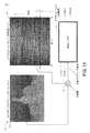
図10Aおよび図10Bは、深度を推定するために使用することができるビデオフレーム1000の例を示す。図10Aでは、ビデオフレーム1000Aが、ビデオからのカラーシーンを描く。深度マッピングをより好都合に示すために、簡略化されたシーンが選択されたが、図示する特定のビデオフレーム1000Aでは、複数のオブジェクトのいずれからもオーディオを発する可能性がない。カラー・ビデオ・フレーム1000Aに基づき、図10Bのグレースケールのフレーム1000Bで示すように、現在利用可能な技法を使用して、グレースケール深度マップが生み出されてもよい。グレースケール画像内の画素の輝度が、画像内の画素の深度を反映し、より暗い画素がより大きな深度を反映し、より明るい画素がより小さな深度を反映する(これらの表記法を逆にすることができる)。
III. Video Depth Estimation Embodiment FIGS. 10A and 10B show an example of a video frame 1000 that can be used to estimate depth. In FIG. 10A,
任意の所与のビデオについて、深度推定器(たとえば320)が、ビデオ内の1つまたは複数のフレームに対するグレースケール深度マップを得ることができ、フレーム内の深度の推定値を深度レンダラ(たとえば330)に提供することができる。深度レンダラは、深度情報が得られた特定のフレームが示されるビデオ内の時間に対応するオーディオ信号で深度効果をレンダリングすることができる(図11参照のこと)。 For any given video, a depth estimator (eg, 320) can obtain a grayscale depth map for one or more frames in the video, and an estimate of the depth in the frame is used as a depth renderer (eg, 330). ) Can be provided. The depth renderer can render the depth effect with an audio signal corresponding to the time in the video where the particular frame from which the depth information was obtained is shown (see FIG. 11).
図11は、ビデオデータから深度を推定するために使用することができる深度推定およびレンダリングアルゴリズム1100の一実施形態を示す。アルゴリズム1100は、ビデオフレームのグレースケール深度マップ1102、およびスペクトル・パン・オーディオ深度マップ1104を受信する。ビデオフレームが再生される時間に対応する、オーディオ深度マップ1104内の時間の瞬間を選択することができる。相関器1110が、グレースケール深度マップ1102から得られる深度情報を、スペクトル・パン・オーディオ・マップ(またはL−R、L、および/またはRの信号)から得られた深度情報と結合することができる。この相関器1110の出力を、深度レンダラ1130(または330または630)によりレンダリングされる深度を制御する1つまたは複数の深度ステアリング信号とすることができる。
FIG. 11 illustrates one embodiment of a depth estimation and rendering algorithm 1100 that can be used to estimate depth from video data. The algorithm 1100 receives a
ある種の実施形態では、深度推定器(図示せず)は、グレースケール深度マップを領域に、たとえば4分の1、2分の1または同種のものに分割することができる。次いで、深度推定器は、領域内の画素深度を解析して、どの領域が優勢であるかを判定することができる。たとえば左の領域が優勢である場合、深度推定器は、深度レンダラ1130に左信号を強調させるステアリング信号を生成することができる。深度推定器は、このステアリング信号を、上述のように(図5を参照のこと)オーディオステアリング信号(複数)と組み合わせて、またはオーディオ信号を使用することなく独立して、生成することができる。 In certain embodiments, a depth estimator (not shown) may divide the grayscale depth map into regions, for example, a quarter, a quarter, or the like. The depth estimator can then analyze the pixel depth within the region to determine which region is dominant. For example, if the left region is dominant, the depth estimator may generate a steering signal that causes the depth renderer 1130 to enhance the left signal. The depth estimator can generate this steering signal as described above (see FIG. 5) in combination with the audio steering signal (s) or independently without using the audio signal.
図12は、ビデオデータに基づく、深度の一例の解析プロット1200を示す。プロット1200では、ピークが、図11のビデオとオーディオのマップ間の相関を反映している。これらのピークの場所が時間とともに変化するにつれ、深度推定器は、それに従ってオーディオ信号を脱相関して、ビデオおよびオーディオの信号内の深度を強調することができる。
FIG. 12 shows an
IV.サラウンド処理実施形態
図3Aに関連して上述したように、深度レンダリングされた左および右の信号が、任意選択のサラウンド処理モジュール340aに提供される。上述のように、サラウンドプロセッサ340aは、上記で組み込まれた米国特許第7,492,907号明細書で説明される1つまたは複数の遠近感曲線または同種のものを使用して、サウンドステージを広げ、それにより、スイートスポットを広くして、深度の感覚を増大させることができる。
IV. Surround Processing Embodiment As described above in connection with FIG. 3A, depth-rendered left and right signals are provided to an optional surround processing module 340a. As described above, the surround processor 340a uses one or more perspective curves or the like described in US Pat. No. 7,492,907 incorporated above to sound stage. Widen, thereby widening the sweet spot and increasing the sense of depth.
一実施形態では、制御信号の1つ、すなわちL−R信号(またはこの信号の正規化された包絡線)を使用して、サラウンド処理モジュール(図5を参照のこと)により適用されるサラウンド処理を変調することができる。L−R信号のより大きな大きさが、より大きな深度を反映することができるので、L−Rが比較的より大きいときに、より大きなサラウンド処理を適用することができ、L−Rが比較的より小さいときに、より小さなサラウンド処理を適用することができる。遠近感曲線(複数)に適用されるゲイン値を調節することにより、サラウンド処理を調節することができる。適用されるサラウンド処理の量を調節することにより、オーディオ信号内にわずかな深度が存在するときに、サラウンド処理をあまりにも多く適用しすぎる、潜在的な逆効果を低減することができる。 In one embodiment, the surround processing applied by the surround processing module (see FIG. 5) using one of the control signals, ie, the LR signal (or the normalized envelope of this signal). Can be modulated. Since the larger magnitude of the LR signal can reflect the greater depth, larger surround processing can be applied when the LR is relatively larger, and the LR is relatively higher. When smaller, smaller surround processing can be applied. Surround processing can be adjusted by adjusting the gain value applied to the perspective curve (s). Adjusting the amount of surround processing applied can reduce the potential adverse effect of applying too much surround processing when there is a small depth in the audio signal.
図13〜図16は、サラウンドプロセッサの実施形態を示す。図17および図18は、仮想サラウンド効果を生み出すために複数のサラウンドプロセッサにより使用することができる、複数の遠近感曲線の実施形態を示す。 13-16 illustrate an embodiment of a surround processor. FIGS. 17 and 18 illustrate embodiments of multiple perspective curves that can be used by multiple surround processors to create a virtual surround effect.
図13に戻ると、サラウンドプロセッサ1340の一実施形態が示されている。サラウンドプロセッサ1340は、上述のサラウンドプロセッサ340のより詳細な一実施形態である。サラウンドプロセッサ1340は、パッシブ・マトリックス・デコーダ、サークル・サラウンド・デコーダ(「5−2−5マトリックスシステム(5−2−5 Matrix System)」と題する米国特許第5,771,295明細書を参照のこと、この特許の開示は全体が参照により本明細書に組み入れられる)、または同種のものであってもよいデコーダ1380を含む。デコーダ1380は、(たとえば深度レンダラ330aから受信された)左および右の入力信号を、遠近感曲線フィルタ(複数)1390でサラウンド処理することができる複数の信号に復号することができる。一実施形態では、デコーダ1380の出力は、左、右、センター、およびサラウンドの信号を含む。サラウンド信号は、左および右のサラウンドの両方を、または単に単一のサラウンド信号を含んでもよい。一実施形態では、デコーダ1380は、LおよびRの信号を加算することにより(L+R)センター信号を合成し、LからRを減算することにより(L−R)リアサラウンド信号を合成する。
Returning to FIG. 13, one embodiment of a
1つまたは複数の遠近感曲線フィルタ(複数)1390は、上述のように、深度レンダリングの目的でスイートスポットを広くすることができるデコーダ1380により出力される複数の信号に対して広大さ拡張を提供することができる。図示するように、L−R差情報に基づき、これらのフィルタ(複数)1390により提供される広大さまたは遠近感の効果を変調または調節することができる。このL−R差情報は、図5に関連して上記で説明した包絡線、平滑化、および/または正規化の効果に従って処理されたL−R差情報であってもよい。
One or more perspective curve filter (s) 1390 provides a breadth extension for the signals output by the
いくつかの実施形態では、サラウンドプロセッサ1340により提供されるサラウンド効果を、深度レンダリングとは無関係に使用することができる。左および右の信号の差情報によりこのサラウンド効果を変調することにより、深度レンダリングとは無関係にサウンド効果の質を拡張することができる。
In some embodiments, the surround effect provided by the
本明細書で説明するシステムおよび方法とともに実現することができる複数の遠近感曲線および複数のサラウンドプロセッサに関する情報が、「録音および再生で使用するための複数チャンネルのオーディオ拡張、ならびにこれを提供する方法(Multi-Channel Audio Enhancement System For Use In Recording And Playback And Methods For Providing Same)」と題する米国特許第7,492,907号明細書、「複数チャンネルオーディオ拡張システム(Multi-Channel Audio Enhancement System)」と題する米国特許第8,050,434号明細書、および「サラウンドサウンド環境で使用するためのオーディオ拡張システム(Audio Enhancement System for Use in a Surround Sound System Environment)」と題する米国特許第5,970,152号明細書にさらに説明されており、これらの特許の各々の開示は、全体が参照により本明細書に組み入れられる。 Information on multiple perspective curves and multiple surround processors that can be implemented with the systems and methods described herein is described in “Multi-channel audio extensions for use in recording and playback, and methods of providing same” US Pat. No. 7,492,907 entitled “Multi-Channel Audio Enhancement System For Use In Recording And Playback And Methods For Providing Same”, “Multi-Channel Audio Enhancement System” U.S. Pat. No. 8,050,434, and U.S. Pat. No. 5,970,152 entitled “Audio Enhancement System for Use in a Surround Sound System Environment”. Are further described in the specification of each of these patents. It is entirely incorporated herein by reference.
図14は、サラウンドプロセッサ1400のより詳細な一実施形態を示す。サラウンドプロセッサ1400を使用して、上述のサラウンドプロセッサ、たとえばサラウンドプロセッサ1340の特徴のいずれも実現することができる。図示しやすくするために、デコーダを示していない。代わりに、オーディオ入力ML(左フロント)、MR(右フロント)、センター(CIN)、任意選択のサブウーファ(B)、左サラウンド(SL)、および右サラウンド(SR)がサラウンドプロセッサ1400に提供され、サラウンドプロセッサ1400は、遠近感曲線フィルタ1470、1406、および1420を複数のオーディオ入力のさまざまなミキシングに適用する。
FIG. 14 illustrates a more detailed embodiment of the
信号MLおよびMRは、音量調節信号M音量により制御される、対応するゲイン調整乗算器1452および1454に供給される。センター信号Cのゲインは、信号M音量により制御される第1の乗算器1456、およびセンター調節信号C音量により制御される第2の乗算器1458により調整されてもよい。同様に、サラウンド信号SLおよびSRは、音量調節信号S音量により制御されるそれぞれの乗算器1460および1462にまず供給される。
Signals ML and MR are provided to corresponding
主要なフロント左信号MLおよびフロント右信号MRは、それぞれ加算接続点1464および1466に供給される。加算接続点1464は、MRを受信する反転入力、およびMLを受信する非反転入力を有し、これらの入力は結合して、出力経路1468に沿ってML−MRを作り出す。信号ML−MRは、伝達関数P1により特徴づけられる遠近感曲線フィルタ1470に供給される。処理された差信号(ML−MR)pが、遠近感曲線フィルタ1470の出力で、ゲイン調節乗算器1472に引き渡される。ゲイン調節乗算器1472は、図5に関連して上記で説明したサラウンドスケール536設定を適用することができる。その結果、遠近感曲線フィルタ1470の出力を、L−R信号内の差情報に基づき変調することができる。
The main front left signal ML and front right signal MR are supplied to summing
乗算器1472の出力が、直接左ミキサ1480に、およびインバータ1482に供給される。反転された差信号(MR−ML)pが、インバータ1482から右ミキサ1484に送信される。和信号ML+MRが接続点1466を出て、ゲイン調節乗算器1486に供給される。ゲイン調節乗算器1486はまた、図5に関連して上記で説明したサラウンドスケール536設定または何らかの他のゲイン設定を適用してもよい。
The output of
乗算器1486の出力が加算接続点に供給され、加算接続点は、センターチャンネル信号Cを信号ML+MRと加算する。結合された信号ML+MR+Cが接続点1490を出て、左ミキサ1480と右ミキサ1484の両方に向けられる。最後に、元の信号MLおよびMRが、ミキサ1480および1484に送信される前に、まず固定されたゲイン調節構成要素、たとえばそれぞれ増幅器1490および1492を通して供給される。
The output of the multiplier 1486 is supplied to the addition connection point, which adds the center channel signal C with the signal ML + MR. The combined signal ML + MR + C exits
サラウンド左信号SLおよびサラウンド右信号SRが、それぞれ乗算器1460および1462を出て、それぞれ加算接続点1400および1402に供給される。加算接続点1401は、SRを受信する反転入力、およびSLを受信する非反転入力を有し、これらの入力は、結合して出力経路1404に沿ってSL−SRを作り出す。加算接続点1464、1466、1400、および1402のすべては、和信号が生成されるか、差信号が生成されるかどうかに応じて、反転増幅器または非反転増幅器として構成されてもよい。反転増幅器も非反転増幅器も、当業者には一般的な原理に従って、通常の演算増幅器から構築されてもよい。信号SL−SRは、伝達関数P2により特徴づけられる遠近感曲線フィルタ1406に供給される。
Surround left signal SL and surround right signal SR leave
処理された差信号(SL−SR)pが、遠近感曲線フィルタ1406の出力で、ゲイン調節乗算器1408に引き渡される。ゲイン調節乗算器1408は、図5に関連して上記で説明したサラウンドスケール536設定を適用することができる。このサラウンドスケール536設定は、乗算器1472により適用されるものと同一でも、異なっていてもよい。他の実施形態では、乗算器1408は省略される、またはサラウンドスケール536設定以外の設定に依存する。
The processed difference signal (SL−SR) p is delivered to the
乗算器1408の出力が、直接左ミキサ1480に、およびインバータ1410に供給される。反転された差信号(SR−SL)pが、インバータ1410から右ミキサ1484に送信される。和信号SL+SRが接続点1402を出て、伝達関数P3により特徴づけられる別個の遠近感曲線フィルタ1420に供給される。処理された和信号(SL+SR)pが、遠近感曲線フィルタ1420の出力で、ゲイン調節乗算器1432に引き渡される。ゲイン調節乗算器1432は、図5に関連して上記で説明したサラウンドスケール536設定を適用することができる。このサラウンドスケール536設定は、乗算器1472、1408により適用されたものと同一でも、異なっていてもよい。他の実施形態では、乗算器1432は省略される、またはサラウンドスケール536設定以外の設定に依存する。
The output of
和および差の信号が参照されているが、実際に和および差の信号を使用するのは代表的でしかないことに留意されたい。1対の信号の、周囲の構成要素およびモノラルの構成要素が、どのように分離されるかにかかわらず、同一処理を達成することができる。乗算器1432の出力が、左ミキサ1480および右ミキサ1484に直接供給される。また、元の信号SLおよびSRは、ミキサ1480および1484に送信される前にまず、それぞれ、固定されたゲインの増幅器1430および1434を通して供給される。最後に、低周波効果チャンネルBが、出力低周波効果信号BOUTを生み出すために、増幅器1436を通して供給される。任意選択で、低周波チャンネルBは、サブウーファが利用可能ではない場合、出力信号LOUTおよびROUTの一部としてミックスされてもよい。
Note that although sum and difference signals are referenced, the actual use of sum and difference signals is only representative. The same processing can be achieved regardless of how the surrounding and mono components of a pair of signals are separated. The output of the
さらに、遠近感曲線フィルタ1470だけでなく遠近感曲線フィルタ1406および1420も、さまざまなオーディオ拡張技法を利用してもよい。たとえば、遠近感曲線フィルタ1470、1406、および1420は、時間遅延技法、位相シフト技法、信号等価、またはこれらの技法すべての組合せを使用して、所望のオーディオ効果を達成してもよい。
Further, the perspective curve filters 1406 and 1420 as well as the
一実施形態では、サラウンドプロセッサ1400は、1組の複数チャンネル信号を固有に所要の状態にして、2つの出力信号LOUTおよびROUTの再生によりサラウンドサウンド体験を提供する。具体的には、信号MLおよびMRは、これらの信号に存在する周囲情報を分離することにより、集合的に処理される。周囲信号構成要素は、1対のオーディオ信号の差を表す。したがって、1対のオーディオ信号から得られる周囲信号構成要素が、しばしば「差」信号構成要素と呼ばれる。遠近感曲線フィルタ1470、1406、および1420は、和および差の信号を生成するとして示され、説明されるが、遠近感曲線フィルタ1470、1406、および1420の他の実施形態が、和および差の信号を明瞭に生成しなくてもよい。
In one embodiment, the
5.1サラウンドオーディオ信号源の処理に加えて、サラウンドプロセッサ1400は、より少ない別個のオーディオチャンネルを有する信号源を自動的に処理することができる。たとえば、SL=SRであるドルビー・プロ・ロジック(Dolby Pro−Logic)信号またはパッシブマトリックス復号信号(図13を参照のこと)がサラウンドプロセッサ1400によりたとえば入力された場合、一実施形態では、接続点1400で周囲構成要素が生成されないので、遠近感曲線フィルタ1420だけが動作して、リアチャンネル信号を修正してもよい。同様に、2チャンネルのステレオ信号MLおよびMRだけが存在する場合、サラウンドプロセッサ1400は、遠近感曲線フィルタ1470の動作により、空間的に拡張されたリスニング体験を2チャンネルだけから生み出すように動作する。
In addition to processing 5.1 surround audio signal sources, the
図15は、本明細書で説明する複数のサラウンドプロセッサのいずれかにより実現することができる複数の例示的遠近感曲線1500を示す。これらの遠近感曲線1500は、一実施形態では、図14の遠近感曲線フィルタ1470により実現することができる複数のフロント遠近感曲線である。図15は、入力1502、すなわち−15dBFS対数スイープを描き、同じく、表示された周波数範囲にわたり遠近感曲線フィルタの例示的な大きさの応答を示すトレース1504、1506、および1508を描く。
FIG. 15 illustrates a plurality of exemplary perspective curves 1500 that can be implemented by any of the plurality of surround processors described herein. These perspective curves 1500 are a plurality of front perspective curves that can be implemented by the
図15で複数のトレースにより示される応答は、20Hz〜20kHzの周波数範囲全体にわたり示されているが、これらの応答は、ある種の実施形態では、可聴範囲全体にわたり提供される必要がない。たとえば、ある種の実施形態では、機能をほとんどまたはまったく失うことなく、周波数応答のうちのいくらかを、たとえば40Hz〜10kHzの範囲に切り捨てることができる。また、周波数応答として他の範囲が提供されてもよい。 Although the responses shown by the multiple traces in FIG. 15 are shown over the entire frequency range of 20 Hz to 20 kHz, these responses need not be provided over the entire audible range in certain embodiments. For example, in certain embodiments, some of the frequency response can be truncated to a range of, for example, 40 Hz to 10 kHz with little or no loss of functionality. Other ranges may also be provided as frequency responses.
ある種の実施形態では、トレース1504、1506、および1508は、上述の遠近感フィルタの1つまたは複数の、たとえばフロントまたは(任意選択で)リアの遠近感フィルタの例示的周波数応答を示す。これらのトレース1504、1506、および1508は、図5のサラウンドスケール536設定に基づく、異なるレベルの遠近感曲線フィルタを表す。より大きな大きさのサラウンドスケール536設定が、より大きな大きさの曲線(たとえば、曲線1404)をもたらすことができるが、より小さな大きさのサラウンドスケール536設定が、より小さな大きさの曲線(たとえば、1406または1408)をもたらすことができる。図示する実際の大きさは単に例でしかなく、変えることができる。さらに、ある種の実施形態では、サラウンドスケール値536に基づき、4つ以上の異なる大きさを選択することができる。
In certain embodiments, traces 1504, 1506, and 1508 illustrate an exemplary frequency response of one or more, eg, front or (optionally) rear perspective filters of the above-described perspective filters. These
より詳細には、トレース1504は、約20Hzで−16dBFSから始まり、約100Hzで約−11dBFSに増大する。その後、トレース1504は、約2kHzで約−17.5dBFSまで低減し、その後、約15kHzで約−12.5dBFSまで増大する。トレース1506は、約20Hzで約−14dBFSから始まり、約100Hzで約−10dBFSまで増大し、約2kHzで約−16dBFSまで低減し、約15kHzで約−11dBFSまで増大する。トレース1508は、約20Hzで約−12.5dBFSから始まり、約100Hzで約−9dBFSまで増大し、約2kHzで約−14.5dBFSまで低減し、約15kHzで約−10.2dBFSまで増大する。
More specifically, trace 1504 starts at -16 dBFS at about 20 Hz and increases to about -11 dBFS at about 100 Hz. Trace 1504 then decreases to about -17.5 dBFS at about 2 kHz and then increases to about -12.5 dBFS at about 15 kHz. Trace 1506 starts at about −14 dBFS at about 20 Hz, increases to about −10 dBFS at about 100 Hz, decreases to about −16 dBFS at about 2 kHz, and increases to about −11 dBFS at about 15 kHz.
トレース1504、1506、および1508の描かれた実施形態に示すように、約2kHz範囲の周波数が遠近感フィルタによりあまり強調されず、約100Hzおよび約15kHzの周波数が、複数の遠近感フィルタにより強調される。これらの周波数は、ある種の実施形態では、変えられてもよい。
As shown in the depicted embodiment of
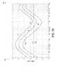
図16は、本明細書で説明する複数のサラウンドプロセッサのいずれかにより実現することができる複数の例示的遠近感曲線1600を示す。これらの遠近感曲線1600は、一実施形態では、図14の遠近感曲線フィルタ1406または1420により実現することができる複数のリア遠近感曲線である。図15のように、入力対数周波数スイープ1610を示し、2つの異なる遠近感曲線フィルタの出力トレース1620、1630をもたらす。
FIG. 16 illustrates a plurality of
一実施形態では、遠近感曲線1620は、サラウンド差信号に適用された遠近感曲線フィルタに対応する。たとえば、遠近感曲線フィルタ1406により遠近感曲線1620を実現することができる。遠近感曲線1620は、ある種の実施形態では、サラウンド和信号に適用された遠近感曲線フィルタに対応する。たとえば、遠近感曲線フィルタ1420により遠近感曲線1630を実現することができる。曲線1620、1630の実効的な大きさは、上述のサラウンドスケール536設定に基づき変わることができる。
In one embodiment, the perspective curve 1620 corresponds to a perspective curve filter applied to the surround difference signal. For example, the perspective curve 1620 can be realized by the perspective curve filter 1406. The perspective curve 1620 corresponds to a perspective curve filter applied to the surround sum signal in certain embodiments. For example, the
より詳細には、図示する例示的実施形態では、曲線1620は、約−10dBFSのほぼ平坦なゲインを有し、このゲインは、約2kHzと約4kHzの間に発生する、またはほぼ2.5kHzと3kHzの間にある谷まで減衰する。この谷から、曲線1620は、ピークが発生する約11kHzまで、または約10kHzと12kHzの間で振幅が増大する。このピークの後、曲線1620は再度、約20kHz以下まで減衰する。曲線1630は、類似の構造を有するが、それほど顕著ではないピークおよび谷を有し、約3kHz(または約2kHzと4kHzの間)にある谷まで平坦な曲線であり、ピークが約11kHz(または約10kHzと12kHzの間)にあり、約20kHz以下まで減衰する。
More particularly, in the illustrated exemplary embodiment, curve 1620 has a substantially flat gain of about −10 dBFS, which occurs between about 2 kHz and about 4 kHz, or is about 2.5 kHz. Attenuates to a valley between 3 kHz. From this trough, the curve 1620 increases in amplitude to about 11 kHz where the peak occurs or between about 10 kHz and 12 kHz. After this peak, curve 1620 again decays to about 20 kHz or less.
図示する曲線は単なる例であり、異なる実施形態では変えることができる。たとえば、複数の曲線と高域フィルタを組み合わせて、平坦な低周波応答を、減衰する低周波応答に変更することができる。 The curves shown are merely examples and can be varied in different embodiments. For example, a plurality of curves and a high pass filter can be combined to change a flat low frequency response to a damped low frequency response.
V.用語
本明細書で説明する以外の多くの変形形態がこの開示から明らかであろう。たとえば、実施形態に応じて、本明細書で説明する複数のアルゴリズムのいずれかのある種の複数の活動、複数のイベント、または複数の機能を、異なる順序で実施することができる、追加する、統合する、または同時に省くことができる(たとえば複数のアルゴリズムの実施のために、説明するすべての活動またはイベントが必要であるわけではない)。さらに、ある種の実施形態では、複数の活動または複数のイベントは、順次にではなく、同時に、たとえば、マルチスレッド処理、割込処理、または複数のプロセッサもしくは複数のプロセッサコアにより、または他の複数の並列アーキテクチャで実施することができる。さらに、一緒に機能することができる、異なる複数の機械および/または複数のコンピューティングシステムにより、異なる複数のタスクまたは複数の処理を実施することができる。
V. Terminology Many variations other than those described herein will be apparent from this disclosure. For example, depending on the embodiment, certain types of activities, events, or functions of any of the algorithms described herein may be performed in a different order, adding, Can be integrated or omitted at the same time (eg, not all activities or events described are required for implementation of multiple algorithms). Further, in certain embodiments, multiple activities or multiple events are not sequentially but simultaneously, eg, by multi-threaded processing, interrupt processing, or multiple processors or multiple processor cores, or other multiple Can be implemented in parallel architectures. Further, different tasks or processes can be performed by different machines and / or multiple computing systems that can function together.
本明細書で開示する実施形態に関連して説明する、さまざまな複数の例示的論理ブロック、複数のモジュール、および複数のアルゴリズムステップを、電子回路ハードウェア、コンピュータソフトウェア、または両方の組合せとして実現することができる。ハードウェアおよびソフトウェアのこの互換性を明確に示すために、さまざまな例示的構成要素、ブロック、モジュール、およびステップについて、一般にこれらの機能に関して上記で説明した。このような機能がハードウェアまたはソフトウェアとして実現されるかどうかは、システム全体に課された特定の用途および設計の複数の制約に依存する。説明する機能を、それぞれの特定の用途についてさまざまな方法で実現することができるが、このような実現の複数の決定が、本開示の範囲からの逸脱を引き起こすと解釈されるべきではない。 The various illustrative logic blocks, modules, and algorithm steps described in connection with the embodiments disclosed herein are implemented as electronic circuit hardware, computer software, or a combination of both. be able to. To clearly illustrate this interchangeability of hardware and software, various illustrative components, blocks, modules, and steps have been described above generally in terms of their functionality. Whether such functionality is implemented as hardware or software depends on the particular application and design constraints imposed on the overall system. The functions described can be implemented in a variety of ways for each particular application, but multiple decisions of such implementations should not be construed as causing deviations from the scope of this disclosure.
本明細書で開示する実施形態に関連して説明するさまざまな例示的論理ブロックおよびモジュールを、機械により、たとえば、汎用プロセッサ、デジタル・シグナル・プロセッサ(DSP)、特定用途向け集積回路(ASIC)、フィールド・プログラマブル・ゲート・アレイ(FPGA)もしくは他のプログラム可能論理デバイス、ディスクリートのゲートもしくはトランジスタ論理回路、ディスクリートの複数のハードウェア構成要素、または本明細書で説明する複数の機能を実施するように設計されたこれらの任意の組合せにより実現または実施することができる。汎用プロセッサをマイクロプロセッサとすることができるが、代替形態では、プロセッサを、コントローラ、マイクロコントローラ、もしくは状態機械、これらの組合せ、または同種のものとすることができる。また、プロセッサを、複数のコンピューティングデバイスの組合せとして、たとえば、DSPとマイクロプロセッサの組合せ、複数のマイクロプロセッサ、DSPコアと1つまたは複数のマイクロプロセッサとの併用、または任意の他のこのような構成として実現することができる。デジタル技術に関して本明細書で主に説明するが、プロセッサが、同じく主にアナログ構成要素を含んでもよい。たとえば、本明細書で説明する複数の信号処理アルゴリズムのいずれも、アナログ回路で実現されてもよい。コンピューティング環境が、少し例を挙げると、マイクロプロセッサに基づくコンピュータシステム、メインフレームコンピュータ、デジタル・シグナル・プロセッサ、携帯型コンピューティングデバイス、パーソナルオーガナイザ、デバイスコントローラ、および設備内部の計算エンジンを含むがこれらに限定されない、任意のタイプのコンピュータシステムを含むことができる。 Various exemplary logic blocks and modules described in connection with the embodiments disclosed herein can be machined, for example, by a general purpose processor, a digital signal processor (DSP), an application specific integrated circuit (ASIC), A field programmable gate array (FPGA) or other programmable logic device, discrete gate or transistor logic, multiple hardware components, or multiple functions described herein It can be realized or implemented by any combination of these designed. A general purpose processor may be a microprocessor, but in the alternative, the processor may be a controller, microcontroller, or state machine, combinations of these, or the like. The processor may also be a combination of multiple computing devices, such as a combination of a DSP and a microprocessor, a plurality of microprocessors, a combination of a DSP core and one or more microprocessors, or any other such It can be realized as a configuration. Although primarily described herein with respect to digital technology, a processor may also include primarily analog components. For example, any of the plurality of signal processing algorithms described herein may be implemented with an analog circuit. Computing environments include microprocessor-based computer systems, mainframe computers, digital signal processors, portable computing devices, personal organizers, device controllers, and computing engines inside facilities, to name a few. Any type of computer system, including but not limited to, can be included.
本明細書で開示する実施形態に関連して説明する、方法、処理、またはアルゴリズムの複数のステップを、ハードウェアで、プロセッサにより実行されるソフトウェアモジュールで、または両方の組合せで直接具体化することができる。ソフトウェアモジュールは、RAMメモリ、フラッシュメモリ、ROMメモリ、EPROMメモリ、EEPROMメモリ、レジスタ、ハードディスク、取り外し可能ディスク、CD−ROM、または任意の他の形態の非一時的コンピュータ可読媒体、メディア、もしくは当技術分野で公知の物理的コンピュータ記憶装置に常駐することができる。プロセッサが記憶媒体から情報を読み出し、記憶装置に情報を書き込むことができるように、例示的記憶媒体をプロセッサに結合することができる。代替形態では、記憶媒体をプロセッサに一体化することができる。プロセッサおよび記憶媒体は、ASICに常駐することができる。ASICはユーザ端末に常駐することができる。代替形態では、プロセッサおよび記憶媒体は、ユーザ端末に別個の構成要素として常駐することができる。 Directly embodying the steps of the methods, processes, or algorithms described in connection with the embodiments disclosed herein in hardware, in software modules executed by a processor, or in a combination of both Can do. A software module may be RAM memory, flash memory, ROM memory, EPROM memory, EEPROM memory, registers, hard disk, removable disk, CD-ROM, or any other form of non-transitory computer readable media, media, or technology It can reside on physical computer storage devices known in the art. An exemplary storage medium can be coupled to the processor such that the processor can read information from, and write information to, the storage device. In the alternative, the storage medium may be integral to the processor. The processor and the storage medium can reside in an ASIC. The ASIC can reside in the user terminal. In the alternative, the processor and the storage medium may reside as discrete components in a user terminal.
本明細書で使用する、条件を表す言葉、たとえば、とりわけ「can」、「might」、「may」、「e.g.」などは、具体的に他の方法で明言されない場合、または使用されるときに文脈の中で他の方法で理解されない場合、一般に、ある種の複数の特徴、複数の要素、および/または複数の状態を、ある種の実施形態が含むが、他の実施形態が含まないことを伝えることが意図される。したがって、このような条件を表す言葉は、一般に、複数の特徴、複数の要素、および/または複数の状態が、1つまたは複数の実施形態で、任意の方法で必要とされること、またはこれらの特徴、要素、および/または状態が含まれるにせよ、任意の特定の実施形態で実現されるはずであるにせよ、いずれにしても、1つまたは複数の実施形態が、作成者の入力または催促ありまたはなしで、決定を下すための論理回路を必ず含むことを意味することが意図されない。用語「comprising」、「including」、「having」などは、同義語であり、非限定的なやり方で包括的に使用され、追加の複数の要素、複数の特徴、複数の活動、複数の動作などを排除しない。また、用語「or」は、(排他的な意味ではなく)包括的な意味で使用され、その結果、たとえば複数の要素のリストを連結するために使用されたときに、用語「or」は、リスト内の複数の要素のうち1つ、いくつか、またはすべてを意味する。 As used herein, terms describing conditions, such as “can”, “might”, “may”, “eg”, among others, are used or used unless specifically stated otherwise. In general, certain embodiments include certain features, elements, and / or states, although other embodiments may not be understood in context otherwise. It is intended to convey that it is not included. Accordingly, the terminology used to describe such conditions generally means that multiple features, multiple elements, and / or multiple states are required in any way in one or more embodiments, or In any case, one or more embodiments may be input by the author, or may be implemented in any particular embodiment, regardless of features, elements, and / or states of It is not meant to imply including logic for making decisions, with or without reminders. The terms “comprising”, “including”, “having”, etc. are synonyms and are used in a non-limiting manner in an inclusive manner, additional elements, features, activities, actions, etc. Do not exclude. Also, the term “or” is used in a comprehensive sense (rather than an exclusive sense), so that when used, for example, to concatenate lists of elements, the term “or” Means one, some, or all of the elements in the list.
上記の詳細な説明が、さまざまな実施形態に適用されるような新規な複数の特徴を示し、説明し、指摘したが、本開示の精神を逸脱することなく、示される複数のデバイスまたは複数のアルゴリズムの形態および詳細に、さまざまな省略、置換、および変更を行うことができることを理解されよう。理解されるように、いくつかの特徴が他とは別個に使用または実施することができるので、本明細書で示す複数の特徴および複数の利益のすべてを提供するわけではない形態の範囲内で、本明細書で説明する本発明のある種の実施形態を具体化することができる。
以下に、本願出願時の特許請求の範囲に記載された発明を付記する。
[1] オーディオ信号に適用される遠近感拡張を変調する方法であって、
前記方法は、
リスナを基準にして音源の空間的位置に関する情報をそれぞれ備える左および右のオーディオ信号を受信することと、
前記左および右のオーディオ信号の差情報を計算することと、
左および右の出力信号をもたらすように、前記左および右のオーディオ信号の差情報に少なくとも1つの遠近感フィルタを適用することと、
前記左および右の出力信号に、前記計算された情報に少なくとも一部は基づくゲインの値を適用することと、
を備え、
前記ゲインを少なくとも前記適用することは、1つまたは複数のプロセッサにより実施される方法。
[2] 前記差情報の包絡線を検出することおよび前記差信号を平滑化することのうち1つまたは複数を実施することをさらに備える、前記[1]に記載の方法。
[3] 前記変調することは、前記差情報の前記包絡線および前記平滑化された差情報のうちの一方または両方に少なくとも一部は基づき、前記少なくとも1つの遠近感フィルタの前記適用を変調することを備える、前記[2]に記載の方法。
[4] 前記左および右のオーディオ信号の複数の信号レベルに少なくとも一部は基づき、前記差情報を正規化することをさらに備える、前記[1]、[2]、または[3]に記載の方法。
[5] 前記変調することは、前記正規化された差情報に少なくとも一部は基づき、前記少なくとも1つの遠近感フィルタの前記適用を変調することを備える、前記[4]に記載の方法。
[6] 前記正規化することは、前記左および右のオーディオ信号の幾何平均を計算することと、前記計算された幾何平均で前記差情報を除算することと、を備える、前記[4]または[5]に記載の方法。
[7] 前記左および右の出力信号にクロストークキャンセルを適用して、バックウェーブクロストークを低減することをさらに備える、前記[1]から[6]のいずれかに記載の方法。
[8] 前記少なくとも1つの遠近感フィルタを適用することの前に、前記差情報に少なくとも一部は基づき、前記左および右のオーディオ信号に深度レンダリング拡張を適用することをさらに備える、前記[1]から[7]のいずれかに記載の方法。
[9] 前記左および右のオーディオ信号に前記深度レンダリング拡張を前記適用することは、前記左および右のオーディオ信号を脱相関することを備える、前記[8]に記載の方法。
[10] オーディオ信号に適用される遠近感拡張を変調するシステムであって、
前記システムは、
リスナを基準にして音源の空間的位置に関する情報をそれぞれ備える左および右のオーディオ信号を受信すること、および
前記左および右のオーディオ信号から差信号を得ること
に少なくともより、複数のオーディオ信号を解析するように構成された信号解析構成要素と、
少なくとも1つの遠近感フィルタを前記差信号に適用して、左および右の出力信号をもたらすように構成された、1つまたは複数の物理的プロセッサを備えるサラウンドプロセッサと、
を備え、前記少なくとも1つの遠近感フィルタの出力が、前記計算された差情報に少なくとも一部は基づき変調されるシステム。
[11] 前記信号解析器は、前記差信号の包絡線を検出することおよび前記差信号を平滑化することのうち1つまたは複数を少なくとも実施するようにさらに構成される、前記[10]に記載のシステム。
[12] 前記サラウンドプロセッサは、前記差信号の前記包絡線および前記平滑化された差信号のうちの一方または両方に少なくとも一部は基づき、前記変調を実施するように構成される、前記[11]に記載のシステム。
[13] 前記信号解析器は、前記左および右のオーディオ信号の複数の信号レベルに少なくとも一部は基づき、前記差信号を正規化するようにさらに構成される、前記[10]、[11]、または[12]に記載のシステム。
[14] 前記サラウンドプロセッサは、前記正規化された差信号に少なくとも一部は基づき、前記変調を実施するようにさらに構成される、前記[13]に記載のシステム。
[15] 前記信号解析器は、少なくとも、前記左および右のオーディオ信号の幾何平均を少なくとも計算すること、および前記計算された幾何平均で前記差信号を除算することにより、前記差信号を正規化するようにさらに構成される、前記[13]または[14]に記載のシステム。
[16] 前記左および右の出力信号にクロストークキャンセルを適用するように構成されたクロストークキャンセラをさらに備える、前記[10]から[15]のいずれか一項に記載のシステム。
[17] 前記少なくとも1つの遠近感フィルタを適用する前に、前記差信号に少なくとも一部は基づき、前記左および右のオーディオ信号に深度をレンダリングするように構成された深度レンダリング構成要素をさらに備える、前記[10]から[16]のいずれか一項に記載のシステム。
[18] 前記深度レンダリング構成要素は、前記左および右のオーディオ信号を少なくとも脱相関することにより、前記深度をレンダリングするようにさらに構成される、前記[17]に記載のシステム。
[19] 1つまたは複数のプロセッサ内で、オーディオ信号に適用される遠近感拡張を変調するための複数の動作を実施するように構成された、中に記憶された複数の命令を備える非一時的な物理的コンピュータ記憶装置であって、前記複数の動作は、
リスナを基準にして音源の空間的位置に関する情報をそれぞれ備える左および右のオーディオ信号を受信することと、
前記左および右のオーディオ信号の差情報を計算することと、
左および右の出力信号をもたらすように、記左および右のオーディオ信号の各々に少なくとも1つの遠近感フィルタを適用することと、
前記計算された差情報に少なくとも一部は基づき、前記少なくとも1つの遠近感フィルタの前記適用を変調することと、
を備える非一時的な物理的コンピュータ記憶装置。
[20] オーディオ信号に適用される遠近感拡張を変調するシステムであって、
前記システムは、
リスナを基準にして音源の空間的位置に関する情報をそれぞれ備える左および右のオーディオ信号を受信するための手段と、
前記左および右のオーディオ信号の差情報を計算するための手段と、
左および右の出力信号をもたらすように、前記左および右のオーディオ信号の各々に少なくとも1つの遠近感フィルタを適用するための手段と、
前記計算された差情報に少なくとも一部は基づき、前記少なくとも1つの遠近感フィルタの前記適用を変調するための手段と、
を備えるシステム。
Although the foregoing detailed description has shown, described, and pointed out novel features as applied to various embodiments, it is understood that without departing from the spirit of the present disclosure, the illustrated devices or devices It will be appreciated that various omissions, substitutions, and changes may be made to the algorithm form and details. As will be appreciated, some features may be used or implemented separately from the others, and thus within the scope of the forms that do not provide all of the features and benefits shown herein. Certain embodiments of the invention described herein can be embodied.
The invention described in the scope of claims at the time of filing the present application will be appended.
[1] A method of modulating a perspective extension applied to an audio signal,
The method
Receiving left and right audio signals, each comprising information about the spatial position of the sound source relative to the listener;
Calculating difference information between the left and right audio signals;
Applying at least one perspective filter to the difference information of the left and right audio signals to provide a left and right output signal;
Applying gain values to the left and right output signals based at least in part on the calculated information;
With
The method wherein at least the applying the gain is performed by one or more processors.
[2] The method according to [1], further comprising performing one or more of detecting an envelope of the difference information and smoothing the difference signal.
[3] The modulating modulates the application of the at least one perspective filter based at least in part on one or both of the envelope of the difference information and the smoothed difference information. The method according to [2] above, comprising:
[4] The method according to [1], [2], or [3], further comprising normalizing the difference information based at least in part on a plurality of signal levels of the left and right audio signals. Method.
[5] The method of [4], wherein the modulating comprises modulating the application of the at least one perspective filter based at least in part on the normalized difference information.
[6] The normalization comprises: calculating a geometric mean of the left and right audio signals; and dividing the difference information by the calculated geometric mean. The method according to [5].
[7] The method according to any one of [1] to [6], further comprising applying crosstalk cancellation to the left and right output signals to reduce backwave crosstalk.
[8] Prior to applying the at least one perspective filter, the method further comprises applying a depth rendering extension to the left and right audio signals based at least in part on the difference information. ] To [7].
[9] The method of [8], wherein the applying the depth rendering extension to the left and right audio signals comprises decorrelating the left and right audio signals.
[10] A system for modulating a perspective extension applied to an audio signal,
The system
Receiving left and right audio signals, each comprising information about the spatial position of the sound source relative to the listener; and
Obtaining a difference signal from the left and right audio signals;
A signal analysis component configured to analyze at least a plurality of audio signals; and
A surround processor comprising one or more physical processors configured to apply at least one perspective filter to the difference signal to provide left and right output signals;
And the output of the at least one perspective filter is modulated based at least in part on the calculated difference information.
[11] In the above [10], the signal analyzer is further configured to perform at least one or more of detecting an envelope of the difference signal and smoothing the difference signal The described system.
[12] The surround processor is configured to perform the modulation based at least in part on one or both of the envelope of the difference signal and the smoothed difference signal. ] The system described in.
[13] The signal analyzer is further configured to normalize the difference signal based at least in part on a plurality of signal levels of the left and right audio signals. Or the system according to [12].
[14] The system of [13], wherein the surround processor is further configured to perform the modulation based at least in part on the normalized difference signal.
[15] The signal analyzer normalizes the difference signal by calculating at least a geometric mean of the left and right audio signals and dividing the difference signal by the calculated geometric mean. The system according to [13] or [14], further configured to:
[16] The system according to any one of [10] to [15], further including a crosstalk canceller configured to apply crosstalk cancellation to the left and right output signals.
[17] A depth rendering component configured to render depth in the left and right audio signals based at least in part on the difference signal before applying the at least one perspective filter The system according to any one of [10] to [16].
[18] The system of [17], wherein the depth rendering component is further configured to render the depth by at least decorrelating the left and right audio signals.
[19] A non-transitory comprising a plurality of instructions stored therein configured to perform a plurality of operations for modulating a perspective extension applied to an audio signal within one or more processors. A physical computer storage device, wherein the plurality of operations are:
Receiving left and right audio signals, each comprising information about the spatial position of the sound source relative to the listener;
Calculating difference information between the left and right audio signals;
Applying at least one perspective filter to each of the left and right audio signals to provide a left and right output signal;
Modulating the application of the at least one perspective filter based at least in part on the calculated difference information;
A non-transitory physical computer storage device.
[20] A system for modulating a perspective extension applied to an audio signal,
The system
Means for receiving left and right audio signals, each comprising information about the spatial position of the sound source relative to the listener;
Means for calculating difference information of the left and right audio signals;
Means for applying at least one perspective filter to each of the left and right audio signals to provide a left and right output signal;
Means for modulating the application of the at least one perspective filter based at least in part on the calculated difference information;
A system comprising:
Claims (16)
前記方法は、
リスナを基準にして音源の空間的位置に関する情報をそれぞれ備える左および右のオーディオ信号を受信することと、
前記左および右のオーディオ信号の差情報を計算することと、
左および右の出力信号をもたらすように、前記左および右のオーディオ信号の差情報に少なくとも1つの遠近感フィルタを適用することと、
前記左および右の出力信号に、前記計算された情報に少なくとも一部は基づくゲインの値を適用することと、
を備え、
前記ゲインを少なくとも前記適用することは、1つまたは複数のプロセッサにより実施される方法。 A method of modulating a perspective extension applied to an audio signal, comprising:
The method
Receiving left and right audio signals, each comprising information about the spatial position of the sound source relative to the listener;
Calculating difference information between the left and right audio signals;
Applying at least one perspective filter to the difference information of the left and right audio signals to provide a left and right output signal;
Applying gain values to the left and right output signals based at least in part on the calculated information;
With
The method wherein at least the applying the gain is performed by one or more processors.
前記システムは、
リスナを基準にして音源の空間的位置に関する情報をそれぞれ備える左および右のオーディオ信号を受信すること、および
前記左および右のオーディオ信号から差信号を得ること
に少なくともより、複数のオーディオ信号を解析するように構成された信号解析構成要素と、
少なくとも1つの遠近感フィルタを前記差信号に適用して、左および右の出力信号をもたらすように構成された、1つまたは複数の物理的プロセッサを備えるサラウンドプロセッサと、
を備え、前記少なくとも1つの遠近感フィルタの出力が、前記計算された差信号に少なくとも一部は基づき変調されるシステム。 A system for modulating the perspective extension applied to an audio signal,
The system
Analyzing multiple audio signals at least by receiving left and right audio signals, each with information about the spatial location of the sound source relative to the listener, and obtaining a difference signal from the left and right audio signals A signal analysis component configured to:
A surround processor comprising one or more physical processors configured to apply at least one perspective filter to the difference signal to provide left and right output signals;
And the output of the at least one perspective filter is modulated based at least in part on the calculated difference signal .
Applications Claiming Priority (3)
| Application Number | Priority Date | Filing Date | Title |
|---|---|---|---|
| US201161429600P | 2011-01-04 | 2011-01-04 | |
| US61/429,600 | 2011-01-04 | ||
| PCT/US2012/020099 WO2012094335A1 (en) | 2011-01-04 | 2012-01-03 | Immersive audio rendering system |
Publications (2)
| Publication Number | Publication Date |
|---|---|
| JP2014505427A JP2014505427A (en) | 2014-02-27 |
| JP5955862B2 true JP5955862B2 (en) | 2016-07-20 |
Family
ID=46380804
Family Applications (1)
| Application Number | Title | Priority Date | Filing Date |
|---|---|---|---|
| JP2013548464A Active JP5955862B2 (en) | 2011-01-04 | 2012-01-03 | Immersive audio rendering system |
Country Status (6)
| Country | Link |
|---|---|
| US (3) | US9154897B2 (en) |
| EP (1) | EP2661907B8 (en) |
| JP (1) | JP5955862B2 (en) |
| KR (1) | KR101827036B1 (en) |
| CN (1) | CN103329571B (en) |
| WO (2) | WO2012094338A1 (en) |
Families Citing this family (50)
| Publication number | Priority date | Publication date | Assignee | Title |
|---|---|---|---|---|
| CN103329571B (en) * | 2011-01-04 | 2016-08-10 | Dts有限责任公司 | Immersion audio presentation systems |
| CN103188503A (en) * | 2011-12-29 | 2013-07-03 | 三星电子株式会社 | Display apparatus and method for controlling thereof |
| TWI479905B (en) * | 2012-01-12 | 2015-04-01 | Univ Nat Central | Multi-channel down mixing device |
| EP2811763A4 (en) * | 2012-02-03 | 2015-06-17 | Panasonic Ip Man Co Ltd | Surround component generator |
| US9264840B2 (en) * | 2012-05-24 | 2016-02-16 | International Business Machines Corporation | Multi-dimensional audio transformations and crossfading |
| US9332373B2 (en) * | 2012-05-31 | 2016-05-03 | Dts, Inc. | Audio depth dynamic range enhancement |
| CN103686136A (en) * | 2012-09-18 | 2014-03-26 | 宏碁股份有限公司 | Multimedia processing system and audio signal processing method |
| US9774973B2 (en) * | 2012-12-04 | 2017-09-26 | Samsung Electronics Co., Ltd. | Audio providing apparatus and audio providing method |
| US9264838B2 (en) | 2012-12-27 | 2016-02-16 | Dts, Inc. | System and method for variable decorrelation of audio signals |
| WO2014190140A1 (en) | 2013-05-23 | 2014-11-27 | Alan Kraemer | Headphone audio enhancement system |
| CN105378826B (en) | 2013-05-31 | 2019-06-11 | 诺基亚技术有限公司 | Audio scene device |
| US9858932B2 (en) | 2013-07-08 | 2018-01-02 | Dolby Laboratories Licensing Corporation | Processing of time-varying metadata for lossless resampling |
| RU2716037C2 (en) | 2013-07-31 | 2020-03-05 | Долби Лэборетериз Лайсенсинг Корпорейшн | Processing of spatially-diffuse or large sound objects |
| CN109040946B (en) * | 2013-10-31 | 2021-09-14 | 杜比实验室特许公司 | Binaural rendering of headphones using metadata processing |
| BR112016022042B1 (en) * | 2014-03-24 | 2022-09-27 | Samsung Electronics Co., Ltd | METHOD FOR RENDERING AN AUDIO SIGNAL, APPARATUS FOR RENDERING AN AUDIO SIGNAL, AND COMPUTER READABLE RECORDING MEDIUM |
| US9837061B2 (en) * | 2014-06-23 | 2017-12-05 | Nxp B.V. | System and method for blending multi-channel signals |
| US9384745B2 (en) * | 2014-08-12 | 2016-07-05 | Nxp B.V. | Article of manufacture, system and computer-readable storage medium for processing audio signals |
| EP3201916B1 (en) | 2014-10-01 | 2018-12-05 | Dolby International AB | Audio encoder and decoder |
| KR102486338B1 (en) | 2014-10-31 | 2023-01-10 | 돌비 인터네셔널 에이비 | Parametric encoding and decoding of multichannel audio signals |
| CN106999788A (en) | 2014-11-30 | 2017-08-01 | 杜比实验室特许公司 | The large format theater design of social media link |
| US9551161B2 (en) | 2014-11-30 | 2017-01-24 | Dolby Laboratories Licensing Corporation | Theater entrance |
| US20160171987A1 (en) * | 2014-12-16 | 2016-06-16 | Psyx Research, Inc. | System and method for compressed audio enhancement |
| US10187737B2 (en) | 2015-01-16 | 2019-01-22 | Samsung Electronics Co., Ltd. | Method for processing sound on basis of image information, and corresponding device |
| CN106303897A (en) | 2015-06-01 | 2017-01-04 | 杜比实验室特许公司 | Process object-based audio signal |
| CN105101039B (en) * | 2015-08-31 | 2018-12-18 | 广州酷狗计算机科技有限公司 | Stereo restoring method and device |
| US10045145B2 (en) * | 2015-12-18 | 2018-08-07 | Qualcomm Incorporated | Temporal offset estimation |
| JP6479287B1 (en) | 2016-01-18 | 2019-03-06 | ブームクラウド 360 インコーポレイテッド | Subband space crosstalk cancellation for audio playback |
| US10225657B2 (en) | 2016-01-18 | 2019-03-05 | Boomcloud 360, Inc. | Subband spatial and crosstalk cancellation for audio reproduction |
| EP3453190A4 (en) | 2016-05-06 | 2020-01-15 | DTS, Inc. | Immersive audio reproduction systems |
| US10057681B2 (en) * | 2016-08-01 | 2018-08-21 | Bose Corporation | Entertainment audio processing |
| CN114466279A (en) * | 2016-11-25 | 2022-05-10 | 索尼公司 | Reproducing method, reproducing apparatus, reproducing medium, information processing method, and information processing apparatus |
| JP2020508590A (en) * | 2017-02-17 | 2020-03-19 | アンビディオ,インコーポレイテッド | Apparatus and method for downmixing multi-channel audio signals |
| US10979844B2 (en) | 2017-03-08 | 2021-04-13 | Dts, Inc. | Distributed audio virtualization systems |
| GB2561595A (en) * | 2017-04-20 | 2018-10-24 | Nokia Technologies Oy | Ambience generation for spatial audio mixing featuring use of original and extended signal |
| WO2018200000A1 (en) | 2017-04-28 | 2018-11-01 | Hewlett-Packard Development Company, L.P. | Immersive audio rendering |
| US10602296B2 (en) | 2017-06-09 | 2020-03-24 | Nokia Technologies Oy | Audio object adjustment for phase compensation in 6 degrees of freedom audio |
| CN111587582B (en) * | 2017-10-18 | 2022-09-02 | Dts公司 | System, method, and storage medium for audio signal preconditioning for 3D audio virtualization |
| US10524078B2 (en) * | 2017-11-29 | 2019-12-31 | Boomcloud 360, Inc. | Crosstalk cancellation b-chain |
| US10609504B2 (en) * | 2017-12-21 | 2020-03-31 | Gaudi Audio Lab, Inc. | Audio signal processing method and apparatus for binaural rendering using phase response characteristics |
| KR20190083863A (en) * | 2018-01-05 | 2019-07-15 | 가우디오랩 주식회사 | A method and an apparatus for processing an audio signal |
| US10764704B2 (en) * | 2018-03-22 | 2020-09-01 | Boomcloud 360, Inc. | Multi-channel subband spatial processing for loudspeakers |
| WO2019191611A1 (en) * | 2018-03-29 | 2019-10-03 | Dts, Inc. | Center protection dynamic range control |
| KR102531634B1 (en) | 2018-08-10 | 2023-05-11 | 삼성전자주식회사 | Audio apparatus and method of controlling the same |
| CN109348390B (en) * | 2018-09-14 | 2021-07-16 | 张小夫 | Realization method of immersive panoramic acoustic electronic music diffusion system |
| US10887720B2 (en) * | 2018-10-05 | 2021-01-05 | Magic Leap, Inc. | Emphasis for audio spatialization |
| CN111757239B (en) * | 2019-03-28 | 2021-11-19 | 瑞昱半导体股份有限公司 | Audio processing method and audio processing system |
| US11026037B2 (en) * | 2019-07-18 | 2021-06-01 | International Business Machines Corporation | Spatial-based audio object generation using image information |
| US11270712B2 (en) | 2019-08-28 | 2022-03-08 | Insoundz Ltd. | System and method for separation of audio sources that interfere with each other using a microphone array |
| US10841728B1 (en) | 2019-10-10 | 2020-11-17 | Boomcloud 360, Inc. | Multi-channel crosstalk processing |
| US11533560B2 (en) | 2019-11-15 | 2022-12-20 | Boomcloud 360 Inc. | Dynamic rendering device metadata-informed audio enhancement system |
Family Cites Families (181)
| Publication number | Priority date | Publication date | Assignee | Title |
|---|---|---|---|---|
| US3249696A (en) | 1961-10-16 | 1966-05-03 | Zenith Radio Corp | Simplified extended stereo |
| US3229038A (en) | 1961-10-31 | 1966-01-11 | Rca Corp | Sound signal transforming system |
| US3246081A (en) | 1962-03-21 | 1966-04-12 | William C Edwards | Extended stereophonic systems |
| FI35014A (en) | 1962-12-13 | 1965-05-10 | sound system | |
| US3170991A (en) | 1963-11-27 | 1965-02-23 | Glasgal Ralph | System for stereo separation ratio control, elimination of cross-talk and the like |
| JPS4312585Y1 (en) | 1965-12-17 | 1968-05-30 | ||
| US3892624A (en) | 1970-02-03 | 1975-07-01 | Sony Corp | Stereophonic sound reproducing system |
| US3665105A (en) | 1970-03-09 | 1972-05-23 | Univ Leland Stanford Junior | Method and apparatus for simulating location and movement of sound |
| US3757047A (en) | 1970-05-21 | 1973-09-04 | Sansui Electric Co | Four channel sound reproduction system |
| CA942198A (en) | 1970-09-15 | 1974-02-19 | Kazuho Ohta | Multidimensional stereophonic reproducing system |
| NL172815B (en) | 1971-04-13 | Sony Corp | MULTIPLE SOUND DISPLAY DEVICE. | |
| US3761631A (en) | 1971-05-17 | 1973-09-25 | Sansui Electric Co | Synthesized four channel sound using phase modulation techniques |
| US3697692A (en) | 1971-06-10 | 1972-10-10 | Dynaco Inc | Two-channel,four-component stereophonic system |
| US3772479A (en) | 1971-10-19 | 1973-11-13 | Motorola Inc | Gain modified multi-channel audio system |
| JPS5313962B2 (en) | 1971-12-21 | 1978-05-13 | ||
| JPS4889702A (en) | 1972-02-25 | 1973-11-22 | ||
| JPS5251764Y2 (en) | 1972-10-13 | 1977-11-25 | ||
| GB1450533A (en) | 1972-11-08 | 1976-09-22 | Ferrograph Co Ltd | Stereo sound reproducing apparatus |
| GB1522599A (en) | 1974-11-16 | 1978-08-23 | Dolby Laboratories Inc | Centre channel derivation for stereophonic cinema sound |
| JPS51144202A (en) | 1975-06-05 | 1976-12-11 | Sony Corp | Stereophonic sound reproduction process |
| JPS5927692B2 (en) | 1975-12-29 | 1984-07-07 | ニホンセキユカガク カブシキガイシヤ | Kanjiyou Film no Seizouhou |
| GB1578854A (en) | 1976-02-27 | 1980-11-12 | Victor Company Of Japan | Stereophonic sound reproduction system |
| JPS52125301A (en) | 1976-04-13 | 1977-10-21 | Victor Co Of Japan Ltd | Signal processing circuit |
| US4063034A (en) | 1976-05-10 | 1977-12-13 | Industrial Research Products, Inc. | Audio system with enhanced spatial effect |
| JPS5927692Y2 (en) | 1976-11-08 | 1984-08-10 | カヤバ工業株式会社 | Control valves for agricultural tractor work equipment and attachments |
| JPS53114201U (en) | 1977-02-18 | 1978-09-11 | ||
| US4209665A (en) | 1977-08-29 | 1980-06-24 | Victor Company Of Japan, Limited | Audio signal translation for loudspeaker and headphone sound reproduction |
| JPS5832840B2 (en) | 1977-09-10 | 1983-07-15 | 日本ビクター株式会社 | 3D sound field expansion device |
| NL7713076A (en) | 1977-11-28 | 1979-05-30 | Johannes Cornelis Maria Van De | METHOD AND DEVICE FOR RECORDING SOUND AND / OR FOR PROCESSING SOUND PRIOR TO PLAYBACK. |
| US4237343A (en) | 1978-02-09 | 1980-12-02 | Kurtin Stephen L | Digital delay/ambience processor |
| US4204092A (en) | 1978-04-11 | 1980-05-20 | Bruney Paul F | Audio image recovery system |
| US4218583A (en) | 1978-07-28 | 1980-08-19 | Bose Corporation | Varying loudspeaker spatial characteristics |
| US4332979A (en) | 1978-12-19 | 1982-06-01 | Fischer Mark L | Electronic environmental acoustic simulator |
| US4239937A (en) | 1979-01-02 | 1980-12-16 | Kampmann Frank S | Stereo separation control |
| US4218585A (en) | 1979-04-05 | 1980-08-19 | Carver R W | Dimensional sound producing apparatus and method |
| US4309570A (en) | 1979-04-05 | 1982-01-05 | Carver R W | Dimensional sound recording and apparatus and method for producing the same |
| JPS55152571U (en) | 1979-04-19 | 1980-11-04 | ||
| JPS6043791B2 (en) | 1979-05-12 | 1985-09-30 | 松下電工株式会社 | Exterior board manufacturing method |
| US4303800A (en) | 1979-05-24 | 1981-12-01 | Analog And Digital Systems, Inc. | Reproducing multichannel sound |
| JPS5931279B2 (en) | 1979-06-19 | 1984-08-01 | 日本ビクター株式会社 | signal conversion circuit |
| JPS56130400U (en) | 1980-03-04 | 1981-10-03 | ||
| US4355203A (en) | 1980-03-12 | 1982-10-19 | Cohen Joel M | Stereo image separation and perimeter enhancement |
| US4356349A (en) | 1980-03-12 | 1982-10-26 | Trod Nossel Recording Studios, Inc. | Acoustic image enhancing method and apparatus |
| US4308423A (en) | 1980-03-12 | 1981-12-29 | Cohen Joel M | Stereo image separation and perimeter enhancement |
| US4308424A (en) | 1980-04-14 | 1981-12-29 | Bice Jr Robert G | Simulated stereo from a monaural source sound reproduction system |
| JPS56163685A (en) | 1980-05-21 | 1981-12-16 | Fukuda Ichikane | Knife |
| JPS575499A (en) | 1980-06-12 | 1982-01-12 | Mitsubishi Electric Corp | Acoustic reproducing device |
| JPS6133600Y2 (en) | 1980-06-17 | 1986-10-01 | ||
| JPS5750800A (en) | 1980-09-12 | 1982-03-25 | Hitachi Ltd | High speed neutral particle device |
| JPS5760800A (en) * | 1980-09-27 | 1982-04-12 | Pioneer Electronic Corp | Tone quality adjusting circuit |
| US4479235A (en) | 1981-05-08 | 1984-10-23 | Rca Corporation | Switching arrangement for a stereophonic sound synthesizer |
| CA1206619A (en) | 1982-01-29 | 1986-06-24 | Frank T. Check, Jr. | Electronic postage meter having redundant memory |
| JPS58144989U (en) | 1982-03-19 | 1983-09-29 | クラリオン株式会社 | audio equipment |
| AT379275B (en) | 1982-04-20 | 1985-12-10 | Neutrik Ag | STEREOPHONE PLAYBACK IN VEHICLE ROOMS OF MOTOR VEHICLES |
| US4489432A (en) | 1982-05-28 | 1984-12-18 | Polk Audio, Inc. | Method and apparatus for reproducing sound having a realistic ambient field and acoustic image |
| US4457012A (en) | 1982-06-03 | 1984-06-26 | Carver R W | FM Stereo apparatus and method |
| US4495637A (en) | 1982-07-23 | 1985-01-22 | Sci-Coustics, Inc. | Apparatus and method for enhanced psychoacoustic imagery using asymmetric cross-channel feed |
| JPS5927692A (en) | 1982-08-04 | 1984-02-14 | Seikosha Co Ltd | Color printer |
| US4497064A (en) | 1982-08-05 | 1985-01-29 | Polk Audio, Inc. | Method and apparatus for reproducing sound having an expanded acoustic image |
| US5412731A (en) * | 1982-11-08 | 1995-05-02 | Desper Products, Inc. | Automatic stereophonic manipulation system and apparatus for image enhancement |
| US4567607A (en) | 1983-05-03 | 1986-01-28 | Stereo Concepts, Inc. | Stereo image recovery |
| US4503554A (en) | 1983-06-03 | 1985-03-05 | Dbx, Inc. | Stereophonic balance control system |
| DE3331352A1 (en) | 1983-08-31 | 1985-03-14 | Blaupunkt-Werke Gmbh, 3200 Hildesheim | Circuit arrangement and process for optional mono and stereo sound operation of audio and video radio receivers and recorders |
| JPS60107998A (en) | 1983-11-16 | 1985-06-13 | Nissan Motor Co Ltd | Acoustic device for automobile |
| US4589129A (en) | 1984-02-21 | 1986-05-13 | Kintek, Inc. | Signal decoding system |
| US4594730A (en) | 1984-04-18 | 1986-06-10 | Rosen Terry K | Apparatus and method for enhancing the perceived sound image of a sound signal by source localization |
| JPS60254995A (en) | 1984-05-31 | 1985-12-16 | Pioneer Electronic Corp | On-vehicle sound field correction system |
| JP2514141Y2 (en) | 1984-05-31 | 1996-10-16 | パイオニア株式会社 | In-vehicle sound field correction device |
| US4569074A (en) | 1984-06-01 | 1986-02-04 | Polk Audio, Inc. | Method and apparatus for reproducing sound having a realistic ambient field and acoustic image |
| JPS6133600A (en) | 1984-07-25 | 1986-02-17 | オムロン株式会社 | Vehicle speed regulation mark control system |
| US4594610A (en) | 1984-10-15 | 1986-06-10 | Rca Corporation | Camera zoom compensator for television stereo audio |
| JPS61166696A (en) | 1985-01-18 | 1986-07-28 | 株式会社東芝 | Digital display unit |
| US4703502A (en) | 1985-01-28 | 1987-10-27 | Nissan Motor Company, Limited | Stereo signal reproducing system |
| JPS61166696U (en) * | 1985-04-04 | 1986-10-16 | ||
| US4696036A (en) | 1985-09-12 | 1987-09-22 | Shure Brothers, Inc. | Directional enhancement circuit |
| US4748669A (en) | 1986-03-27 | 1988-05-31 | Hughes Aircraft Company | Stereo enhancement system |
| NL8702200A (en) | 1987-09-16 | 1989-04-17 | Philips Nv | METHOD AND APPARATUS FOR ADJUSTING TRANSFER CHARACTERISTICS TO TWO LISTENING POSITIONS IN A ROOM |
| US4811325A (en) | 1987-10-15 | 1989-03-07 | Personics Corporation | High-speed reproduction facility for audio programs |
| US4893342A (en) | 1987-10-15 | 1990-01-09 | Cooper Duane H | Head diffraction compensated stereo system |
| US5034983A (en) | 1987-10-15 | 1991-07-23 | Cooper Duane H | Head diffraction compensated stereo system |
| JPH0744759B2 (en) | 1987-10-29 | 1995-05-15 | ヤマハ株式会社 | Sound field controller |
| US5144670A (en) | 1987-12-09 | 1992-09-01 | Canon Kabushiki Kaisha | Sound output system |
| US4862502A (en) | 1988-01-06 | 1989-08-29 | Lexicon, Inc. | Sound reproduction |
| DE68921517T2 (en) | 1988-07-20 | 1996-01-25 | Sanyo Electric Co | Sound player. |
| JPH0720319B2 (en) | 1988-08-12 | 1995-03-06 | 三洋電機株式会社 | Center mode control circuit |
| BG60225B2 (en) | 1988-09-02 | 1993-12-30 | Q Sound Ltd | Method and device for sound image formation |
| US5105462A (en) | 1989-08-28 | 1992-04-14 | Qsound Ltd. | Sound imaging method and apparatus |
| US5046097A (en) | 1988-09-02 | 1991-09-03 | Qsound Ltd. | Sound imaging process |
| US5208860A (en) | 1988-09-02 | 1993-05-04 | Qsound Ltd. | Sound imaging method and apparatus |
| JP2522529B2 (en) | 1988-10-31 | 1996-08-07 | 株式会社東芝 | Sound effect device |
| US4866774A (en) | 1988-11-02 | 1989-09-12 | Hughes Aircraft Company | Stero enhancement and directivity servo |
| DE3932858C2 (en) | 1988-12-07 | 1996-12-19 | Onkyo Kk | Stereophonic playback system |
| JPH0623119Y2 (en) | 1989-01-24 | 1994-06-15 | パイオニア株式会社 | Surround stereo playback device |
| US5146507A (en) | 1989-02-23 | 1992-09-08 | Yamaha Corporation | Audio reproduction characteristics control device |
| US5172415A (en) | 1990-06-08 | 1992-12-15 | Fosgate James W | Surround processor |
| US5228085A (en) | 1991-04-11 | 1993-07-13 | Bose Corporation | Perceived sound |
| US5325435A (en) | 1991-06-12 | 1994-06-28 | Matsushita Electric Industrial Co., Ltd. | Sound field offset device |
| US5251260A (en) | 1991-08-07 | 1993-10-05 | Hughes Aircraft Company | Audio surround system with stereo enhancement and directivity servos |
| US5199075A (en) | 1991-11-14 | 1993-03-30 | Fosgate James W | Surround sound loudspeakers and processor |
| EP0563929B1 (en) | 1992-04-03 | 1998-12-30 | Yamaha Corporation | Sound-image position control apparatus |
| US5255326A (en) | 1992-05-18 | 1993-10-19 | Alden Stevenson | Interactive audio control system |
| US5319713A (en) | 1992-11-12 | 1994-06-07 | Rocktron Corporation | Multi dimensional sound circuit |
| US5333201A (en) * | 1992-11-12 | 1994-07-26 | Rocktron Corporation | Multi dimensional sound circuit |
| AU3427393A (en) | 1992-12-31 | 1994-08-15 | Desper Products, Inc. | Stereophonic manipulation apparatus and method for sound image enhancement |
| US5572591A (en) | 1993-03-09 | 1996-11-05 | Matsushita Electric Industrial Co., Ltd. | Sound field controller |
| JPH06269097A (en) | 1993-03-11 | 1994-09-22 | Sony Corp | Acoustic equipment |
| WO1994022278A1 (en) | 1993-03-18 | 1994-09-29 | Central Research Laboratories Limited | Plural-channel sound processing |
| GB2277855B (en) | 1993-05-06 | 1997-12-10 | S S Stereo P Limited | Audio signal reproducing apparatus |
| US5371799A (en) | 1993-06-01 | 1994-12-06 | Qsound Labs, Inc. | Stereo headphone sound source localization system |
| US5400405A (en) | 1993-07-02 | 1995-03-21 | Harman Electronics, Inc. | Audio image enhancement system |
| DE69433258T2 (en) | 1993-07-30 | 2004-07-01 | Victor Company of Japan, Ltd., Yokohama | Surround sound signal processing device |
| KR0135850B1 (en) | 1993-11-18 | 1998-05-15 | 김광호 | Sound reproducing device |
| US5742688A (en) | 1994-02-04 | 1998-04-21 | Matsushita Electric Industrial Co., Ltd. | Sound field controller and control method |
| US5533129A (en) | 1994-08-24 | 1996-07-02 | Gefvert; Herbert I. | Multi-dimensional sound reproduction system |
| JP3276528B2 (en) | 1994-08-24 | 2002-04-22 | シャープ株式会社 | Sound image enlargement device |
| US20030169886A1 (en) | 1995-01-10 | 2003-09-11 | Boyce Roger W. | Method and apparatus for encoding mixed surround sound into a single stereo pair |
| US5799094A (en) | 1995-01-26 | 1998-08-25 | Victor Company Of Japan, Ltd. | Surround signal processing apparatus and video and audio signal reproducing apparatus |
| US5734724A (en) | 1995-03-01 | 1998-03-31 | Nippon Telegraph And Telephone Corporation | Audio communication control unit |
| US5661808A (en) | 1995-04-27 | 1997-08-26 | Srs Labs, Inc. | Stereo enhancement system |
| US5872851A (en) | 1995-09-18 | 1999-02-16 | Harman Motive Incorporated | Dynamic stereophonic enchancement signal processing system |
| US5677957A (en) | 1995-11-13 | 1997-10-14 | Hulsebus; Alan | Audio circuit producing enhanced ambience |
| US5771295A (en) | 1995-12-26 | 1998-06-23 | Rocktron Corporation | 5-2-5 matrix system |
| GB9603236D0 (en) | 1996-02-16 | 1996-04-17 | Adaptive Audio Ltd | Sound recording and reproduction systems |
| US5970152A (en) | 1996-04-30 | 1999-10-19 | Srs Labs, Inc. | Audio enhancement system for use in a surround sound environment |
| US6009178A (en) | 1996-09-16 | 1999-12-28 | Aureal Semiconductor, Inc. | Method and apparatus for crosstalk cancellation |
| US5912976A (en) * | 1996-11-07 | 1999-06-15 | Srs Labs, Inc. | Multi-channel audio enhancement system for use in recording and playback and methods for providing same |
| US5815578A (en) | 1997-01-17 | 1998-09-29 | Aureal Semiconductor, Inc. | Method and apparatus for canceling leakage from a speaker |
| US6009179A (en) | 1997-01-24 | 1999-12-28 | Sony Corporation | Method and apparatus for electronically embedding directional cues in two channels of sound |
| US6721425B1 (en) | 1997-02-07 | 2004-04-13 | Bose Corporation | Sound signal mixing |
| US6711266B1 (en) * | 1997-02-07 | 2004-03-23 | Bose Corporation | Surround sound channel encoding and decoding |
| JP3663461B2 (en) | 1997-03-13 | 2005-06-22 | スリーエス テック カンパニー リミテッド | Frequency selective spatial improvement system |
| US6111958A (en) * | 1997-03-21 | 2000-08-29 | Euphonics, Incorporated | Audio spatial enhancement apparatus and methods |
| US6236730B1 (en) | 1997-05-19 | 2001-05-22 | Qsound Labs, Inc. | Full sound enhancement using multi-input sound signals |
| US6307941B1 (en) | 1997-07-15 | 2001-10-23 | Desper Products, Inc. | System and method for localization of virtual sound |
| US6668061B1 (en) | 1998-11-18 | 2003-12-23 | Jonathan S. Abel | Crosstalk canceler |
| GB9726338D0 (en) | 1997-12-13 | 1998-02-11 | Central Research Lab Ltd | A method of processing an audio signal |
| GB2343347B (en) | 1998-06-20 | 2002-12-31 | Central Research Lab Ltd | A method of synthesising an audio signal |
| US6931134B1 (en) | 1998-07-28 | 2005-08-16 | James K. Waller, Jr. | Multi-dimensional processor and multi-dimensional audio processor system |
| GB2342830B (en) | 1998-10-15 | 2002-10-30 | Central Research Lab Ltd | A method of synthesising a three dimensional sound-field |
| US6507658B1 (en) | 1999-01-27 | 2003-01-14 | Kind Of Loud Technologies, Llc | Surround sound panner |
| US6175631B1 (en) * | 1999-07-09 | 2001-01-16 | Stephen A. Davis | Method and apparatus for decorrelating audio signals |
| US6424719B1 (en) | 1999-07-29 | 2002-07-23 | Lucent Technologies Inc. | Acoustic crosstalk cancellation system |
| IL134979A (en) | 2000-03-09 | 2004-02-19 | Be4 Ltd | System and method for optimization of three-dimensional audio |
| US6944305B2 (en) * | 2001-04-23 | 2005-09-13 | James K Waller | Audio dynamics processing control system |
| US7076071B2 (en) | 2000-06-12 | 2006-07-11 | Robert A. Katz | Process for enhancing the existing ambience, imaging, depth, clarity and spaciousness of sound recordings |
| US7298852B2 (en) | 2001-07-11 | 2007-11-20 | American Technology Corporation | Dynamic power sharing in a multi-channel sound system |
| JP2002191099A (en) * | 2000-09-26 | 2002-07-05 | Matsushita Electric Ind Co Ltd | Signal processor |
| US7254239B2 (en) | 2001-02-09 | 2007-08-07 | Thx Ltd. | Sound system and method of sound reproduction |
| US7257231B1 (en) | 2002-06-04 | 2007-08-14 | Creative Technology Ltd. | Stream segregation for stereo signals |
| US7203323B2 (en) * | 2003-07-25 | 2007-04-10 | Microsoft Corporation | System and process for calibrating a microphone array |
| US6937737B2 (en) | 2003-10-27 | 2005-08-30 | Britannia Investment Corporation | Multi-channel audio surround sound from front located loudspeakers |
| US7522733B2 (en) * | 2003-12-12 | 2009-04-21 | Srs Labs, Inc. | Systems and methods of spatial image enhancement of a sound source |
| US7536017B2 (en) | 2004-05-14 | 2009-05-19 | Texas Instruments Incorporated | Cross-talk cancellation |
| US20050271214A1 (en) | 2004-06-04 | 2005-12-08 | Kim Sun-Min | Apparatus and method of reproducing wide stereo sound |
| US7490044B2 (en) | 2004-06-08 | 2009-02-10 | Bose Corporation | Audio signal processing |
| JP2006101461A (en) | 2004-09-30 | 2006-04-13 | Yamaha Corp | Stereophonic acoustic reproducing apparatus |
| US7853022B2 (en) | 2004-10-28 | 2010-12-14 | Thompson Jeffrey K | Audio spatial environment engine |
| JP4497161B2 (en) | 2004-11-22 | 2010-07-07 | 三菱電機株式会社 | SOUND IMAGE GENERATION DEVICE AND SOUND IMAGE GENERATION PROGRAM |
| TW200627999A (en) | 2005-01-05 | 2006-08-01 | Srs Labs Inc | Phase compensation techniques to adjust for speaker deficiencies |
| US7974417B2 (en) | 2005-04-13 | 2011-07-05 | Wontak Kim | Multi-channel bass management |
| JP4418774B2 (en) | 2005-05-13 | 2010-02-24 | アルパイン株式会社 | Audio apparatus and surround sound generation method |
| CN101053152B (en) | 2005-07-29 | 2010-12-29 | 哈曼国际工业有限公司 | Audio tuning system and method |
| JP4674505B2 (en) | 2005-08-01 | 2011-04-20 | ソニー株式会社 | Audio signal processing method, sound field reproduction system |
| KR100739762B1 (en) | 2005-09-26 | 2007-07-13 | 삼성전자주식회사 | Apparatus and method for cancelling a crosstalk and virtual sound system thereof |
| US9100765B2 (en) | 2006-05-05 | 2015-08-04 | Creative Technology Ltd | Audio enhancement module for portable media player |
| US8619998B2 (en) * | 2006-08-07 | 2013-12-31 | Creative Technology Ltd | Spatial audio enhancement processing method and apparatus |
| JP4835298B2 (en) | 2006-07-21 | 2011-12-14 | ソニー株式会社 | Audio signal processing apparatus, audio signal processing method and program |
| JP2008048324A (en) * | 2006-08-21 | 2008-02-28 | Pioneer Electronic Corp | Automatic panning adjusting apparatus and method |
| WO2008023178A1 (en) | 2006-08-22 | 2008-02-28 | John Usher | Methods and devices for audio upmixing |
| US8050434B1 (en) | 2006-12-21 | 2011-11-01 | Srs Labs, Inc. | Multi-channel audio enhancement system |
| US8705748B2 (en) * | 2007-05-04 | 2014-04-22 | Creative Technology Ltd | Method for spatially processing multichannel signals, processing module, and virtual surround-sound systems |
| JP2008281355A (en) * | 2007-05-08 | 2008-11-20 | Jfe Engineering Kk | Corrosion risk evaluation method, maintenance plan creation method, corrosion risk evaluation program, maintenance plan creation program, corrosion risk evaluation device, and maintenance plan creation device |
| US8064624B2 (en) * | 2007-07-19 | 2011-11-22 | Fraunhofer-Gesellschaft Zur Foerderung Der Angewandten Forschung E.V. | Method and apparatus for generating a stereo signal with enhanced perceptual quality |
| US8829006B2 (en) | 2007-11-22 | 2014-09-09 | Boehringer Ingelheim International Gmbh | Compounds |
| CN101577117B (en) * | 2009-03-12 | 2012-04-11 | 无锡中星微电子有限公司 | Extracting method of accompaniment music and device |
| EP2420050B1 (en) | 2009-04-15 | 2013-04-10 | Fraunhofer-Gesellschaft zur Förderung der angewandten Forschung e.V. | Multichannel echo canceller |
| US8577065B2 (en) * | 2009-06-12 | 2013-11-05 | Conexant Systems, Inc. | Systems and methods for creating immersion surround sound and virtual speakers effects |
| CN101894559B (en) * | 2010-08-05 | 2012-06-06 | 展讯通信(上海)有限公司 | Audio processing method and device thereof |
| EP2630808B1 (en) | 2010-10-20 | 2019-01-02 | DTS, Inc. | Stereo image widening system |
| CN103329571B (en) | 2011-01-04 | 2016-08-10 | Dts有限责任公司 | Immersion audio presentation systems |
| US9107023B2 (en) | 2011-03-18 | 2015-08-11 | Dolby Laboratories Licensing Corporation | N surround |
-
2012
- 2012-01-03 CN CN201280004662.5A patent/CN103329571B/en active Active
- 2012-01-03 JP JP2013548464A patent/JP5955862B2/en active Active
- 2012-01-03 WO PCT/US2012/020102 patent/WO2012094338A1/en active Application Filing
- 2012-01-03 KR KR1020137020526A patent/KR101827036B1/en active IP Right Grant
- 2012-01-03 EP EP12731992.9A patent/EP2661907B8/en active Active
- 2012-01-03 WO PCT/US2012/020099 patent/WO2012094335A1/en active Application Filing
- 2012-01-03 US US13/342,758 patent/US9154897B2/en active Active
- 2012-01-03 US US13/342,743 patent/US9088858B2/en active Active
-
2015
- 2015-07-16 US US14/801,652 patent/US10034113B2/en active Active
Also Published As
| Publication number | Publication date |
|---|---|
| CN103329571B (en) | 2016-08-10 |
| EP2661907A4 (en) | 2016-11-09 |
| EP2661907A1 (en) | 2013-11-13 |
| US10034113B2 (en) | 2018-07-24 |
| JP2014505427A (en) | 2014-02-27 |
| EP2661907B1 (en) | 2019-07-03 |
| CN103329571A (en) | 2013-09-25 |
| US20160044431A1 (en) | 2016-02-11 |
| US9088858B2 (en) | 2015-07-21 |
| WO2012094338A1 (en) | 2012-07-12 |
| US20120170757A1 (en) | 2012-07-05 |
| EP2661907B8 (en) | 2019-08-14 |
| US20120170756A1 (en) | 2012-07-05 |
| KR20130132971A (en) | 2013-12-05 |
| US9154897B2 (en) | 2015-10-06 |
| WO2012094335A1 (en) | 2012-07-12 |
| KR101827036B1 (en) | 2018-02-07 |
Similar Documents
| Publication | Publication Date | Title |
|---|---|---|
| JP5955862B2 (en) | Immersive audio rendering system | |
| KR101341523B1 (en) | Method to generate multi-channel audio signals from stereo signals | |
| JP5964311B2 (en) | Stereo image expansion system | |
| JP2021061631A (en) | Generating binaural audio in response to multi-channel audio using at least one feedback delay network | |
| US11277707B2 (en) | Spatial audio signal manipulation | |
| US10764709B2 (en) | Methods, apparatus and systems for dynamic equalization for cross-talk cancellation | |
| US11750994B2 (en) | Method for generating binaural signals from stereo signals using upmixing binauralization, and apparatus therefor | |
| GB2565747A (en) | Enhancing loudspeaker playback using a spatial extent processed audio signal | |
| US20210051434A1 (en) | Immersive audio rendering | |
| Liitola | Headphone sound externalization | |
| US11665498B2 (en) | Object-based audio spatializer | |
| US11924623B2 (en) | Object-based audio spatializer | |
| US20240056760A1 (en) | Binaural signal post-processing | |
| CN116193196A (en) | Virtual surround sound rendering method, device, equipment and storage medium | |
| JP2023548570A (en) | Audio system height channel up mixing | |
| Bejoy | Virtual surround sound implementation using deccorrelation filters and HRTF |
Legal Events
| Date | Code | Title | Description |
|---|---|---|---|
| A621 | Written request for application examination |
Free format text: JAPANESE INTERMEDIATE CODE: A621 Effective date: 20141225 |
|
| A977 | Report on retrieval |
Free format text: JAPANESE INTERMEDIATE CODE: A971007 Effective date: 20150710 |
|
| A131 | Notification of reasons for refusal |
Free format text: JAPANESE INTERMEDIATE CODE: A131 Effective date: 20150728 |
|
| A601 | Written request for extension of time |
Free format text: JAPANESE INTERMEDIATE CODE: A601 Effective date: 20151023 |
|
| A521 | Request for written amendment filed |
Free format text: JAPANESE INTERMEDIATE CODE: A523 Effective date: 20151126 |
|
| TRDD | Decision of grant or rejection written | ||
| A01 | Written decision to grant a patent or to grant a registration (utility model) |
Free format text: JAPANESE INTERMEDIATE CODE: A01 Effective date: 20160517 |
|
| A61 | First payment of annual fees (during grant procedure) |
Free format text: JAPANESE INTERMEDIATE CODE: A61 Effective date: 20160615 |
|
| R150 | Certificate of patent or registration of utility model |
Ref document number: 5955862 Country of ref document: JP Free format text: JAPANESE INTERMEDIATE CODE: R150 |
|
| R250 | Receipt of annual fees |
Free format text: JAPANESE INTERMEDIATE CODE: R250 |
|
| R250 | Receipt of annual fees |
Free format text: JAPANESE INTERMEDIATE CODE: R250 |
|
| R250 | Receipt of annual fees |
Free format text: JAPANESE INTERMEDIATE CODE: R250 |
|
| R250 | Receipt of annual fees |
Free format text: JAPANESE INTERMEDIATE CODE: R250 |
|
| R250 | Receipt of annual fees |
Free format text: JAPANESE INTERMEDIATE CODE: R250 |