JP5954565B2 - Liquid ejection head and image forming apparatus - Google Patents
Liquid ejection head and image forming apparatus Download PDFInfo
- Publication number
- JP5954565B2 JP5954565B2 JP2012055525A JP2012055525A JP5954565B2 JP 5954565 B2 JP5954565 B2 JP 5954565B2 JP 2012055525 A JP2012055525 A JP 2012055525A JP 2012055525 A JP2012055525 A JP 2012055525A JP 5954565 B2 JP5954565 B2 JP 5954565B2
- Authority
- JP
- Japan
- Prior art keywords
- liquid chamber
- filter member
- common liquid
- liquid
- filter
- Prior art date
- Legal status (The legal status is an assumption and is not a legal conclusion. Google has not performed a legal analysis and makes no representation as to the accuracy of the status listed.)
- Active
Links
Images


Classifications
-
- B—PERFORMING OPERATIONS; TRANSPORTING
- B41—PRINTING; LINING MACHINES; TYPEWRITERS; STAMPS
- B41J—TYPEWRITERS; SELECTIVE PRINTING MECHANISMS, i.e. MECHANISMS PRINTING OTHERWISE THAN FROM A FORME; CORRECTION OF TYPOGRAPHICAL ERRORS
- B41J2/00—Typewriters or selective printing mechanisms characterised by the printing or marking process for which they are designed
- B41J2/005—Typewriters or selective printing mechanisms characterised by the printing or marking process for which they are designed characterised by bringing liquid or particles selectively into contact with a printing material
- B41J2/01—Ink jet
- B41J2/17—Ink jet characterised by ink handling
- B41J2/175—Ink supply systems ; Circuit parts therefor
- B41J2/17563—Ink filters
-
- B—PERFORMING OPERATIONS; TRANSPORTING
- B41—PRINTING; LINING MACHINES; TYPEWRITERS; STAMPS
- B41J—TYPEWRITERS; SELECTIVE PRINTING MECHANISMS, i.e. MECHANISMS PRINTING OTHERWISE THAN FROM A FORME; CORRECTION OF TYPOGRAPHICAL ERRORS
- B41J2/00—Typewriters or selective printing mechanisms characterised by the printing or marking process for which they are designed
- B41J2/005—Typewriters or selective printing mechanisms characterised by the printing or marking process for which they are designed characterised by bringing liquid or particles selectively into contact with a printing material
- B41J2/01—Ink jet
- B41J2/135—Nozzles
- B41J2/14—Structure thereof only for on-demand ink jet heads
- B41J2/14201—Structure of print heads with piezoelectric elements
- B41J2/14274—Structure of print heads with piezoelectric elements of stacked structure type, deformed by compression/extension and disposed on a diaphragm
-
- B—PERFORMING OPERATIONS; TRANSPORTING
- B41—PRINTING; LINING MACHINES; TYPEWRITERS; STAMPS
- B41J—TYPEWRITERS; SELECTIVE PRINTING MECHANISMS, i.e. MECHANISMS PRINTING OTHERWISE THAN FROM A FORME; CORRECTION OF TYPOGRAPHICAL ERRORS
- B41J2/00—Typewriters or selective printing mechanisms characterised by the printing or marking process for which they are designed
- B41J2/005—Typewriters or selective printing mechanisms characterised by the printing or marking process for which they are designed characterised by bringing liquid or particles selectively into contact with a printing material
- B41J2/01—Ink jet
- B41J2/135—Nozzles
- B41J2/14—Structure thereof only for on-demand ink jet heads
- B41J2002/14362—Assembling elements of heads
-
- B—PERFORMING OPERATIONS; TRANSPORTING
- B41—PRINTING; LINING MACHINES; TYPEWRITERS; STAMPS
- B41J—TYPEWRITERS; SELECTIVE PRINTING MECHANISMS, i.e. MECHANISMS PRINTING OTHERWISE THAN FROM A FORME; CORRECTION OF TYPOGRAPHICAL ERRORS
- B41J2/00—Typewriters or selective printing mechanisms characterised by the printing or marking process for which they are designed
- B41J2/005—Typewriters or selective printing mechanisms characterised by the printing or marking process for which they are designed characterised by bringing liquid or particles selectively into contact with a printing material
- B41J2/01—Ink jet
- B41J2/135—Nozzles
- B41J2/14—Structure thereof only for on-demand ink jet heads
- B41J2002/14403—Structure thereof only for on-demand ink jet heads including a filter
Description
本発明は液体吐出ヘッド、画像形成装置に関する。 The present invention relates to a liquid discharge head and an image forming apparatus.
プリンタ、ファクシミリ、複写装置、プロッタ、これらの複合機等の画像形成装置として、例えば液滴を吐出する液体吐出ヘッド(液滴吐出ヘッド)からなる記録ヘッドを用いた液体吐出記録方式の画像形成装置としてインクジェット記録装置などが知られている。 As an image forming apparatus such as a printer, a facsimile, a copying apparatus, a plotter, and a complex machine of these, for example, a liquid discharge recording type image forming apparatus using a recording head composed of a liquid discharge head (droplet discharge head) for discharging droplets An ink jet recording apparatus or the like is known.
液体吐出ヘッドにおいては、吐出させる液体中に異物が混入すると、ノズルに異物が詰まって吐出不能になり、あるいは、ノズルのエッジに異物が付着して吐出された滴が曲がる噴射曲がりが生じるなど、滴吐出不良が発生することから、流路中に液体をろ過するフィルタ部材を設けるようにしている。 In the liquid ejection head, if foreign matter is mixed in the liquid to be ejected, the nozzle is clogged with foreign matter, making it impossible to eject, or foreign matter adheres to the edge of the nozzle, causing ejection bends that cause the ejected droplet to bend, etc. Since a droplet discharge failure occurs, a filter member for filtering the liquid is provided in the flow path.
従来、例えば、第1金属部材と第2金属部材との間にフィルタ部材を挟み持ち、第1金属部材と第2金属部材とをフィルタ部材を介さずに、フィルタ部材を環状に取り囲む接着剤によって互いに接着するものが知られている(特許文献1)。 Conventionally, for example, by an adhesive that sandwiches a filter member between a first metal member and a second metal member and surrounds the filter member in an annular shape without interposing the filter member between the first metal member and the second metal member. What adhere | attaches mutually is known (patent document 1).
ところで、フィルタ部材を2つの部材間に接着剤接合するときに、接着剤がフィルタ領域内に溢れ出すと、フィルタ孔が詰まって、フィルタ機能が低下する。 By the way, when the adhesive member overflows into the filter region when the filter member is bonded between the two members, the filter hole is clogged and the filter function is lowered.
また、フィルタ部材の下流側では気泡が排出されにくくなるため、気泡排出性を高める必要がある。 Moreover, since it becomes difficult for bubbles to be discharged on the downstream side of the filter member, it is necessary to improve the bubble discharging property.
本発明は上記の課題に鑑みてなされたものであり、フィルタ部材を接合する接着剤のフィルタ領域への溢れ出しを防止するとともに、気泡排出性を向上することを目的とする。 The present invention has been made in view of the above problems, and an object of the present invention is to prevent the adhesive that joins the filter members from overflowing into the filter region and to improve the bubble discharge performance.
上記の課題を解決するため、本発明に係る液体吐出ヘッドは、
液滴を吐出する複数のノズルと、
前記ノズルが通じる複数の個別液室と、
前記複数の個別液室に液体を供給する共通液室と、
前記共通液室内で前記液体をろ過するフィルタ部材と、を備え、
前記共通液室を構成する部材は、前記フィルタ部材上流側の第1共通液室部材と、前記フィルタ部材下流側の第2共通液室部材とを、有し、
前記フィルタ部材は、複数の孔が形成された薄肉層と、前記薄肉層の周縁部に設けられた厚肉層と、を有し、
前記フィルタ部材の厚肉層は、前記第1共通液室部材に接合され、
前記フィルタ部材の薄肉層の前記厚肉層を設けた面と反対側の面の周縁部分は、前記第2共通液室部材と接着剤により接合され、
前記フィルタ部材の薄肉層の前記複数の孔のうち、前記第2共通液室部材と接合された周縁部分に設けられた孔の一部又は全部は、前記厚肉層側が露出し、
前記周縁部分に設けられた孔の一部又は全部に、前記接着剤がはみ出している
構成とした。
In order to solve the above-described problem, a liquid discharge head according to the present invention includes:
A plurality of nozzles for discharging droplets;
A plurality of individual liquid chambers through which the nozzle communicates;
A common liquid chamber for supplying a liquid to the plurality of individual liquid chambers;
A filter member for filtering the liquid in the common liquid chamber,
The member constituting the common liquid chamber has a first common liquid chamber member on the upstream side of the filter member, and a second common liquid chamber member on the downstream side of the filter member,
The filter member has a thin layer in which a plurality of holes are formed, and a thick layer provided on a peripheral portion of the thin layer,
The thick layer of the filter member is joined to the first common liquid chamber member,
The peripheral portion of the surface opposite to the surface on which the thick layer of the thin layer of the filter member is provided is bonded to the second common liquid chamber member with an adhesive,
Among the plurality of holes of the thin layer of the filter member, part or all of the holes provided in the peripheral portion joined to the second common liquid chamber member are exposed on the thick layer side,
It was set as the structure which the said adhesive agent protruded into a part or all of the hole provided in the said peripheral part.
請求項1の発明によれば、フィルタ部材を接合する接着剤のフィルタ領域への溢れ出しを防止するとともに、気泡排出性を向上することができる。 According to the first aspect of the present invention, it is possible to prevent the adhesive that joins the filter members from overflowing into the filter region and to improve the bubble discharge performance.
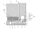
以下、本発明の実施形態について添付図面を参照して説明する。本発明に係る液体吐出ヘッドの第1実施形態について図1ないし図4を参照して説明する。なお、図1は同ヘッドの外観斜視説明図、図2は図1のA―A線に沿うノズル配列方向と直交する方向(液室長手方向)の断面説明図、図3は図1のB−B線に沿うノズル配列方向(液室短手方向)の断面説明図である。 Embodiments of the present invention will be described below with reference to the accompanying drawings. A first embodiment of a liquid discharge head according to the present invention will be described with reference to FIGS. 1 is an explanatory perspective view of the appearance of the head, FIG. 2 is a sectional explanatory view in a direction (liquid chamber longitudinal direction) perpendicular to the nozzle arrangement direction along the line AA in FIG. 1, and FIG. It is sectional explanatory drawing of the nozzle arrangement | sequence direction (liquid chamber short direction) in alignment with -B.
この液体吐出ヘッドは、ノズル板1と、流路板(液室基板)2と、薄膜部材としての振動板部材3とを積層接合している。そして、振動板部材3を変位させる圧電アクチュエータ11と、共通液室部材20とを備えている。
In this liquid discharge head, a nozzle plate 1, a flow path plate (liquid chamber substrate) 2, and a
ノズル板1、流路板2及び振動板部材3によって、液滴を吐出する複数のノズル4に連なって通じる個別流路としても個別液室(加圧液室、圧力室、加圧室、流路などとも称される。)6、個別液室6に液体を供給する流体抵抗部を兼ねた液体供給路7と、液体供給路7に連なる液導入部8とを形成している。
The individual liquid chambers (pressurized liquid chamber, pressure chamber, pressurized chamber, flow, etc.) can also be formed as individual flow channels that are connected to the plurality of nozzles 4 that discharge droplets by the nozzle plate 1, the
そして、共通液室部材20の共通流路としての共通液室10から振動板部材3に形成した開口部9を通じて、液導入部8、液体供給路7を経て複数の個別液室6に液体を供給する。
Then, the liquid is supplied to the plurality of individual
ここで、ノズル板1は、ニッケル(Ni)の金属プレートから形成したもので、エレクトロフォーミング法(電鋳)で製造したものを用いている。これに限らず、その他の金属部材、樹脂部材、樹脂層と金属層の積層部材などを用いることができる。ノズル板1には、各液室6に対応して例えば直径10〜35μmのノズル4を形成し、流路板2と接着剤接合している。また、このノズル板1の液滴吐出側面(吐出方向の表面:吐出面、又は液室6側と反対の面)には撥水層を設けている。
Here, the nozzle plate 1 is formed of a nickel (Ni) metal plate and is manufactured by an electroforming method (electroforming). Not limited to this, other metal members, resin members, laminated members of resin layers and metal layers, and the like can be used. In the nozzle plate 1, for example, nozzles 4 having a diameter of 10 to 35 μm are formed corresponding to the respective
流路板2は、単結晶シリコン基板をエッチングして、個別液室6、液体供給路7、液導入部8などを構成する溝部を形成している。なお、流路板2は、例えばSUS基板などの金属板を酸性エッチング液でエッチングし、あるいはプレスなどの機械加工を行って形成することもできる。
The
振動板部材3は、流路板2の個別液室6の壁面を形成する壁面部材を兼ね、個別液室6に対応する部分に変形可能な振動領域30を有している。
The
そして、この振動板部材3の個別液室6とは反対側に、振動板部材3の振動領域30を変形させる駆動手段(アクチュエータ手段、圧力発生手段)としての電気機械変換素子を含む圧電アクチュエータ11を配置している。
A piezoelectric actuator 11 including an electromechanical conversion element as a driving means (actuator means, pressure generating means) for deforming the
この圧電アクチュエータ11は、ベース部材13上に接着剤接合した複数の積層型圧電部材12を有し、圧電部材12にはハーフカットダイシングによって溝加工して1つの圧電部材12に対して所要数の圧電柱12A、12Bを所定の間隔で櫛歯状に形成している。
The piezoelectric actuator 11 has a plurality of laminated
圧電部材12の圧電柱12A、12Bは、同じものであるが、駆動波形を与えて駆動させる圧電柱を駆動圧電柱(駆動柱)12A、駆動波形を与えないで単なる支柱として使用する圧電柱を非駆動圧電柱(非駆動柱)12Bとして区別している。
The
そして、駆動柱12Aを振動板部材3の振動領域30に形成した島状の凸部3aに接合している。また、非駆動柱12Bを振動板部材3の凸部3bに接合している。
The
この圧電部材12は、圧電層と内部電極とを交互に積層したものであり、内部電極がそれぞれ端面に引き出されて外部電極が設けられ、駆動柱12Aの外部電極に駆動信号を与えるための可撓性を有するフレキシブル配線基板としてのFPC15が接続されている。
This
共通液室部材20は、第1共通液室部材21と第2共通液室部材22とを有し、第1共通液室部材21と第2共通液室部材22との間に液体をろ過するフィルタ部材40が設けられて、共通液室10は、上流側共通液室10Aと下流側共通液室10Bとに分けられている。
The common
このように構成した液体吐出ヘッドにおいては、例えば駆動柱12Aに印加する電圧を基準電位から下げることによって駆動柱12Aが収縮し、振動板部材3の振動領域30が下降して個別液室6の容積が膨張することで、個別液室6内に液体が流入し、その後駆動柱12Aに印加する電圧を上げて駆動柱12Aを積層方向に伸長させ、振動板部材3の振動領域30をノズル4方向に変形させて個別液室6の容積を収縮させることにより、個別液室6内の液体が加圧され、ノズル4から液滴が吐出(噴射)される。
In the liquid discharge head configured as described above, for example, the
そして、駆動柱12Aに印加する電圧を基準電位に戻すことによって振動板部材3の振動領域30が初期位置に復元し、個別液室6が膨張して負圧が発生するので、このとき、共通液室10から液体供給路7を通じて個別液室6内に液体が充填される。そこで、ノズル4のメニスカス面の振動が減衰して安定した後、次の液滴吐出のための動作に移行する。
Then, by returning the voltage applied to the
なお、このヘッドの駆動方法については上記の例(引き−押し打ち)に限るものではなく、駆動波形の与えた方によって引き打ちや押し打ちなどを行なうこともできる。 Note that the driving method of the head is not limited to the above example (pulling-pushing), and it is also possible to perform striking or pushing depending on the direction to which the driving waveform is given.
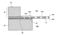
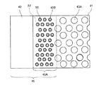
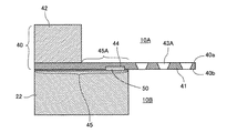
次に、本発明の第1実施形態について図4及び図5を参照して説明する。図4は同実施形態の説明に供するフィルタ部材回りの要部断面説明図、図5は同じくフィルタ部材上流側から見た平面説明図である。 Next, a first embodiment of the present invention will be described with reference to FIGS. FIG. 4 is a cross-sectional explanatory view of a main part around the filter member for explaining the embodiment, and FIG. 5 is a plan explanatory view as seen from the upstream side of the filter member.
フィルタ部材40は、多数の孔43A、43Bが形成された薄肉層41と、薄肉層41の周縁部分に設けられた厚肉層42とを有している。フィルタ部材40を薄肉層41と厚肉層42とで構成することにより、小さな開口(孔43)で、圧力損失を大きくすることなく、フィルタ部材40の組立て時のハンドリング性が向上する。
The
ここで、孔43A、孔43Bは、上流側の開口面積(液体の流れ方向と直交する方向の断面積)が下流側の開口面積よりも大きい断面テーパ形状に形成されている。また、孔43Aは液体が流れるフィルタ孔として機能する対し、孔43Bは後述するように液体は流れず、フィルタ孔としては機能せず、接着剤溜まり部となる。
Here, the holes 43 </ b> A and 43 </ b> B are formed in a tapered cross section in which the upstream opening area (cross-sectional area in the direction orthogonal to the liquid flow direction) is larger than the downstream opening area. The
そして、フィルタ部材40の厚肉層42は第1共通液室部材21に接着剤で接合されている。また、フィルタ部材40の薄肉層41は、厚肉層42を設けた面(この面を「上流側フィルタ面40a」という。)と反対側の面(この面を「下流側フィルタ面40b」という。)の周縁部分45が、第2共通液室部材22に接合されている。
The
ここで、フィルタ部材40の薄肉層41に設けられた孔43A、43Bのうち、第2共通液室部材22と接合された周縁部分45のうちの薄肉層41のみで形成されている領域(これを「薄肉部」という。)45Aに設けられた孔43Bは、厚肉層42側が露出している。
Here, of the
つまり、液体の流れ方向と直交する方向で、フィルタ部材40の厚肉層42の内周壁面は第2共通液室部材22の内周壁面よりも外側に位置するように形成している。言い換えれば、厚肉層42の液体の流れ方向と直交する方向の断面積(開口面積)を、第2共通液室部材22の液体の流れ方向と直交する方向の断面積(開口面積)よりも大きくしている。
That is, the inner peripheral wall surface of the
なお、本実施形態では、薄肉層41の周縁部分45のうちの厚肉層42が設けられていない薄肉部45Aにのみ孔43Bを形成しているが、厚肉層42が設けられている領域を含めて孔43Bを形成することもできる。
In the present embodiment, the
このように構成したので、まず、フィルタ部材40と第2共通液室部材22とを接着剤接合するとき、接着剤50が孔43B内にはみ出した状態になる。孔43B内に接着剤50がはみ出すことで、薄肉層41と第2共通液室部材22の接着面積(接合面積)を大きく確保することができ、また、孔43B内の接着剤50がアンカーとして機能することで、接着強度(接合強度)を大きくすることができる。
Since it comprised in this way, when joining the
また、液体の流れ方向と直交する方向で、フィルタ部材40の厚肉層42の内周壁面は第2共通液室部材22の内周壁面よりも外側に位置して、フィルタ部材40の薄肉部45Aに設けられた孔43aは厚肉層42側が露出していることで、孔43B内にはみ出した接着剤50が更にフィルタ領域まではみ出すことが防止されるので、フィルタ領域の流れを阻害することがなくなる。
Further, in the direction orthogonal to the liquid flow direction, the inner peripheral wall surface of the
さらに、液体の流れ方向と直交する方向で、フィルタ部材40の厚肉層42の内周壁面は第2共通液室部材22の内周壁面よりも外側に位置して、フィルタ部材40の薄肉部45Aに設けられた孔43aは厚肉層42側が露出していることで、フィルタ部材40の下流側での気泡の滞留を低減できて、気泡排出性を向上できる。
Further, the inner peripheral wall surface of the
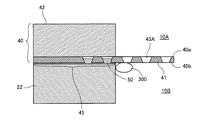
つまり、図6に示すように、下流側共通液室10Bの内周壁面に気泡300が付着した場合、気泡300は内周壁面に沿って浮力によってフィルタ部材40の孔43を通過しようとする。ここで、厚肉層42の液体の流れ方向と直交する方向の断面積(開口面積)が第2共通液室部材22の液体の流れ方向と直交する方向の断面積(開口面積)よりも大きいので、気泡300が上流側共通液室10A側に移動するとき、気泡300の移動を遮るものがなく、気泡300は上流側共通液室10Aに移動し易くなり、気泡排出性が向上する。
That is, as shown in FIG. 6, when the
ここで、本実施形態の上記作用効果を明確にするため、比較例1ないし3について図7ないし図9を参照して説明する。各図は同比較例1、2の説明に供するフィルタ部材周りの要部断面説明図である。 Here, Comparative Examples 1 to 3 will be described with reference to FIGS. 7 to 9 in order to clarify the operational effects of the present embodiment. Each figure is a cross-sectional explanatory view of a main part around a filter member used for explaining the first and second comparative examples.
図7に示す比較例1は、上記実施形態において、薄肉層41の周縁部分45には厚肉層42が設けられていない薄肉部45Aを含めて孔43Bを形成しない構成としたものである。
The comparative example 1 shown in FIG. 7 has a configuration in which the
この比較例1にあっては、図7(a)に示すように、フィルタ部材40を第2共通液室部材22に接着剤50で接合する場合、フィルタ部材40の厚肉層42を加圧して接着するが、薄肉部45Aは加圧力が直接作用しない不加圧領域となる。さらに、薄肉層41の厚さは非常に薄いために変形し易い。その結果、図7(b)に示すように、薄肉層41の薄肉部45Aで、浮きや撓みによって接合不良箇所301が発生し易くなる。
In this comparative example 1, as shown in FIG. 7A, when the
図8に示す比較例2は、フィルタ部材40の厚肉層42の液体の流れ方向と直交する方向の断面積(開口面積)が第2共通液室部材22の液体の流れ方向と直交する方向の断面積(開口面積)よりも小さい構成としたものである。
In Comparative Example 2 shown in FIG. 8, the cross-sectional area (opening area) in the direction orthogonal to the liquid flow direction of the
この比較例2にあっては、下流側共通液室10Bの内周壁面に付着した気泡300が内周壁面に沿って上流側共通液室10A側に移動するとき、厚肉層42によって遮られるので、気泡300が上流側共通液室10Aに移動し難くなり、第2共通液室部材22の内周壁面に気泡300が溜まり易くなる。
In Comparative Example 2, when the
図9に示す比較例3は、フィルタ部材40の厚肉層42の液体の流れ方向と直交する方向の断面積(開口面積)が第2共通液室部材22の液体の流れ方向と直交する方向の断面積(開口面積)と同じである構成としたものである。
In Comparative Example 3 shown in FIG. 9, the cross-sectional area (opening area) in the direction orthogonal to the liquid flow direction of the
この比較例3にあっては、厚肉層42と第2共通液室部材22の開口面積が寸法精度上も同じで、かつ、接合時の位置ずれもなく接合できるのであれば、気泡300が溜まることはないが、現実的には、部品寸法のばらつきや接合精度のばらつきを避けることはできず、比較例2と同様な状態になり、気泡溜まりが生じる。
In Comparative Example 3, if the opening area of the
また、比較例1にあっては、接着剤50の逃げ場がないことで、接着剤50がフィルタ領域側に溢れ出すおそれがある。同様に、比較例2、3にあっても、孔43Bが厚肉部42で覆われているため、孔43Bで吸収できなかったときには、接着剤50がフィルタ領域側に溢れ出すおそれがある。
Further, in Comparative Example 1, the adhesive 50 may overflow to the filter region side because there is no escape place of the adhesive 50. Similarly, in Comparative Examples 2 and 3, since the
これに対し、本実施形態では、上述したように、接合強度の確保と、フィルタ領域へのあふれ出しの防止及び気泡排出性の向上とを図ることができる。 On the other hand, in the present embodiment, as described above, it is possible to secure the bonding strength, prevent the overflow to the filter region, and improve the bubble discharge property.
次に、本発明の第2実施形態について図10を参照して説明する。図10は同実施形態の説明に供するフィルタ部材周りの要部断面説明図である。 Next, a second embodiment of the present invention will be described with reference to FIG. FIG. 10 is a cross-sectional explanatory view of a main part around the filter member for explaining the embodiment.
本実施形態では、フィルタ部材40の薄肉部45Aに形成された孔43Bの開口から接着剤50が溢れ出ている構成としている。
In the present embodiment, the adhesive 50 overflows from the opening of the
これにより、孔43Bの開口から溢れ出た接着剤50がリベット形状となり、接着剤50の化学的な接着力以外に、構造的に接着力を向上させることができ、より接着強度の向上を図れる。
Thereby, the adhesive 50 overflowing from the opening of the
なお、接着剤を溢れ出せるには、接着剤の量を多くする、接着時の加圧力を高くするなどの手段を用いることができる。 In order to overflow the adhesive, it is possible to use means such as increasing the amount of the adhesive or increasing the pressure applied during bonding.
次に、本発明の第3実施形態について図11を参照して説明する。図11は同実施形態の説明に供するフィルタ部材周りの要部断面説明図である。 Next, a third embodiment of the present invention will be described with reference to FIG. FIG. 11 is a cross-sectional explanatory view of a main part around the filter member for explaining the embodiment.
本実施形態では、フィルタ部材40の薄肉部45Aに形成された孔43Bの開口から接着剤50が溢れ出し、孔43Bの周囲に覆い被さるように構成している。つまり、溢れ出した接着剤50の投影面積が、孔43Bの上流側フィルタ面40a側の開口面積よりも部分的に広くなっていれば良い。
In the present embodiment, the adhesive 50 overflows from the opening of the
これにより、上記第2実施形態よりも更に接着強度の向上を図れる。 Thereby, the adhesive strength can be further improved as compared with the second embodiment.
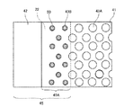
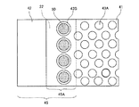
次に、本発明の第4実施形態について図12及び図13を参照して説明する。図12は同実施形態の説明に供するフィルタ部材回りの要部断面説明図、図13は同じくフィルタ部材上流側から見た平面説明図である。 Next, a fourth embodiment of the present invention will be described with reference to FIGS. FIG. 12 is a cross-sectional explanatory view of a main part around the filter member for explaining the embodiment, and FIG. 13 is a plan explanatory view as seen from the upstream side of the filter member.
本実施形態では、フィルタ部材40の薄肉層41に形成する孔43のうち、フィルタ孔として機能する孔43Aよりも薄肉部45Aに形成する孔43Bの液体の流れ方向における開口断面積(平均値)を小さく形成している。この場合、単位面積当たりの孔43Aの数と孔43Bの数は同じにしている。
In the present embodiment, among the holes 43 formed in the
このように、薄肉部45Aの孔43Bの開口断面積を小さくすることによって、毛細現象によって接着剤50が孔43B内に這い上がり易くなるために、アンカー効果が得られ易くなる。更には、這い上がった接着剤50が上流側フィルタ面40aに回り込み、リベット効果によって更に強度を確保することができる。
In this way, by reducing the opening cross-sectional area of the
次に、本発明の第5実施形態について図14及び図15を参照して説明する。図14は同実施形態の説明に供するフィルタ部材回りの要部断面説明図、図15は同じくフィルタ部材上流側から見た平面説明図である。 Next, a fifth embodiment of the present invention will be described with reference to FIGS. FIG. 14 is a cross-sectional explanatory view of a main part around the filter member for explaining the embodiment, and FIG. 15 is a plan explanatory view as seen from the upstream side of the filter member.
本実施形態では、前記第4実施形態において、単位面積当たりの孔43Aの数よりも孔43Bの数を多くしている。
In the present embodiment, in the fourth embodiment, the number of
これにより、前記第4実施形態よりも、接着強度を高くすることができる。 Thereby, adhesive strength can be made higher than the said 4th Embodiment.
なお、接着強度を確保できるのであれば、単位面積当たりの孔43Aの数よりも孔43Bの数を少なくすることもできる。
If the adhesive strength can be ensured, the number of
次に、本発明の第6実施形態について図16及び図17を参照して説明する。図16は同実施形態の説明に供するフィルタ部材回りの要部断面説明図、図17は同じくフィルタ部材上流側から見た平面説明図である。 Next, a sixth embodiment of the present invention will be described with reference to FIGS. FIG. 16 is a cross-sectional explanatory view of a main part around the filter member for explaining the embodiment, and FIG. 17 is a plan explanatory view as seen from the upstream side of the filter member.
本実施形態では、フィルタ部材40の薄肉層41に形成する孔43のうち、フィルタ孔として機能する孔43Aよりも薄肉部45Aに形成する孔43Bの液体の流れ方向における開口断面積(平均値)を大きく形成している。
In the present embodiment, among the holes 43 formed in the
つまり、接着不良を低減させるためには、接着剤の量をできるだけ多くして塗布することが好ましい。しかしながら、接着剤の量が多い場合、加圧時に流れ出す量が多くなるため、フィルタ面積(フィルタ孔となる孔43Aが設けられた領域の面積)を減少させてしまうおそれがある。
That is, in order to reduce adhesion failure, it is preferable to apply with the amount of adhesive as large as possible. However, when the amount of the adhesive is large, the amount that flows out during pressurization increases, and therefore there is a possibility that the filter area (area of the region provided with the
そこで、接着剤50を逃がす孔43Bの開口面積を大きくすることで、接着剤50の溜まり部を広く確保することができるため、接着剤の過度の流れ出しを防止することができる。
Therefore, by increasing the opening area of the
次に、本発明の第7実施形態の異なる例について図18及び図19を参照して説明する。各図は同実施形態の説明に供するフィルタ部材回りの要部断面説明図である。 Next, a different example of the seventh embodiment of the present invention will be described with reference to FIGS. Each drawing is a cross-sectional explanatory view of a main part around a filter member for explaining the embodiment.
本実施形態では、前記第6実施形態の孔43Bを円形状としていたのに対し、長孔形状としている。この場合、孔43Bの配置は、図18及び図19のいずれでもよい。
In the present embodiment, the
次に、本発明の第8実施形態の異なる例について図20及び図21を参照して説明する。各図は同実施形態の説明に供するフィルタ部材回りの要部断面説明図である。 Next, a different example of the eighth embodiment of the present invention will be described with reference to FIGS. Each drawing is a cross-sectional explanatory view of a main part around a filter member for explaining the embodiment.
本実施形態では、フィルタ部材40の第2共通液室部材22との接合領域となる薄肉部45Aに、第2共通液室部材22側に開口した凹部44を形成している。凹部44は、図20に示すように矩形状でもよいし、図21に示すようにかまぼこ形状であってもよい。
In the present embodiment, a recessed
このように、凹部44を形成しても、接着剤50が凹部44内に入り込むので、アンカー効果が得られ、仮に接着面積が小さくなった場合においても接着強度を確保することができる。
Thus, even if the
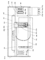
次に、本発明に係る液体吐出ヘッドを備える本発明に係る画像形成装置の一例について図22及び図23を参照して説明する。なお、図22は同装置の機構部の側面説明図、図23は同機構部の要部平面説明図である。 Next, an example of the image forming apparatus according to the present invention including the liquid ejection head according to the present invention will be described with reference to FIGS. FIG. 22 is an explanatory side view of the mechanism portion of the apparatus, and FIG. 23 is an explanatory plan view of the main portion of the mechanism portion.
この画像形成装置はシリアル型画像形成装置であり、左右の側板221A、221Bに横架したガイド部材である主従のガイドロッド231、232でキャリッジ233を主走査方向に摺動自在に保持し、図示しない主走査モータによってタイミングベルトを介して矢示方向(キャリッジ主走査方向)に移動走査する。
This image forming apparatus is a serial type image forming apparatus, and a
このキャリッジ233には、イエロー(Y)、シアン(C)、マゼンタ(M)、ブラック(K)の各色のインク滴を吐出するための本発明に係る液体吐出ヘッドと同ヘッドに供給するインクを収容するタンクを一体化した記録ヘッド234を複数のノズルからなるノズル列を主走査方向と直交する副走査方向に配列し、インク滴吐出方向を下方に向けて装着している。
The
記録ヘッド234は、それぞれ2つのノズル列を有し、一方の記録ヘッド234aの一方のノズル列はブラック(K)の液滴を、他方のノズル列はシアン(C)の液滴を、他方の記録ヘッド234bの一方のノズル列はマゼンタ(M)の液滴を、他方のノズル列はイエロー(Y)の液滴を、それぞれ吐出する。なお、ここでは2ヘッド構成で4色の液滴を吐出する構成としているが、1ヘッド当たり4ノズル列配置とし、1個のヘッドで4色の各色を吐出させることもできる。
Each of the recording heads 234 has two nozzle rows, and one nozzle row of one
また、記録ヘッド234のタンク235には各色の供給チューブ236を介して、供給ユニット224によって各色のインクカートリッジ210から各色のインクが補充供給される。
Further, the ink of each color is replenished and supplied from the ink cartridge 210 of each color to the
一方、給紙トレイ202の用紙積載部(圧板)241上に積載した用紙242を給紙するための給紙部として、用紙積載部241から用紙242を1枚ずつ分離給送する半月コロ(給紙コロ)243及び給紙コロ243に対向し、摩擦係数の大きな材質からなる分離パッド244を備え、この分離パッド244は給紙コロ243側に付勢されている。
On the other hand, as a paper feeding unit for feeding the
そして、この給紙部から給紙された用紙242を記録ヘッド234の下方側に送り込むために、用紙242を案内するガイド245と、カウンタローラ246と、搬送ガイド部材247と、先端加圧コロ249を有する押さえ部材248とを備えるとともに、給送された用紙242を静電吸着して記録ヘッド234に対向する位置で搬送するための搬送手段である搬送ベルト251を備えている。
A
この搬送ベルト251は、無端状ベルトであり、搬送ローラ252とテンションローラ253との間に掛け渡されて、ベルト搬送方向(副走査方向)に周回するように構成している。また、この搬送ベルト251の表面を帯電させるための帯電手段である帯電ローラ256を備えている。この帯電ローラ256は、搬送ベルト251の表層に接触し、搬送ベルト251の回動に従動して回転するように配置されている。この搬送ベルト251は、図示しない副走査モータによってタイミングを介して搬送ローラ252が回転駆動されることによってベルト搬送方向に周回移動する。
The
さらに、記録ヘッド234で記録された用紙242を排紙するための排紙部として、搬送ベルト251から用紙242を分離するための分離爪261と、排紙ローラ262及び排紙コロ263とを備え、排紙ローラ262の下方に排紙トレイ203を備えている。
Further, as a paper discharge unit for discharging the
また、装置本体の背面部には両面ユニット271が着脱自在に装着されている。この両面ユニット271は搬送ベルト251の逆方向回転で戻される用紙242を取り込んで反転させて再度カウンタローラ246と搬送ベルト251との間に給紙する。また、この両面ユニット271の上面は手差しトレイ272としている。
A double-
さらに、キャリッジ233の走査方向一方側の非印字領域には、記録ヘッド234のノズルの状態を維持し、回復するための回復手段を含む本発明に係るヘッドの維持回復装置である維持回復機構281を配置している。この維持回復機構281には、記録ヘッド234の各ノズル面をキャピングするための各キャップ部材(以下「キャップ」という。)282a、282b(区別しないときは「キャップ282」という。)と、ノズル面をワイピングするためのブレード部材であるワイパーブレード283と、増粘した記録液を排出するために記録に寄与しない液滴を吐出させる空吐出を行うときの液滴を受ける空吐出受け284などを備えている。
Further, a maintenance /
また、キャリッジ233の走査方向他方側の非印字領域には、記録中などに増粘した記録液を排出するために記録に寄与しない液滴を吐出させる空吐出を行うときの液滴を受ける空吐出受け288を配置し、この空吐出受け288には記録ヘッド234のノズル列方向に沿った開口部289などを備えている。
Further, in the non-printing area on the other side in the scanning direction of the
このように構成したこの画像形成装置においては、給紙トレイ202から用紙242が1枚ずつ分離給紙され、略鉛直上方に給紙された用紙242はガイド245で案内され、搬送ベルト251とカウンタローラ246との間に挟まれて搬送され、更に先端を搬送ガイド237で案内されて先端加圧コロ249で搬送ベルト251に押し付けられ、略90°搬送方向を転換される。
In this image forming apparatus configured as described above, the
このとき、帯電ローラ256に対してプラス出力とマイナス出力とが交互に繰り返すように、つまり交番する電圧が印加され、搬送ベルト251が交番する帯電電圧パターン、すなわち、周回方向である副走査方向に、プラスとマイナスが所定の幅で帯状に交互に帯電されたものとなる。このプラス、マイナス交互に帯電した搬送ベルト251上に用紙242が給送されると、用紙242が搬送ベルト251に吸着され、搬送ベルト251の周回移動によって用紙242が副走査方向に搬送される。
At this time, a positive output and a negative output are alternately applied to the charging
そこで、キャリッジ233を移動させながら画像信号に応じて記録ヘッド234を駆動することにより、停止している用紙242にインク滴を吐出して1行分を記録し、用紙242を所定量搬送後、次の行の記録を行う。記録終了信号又は用紙242の後端が記録領域に到達した信号を受けることにより、記録動作を終了して、用紙242を排紙トレイ203に排紙する。
Therefore, by driving the
このように、この画像形成装置では、本発明に係る液体吐出ヘッドを記録ヘッドとして備えるので、高画質画像を安定して形成することができる。 As described above, since the image forming apparatus includes the liquid discharge head according to the present invention as a recording head, a high-quality image can be stably formed.
なお、本願において、「用紙」とは材質を紙に限定するものではなく、OHP、布、ガラス、基板などを含み、インク滴、その他の液体などが付着可能なものの意味であり、被記録媒体、記録媒体、記録紙、記録用紙などと称されるものを含む。また、画像形成、記録、印字、印写、印刷はいずれも同義語とする。 In the present application, the “paper” is not limited to paper, but includes OHP, cloth, glass, a substrate, etc., and means a material to which ink droplets or other liquids can be attached. , Recording media, recording paper, recording paper, and the like. In addition, image formation, recording, printing, printing, and printing are all synonymous.
また、「画像形成装置」は、紙、糸、繊維、布帛、皮革、金属、プラスチック、ガラス、木材、セラミックス等の媒体に液体を吐出して画像形成を行う装置を意味し、また、「画像形成」とは、文字や図形等の意味を持つ画像を媒体に対して付与することだけでなく、パターン等の意味を持たない画像を媒体に付与すること(単に液滴を媒体に着弾させること)をも意味する。 The “image forming apparatus” means an apparatus that forms an image by discharging liquid onto a medium such as paper, thread, fiber, fabric, leather, metal, plastic, glass, wood, ceramics, etc. “Formation” means not only giving an image having a meaning such as a character or a figure to a medium but also giving an image having no meaning such as a pattern to the medium (simply causing a droplet to land on the medium). ) Also means.
また、「インク」とは、特に限定しない限り、インクと称されるものに限らず、記録液、定着処理液、液体などと称されるものなど、画像形成を行うことができるすべての液体の総称として用い、例えば、DNA試料、レジスト、パターン材料、樹脂なども含まれる。 The “ink” is not limited to an ink unless otherwise specified, but includes any liquid that can form an image, such as a recording liquid, a fixing processing liquid, or a liquid. Used generically, for example, includes DNA samples, resists, pattern materials, resins, and the like.
また、「画像」とは平面的なものに限らず、立体的に形成されたものに付与された画像、また立体自体を三次元的に造形して形成された像も含まれる。 In addition, the “image” is not limited to a planar image, and includes an image given to a three-dimensionally formed image and an image formed by three-dimensionally modeling a solid itself.
また、画像形成装置には、特に限定しない限り、シリアル型画像形成装置及びライン型画像形成装置のいずれも含まれる。 Further, the image forming apparatus includes both a serial type image forming apparatus and a line type image forming apparatus, unless otherwise limited.
1 ノズル板
2 流路板
3 振動板部材
4 ノズル
6 個別液室(個別流路、圧力室)
8 液導入部
10 共通液室
10A 上流側共通液室
10B 下流側共通液室
12 圧電部材
20 共通液室部材
21 第1共通液室部材
22 第2共通液室部材
40 フィルタ部材
41 薄肉層
42 厚肉層
43A 孔(フィルタ孔)
43B 孔
44 凹部
45 周囲部分
45A 薄肉部
50 接着剤
233 キャリッジ
234a、234b 記録ヘッド
1
8
Claims (6)
前記ノズルが通じる複数の個別液室と、
前記複数の個別液室に液体を供給する共通液室と、
前記共通液室内で前記液体をろ過するフィルタ部材と、を備え、
前記共通液室を構成する部材は、前記フィルタ部材上流側の第1共通液室部材と、前記フィルタ部材下流側の第2共通液室部材とを、有し、
前記フィルタ部材は、複数の孔が形成された薄肉層と、前記薄肉層の周縁部に設けられた厚肉層と、を有し、
前記フィルタ部材の厚肉層は、前記第1共通液室部材に接合され、
前記フィルタ部材の薄肉層の前記厚肉層を設けた面と反対側の面の周縁部分は、前記第2共通液室部材と接着剤により接合され、
前記フィルタ部材の薄肉層の前記複数の孔のうち、前記第2共通液室部材と接合された周縁部分に設けられた孔の一部又は全部は、前記厚肉層側が露出し、
前記周縁部分に設けられた孔の一部又は全部に、前記接着剤がはみ出している
ことを特徴とする液体吐出ヘッド。 A plurality of nozzles for discharging droplets;
A plurality of individual liquid chambers through which the nozzle communicates;
A common liquid chamber for supplying a liquid to the plurality of individual liquid chambers;
A filter member for filtering the liquid in the common liquid chamber,
The member constituting the common liquid chamber has a first common liquid chamber member on the upstream side of the filter member, and a second common liquid chamber member on the downstream side of the filter member,
The filter member has a thin layer in which a plurality of holes are formed, and a thick layer provided on a peripheral portion of the thin layer,
The thick layer of the filter member is joined to the first common liquid chamber member,
The peripheral portion of the surface opposite to the surface on which the thick layer of the thin layer of the filter member is provided is bonded to the second common liquid chamber member with an adhesive,
Among the plurality of holes of the thin layer of the filter member, part or all of the holes provided in the peripheral portion joined to the second common liquid chamber member are exposed on the thick layer side,
The liquid discharge head, wherein the adhesive protrudes from a part or all of the holes provided in the peripheral portion.
前記ノズルが通じる複数の個別液室と、
前記複数の個別液室に液体を供給する共通液室と、
前記共通液室内で前記液体をろ過するフィルタ部材と、を備え、
前記共通液室を構成する部材は、前記フィルタ部材上流側の第1共通液室部材と、前記フィルタ部材下流側の第2共通液室部材とを、有し、
前記フィルタ部材は、複数の孔が形成された薄肉層と、前記薄肉層の周縁部に設けられた厚肉層と、を有し、
前記フィルタ部材の厚肉層は、前記第1共通液室部材に接合され、
前記フィルタ部材の薄肉層の前記厚肉層を設けた面と反対側の面の周縁部分は、前記第2共通液室部材に接合され、
前記フィルタ部材の薄肉層の周縁部分には、前記第2共通液室部材側に開口する凹部が形成され、
前記フィルタ部材の前記凹部が形成された周縁部分の一部又は全部は、前記厚肉層側が露出している
ことを特徴とする液体吐出ヘッド。 A plurality of nozzles for discharging droplets;
A plurality of individual liquid chambers through which the nozzle communicates;
A common liquid chamber for supplying a liquid to the plurality of individual liquid chambers;
A filter member for filtering the liquid in the common liquid chamber,
The member constituting the common liquid chamber has a first common liquid chamber member on the upstream side of the filter member, and a second common liquid chamber member on the downstream side of the filter member,
The filter member has a thin layer in which a plurality of holes are formed, and a thick layer provided on a peripheral portion of the thin layer,
The thick layer of the filter member is joined to the first common liquid chamber member,
The peripheral portion of the surface opposite to the surface on which the thick layer of the thin layer of the filter member is provided is joined to the second common liquid chamber member,
In the peripheral portion of the thin layer of the filter member is formed a recess that opens to the second common liquid chamber member side,
The liquid discharge head according to claim 1, wherein the thick layer side is exposed at a part or all of a peripheral portion of the filter member where the concave portion is formed.
Priority Applications (2)
| Application Number | Priority Date | Filing Date | Title |
|---|---|---|---|
| JP2012055525A JP5954565B2 (en) | 2012-03-13 | 2012-03-13 | Liquid ejection head and image forming apparatus |
| US13/778,271 US8888260B2 (en) | 2012-03-13 | 2013-02-27 | Liquid-jet head and image forming apparatus |
Applications Claiming Priority (1)
| Application Number | Priority Date | Filing Date | Title |
|---|---|---|---|
| JP2012055525A JP5954565B2 (en) | 2012-03-13 | 2012-03-13 | Liquid ejection head and image forming apparatus |
Publications (2)
| Publication Number | Publication Date |
|---|---|
| JP2013188907A JP2013188907A (en) | 2013-09-26 |
| JP5954565B2 true JP5954565B2 (en) | 2016-07-20 |
Family
ID=49157212
Family Applications (1)
| Application Number | Title | Priority Date | Filing Date |
|---|---|---|---|
| JP2012055525A Active JP5954565B2 (en) | 2012-03-13 | 2012-03-13 | Liquid ejection head and image forming apparatus |
Country Status (2)
| Country | Link |
|---|---|
| US (1) | US8888260B2 (en) |
| JP (1) | JP5954565B2 (en) |
Families Citing this family (12)
| Publication number | Priority date | Publication date | Assignee | Title |
|---|---|---|---|---|
| JP6119276B2 (en) * | 2013-02-06 | 2017-04-26 | 株式会社リコー | Liquid ejection head and image forming apparatus |
| JP6347159B2 (en) | 2013-09-13 | 2018-06-27 | 株式会社リコー | Liquid ejection head and image forming apparatus |
| JP6165574B2 (en) * | 2013-09-26 | 2017-07-19 | シスメックス株式会社 | Filter member and cell acquisition method |
| JP2016060101A (en) | 2014-09-18 | 2016-04-25 | 株式会社リコー | Liquid discharge head and image forming apparatus |
| CN107249891B (en) * | 2015-02-18 | 2019-03-12 | 京瓷株式会社 | Channel member, fluid ejection head and recording device using the channel member |
| JP6531423B2 (en) * | 2015-02-24 | 2019-06-19 | セイコーエプソン株式会社 | Printing device |
| US9815284B2 (en) * | 2015-04-07 | 2017-11-14 | Ricoh Company, Ltd. | Liquid discharge head, liquid discharge device, and liquid discharge apparatus |
| JP6658353B2 (en) * | 2015-09-30 | 2020-03-04 | 株式会社リコー | Liquid discharge head, liquid discharge unit, device for discharging liquid |
| JP6769022B2 (en) | 2015-10-07 | 2020-10-14 | 株式会社リコー | Liquid discharge head, liquid discharge unit, device that discharges liquid |
| US10022963B2 (en) | 2015-11-06 | 2018-07-17 | Ricoh Company, Ltd. | Liquid discharge head, liquid discharge device, and liquid discharge apparatus |
| WO2021008700A1 (en) * | 2019-07-17 | 2021-01-21 | Scrona Ag | Inkjet print head with contamination robustness |
| JP2022130973A (en) * | 2021-02-26 | 2022-09-07 | ブラザー工業株式会社 | Liquid discharge head |
Family Cites Families (17)
| Publication number | Priority date | Publication date | Assignee | Title |
|---|---|---|---|---|
| JPH0966607A (en) | 1995-08-30 | 1997-03-11 | Brother Ind Ltd | Ink jet head and ink jet recorder |
| JPH10315484A (en) * | 1997-05-22 | 1998-12-02 | Fuji Electric Co Ltd | Ink jet recorder and manufacture thereof |
| US6139674A (en) * | 1997-09-10 | 2000-10-31 | Xerox Corporation | Method of making an ink jet printhead filter by laser ablation |
| US6086195A (en) * | 1998-09-24 | 2000-07-11 | Hewlett-Packard Company | Filter for an inkjet printhead |
| JP4314981B2 (en) * | 2003-12-01 | 2009-08-19 | ブラザー工業株式会社 | Inkjet head |
| JP4186884B2 (en) * | 2004-06-30 | 2008-11-26 | ブラザー工業株式会社 | Inkjet printer head |
| JP2006289643A (en) | 2005-04-06 | 2006-10-26 | Brother Ind Ltd | Image recorder |
| JP4665747B2 (en) * | 2005-12-16 | 2011-04-06 | ブラザー工業株式会社 | Plate stack structure and liquid discharge head |
| JP5168934B2 (en) | 2006-05-26 | 2013-03-27 | 株式会社リコー | Liquid ejection head, liquid ejection apparatus, image forming apparatus, piezoelectric actuator |
| US7651205B2 (en) | 2006-12-01 | 2010-01-26 | Ricoh Company, Ltd. | Liquid discharging head using piezoelectric actuator and image forming apparatus using the liquid discharging head |
| JP4869108B2 (en) | 2007-03-01 | 2012-02-08 | 株式会社リコー | Liquid ejection head, liquid cartridge, and image forming apparatus |
| JP4944687B2 (en) | 2007-06-28 | 2012-06-06 | 株式会社リコー | Piezoelectric actuator and manufacturing method thereof, liquid ejection head, and image forming apparatus |
| JP2010105251A (en) | 2008-10-29 | 2010-05-13 | Brother Ind Ltd | Liquid delivering head and method for manufacturing the same |
| JP5677702B2 (en) | 2009-06-29 | 2015-02-25 | 株式会社リコー | Liquid discharge head unit and image forming apparatus |
| JP5375669B2 (en) * | 2009-06-29 | 2013-12-25 | 株式会社リコー | Liquid ejection head, liquid droplet ejection apparatus, and image forming apparatus |
| JP5633200B2 (en) | 2010-06-08 | 2014-12-03 | 株式会社リコー | Piezoelectric actuator, liquid discharge head, and image forming apparatus |
| US8926068B2 (en) | 2011-01-14 | 2015-01-06 | Ricoh Company, Ltd. | Liquid discharge head, method of manufacturing liquid discharge head, and image forming device |
-
2012
- 2012-03-13 JP JP2012055525A patent/JP5954565B2/en active Active
-
2013
- 2013-02-27 US US13/778,271 patent/US8888260B2/en not_active Expired - Fee Related
Also Published As
| Publication number | Publication date |
|---|---|
| US20130242012A1 (en) | 2013-09-19 |
| US8888260B2 (en) | 2014-11-18 |
| JP2013188907A (en) | 2013-09-26 |
Similar Documents
| Publication | Publication Date | Title |
|---|---|---|
| JP5954565B2 (en) | Liquid ejection head and image forming apparatus | |
| JP5754188B2 (en) | Liquid ejection head and image forming apparatus | |
| JP6011015B2 (en) | Liquid ejection head and image forming apparatus | |
| JP6256107B2 (en) | Liquid ejection head and image forming apparatus | |
| JP5633200B2 (en) | Piezoelectric actuator, liquid discharge head, and image forming apparatus | |
| JP6070250B2 (en) | Liquid ejection head and image forming apparatus | |
| JP6119276B2 (en) | Liquid ejection head and image forming apparatus | |
| JP2013063551A (en) | Liquid ejection head, and image forming apparatus | |
| JP6205866B2 (en) | Liquid ejection head and image forming apparatus | |
| JP6083265B2 (en) | Liquid ejection head and image forming apparatus | |
| JP5500017B2 (en) | Liquid ejection head and image forming apparatus | |
| JP6152727B2 (en) | Liquid ejection head and image forming apparatus | |
| JP5943292B2 (en) | Liquid ejection head, image forming apparatus, and liquid ejection head manufacturing method | |
| JP5954567B2 (en) | Liquid ejection head and image forming apparatus | |
| JP6119320B2 (en) | Liquid ejection head and image forming apparatus | |
| JP2013063535A (en) | Liquid ejection head and image forming apparatus | |
| JP5935597B2 (en) | Liquid ejection head and image forming apparatus | |
| JP2015020424A (en) | Liquid discharge head and image formation device | |
| JP2015168189A (en) | Liquid discharge head and image forming apparatus | |
| JP5970883B2 (en) | Liquid ejection head and image forming apparatus | |
| JP5857559B2 (en) | Liquid ejection head and image forming apparatus | |
| JP5957985B2 (en) | Liquid ejection head and image forming apparatus | |
| JP6364724B2 (en) | Liquid ejection head and image forming apparatus | |
| JP2015054445A (en) | Liquid discharge head and image formation apparatus | |
| JP5310414B2 (en) | Liquid ejection head and image forming apparatus |
Legal Events
| Date | Code | Title | Description |
|---|---|---|---|
| A621 | Written request for application examination |
Free format text: JAPANESE INTERMEDIATE CODE: A621 Effective date: 20150217 |
|
| A977 | Report on retrieval |
Free format text: JAPANESE INTERMEDIATE CODE: A971007 Effective date: 20151116 |
|
| A131 | Notification of reasons for refusal |
Free format text: JAPANESE INTERMEDIATE CODE: A131 Effective date: 20151124 |
|
| A521 | Request for written amendment filed |
Free format text: JAPANESE INTERMEDIATE CODE: A523 Effective date: 20151215 |
|
| TRDD | Decision of grant or rejection written | ||
| A01 | Written decision to grant a patent or to grant a registration (utility model) |
Free format text: JAPANESE INTERMEDIATE CODE: A01 Effective date: 20160519 |
|
| A61 | First payment of annual fees (during grant procedure) |
Free format text: JAPANESE INTERMEDIATE CODE: A61 Effective date: 20160601 |
|
| R151 | Written notification of patent or utility model registration |
Ref document number: 5954565 Country of ref document: JP Free format text: JAPANESE INTERMEDIATE CODE: R151 |