JP5954560B2 - Seat belt buckle housing structure - Google Patents
Seat belt buckle housing structure Download PDFInfo
- Publication number
- JP5954560B2 JP5954560B2 JP2011268041A JP2011268041A JP5954560B2 JP 5954560 B2 JP5954560 B2 JP 5954560B2 JP 2011268041 A JP2011268041 A JP 2011268041A JP 2011268041 A JP2011268041 A JP 2011268041A JP 5954560 B2 JP5954560 B2 JP 5954560B2
- Authority
- JP
- Japan
- Prior art keywords
- buckle
- blocking wall
- seat belt
- skin material
- hole
- Prior art date
- Legal status (The legal status is an assumption and is not a legal conclusion. Google has not performed a legal analysis and makes no representation as to the accuracy of the status listed.)
- Active
Links
Images


Landscapes
- Seats For Vehicles (AREA)
- Automotive Seat Belt Assembly (AREA)
Description
本発明は、
シートクッションにバックル収容孔が形成され、
フロア側の固定部に固定されたシートベルトバックルが前記バックル収容孔に収容されているシートベルトバックルの収容構造に関する。
The present invention
A buckle accommodation hole is formed in the seat cushion,
The present invention relates to a seat belt buckle housing structure in which a seat belt buckle fixed to a floor-side fixing portion is housed in the buckle housing hole.
上記のシートベルトバックルの収容構造において、バックル収容孔の内周面とシートベルトバックルの外周面との間に隙間が形成されていると、コイン等の小物が前記隙間から落下してしまう虞がある。
この問題を解消する技術として、従来、シートベルトバックルを収納する袋状のバックル収納部の外周部を、シートクッションの表皮材に形成した開口の周縁部に縫着する技術があった(特許文献1参照)。
前記袋状のバックル収納部の底部中央には、シートベルトバックルに接続したウェビングを挿通させるウェビング挿通孔が形成されている。
In the seat belt buckle housing structure described above, if a gap is formed between the inner circumferential surface of the buckle housing hole and the outer circumferential surface of the seat belt buckle, there is a risk that small items such as coins may fall from the gap. is there.
As a technique for solving this problem, there has conventionally been a technique for sewing the outer peripheral portion of a bag-shaped buckle storage portion for storing a seat belt buckle to the peripheral portion of the opening formed in the skin material of the seat cushion (Patent Literature). 1).
A webbing insertion hole through which a webbing connected to a seat belt buckle is inserted is formed at the bottom center of the bag-shaped buckle storage unit.
冒頭に記載したシートベルトバックルの収容構造の組み付け工程ではシートクッションより先にフロアにシートベルトバックルを組み付け、シートクッションをフロアに上方から載置するに伴なって、シートベルトバックルをシートクッションのバックル収容孔に下方から挿入させている。 In the assembly process of the seat belt buckle housing structure described at the beginning, the seat belt buckle is assembled on the floor before the seat cushion, and the seat belt buckle is mounted on the floor as the seat cushion is placed on the floor from above. The insertion hole is inserted from below.
ところが、特許文献1に記載の技術では、シートベルトバックルはウェビングを介してフロアと接続しており、シートベルトバックルに自立性がないために、シートクッションをフロアに上方から載置するに伴なって、シートベルトバックルをシートクッションのバックル収容孔に下方から挿入させるという上記の手段を採用することができなかった。
例えば、前記ウェビングに換え、自立性のある金属製のブラケットを介してシートベルトバックルをフロアに連結し、前記袋状のバックル収納部の底部中央にバックル挿通孔を形成する構造が考えられる。
この構造によれば、シートクッションより先にフロアにシートベルトバックルを前記ブラケットを介して組み付けておき、シートクッションをフロアに上方から載置するに伴なって、シートベルトバックルをシートクッションのバックル収容孔に下方から挿入させるとともに、袋状のバックル収納部の底部中央のバックル挿通孔に挿通させることができる。
しかしながら、この構造では、シートベルトバックルの挿入の際に袋状のバックル収納部がシートベルトバックルに突き上げられ、シートクッションのバックル収容孔の上方に突出しやすい。そのために、シートクッションの組み付け後に袋状のバックル収納部をバックル収容孔にシートクッションの上方から押し込まなければならず、作業工数が増えて組み付け作業の作業性が低下する。
However, in the technique described in
For example, instead of the webbing, a structure in which a seat belt buckle is connected to a floor via a self-supporting metal bracket, and a buckle insertion hole is formed in the center of the bottom of the bag-like buckle storage part.
According to this structure, the seat belt buckle is assembled to the floor before the seat cushion via the bracket, and the seat belt buckle is accommodated on the floor as the seat cushion is placed on the floor from above. While being inserted into the hole from below, it can be inserted into the buckle insertion hole at the center of the bottom of the bag-shaped buckle storage part.
However, in this structure, when the seat belt buckle is inserted, the bag-like buckle housing portion is pushed up to the seat belt buckle and easily protrudes above the buckle housing hole of the seat cushion. Therefore, after assembling the seat cushion, the bag-shaped buckle housing portion must be pushed into the buckle housing hole from above the seat cushion, increasing the work man-hours and reducing the workability of the assembling work.
本発明は上記実状に鑑みて成されたもので、その目的は、バックル収容孔からの物品の落下を防止できる構造を、組み付け作業性を低下させることなく製作できるシートベルトバックルの収容構造を提供する点にある。 SUMMARY OF THE INVENTION The present invention has been made in view of the above circumstances, and an object thereof is to provide a seat belt buckle housing structure capable of producing a structure capable of preventing the article from dropping from the buckle housing hole without deteriorating assembly workability. There is in point to do.
本発明の特徴は、
シートクッションにバックル収容孔が形成され、
フロア側の固定部に固定されたシートベルトバックルが前記バックル収容孔に収容されているシートベルトバックルの収容構造であって、
前記バックル収容孔の内側面及び上側開口の周縁部に、前記バックル収容孔への物品の侵入落下を阻止する阻止壁が立設され、
前記シートベルトバックルは前記バックル収容孔内で前記阻止壁に内嵌し、
前記阻止壁の上部の嵌合壁面が前記バックル収容孔内で前記シートベルトバックルの側面に面接触して、前記阻止壁の上部が上下方向に沿うとともに、前記阻止壁の上端部が前記バックル収容孔の上方に突出していて、
前記阻止壁は、芯材と、前記芯材を挟み込んで覆う一対の阻止壁形成部材とを、前記バックル収容孔の内側面の表皮材に縫着して構成される点にある。(請求項1)
The feature of the present invention is that
A buckle accommodation hole is formed in the seat cushion,
A seat belt buckle housing structure in which a seat belt buckle fixed to a fixed portion on the floor side is housed in the buckle housing hole,
On the inner side surface of the buckle housing hole and the peripheral edge of the upper opening, a blocking wall for preventing the entry and dropping of the article into the buckle housing hole is erected,
The seat belt buckle is fitted into the blocking wall in the buckle receiving hole,
The fitting wall surface at the top of the blocking wall is in surface contact with the side surface of the seat belt buckle in the buckle receiving hole, the upper portion of the blocking wall is along the vertical direction, and the upper end of the blocking wall is stored in the buckle. Protruding above the hole ,
The blocking wall is formed by sewing a core material and a pair of blocking wall forming members sandwiching and covering the core material to the skin material on the inner surface of the buckle accommodation hole . (Claim 1)
この構成によれば、シートクッションの座面に落下してバックル収容孔に向かう物品(例えばコイン等の小物)を、バックル収容孔の上側開口の周縁部に立設された阻止壁で受け止めて、物品がバックル収容孔に侵入することを阻止することができる。
そして、組み付け工程においては、シートクッションより先にフロアにシートベルトバックルを組み付けておき、シートクッションをフロアに上方から載置するに伴なって、シートベルトバックルをバックル収容孔に下方から挿入することができる。
この組み付け工程においてシートベルトバックルを袋状のバックル収納部のバックル挿通孔に挿通させる構造では、バックル挿通孔を大きくすると、コイン等の小物がバックル挿通孔を通ってバックル収容孔からシートクッションの下方に落下することから、バックル挿通孔を大きく設定できず、そのために、シートベルトバックルをバックル挿通孔に挿通させにくい不具合がある。
これに対して、本発明の上記構成によれば、袋状のバックル収納部のバックル挿通孔にシートベルトバックルを挿通させることはないから上記の不具合がない。従って、組み付け作業の作業性を向上させることができる。
また、前記シートベルトバックルは前記阻止壁に内嵌しているから、バックル収容孔をシートベルトバックルで塞ぐことができる。その結果、バックル収容孔への物品の侵入落下をシートベルトバックルと阻止壁とで防止することができる。(請求項1)
本発明において、
一方の前記阻止壁形成部材の上端部は他方の前記阻止壁形成部材の上端部側に折り返され、
前記他方の阻止壁形成部材の上端部は前記一方の阻止壁形成部材の上端部側に折り返されて、一対の折り返し部同士が互いに縫着され、
前記一対の折り返し部が前記バックル収容孔の上方に突出している構成にすることができる。(請求項2)
According to this configuration, an article (e.g., a small item such as a coin) that falls on the seat cushion seat surface and faces the buckle accommodation hole is received by the blocking wall that is erected on the peripheral edge of the upper opening of the buckle accommodation hole. It is possible to prevent the article from entering the buckle accommodation hole.
In the assembly process, the seat belt buckle is assembled to the floor before the seat cushion, and the seat belt buckle is inserted into the buckle accommodation hole from below as the seat cushion is placed on the floor from above. Can do.
In this assembly process, in the structure in which the seat belt buckle is inserted into the buckle insertion hole of the bag-shaped buckle storage portion, if the buckle insertion hole is enlarged, small items such as coins pass through the buckle insertion hole and below the seat cushion. The buckle insertion hole cannot be set large, and therefore, there is a problem that it is difficult to insert the seat belt buckle into the buckle insertion hole.
On the other hand, according to the above-described configuration of the present invention, the seat belt buckle is not inserted into the buckle insertion hole of the bag-like buckle storage portion, so that the above-described problem does not occur. Therefore, the workability of the assembly work can be improved.
Further, since the seat belt buckle is fitted inside the blocking wall, the buckle accommodation hole can be closed with the seat belt buckle. As a result, the intrusion and dropping of the article into the buckle housing hole can be prevented by the seat belt buckle and the blocking wall. (Claim 1)
In the present invention,
The upper end of one of the blocking wall forming member is folded back to the upper end side of the other of the blocking wall forming member,
The upper end portion of the other blocking wall forming member is folded back to the upper end portion side of the one blocking wall forming member, and the pair of folded portions are sewn together,
The pair of folded portions may be configured to protrude above the buckle accommodation hole. (Claim 2)
本発明において、
前記阻止壁は、前記シートクッションの表皮材と同一材質の阻止壁形成部材を前記表皮材に縫着して構成されていると、阻止壁の形状・寸法をバックル収容孔に対応させて自由に変更でき、種々のバックル収容孔の構造に対応できる。また、自然な外観を損なうことがなく、外観品質を向上させることができる。
この種のシートベルトバックルの収容構造では、バックル収容孔に収容されたシートベルトバックルが乗員に当接して異物感を与えることがあることから、シートベルトバックルを下端部側の横軸芯周りに揺動自在に構成し、車両前方側に揺動させてバックル収容孔内に引退させる構造のものがある。
このような構造の場合、バックル収容孔内へのシートベルトバックルの引退を阻止壁が妨げないようにする必要があるが、本発明の上記構成によれば、阻止壁は表皮材と同一材質の部材で形成されており、シートベルトバックルが下端部側の横軸芯周りに揺動回転して阻止壁に当接しても阻止壁が適度に撓むことができるので、シートベルトバックルの揺動回転を阻止壁が妨げることを抑制することができる。
また、シートバックがシートクッションの上に前倒しできるタイプのシートの場合、阻止壁は、シートバックに押されて容易に撓むので、シートバックを前倒しする時の邪魔になることがない。(請求項3)
In the present invention,
When the blocking wall is configured by sewing a blocking wall forming member made of the same material as the skin material of the seat cushion to the skin material, the blocking wall can be freely configured in accordance with the shape and size of the buckle receiving hole. It can be changed and can correspond to various structures of the buckle accommodation hole. Moreover, the appearance quality can be improved without impairing the natural appearance.
In this type of seat belt buckle housing structure, the seat belt buckle housed in the buckle housing hole may come into contact with the occupant and give a sense of foreign matter, so the seat belt buckle is placed around the horizontal axis on the lower end side. There is a structure that is configured to be swingable and swings forward of the vehicle and retracts into the buckle receiving hole.
In the case of such a structure, it is necessary that the blocking wall does not prevent the seat belt buckle from retracting into the buckle receiving hole. According to the above configuration of the present invention, the blocking wall is made of the same material as the skin material. The seat belt buckle is formed of a member, so that even if the seat belt buckle swings and rotates around the horizontal axis on the lower end side and abuts against the prevention wall, the prevention wall can be bent appropriately. It can suppress that a blocking wall prevents rotation.
Further, in the case of a seat of a type in which the seat back can be moved forward on the seat cushion, the blocking wall is easily bent by being pushed by the seat back, so that it does not become an obstacle when the seat back is moved forward. (Claim 3 )
本発明において、
前記シートクッションの表皮材は前記バックル収容孔に入り込んで前記バックル収容孔の内側面を形成し、
前記バックル収容孔の内側面を形成する表皮材が上下に分割されるとともに、上側の表皮材の分割端部と下側の表皮材の分割端部が前記バックル収容孔の径方向で重なるように、前記上側の表皮材の分割端部又は下側の表皮材の分割端部が下方又は上方に延出され、
阻止壁形成部材の下部が前記上側の表皮材の分割端部と下側の表皮材の分割端部に挟み込まれて一体に共縫いされ、
前記阻止壁形成部材の上部が前記バックル収容孔の上側開口の周縁部から上方に突出して前記阻止壁を構成していると、次の作用を奏することができる。(請求項4)
In the present invention,
The skin material of the seat cushion enters the buckle accommodation hole to form the inner surface of the buckle accommodation hole,
The skin material forming the inner side surface of the buckle housing hole is vertically divided, and the split end portion of the upper skin material and the split end portion of the lower skin material overlap in the radial direction of the buckle housing hole. The split end of the upper skin material or the split end of the lower skin material extends downward or upward;
The lower part of the blocking wall forming member is sandwiched between the divided end portion of the upper skin material and the divided end portion of the lower skin material, and integrally sewn together,
When the upper part of the blocking wall forming member protrudes upward from the peripheral edge of the upper opening of the buckle housing hole to form the blocking wall, the following action can be achieved. (Claim 4 )
前記阻止壁形成部材の下部が前記上側の表皮材の分割端部と下側の表皮材の分割端部に挟み込まれて一体に共縫いされているから、シートクッションの表皮材に対する阻止壁形成部材の縫製強度を強くすることができる。
また、阻止壁の縫製構造を簡素化することができて、使用する阻止壁形成部材の量を少なくすることができるとともに、阻止壁形成部材の縫製長さを短くすることができ、生産品質の安定化、製作コストの低廉化、軽量化を図ることができる。(請求項4)
Since the lower portion of the blocking wall forming member is sandwiched between the divided end portion of the upper skin material and the divided end portion of the lower skin material, the blocking wall forming member for the skin material of the seat cushion is integrally sewn together. The sewing strength can be increased.
Moreover, the sewing structure of the blocking wall can be simplified, the amount of the blocking wall forming member to be used can be reduced, the sewing length of the blocking wall forming member can be shortened, and the production quality can be reduced. Stabilization, production cost reduction, and weight reduction can be achieved. (Claim 4 )
本発明において、
前記阻止壁形成部材は前記シートクッションの表皮材と同一材質の部材から成ると、次の作用を奏することができる。(請求項5)
In the present invention,
When the blocking wall forming member is made of the same material as the skin material of the seat cushion, the following action can be achieved. (Claim 5 )
阻止壁の形状・寸法をバックル収容孔に対応させて自由に変更でき、種々のバックル収容孔の構造に対応できる。また、自然な外観を損なうことがなく、外観品質を向上させることができる。
この種のシートベルトバックルの収容構造では、バックル収容孔に収容されたシートベルトバックルが乗員に当接して異物感を与えることがあることから、シートベルトバックルを下端部側の横軸芯周りに揺動自在に構成し、車両前方側に揺動させてバックル収容孔内に引退させる構造のものがある。
このような構造の場合、バックル収容孔内へのシートベルトバックルの引退を阻止壁が妨げないようにする必要があるが、本発明の上記構成によれば、阻止壁は表皮材と同一材質の部材で形成されており、シートベルトバックルが下端部側の横軸芯周りに揺動回転して阻止壁に当接しても阻止壁が適度に撓むことができるので、シートベルトバックルの揺動回転を阻止壁が妨げることを抑制することができる。
また、シートバックがシートクッションの上に前倒しできるタイプのシートの場合、阻止壁は、シートバックに押されて容易に撓むので、シートバックを前倒しする時の邪魔になることがない。(請求項5)
The shape and dimensions of the blocking wall can be freely changed corresponding to the buckle accommodation hole, and can correspond to various structures of the buckle accommodation hole. Moreover, the appearance quality can be improved without impairing the natural appearance.
In this type of seat belt buckle housing structure, the seat belt buckle housed in the buckle housing hole may come into contact with the occupant and give a sense of foreign matter, so the seat belt buckle is placed around the horizontal axis on the lower end side. There is a structure that is configured to be swingable and swings forward of the vehicle and retracts into the buckle receiving hole.
In the case of such a structure, it is necessary that the blocking wall does not prevent the seat belt buckle from retracting into the buckle receiving hole. According to the above configuration of the present invention, the blocking wall is made of the same material as the skin material. The seat belt buckle is formed of a member, so that even if the seat belt buckle swings and rotates around the horizontal axis on the lower end side and abuts against the prevention wall, the prevention wall can be bent appropriately. It can suppress that a blocking wall prevents rotation.
Further, in the case of a seat of a type in which the seat back can be moved forward on the seat cushion, the blocking wall is easily bent by being pushed by the seat back, so that it does not become an obstacle when the seat back is moved forward. (Claim 5 )
本発明において、
前記阻止壁形成部材は上端部に断面円形の玉縁が形成された玉縁材から成ると、更に自然な外観が得られ、デザイン性が向上する。(請求項6)
In the present invention,
When the blocking wall forming member is made of a bead material having a bead having a circular cross section at the upper end, a more natural appearance can be obtained and the design can be improved. (Claim 6 )
本発明において、
前記阻止壁形成部材に覆われる芯材が前記阻止壁形成部材と表皮材に共縫いされていると、阻止壁の剛性を強くすることができる。その結果、シートクッションの座面に落下してバックル収容孔に向かう物品(例えばコイン等の小物)を、バックル収容孔の上側開口の周縁部に立設された阻止壁で確実に受け止めることができ、物品がバックル収容孔に侵入することをより阻止しやすくすることができる。しかも、阻止壁の形態が安定し、外観品質を向上させることができる。
In the present invention,
If the core material covered with the blocking wall forming member is sewn together with the blocking wall forming member and the skin material, the rigidity of the blocking wall can be increased. As a result, articles (for example, small items such as coins) that fall onto the seat cushion seat surface and go to the buckle receiving hole can be reliably received by the blocking wall that is erected on the peripheral edge of the upper opening of the buckle receiving hole. Further, it is possible to more easily prevent the article from entering the buckle accommodation hole. Moreover, the form of the blocking wall is stabilized, Ru can improve the appearance quality.
本発明によれば、
バックル収容孔からの物品の落下を防止できる構造を、組み付け作業性を低下させることなく製作できるシートベルトバックルの収容構造を提供することができた。
According to the present invention,
It was possible to provide a seat belt buckle housing structure capable of producing a structure capable of preventing the article from falling from the buckle housing hole without deteriorating the assembling workability.
以下、本発明を実施するための形態を図面に基づいて説明する。
図1に自動車の3人掛け用のリアシート1を示してある。リアシート1は乗員の臀部及び大腿部を支持するシートクッション2と、乗員の上半身を支持するシートバック3とから成る。シートバック3の上端部には乗員の頭部を支持するヘッドレスト4が連結されている。前記リアシート1には、左席・右席・中央席のいずれの席にも3点式のシートベルト装置が設けられている。
Hereinafter, embodiments for carrying out the present invention will be described with reference to the drawings.
FIG. 1 shows a
また、天井に固定されたベルト巻取り装置から引き出した中央席用のシートベルトの一対のタングを各別に嵌合させる一対の第1シートベルトバックル10が中央席の座面の両側に配置され、左右側壁に配置したシートベルトのタングを嵌合させる左席又は右席用の第2シートベルトバックル20が左右席座面の車両中心寄りの端部にそれぞれ配置されている。 Further, a pair of first seat belt buckles 10 for fitting a pair of tongues of the seat belt for the central seat pulled out from the belt winding device fixed to the ceiling are disposed on both sides of the seat surface of the central seat, Second seat belt buckles 20 for left seats or right seats that fit the tongues of seat belts arranged on the left and right side walls are respectively arranged at the ends of the left and right seat surfaces near the vehicle center.
シートクッション2はシートフレームとシートクッションパッドとこれらを覆う表皮材52(図5参照)とから成る。そして、図2に示すように、シートクッション2の後端部2Bのうち、シートクッション2の左右席の座面の車両中心寄りの端部に、横断面においてシート前後方向に長い長方形状のバックル収容孔Hが形成されている。シートクッション2の後端部2Bは後端部以外の部分2Aよりも肉厚が薄く設定されている(図3参照)。図5に示すように、前記表皮材52はバックル収容孔Hに入り込んでバックル収容孔Hの内側面を形成している。
The
左側のバックル収容孔Hのバックル収容構造と右側のバックル収容孔Hのバックル収容構造とは左右対称である。以下、左側のバックル収容構造について説明する。図3〜図6に示すように、バックル収容孔Hの前半部(シート前方側Frの部分)には、フロア5側の第1ブラケット11に固定されて自立した中央席用の第1シートベルトバックル10が収容されている。
The buckle housing structure of the left buckle housing hole H and the buckle housing structure of the right buckle housing hole H are bilaterally symmetric. Hereinafter, the left buckle housing structure will be described. As shown in FIG. 3 to FIG. 6, the first seat belt for the central seat that is fixed to the
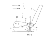
図3に示すように、第1シートベルトバックル10は下端部側の横軸芯O周りに回転自在に構成されて、第1シートベルトバックル10の一部分(上端部の両コーナー部のうちシート後方側Rrの上端部部分)がバックル収容孔Hから上方に突出した状態と、第1シートベルトバックル10がバックル収容孔H内に引退した状態とに切り換え自在に構成されている。第1シートベルトバックル10の下端部は、第1ブラケット11の上端部の保持部に摩擦保持されている。
As shown in FIG. 3, the first
この構成によれば、第1シートベルトバックル10の一部分がバックル収容孔Hから上方に突出した状態に設定することで、シートベルトのタングを第1シートバック10に挿入係合させやすくすることができる。また、第1シートベルトバックル10がバックル収容孔H内に引退した状態に設定することで、バックル収容孔Hに収容された第1シートベルトバックル10が乗員に当接することを回避でき、第1シートベルトバックル10が乗員に異物感を与えることを防止することができる。
According to this configuration, by setting a part of the first
そして、図3,図4に示すように、フロア5側の第2ブラケット21に一端部を固定されたウェビング22が、第1シートベルトバックル10とシート前後方向に並んでシート後方側Rrに位置するようにバックル収容孔Hに挿通され、第2シートベルトバックル20の基端部がウェビング22の他端部に連結されてバックル収容孔Hの上外側に位置している。
As shown in FIGS. 3 and 4, the
例えば、第1シートベルトバックル10と第2シートベルトバックル20がシート幅方向に並んだ構造ではシートクッション2の座面の幅が短くなるが、本実施形態では第1シートベルトバックル10と第2シートベルトバックル20がシート前後方向に並んでいるから、シートクッション2の座面をシート幅方向に広く取ることができる。
For example, in the structure in which the first
そして、上記のように、第1シートベルトバックル10はバックル収容孔Hに収容され、第2シートベルトバックル20はウェビング22を介してフロア5に固定され、ウェビング22がバックル収容孔Hに挿通されているから、第1シートベルトバックル10に差し込んだシートベルトのタングと、第2シートベルトバックル20に差し込んだシートベルトのタングとの干渉を回避することができる。
As described above, the first
図2に示すように、第1ブラケット11と第2ブラケット21は板面がシート幅方向を向く細長い縦板状に形成されている。そして、第1ブラケット11と第2ブラケット21の下端部の折曲した取り付け部12,23同士が上下に重ね合わされ、フロア5にボルトBで共締め固定されて、第1ブラケット11と第2ブラケット21がフロア5から立ち上がっている。
As shown in FIG. 2, the
第1ブラケット11は、前記取り付け部12を構成する断面L字形の取り付け片13と、この取り付け片13の立ち上がり部に下端部がかしめ固定された上下方向に長い第1ブラケット本体部14とから成り、第2ブラケット21よりもシート前方側Frに位置している。第2ブラケット21は単一の金属板から成り、下端部がL字状に折曲されて、L字状の下端部が取り付け部23に構成されている。
The
そして、前記ウェビング22に樹脂製のブーツ30が外挿されてかしめ固定されるとともにブーツ30がバックル収容孔Hに挿入・嵌合され、ブーツ30と第1シートベルトバックル10がバックル収容孔Hを塞いで、バックル収容孔Hに上方から物品(例えばコイン等の小物)が侵入することを阻止している。
A
図5,図6に示すように、前記バックル収容孔Hの上側開口の周縁部H1に、バックル収容孔Hへの物品(例えば、コイン等の小物)の侵入落下を阻止する阻止壁50が上側開口の全周にわたって立設されている。第1シートベルトバックル10は前記阻止壁50に内嵌している。
As shown in FIGS. 5 and 6, a blocking
前記阻止壁50は、シートクッション2の表皮材52と同一材質の阻止壁形成部材51を表皮材52に縫着して構成され、阻止壁形成部材51に覆われるカーペットから成る芯材54が阻止壁形成部材51と表皮材52に共縫いされている。符号Lは縫着ラインを示している。
The blocking
前記阻止壁形成部材51と芯材54の表皮材52への縫着について説明すると、図5に示すように、芯材54が、バックル収容孔Hの長手方向に長い長方形状の一対の阻止壁形成部材51に挟み込まれ、これら三者がバックル収容孔Hの内側面の表皮材52の上下複数箇所に縫着されている。
The sewing of the blocking
一方の阻止壁形成部材51の上端部は他方の阻止壁形成部材51の上端部側に折り返され、他方の阻止壁形成部材51の上端部は一方の阻止壁形成部材51の上端部側に折り返されて、一対の第1折り返し部53同士が互いに縫着されている。一対の第1折り返し部53はバックル収容孔Hの上方に突出している。
The upper end of one blocking
また、バックル収容孔Hの内側面を形成する表皮材52が上下に分割されるとともに、上側の表皮材52の分割端部52T1と下側の表皮材52の分割端部52T2がバックル収容孔Hの径方向(長径方向)で重なるように、下側の表皮材52の分割端部52T2が上方に延出されて、上側の表皮材52の分割端部52T1よりもバックル収容孔Hの径方向内方側に位置している。
そして、下側の表皮材52の分割端部52T2が上側の表皮材52の分割端部52T1側に折り返され、その第2折り返し部59が上側の表皮材52の分割端部52T1にバックル収容孔Hの内方側から重ね合わされて縫着されている。これにより、バックル収容孔Hの内側面の上端部がバックル収容孔Hのシート幅方向の内方側(バックル収容孔Hの径方向内方側)に膨出し、前記第2折り返し部59に重なる前記第1折り返し部53が上方側ほどバックル収容孔Hのシート幅方向内方側に位置するように傾斜している。
前記バックル収容孔Hの両内側面の下半部は下広がりに形成されている(図5参照)。
In addition, the
The divided end portion 52T2 of the
The lower half portions of both inner side surfaces of the buckle housing hole H are formed to spread downward (see FIG. 5).
上記の構成により、第1折り返し部53を第1シートベルトバックル10の上端部に確実に当接させることができ、バックル収容孔Hのシート幅方向の両内側面(内周部に相当)と第1シートベルトバックル10との間の隙間、及び、バックル収容孔Hの両内側面とブーツ30との間の隙間を確実に塞ぐことができる。
With the above configuration, the first folded
前記バックル収容孔Hの左側の内側面に縫着された前記阻止壁形成部材51及び芯材54と、前記バックル収容孔Hの右側の内側面に縫着された前記阻止壁形成部材51及び芯材54とはバックル収容孔Hのシート幅方向の中心に対して左右対称に位置している。
The blocking
前記芯材54を構成するカーペットは、所謂ニードルパンチカーペットと呼ばれるPPなどの樹脂繊維の塊に、返し形状が付いた針(ニードル)を繰返し刺すとともに絡ませて構成され、プレス加工等により平面状に形成されている。前記芯材54はカーペットに限られるものではなく、他の部材で構成されていてもよい。
The carpet constituting the
上記の構成によれば、シートクッション2の座面に落下してバックル収容孔Hに向かう物品(例えばコイン等の小物)を、バックル収容孔Hの上側開口の周縁部H1に立設された阻止壁50で受け止めて、物品がバックル収容孔Hに侵入することを阻止することができる。
そして、組み付け工程においては、シートクッション2より先にフロア5に第1シートベルトバックル10を組み付けておき、シートクッション2をフロア5に上方から載置するに伴なって、第1シートベルトバックル10をバックル収容孔Hに下方から挿入することができる。
この組み付け工程において第1シートベルトバックル10を袋状のバックル収納部のバックル挿通孔に挿通させる構造では、バックル挿通孔を大きくすると、コイン等の小物がバックル挿通孔を通ってバックル収容孔からシートクッションの下方に落下することからバックル挿通孔を大きく設定できず、そのために、第1シートベルトバックル10をバックル挿通孔に挿通させにくい不具合がある。
これに対して、本発明の上記構成によれば、袋状のバックル収納部のバックル挿通孔にシートベルトバックルを挿通させることはないから上記の不具合がない。従って、組み付け作業の作業性を向上させることができる。
According to the above configuration, an article (such as a coin or the like) that falls on the
In the assembling step, the first
In this assembly process, in the structure in which the first
On the other hand, according to the above-described configuration of the present invention, the seat belt buckle is not inserted into the buckle insertion hole of the bag-like buckle storage portion, so that the above-described problem does not occur. Therefore, the workability of the assembly work can be improved.
前記阻止壁50は、シートクッション2の表皮材52と同一材質の阻止壁形成部材51を表皮材52に縫着して構成されているから、阻止壁50の形状・寸法をバックル収容孔Hに対応させて自由に変更でき、種々のバックル収容孔Hの構造に対応できる。また、自然な外観を損なうことがなく、外観品質を向上させることができる。
本発明のシートベルトバックルの収容構造では、第1シートベルトバックル10を下端部側の横軸芯O周りに揺動自在に構成していることから、バックル収容孔H内への第1シートベルトバックル10の引退を阻止壁50が妨げないようにする必要があるが、本発明の上記構成によれば、阻止壁50は表皮材52と同一材質の部材で形成されており、第1シートベルトバックル10が下端部側の横軸芯O周りに揺動回転して阻止壁50に当接しても阻止壁50が適度に撓むことができるので、第1シートベルトバックル10の揺動回転を阻止壁50が妨げることを抑制することができる。
また、シートバック3がシートクッション2の上に前倒しできるタイプのシートの場合、シートバック3に押されて阻止壁50は容易に撓むので、シートバック3を前倒しする時の邪魔になることがない。
Since the blocking
In the seat belt buckle housing structure of the present invention, since the first
When the seat back 3 is a type of seat that can be moved forward on the
前記阻止壁形成部材51に覆われる芯材54が阻止壁形成部材51と表皮材52に共縫いされているので、阻止壁50の剛性を強くすることができる。その結果、シートクッション2の座面に落下してバックル収容孔Hに向かう物品(例えばコイン等の小物)を阻止壁50で確実に受け止めることができ、物品がバックル収容孔Hに侵入することをより阻止しやすくすることができる。しかも、阻止壁50の形態が安定し、外観品質を向上させることができる。
Since the
[別実施形態]
以下、本発明の第1の別実施形態と第2の別実施形態と第3の別実施形態を説明する。
図7〜図10に示すように、第1の別実施形態〜第3の別実施形態では、上記の第1の実施形態と同様に、バックル収容孔Hの内側面を形成する表皮材52が上下に分割されるとともに、上側の表皮材52の分割端部52T1と下側の表皮材52の分割端部52T2がバックル収容孔Hの径方向で重なるように、下側の表皮材52の分割端部52T2が上方に延出されて、上側の表皮材52の分割端部52T1よりもバックル収容孔Hの径方向内方側に位置している。
[Another embodiment]
Hereinafter, a first alternative embodiment, a second alternative embodiment, and a third alternative embodiment of the present invention will be described.
As shown in FIGS. 7 to 10, in the first alternative embodiment to the third alternative embodiment, the
(第1の別実施形態)
図7に示すように、前記阻止壁50は、上端部に断面円形の玉縁55Gが形成された玉縁材55の下端部を表皮材52に縫着して構成されている。この構成によれば、更に自然な外観が得られ、デザイン性が向上する。
前記玉縁材55は、表皮材52と同一の材質の部材を、上端部に断面円形の玉縁55Gが形成されるように折曲して構成されている。そして、前記上側の表皮材52の分割端部52T1と下側の表皮材52の分割端部52T2とに玉縁材55の下端部が挟み込まれて三者が一体に共縫いされている。
詳しくは、前記下側の表皮材52の分割端部52T2が上側の表皮材52の分割端部52T1側に折り返され、その第2折り返し部59と上側の表皮材52の分割端部52T1とで玉縁材55の下端部を挟み込んだ状態で、前記三者が一体に共縫いされている。
前記玉縁材55は表皮材52とは別の材質で構成されていてもよい。
(First alternative embodiment)
As shown in FIG. 7, the blocking
The
Specifically, the divided end portion 52T2 of the
The
(第2の別実施形態)
図8に示すように、上端部に断面円形の玉縁55Gが膨出形成された玉縁材55が樹脂材で押し出し成形され、玉縁材55の平板状の下端部が前記上側の表皮材52の分割端部52T1と下側の表皮材52の分割端部52T2とに挟み込まれて三者が一体に共縫いされている。この構成によれば、更に自然な外観が得られ、デザイン性が向上し、しかも玉縁材55の成形が容易で製作コストを低廉化することができる。
前記下側の表皮材52の分割端部52T2は、前記第1の別実施形態と同様に上側の表皮材52の分割端部52T2側に折り返され、その第2折り返し部59と上側の表皮材52の分割端部52T1とで玉縁材55の平板状の下端部を挟み込んだ状態で、前記三者が一体に共縫いされている。
(Second alternative embodiment)
As shown in FIG. 8, a
The split end portion 52T2 of the
(第3の別実施形態)
図9,図10に示すように、下方に折り畳まれた阻止壁形成部材51の下部の端部(下端部)が、前記上側の表皮材52の分割端部52T1と下側の表皮材52の分割端部52T2とに挟み込まれて三者が一体に共縫いされ、阻止壁形成部材51の上部がバックル収容孔Hの上側開口の周縁部H1から上方に突出して前記阻止壁50を構成している。
この構成によれば、阻止壁50の縫製構造を簡素化することができて、使用する阻止壁形成部材51の量を少なくすることができるとともに、阻止壁形成部材51の縫製長さを短くすることができ、生産品質の安定化・製作コストの低廉化・軽量化を図ることができる。
前記下側の表皮材52の分割端部52T2は、前記第1の別実施形態や第2の別実施形態と同様に、上側の表皮材52の分割端部52T1側に折り返され、その第2折り返し部59と上側の表皮材52の分割端部52T1とで阻止壁形成部材51の下端部を挟み込んだ状態で、前記三者が一体に共縫いされている。
(Third alternative embodiment)
As shown in FIGS. 9 and 10, the lower end portion (lower end portion) of the blocking
According to this configuration, the sewing structure of the blocking
The split end portion 52T2 of the
(1) 前記第1の別実施形態〜第3の別実施形態では、前記阻止壁形成部材51の下端部や玉縁材55の下端部が、前記上側の表皮材52の分割端部52T1と下側の表皮材52の分割端部52T2とに挟み込まれて一体に共縫いされているから、シートクッション2の表皮材52に対する阻止壁形成部材51の縫製強度や、前記表皮材52に対する玉縁材55の縫製強度を強くすることができる。
(1) In the first alternative embodiment to the third alternative embodiment, the lower end portion of the blocking
(2) 前記第1の実施形態、及び前記第1の別実施形態〜第3の別実施形態において、上側の表皮材52の分割端部52T1と下側の表皮材52の分割端部52T2がバックル収容孔Hの径方向で重なるように、上側の表皮材52の分割端部52T1が下方に延出されて、下側の表皮材52の分割端部52T2よりもバックル収容孔Hの径方向内方側に位置し、前記三者(上側の表皮材52の分割端部52T1と下側の表皮材52の分割端部52T2と玉縁材55の下端部、又は、上側の表皮材52の分割端部52T1と下側の表皮材52の分割端部52T2と阻止壁形成部材51の下部)が一体に共縫いされていてもよい。
(2) In the first embodiment and the first to third embodiments, the divided end portion 52T1 of the
2 シートクッション
5 フロア
10 シートベルトバックル(第1シートベルトバックル)
11 フロア側の固定部(第1ブラケット)
50 阻止壁
51 阻止壁形成部材
52 表皮材
52T1 上側の表皮材の分割端部
52T2 下側の表皮材の分割端部
54 芯材
55 玉縁材
55G 玉縁
H バックル収容孔
H1 バックル収容孔の上側開口の周縁部
2
11 Fixed part on the floor side (first bracket)
50
Claims (6)
フロア側の固定部に固定されたシートベルトバックルが前記バックル収容孔に収容されているシートベルトバックルの収容構造であって、
前記バックル収容孔の内側面及び上側開口の周縁部に、前記バックル収容孔への物品の侵入落下を阻止する阻止壁が立設され、
前記シートベルトバックルは前記バックル収容孔内で前記阻止壁に内嵌し、
前記阻止壁の上部の嵌合壁面が前記バックル収容孔内で前記シートベルトバックルの側面に面接触して、前記阻止壁の上部が上下方向に沿うとともに、前記阻止壁の上端部が前記バックル収容孔の上方に突出していて、
前記阻止壁は、芯材と、前記芯材を挟み込んで覆う一対の阻止壁形成部材とを、前記バックル収容孔の内側面の表皮材に縫着して構成されるシートベルトバックルの収容構造。 A buckle accommodation hole is formed in the seat cushion,
A seat belt buckle housing structure in which a seat belt buckle fixed to a fixed portion on the floor side is housed in the buckle housing hole,
On the inner side surface of the buckle housing hole and the peripheral edge of the upper opening, a blocking wall for preventing the entry and dropping of the article into the buckle housing hole is erected,
The seat belt buckle is fitted into the blocking wall in the buckle receiving hole,
The fitting wall surface at the top of the blocking wall is in surface contact with the side surface of the seat belt buckle in the buckle receiving hole, the upper portion of the blocking wall is along the vertical direction, and the upper end of the blocking wall is stored in the buckle. Protruding above the hole ,
A seat belt buckle housing structure in which the blocking wall is formed by sewing a core material and a pair of blocking wall forming members sandwiching and covering the core material to a skin material on an inner surface of the buckle housing hole .
前記他方の阻止壁形成部材の上端部は前記一方の阻止壁形成部材の上端部側に折り返されて、一対の折り返し部同士が互いに縫着され、
前記一対の折り返し部が前記バックル収容孔の上方に突出している請求項1記載のシートベルトバックルの収容構造。 The upper end of one of the blocking wall forming member is folded back to the upper end side of the other of the blocking wall forming member,
The upper end portion of the other blocking wall forming member is folded back to the upper end portion side of the one blocking wall forming member, and the pair of folded portions are sewn together,
The seat belt buckle housing structure according to claim 1, wherein the pair of folded portions protrude above the buckle housing hole.
前記バックル収容孔の内側面を形成する表皮材が上下に分割されるとともに、上側の表皮材の分割端部と下側の表皮材の分割端部が前記バックル収容孔の径方向で重なるように、前記上側の表皮材の分割端部又は下側の表皮材の分割端部が下方又は上方に延出され、
阻止壁形成部材の下部が前記上側の表皮材の分割端部と下側の表皮材の分割端部に挟み込まれて一体に共縫いされ、
前記阻止壁形成部材の上部が前記バックル収容孔の上側開口の周縁部から上方に突出して前記阻止壁を構成している請求項1記載のシートベルトバックルの収容構造。 The skin material of the seat cushion enters the buckle accommodation hole to form the inner surface of the buckle accommodation hole,
The skin material forming the inner side surface of the buckle housing hole is vertically divided, and the split end portion of the upper skin material and the split end portion of the lower skin material overlap in the radial direction of the buckle housing hole. The split end of the upper skin material or the split end of the lower skin material extends downward or upward;
The lower part of the blocking wall forming member is sandwiched between the divided end portion of the upper skin material and the divided end portion of the lower skin material, and integrally sewn together,
The seat belt buckle housing structure according to claim 1, wherein an upper portion of the blocking wall forming member protrudes upward from a peripheral portion of the upper opening of the buckle housing hole to constitute the blocking wall.
Priority Applications (1)
| Application Number | Priority Date | Filing Date | Title |
|---|---|---|---|
| JP2011268041A JP5954560B2 (en) | 2010-12-13 | 2011-12-07 | Seat belt buckle housing structure |
Applications Claiming Priority (3)
| Application Number | Priority Date | Filing Date | Title |
|---|---|---|---|
| JP2010277135 | 2010-12-13 | ||
| JP2010277135 | 2010-12-13 | ||
| JP2011268041A JP5954560B2 (en) | 2010-12-13 | 2011-12-07 | Seat belt buckle housing structure |
Publications (2)
| Publication Number | Publication Date |
|---|---|
| JP2012140119A JP2012140119A (en) | 2012-07-26 |
| JP5954560B2 true JP5954560B2 (en) | 2016-07-20 |
Family
ID=46676861
Family Applications (1)
| Application Number | Title | Priority Date | Filing Date |
|---|---|---|---|
| JP2011268041A Active JP5954560B2 (en) | 2010-12-13 | 2011-12-07 | Seat belt buckle housing structure |
Country Status (1)
| Country | Link |
|---|---|
| JP (1) | JP5954560B2 (en) |
Families Citing this family (4)
| Publication number | Priority date | Publication date | Assignee | Title |
|---|---|---|---|---|
| US9358946B2 (en) * | 2013-09-19 | 2016-06-07 | Edward Sucato | Seatbelt lift member and method |
| JP2018052256A (en) * | 2016-09-28 | 2018-04-05 | セーレン株式会社 | Seat cover for vehicle and method for attaching the same |
| JP7043709B2 (en) * | 2018-10-04 | 2022-03-30 | トヨタ車体株式会社 | Buckle device and buckle device mounting structure |
| JP7507112B2 (en) | 2021-03-09 | 2024-06-27 | 日本発條株式会社 | Vehicle seat |
Family Cites Families (6)
| Publication number | Priority date | Publication date | Assignee | Title |
|---|---|---|---|---|
| JP2509666Y2 (en) * | 1990-10-23 | 1996-09-04 | 株式会社タチエス | Structure of seat belt buckle take-out part in automobile seat |
| JPH0542009U (en) * | 1991-11-13 | 1993-06-08 | 東京シート株式会社 | Belt equipment structure for seat belt backpack in seat cushion |
| JPH06278570A (en) * | 1993-03-26 | 1994-10-04 | Ikeda Bussan Co Ltd | Seat for vehicle |
| JPH06278571A (en) * | 1993-03-26 | 1994-10-04 | Ikeda Bussan Co Ltd | Seat for vehicle |
| JPH0930369A (en) * | 1995-07-17 | 1997-02-04 | Mitsubishi Motors Corp | Belt buckle mounting structure |
| JP2010064639A (en) * | 2008-09-11 | 2010-03-25 | Tachi S Co Ltd | Buckle storage structure for seat belt |
-
2011
- 2011-12-07 JP JP2011268041A patent/JP5954560B2/en active Active
Also Published As
| Publication number | Publication date |
|---|---|
| JP2012140119A (en) | 2012-07-26 |
Similar Documents
| Publication | Publication Date | Title |
|---|---|---|
| JP5954560B2 (en) | Seat belt buckle housing structure | |
| JP5822183B2 (en) | Buckle storage structure | |
| US9352676B1 (en) | Vehicle seating arrangement | |
| US9656579B2 (en) | Headrest and vehicle seat | |
| JP5664902B2 (en) | Seat belt buckle support structure | |
| JP6904807B2 (en) | Vehicle seat | |
| JP5729675B2 (en) | Seat belt buckle housing structure | |
| JP5733508B2 (en) | Vehicle seat | |
| JP2007118757A (en) | Vehicular seat | |
| US10286819B2 (en) | Vehicle interior structure | |
| CN104417409A (en) | Seat back | |
| JP6021636B2 (en) | Vehicle seat | |
| JP2012111409A (en) | Belt buckle drop prevention structure of seat belt | |
| KR101848136B1 (en) | Goods support for car | |
| JP7096474B2 (en) | Vehicle seat | |
| JP6659510B2 (en) | Vehicle seat back | |
| JP5617775B2 (en) | Seat belt buckle storage structure | |
| JP3760600B2 (en) | Automotive seat structure | |
| JP3177315U (en) | Headrest hook | |
| JP5424321B2 (en) | Armrest | |
| JP7096475B2 (en) | Vehicle seat | |
| JP6438065B2 (en) | Seat and reinforcement member cover | |
| JP4467408B2 (en) | Headrest and manufacturing method thereof | |
| JP2516840Y2 (en) | Seat belt storage structure | |
| JP6169476B2 (en) | Vehicle seat |
Legal Events
| Date | Code | Title | Description |
|---|---|---|---|
| A621 | Written request for application examination |
Free format text: JAPANESE INTERMEDIATE CODE: A621 Effective date: 20140715 |
|
| A977 | Report on retrieval |
Free format text: JAPANESE INTERMEDIATE CODE: A971007 Effective date: 20150319 |
|
| A131 | Notification of reasons for refusal |
Free format text: JAPANESE INTERMEDIATE CODE: A131 Effective date: 20150323 |
|
| A521 | Written amendment |
Free format text: JAPANESE INTERMEDIATE CODE: A523 Effective date: 20150515 |
|
| A131 | Notification of reasons for refusal |
Free format text: JAPANESE INTERMEDIATE CODE: A131 Effective date: 20151112 |
|
| A521 | Written amendment |
Free format text: JAPANESE INTERMEDIATE CODE: A523 Effective date: 20151207 |
|
| TRDD | Decision of grant or rejection written | ||
| A01 | Written decision to grant a patent or to grant a registration (utility model) |
Free format text: JAPANESE INTERMEDIATE CODE: A01 Effective date: 20160519 |
|
| A61 | First payment of annual fees (during grant procedure) |
Free format text: JAPANESE INTERMEDIATE CODE: A61 Effective date: 20160601 |
|
| R151 | Written notification of patent or utility model registration |
Ref document number: 5954560 Country of ref document: JP Free format text: JAPANESE INTERMEDIATE CODE: R151 |