JP5953945B2 - Print medium conveying apparatus and image forming apparatus - Google Patents
Print medium conveying apparatus and image forming apparatus Download PDFInfo
- Publication number
- JP5953945B2 JP5953945B2 JP2012125344A JP2012125344A JP5953945B2 JP 5953945 B2 JP5953945 B2 JP 5953945B2 JP 2012125344 A JP2012125344 A JP 2012125344A JP 2012125344 A JP2012125344 A JP 2012125344A JP 5953945 B2 JP5953945 B2 JP 5953945B2
- Authority
- JP
- Japan
- Prior art keywords
- unit
- print medium
- transport
- contact
- medium
- Prior art date
- Legal status (The legal status is an assumption and is not a legal conclusion. Google has not performed a legal analysis and makes no representation as to the accuracy of the status listed.)
- Active
Links
Images


Description
本発明は、用紙などを搬送する印刷媒体搬送装置、及び画像形成装置に関する。 The present invention relates to a print medium transport apparatus that transports paper and the like, and an image forming apparatus.
従来、画像形成装置などにおいては、原稿や記録用紙等の用紙は印刷媒体搬送装置により用紙トレイから用紙排出部まで順次搬送されていく。印刷媒体搬送装置は、複数のガイド部で構成される搬送路、複数の回転駆動するローラ部を備えており、搬送路内において用紙が搬送される。 2. Description of the Related Art Conventionally, in an image forming apparatus or the like, paper such as a document or recording paper is sequentially transported from a paper tray to a paper discharge unit by a print medium transport device. The print medium conveyance device includes a conveyance path composed of a plurality of guide portions and a plurality of rollers that are driven to rotate, and the sheet is conveyed in the conveyance path.
印刷動作が開始されると、イエロー、マゼンタ、シアン、ブラックの4種類の像担持体において形成されたトナー像が、中間転写ベルトに転写される。一方、用紙トレイから一枚ずつ給紙された用紙は搬送路に沿って2次転写装置に搬送され、中間転写ベルトのトナー像が用紙に転写される。そして、定着ユニットにおいて、用紙に対してトナー像が定着された後、印刷媒体搬送装置から機外に排紙される。 When the printing operation is started, toner images formed on the four types of image carriers of yellow, magenta, cyan, and black are transferred to the intermediate transfer belt. On the other hand, the sheets fed one by one from the sheet tray are transported along the transport path to the secondary transfer device, and the toner image on the intermediate transfer belt is transferred onto the sheet. Then, after the toner image is fixed on the sheet in the fixing unit, the sheet is discharged from the printing medium conveying apparatus to the outside of the apparatus.
この際、用紙の搬送時において斜めに曲がった状態を補正するための斜行補正装置が搬送路には設けられている。斜行補正装置は、用紙の先端をガイド部に突き当てることで先端の位置を揃え、2次転写装置に対して用紙が平行となる状態に位置を補正する。具体的には、斜行補正用のローラと、その上流側に位置する搬送用のローラとの間で、用紙を余分に送り出すことで、用紙の先端をガイド部に突き当てるようにする。このように用紙の整列を行うためには、送り出した用紙分が搬送経路から逃れてたるみが形成されることができる空間が必要であり、そのためには各ローラの間に十分な距離と空間を確保する必要があり、また、剛性が高く厚い用紙ほどその間隔は長く確保しなければならない。 At this time, a skew correction device for correcting a state of being bent obliquely during the conveyance of the sheet is provided in the conveyance path. The skew correction device aligns the position of the leading edge by abutting the leading edge of the sheet against the guide unit, and corrects the position so that the sheet is parallel to the secondary transfer apparatus. Specifically, the leading edge of the paper is abutted against the guide portion by feeding the paper excessively between the skew correction roller and the conveying roller located upstream thereof. In order to align the sheets in this way, a space is required in which a portion of the fed sheets can escape from the conveyance path to form a slack, and for that purpose, a sufficient distance and space must be provided between the rollers. In addition, it is necessary to secure a longer interval between thicker and thicker sheets.
しかしながら近年、プリンタなどの画像形成装置は様々な種類の用紙に対応する必要性が増加してきており、剛性が高い厚紙や、はがきなどの長さが短い用紙などを一台で印刷することが求められるようになってきている。 However, in recent years, there has been an increasing need for image forming apparatuses such as printers to support various types of paper, and it is required to print thick paper with high rigidity, paper with short length such as postcards, etc. in one unit. It is getting to be.
そして、斜行補正装置のようにローラ間で用紙にたるみを形成させる場合、ローラの間隔を短く配置すると、剛性の高い厚紙では紙の腰が強く、搬送用のローラが余分に紙を送り込むことができなくなってしまう。このような場合、例えば、特許文献1に示されるように、ローラ対を上下方向に離間させる機構を設け、さらにその上流側に設けられた別の搬送用のローラによって用紙を搬送する。このようにすることで、離間されたローラには用紙が触れなくなり、上流側のローラと斜行補正用のローラとの間の長いローラピッチでたるみが形成されるようになる。しかしながら、通常短時間の間に行うことができる離間動作は数mm程度であるため、十分なたるみを形成するための空間を確保するためには離間距離が不足し、用紙の送り出しの障害となってしまうという課題があった。 When slack is formed between the rollers as in the skew correction device, if the rollers are arranged at a short interval, the thick paper with high rigidity will be stiff, and the transport roller will feed extra paper. Will not be able to. In such a case, for example, as shown in Patent Document 1, a mechanism for separating the pair of rollers in the vertical direction is provided, and the sheet is conveyed by another conveying roller provided on the upstream side thereof. By doing so, the sheet is not in contact with the separated rollers, and a slack is formed at a long roller pitch between the upstream roller and the skew correction roller. However, the separation operation that can be normally performed in a short time is about several millimeters, so that the separation distance is insufficient to secure a space for forming a sufficient slack, which is an obstacle to sheet feeding. There was a problem that it would end up.
本発明は、上記に鑑みてなされたものであって、印刷媒体を搬送する際に、方向補正のために長さの異なる用紙を十分に送り出すことができる空間を確保可能な印刷媒体搬送装置を提供することにある。 The present invention has been made in view of the above, and provides a printing medium conveyance device capable of ensuring a space that can sufficiently feed out different length sheets for direction correction when conveying a printing medium. It is to provide.
上述した課題を解決し、目的を達成するために、本発明の印刷媒体搬送装置は、印刷媒体が搬送される経路となる搬送路と、前記印刷媒体の搬送方向における前方部と接触して前記印刷媒体の搬送を停止させる接触部と、前記接触部と接触した前記印刷媒体の前記前方部を保持する保持部と、前記印刷媒体を前記接触部に突き当てるように搬送し、前記印刷媒体を保持した前記保持部との間で、前記印刷媒体にたるみを形成させる第1搬送部と、前記第1搬送部よりも前記搬送方向の前記保持部側に設けられ、前記印刷媒体を前記接触部に突き当てるように搬送し、前記印刷媒体を保持した前記保持部との間で、前記印刷媒体にたるみを形成させる第2搬送部が着脱可能な着脱部と、を備え、前記第2搬送部は、前記印刷媒体の上面側、及び下面側にそれぞれ設けられたローラ部と、前記搬送路とは独立して前記印刷媒体を両面からガイドするガイド部と、を備え、前記着脱部は、前記第2搬送部の前記ローラ部と前記ガイド部とを取り外すことができることを特徴とする。 In order to solve the above-described problems and achieve the object, the printing medium conveyance device of the present invention is in contact with a conveyance path serving as a path through which the printing medium is conveyed and a front portion in the conveyance direction of the printing medium. A contact portion for stopping conveyance of the print medium, a holding portion for holding the front portion of the print medium in contact with the contact portion, and conveying the print medium so as to abut against the contact portion. A first conveyance unit that forms a slack in the print medium between the held unit and the holding unit; the first conveyance unit is provided closer to the holding unit in the conveyance direction than the first conveyance unit; transported to abut against the said between said holding part holding the print medium, a second conveying unit, and a removable portion detachable to form slack in the printing medium, the second transport unit Are the upper surface side of the print medium, and A roller portion provided on each side of the surface, and a guide portion that guides the print medium from both sides independently of the conveyance path, and the detachable portion includes the roller portion of the second conveyance portion and the roller portion The guide part can be removed .
本発明の印刷媒体搬送装置は、印刷媒体を搬送する際に、方向補正するために長さの異なる用紙を十分に送り出すことができる空間を確保することができるようになる。 The print medium transport apparatus according to the present invention can secure a space in which sheets of different lengths can be sufficiently sent out to correct the direction when transporting the print medium.
図1は本発明の実施形態における印刷媒体搬送装置を備えた画像形成装置の側面図である。図1に示されるように、画像形成装置100は、給紙装置200、印刷媒体搬送装置300、斜行補正装置400、像担持体500、2次転写装置600、定着装置700を備えている。
FIG. 1 is a side view of an image forming apparatus provided with a print medium conveying apparatus according to an embodiment of the present invention. As shown in FIG. 1, the
像担持体500は、イエロー、マゼンタ、シアン、ブラックの4色の像担持体500Y,500M,500C,500Bkである。また、画像形成装置100は、中間転写ベルト501を備えている。像担持体500Y、500M、500C、500Bkで形成されたトナー像は、中間転写ベルト501に転写される。
The
給紙装置200は、給紙トレイ201a、及び201bから用紙を印刷媒体搬送装置300へと給紙する。給紙トレイ201a、201bには、用紙Sが積載されている。給紙装置200から給紙された用紙Sは、印刷媒体搬送装置300へと搬送される。印刷媒体搬送装置300は、搬送路301、及び搬送用ローラ対302を備えている。搬送路301は、ガイド板によって構成され、搬送路301に沿って用紙Sが搬送される。搬送路301は用紙Sの上面、及び下面の両方から用紙Sを挟み込む構成となっている。搬送用ローラ対302は、搬送路301において複数設けられており、回転軸を支点に駆動されることで回転し、ローラ間に挟持した用紙Sを搬送する。
The
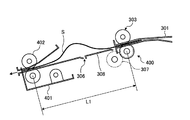
図2は、斜行補正装置400の詳細を示した側面図である。図2に示されるように、印刷媒体搬送装置300は、第1搬送部303、第2搬送部304、及び斜行補正装置400を備えている。斜行補正装置400は、第1搬送部303、第2搬送部304、接触部401、及び保持部402を備えている。
FIG. 2 is a side view showing details of the skew
第1搬送部303、及び第2搬送部304は、用紙Sを整列させるために用紙Sを搬送する。第1搬送部303は、ローラ部303a、及び303bにより構成される。ローラ部303a、及び303bは搬送路301を構成するガイド板に形成された孔より、搬送路301内に突出している。また、第2搬送部304は、ローラ部304a、及び304bと、ガイド部305a、及び305bとを備えている。ガイド部305a、305bは、搬送路301を構成するガイド板と同様に、用紙Sを両面からガイドし、用紙Sの搬送方向を制御するが、搬送路301のガイド板とは連続しておらず、独立した構成となっている。また、ガイド部305a、及び305bには、孔が形成されており、孔からローラ部304a、及び304bが搬送路301内に突出している。
The
また、印刷媒体搬送装置300は、この第2搬送部304を着脱することのできる着脱機構306が設けられている。着脱機構306は、搬送路301のうち、この第2搬送部304を装着する部位にガイド板を設けないことで、空間を形成し、この空間に第2搬送部304をはめ込むことができる。第2搬送部304は、例えば図示しないネジ等の締結手段によって印刷媒体搬送装置300に固定される。第2搬送部304は、したがって、手動で着脱を行うことができるものである。
In addition, the printing
第1搬送部303、及び第2搬送部304は、共通の駆動伝達部307によって駆動される。駆動伝達部307は、第1搬送部303、及び第2搬送部304のそれぞれのローラと接触しており、回転力が伝達されるようになっている。このように駆動部を共用することで、新たに駆動部や制御部を設ける必要がなく、装置のコスト低減が可能となる。なお、駆動伝達部307自体は回転させずに、第1搬送部303における回転が、駆動伝達部307を介して、第2搬送部304に伝達されるようにしてもよい。
The
接触部401は、用紙Sの搬送方向における前方側の部分を接触させて、用紙Sの先端を接触部401に対し平行に整列させる。本実施形態においては、接触部401は、ガイド板が折り曲げられて搬送路301内に突出するような形状に構成されている。第1搬送部303、又は第2搬送部304は、用紙Sが接触部401に接触した後、ある所定の距離分用紙Sを搬送し用紙Sの搬送を一時的に停止する。そして、中間転写ベルト501上に描かれた像が所定の位置に搬送されるのに同期し、第1搬送部303、又は第2搬送部304は用紙Sの搬送を再開し、その際、接触部401は下方へ退避することにより用紙Sが搬送される。なお、後述する保持部402における用紙Sの当接点に突き当てる、いわゆるニップ突き当て方式としても接触部を実現することもできる。この場合、接触部401と保持部402が1つの部材によって兼用されている。
The
保持部402は、搬送方向における用紙Sの前方側を保持するローラ対である。斜行補正装置400は、第1搬送部303、又は第2搬送部304が用紙Sを接触部401に対して突き当てるように搬送した際に、保持部402と第1搬送部303、又は第2搬送部304との間で用紙Sにたるみを形成させることにより、斜行を補正する。図2においては、第2搬送部304が設けられていることから、保持部402と、第2搬送部304との間のL2の距離において用紙Sのたるみが形成されている。このように整列された用紙Sが更に2次転写装置600へと搬送される。そして、2次転写装置600は、中間転写ベルト501に形成されたトナー像を用紙Sへと転写する。ついで定着装置700は、用紙Sに転写されたトナー像を定着させ、用紙Sは画像形成装置100から排紙される。
The holding
また、図3は、印刷媒体搬送装置300から、第2搬送部304を着脱した状態を示す側面図である。図3においては、第2搬送部304を取り外したあとに、別部材であるガイド部308を着脱機構306に形成された空間にかぶせる様に装着させている。なお、ガイド部308は搬送路301とほぼ平行に形成されているが、図4に示されるように、ガイド部308aがたるみの形成される側に突出した形状としてもよい。このような構成にすることで、ガイド部308aを起点にたるみを形成させやすくすることができる。
FIG. 3 is a side view showing a state where the
図3においては、第2搬送部304が存在しないため、用紙Sのたるみは、第1搬送部303と、保持部402との間の距離L1で形成されている。距離L1は図2において示したL2よりも長いため、第2搬送部304がある状態と比較して、より長い用紙Sのサイズでもたるみを形成することができるようになる。
In FIG. 3, since the
図5は、第2搬送部の別の着脱方法を示す側面図である。図5に示されるように、印刷媒体搬送装置3000においては、第2搬送部1304は、ローラ部1304a、1304bと、ガイド部1305a、1305bとを備えている。ガイド部1305bは、搬送路301を構成するガイド板と一体的に構成されており、ローラ部1304b、及びガイド部1305bは着脱部1306からは取り外すことはできない。一方、ローラ部1304a、及びガイド部1305aは、着脱部1306から取り外すことができる。したがって、この例では第2搬送部1304のうち、たるみが形成される側の部分のみが着脱可能に構成されている。
FIG. 5 is a side view showing another method of attaching and detaching the second transport unit. As shown in FIG. 5, in the print
以上に示した印刷媒体搬送装置300においては、はがきなどの短い用紙を印刷する必要が無い場合、斜行補正装置400は図3の構成で使用するようにすればよい。この場合、第1搬送部303と、保持部402との間のローラピッチL1より長さが短い用紙Sは搬送することはできないが、L1以上の用紙であれば、用紙搬送が可能であり、剛性の高い厚紙でもガイド部308を配置したことでたるみを形成する十分な空間が確保されるため、用紙の斜行補正が可能となる。
In the print
一方、長さの短い用紙を印刷する場合には、図2に示した斜行補正装置400の構成で使用するようにすればよい。この場合、用紙Sは第2搬送部304と保持部402との間のローラピッチL2までの用紙Sを搬送することが可能となり、第2搬送部304がない状態では、搬送することができなかった短い用紙も搬送可能となる。
On the other hand, when printing a short sheet, the skew feeding
このような着脱方式を採用すれば、搬送部の位置を変更するための駆動系や制御を行う構成を設ける必要もないため、装置のコストを上げることなくユーザの必要に応じて第2搬送部304を着脱することで、はがきなどの短い用紙と、剛性の高い厚紙の印刷が可能となり、様々な長さの用紙に対応可能な画像形成装置を提供することができるようになる。 If such an attachment / detachment method is adopted, there is no need to provide a drive system or a control structure for changing the position of the transport unit, so that the second transport unit can be provided according to the needs of the user without increasing the cost of the apparatus. By attaching and detaching 304, it is possible to print short paper such as postcards and thick paper with high rigidity, and it is possible to provide an image forming apparatus capable of handling paper of various lengths.
100 画像形成装置
200 給紙装置
201a 給紙トレイ
201b 給紙トレイ
300 印刷媒体搬送装置
301 搬送路
302 搬送用ローラ対
303 第1搬送部
303a ローラ部
303b ローラ部
304 第2搬送部
304a ローラ部
304b ローラ部
305a ガイド部
305b ガイド部
306 着脱機構
307 駆動伝達部
308 ガイド部
308a ガイド部
400 斜行補正装置
401 接触部
402 保持部
500 像担持体
501 中間転写ベルト
600 2次転写装置
700 定着装置
1304 第2搬送部
1304a ローラ部
1304b ローラ部
1305a ガイド部
1305b ガイド部
1306 着脱部
3000 印刷媒体搬送装置
DESCRIPTION OF
Claims (6)
前記印刷媒体の搬送方向における前方部と接触して前記印刷媒体の搬送を停止させる接触部と、
前記接触部と接触した前記印刷媒体の前記前方部を保持する保持部と、
前記印刷媒体を前記接触部に突き当てるように搬送し、前記印刷媒体を保持した前記保持部との間で、前記印刷媒体にたるみを形成させる第1搬送部と、
前記第1搬送部よりも前記搬送方向の前記保持部側に設けられ、前記印刷媒体を前記接触部に突き当てるように搬送し、前記印刷媒体を保持した前記保持部との間で、前記印刷媒体にたるみを形成させる第2搬送部が着脱可能な着脱部と、を備え、
前記第2搬送部は、前記印刷媒体の上面側、及び下面側にそれぞれ設けられたローラ部と、前記搬送路とは独立して前記印刷媒体を両面からガイドするガイド部と、を備え、
前記着脱部は、前記第2搬送部の前記ローラ部と前記ガイド部とを取り外すことができる
ことを特徴とする印刷媒体搬送装置。 A transport path that is a path through which the print medium is transported;
A contact portion that comes into contact with a front portion in the conveyance direction of the print medium and stops conveyance of the print medium;
A holding part for holding the front part of the print medium in contact with the contact part;
A first transport unit that transports the print medium so as to abut against the contact unit, and forms slack in the print medium with the holding unit that holds the print medium;
The printing unit is provided on the holding unit side in the transport direction with respect to the first transport unit, transports the print medium so as to abut against the contact unit, and holds the print medium with the print unit. A detachable part that is detachable from the second transport part for forming a slack in the medium ,
The second transport unit includes a roller unit provided on each of an upper surface side and a lower surface side of the print medium, and a guide unit that guides the print medium from both sides independently of the transport path,
The attachment / detachment part can remove the roller part and the guide part of the second transport part.
Print media transport device, wherein the this.
ことを特徴とする請求項1に記載の印刷媒体搬送装置。 The detachable unit is configured to space is removed and the roller portion and the guide portion of the second conveying section, the printing medium according to claim 1, characterized in that is attachable to another guide portion is a separate member Conveying device.
前記印刷媒体の搬送方向における前方部と接触して前記印刷媒体の搬送を停止させる接触部と、A contact portion that comes into contact with a front portion in the conveyance direction of the print medium and stops conveyance of the print medium;
前記接触部と接触した前記印刷媒体の前記前方部を保持する保持部と、A holding part for holding the front part of the print medium in contact with the contact part;
前記印刷媒体を前記接触部に突き当てるように搬送し、前記印刷媒体を保持した前記保持部との間で、前記印刷媒体にたるみを形成させる第1搬送部と、A first transport unit that transports the print medium so as to abut against the contact unit, and forms slack in the print medium with the holding unit that holds the print medium;
前記第1搬送部よりも前記搬送方向の前記保持部側に設けられ、前記印刷媒体を前記接触部に突き当てるように搬送し、前記印刷媒体を保持した前記保持部との間で、前記印刷媒体にたるみを形成させる第2搬送部が着脱可能な着脱部と、を備え、The printing unit is provided on the holding unit side in the transport direction with respect to the first transport unit, transports the print medium so as to abut against the contact unit, and holds the print medium with the print unit. A detachable part that is detachable from the second transport part for forming a slack in the medium,
前記第2搬送部は、前記印刷媒体の上面側、及び下面側にそれぞれ設けられたローラ部を備え、The second transport unit includes a roller unit provided on each of an upper surface side and a lower surface side of the print medium,
前記着脱部は、前記第2搬送部のうち、前記ローラ部のうち前記たるみが形成される側のローラのみを着脱することができるThe attachment / detachment portion can attach / detach only the roller on the side where the slack is formed in the roller portion of the second transport portion.
ことを特徴とする印刷媒体搬送装置。A print medium conveying apparatus characterized by the above.
更に備えることを特徴とする請求項1〜3のいずれか一項に記載の印刷媒体搬送装置。 The first conveyor, and the printing medium conveying apparatus according to any one of claims 1 to 3, further comprising a driving unit for driving both of the second transporter.
更に備えることを特徴とする請求項1〜3のいずれか一項に記載の印刷媒体搬送装置。 Printing medium feeding apparatus according to claim 1, characterized in that it comprises a rotational force of said first conveyor further transmission unit for transmitting to said second transport section.
Priority Applications (2)
| Application Number | Priority Date | Filing Date | Title |
|---|---|---|---|
| JP2012125344A JP5953945B2 (en) | 2012-05-31 | 2012-05-31 | Print medium conveying apparatus and image forming apparatus |
| US13/905,665 US8905401B2 (en) | 2012-05-31 | 2013-05-30 | Printing medium conveying device and image forming apparatus |
Applications Claiming Priority (1)
| Application Number | Priority Date | Filing Date | Title |
|---|---|---|---|
| JP2012125344A JP5953945B2 (en) | 2012-05-31 | 2012-05-31 | Print medium conveying apparatus and image forming apparatus |
Publications (3)
| Publication Number | Publication Date |
|---|---|
| JP2013249171A JP2013249171A (en) | 2013-12-12 |
| JP2013249171A5 JP2013249171A5 (en) | 2015-06-11 |
| JP5953945B2 true JP5953945B2 (en) | 2016-07-20 |
Family
ID=49848242
Family Applications (1)
| Application Number | Title | Priority Date | Filing Date |
|---|---|---|---|
| JP2012125344A Active JP5953945B2 (en) | 2012-05-31 | 2012-05-31 | Print medium conveying apparatus and image forming apparatus |
Country Status (1)
| Country | Link |
|---|---|
| JP (1) | JP5953945B2 (en) |
Families Citing this family (2)
| Publication number | Priority date | Publication date | Assignee | Title |
|---|---|---|---|---|
| JP2016081007A (en) | 2014-10-22 | 2016-05-16 | 株式会社リコー | Conveyance device, image forming apparatus, and conveyance control method |
| US10054895B2 (en) | 2015-05-14 | 2018-08-21 | Ricoh Company, Ltd. | Image forming apparatus and image forming method |
Family Cites Families (4)
| Publication number | Priority date | Publication date | Assignee | Title |
|---|---|---|---|---|
| JP3749778B2 (en) * | 1997-05-21 | 2006-03-01 | 株式会社リコー | Paper transport device |
| JP2001233507A (en) * | 2000-02-18 | 2001-08-28 | Fuji Photo Film Co Ltd | Sheet body feeder |
| JP2002104696A (en) * | 2000-09-26 | 2002-04-10 | Konica Corp | Image forming device |
| JP4385627B2 (en) * | 2003-03-24 | 2009-12-16 | 富士ゼロックス株式会社 | Sheet conveying apparatus and sheet processing apparatus using the same |
-
2012
- 2012-05-31 JP JP2012125344A patent/JP5953945B2/en active Active
Also Published As
| Publication number | Publication date |
|---|---|
| JP2013249171A (en) | 2013-12-12 |
Similar Documents
| Publication | Publication Date | Title |
|---|---|---|
| US8905401B2 (en) | Printing medium conveying device and image forming apparatus | |
| US20130221612A1 (en) | Image forming apparatus | |
| JP4856231B2 (en) | Media transport mechanism | |
| US7953354B2 (en) | Transfer belt unit for image forming apparatus | |
| JP5825021B2 (en) | Tractor unit and printer | |
| JP5953945B2 (en) | Print medium conveying apparatus and image forming apparatus | |
| US8643686B2 (en) | Variable rate fuser release fluid application | |
| JP6201396B2 (en) | Print medium conveying apparatus and image forming apparatus | |
| US7954807B2 (en) | Sheet-feeding device and image forming apparatus provided with the same | |
| JP2007304430A (en) | Image forming apparatus | |
| JP5401887B2 (en) | Image forming apparatus | |
| JP2010024036A (en) | Paper feeder, image forming apparatus, and image forming system | |
| US7581729B2 (en) | Sheet conveying apparatus and image forming apparatus | |
| US8837987B2 (en) | Image forming apparatus with first and second interlocking doors | |
| JP2011251786A (en) | Discharge device and image forming apparatus | |
| JP4563963B2 (en) | Paper transport device, image forming device | |
| CN210199513U (en) | Sheet post-processing apparatus and image forming apparatus | |
| US10766724B2 (en) | Sheet conveyance device and image forming apparatus | |
| JP5574884B2 (en) | Image forming apparatus | |
| JPH11322137A (en) | Feeding paper carrier device | |
| JP2008044683A (en) | Paper feeder and image forming device | |
| JP2018136378A (en) | Sheet processing device | |
| JP2008265979A (en) | Paper feeder and image forming device mounted with the paper feeder | |
| JP2007290402A (en) | Paper feeding device | |
| JP2018080031A (en) | Medium transport device and image forming apparatus |
Legal Events
| Date | Code | Title | Description |
|---|---|---|---|
| A521 | Written amendment |
Free format text: JAPANESE INTERMEDIATE CODE: A523 Effective date: 20150421 |
|
| A621 | Written request for application examination |
Free format text: JAPANESE INTERMEDIATE CODE: A621 Effective date: 20150421 |
|
| A977 | Report on retrieval |
Free format text: JAPANESE INTERMEDIATE CODE: A971007 Effective date: 20160317 |
|
| A131 | Notification of reasons for refusal |
Free format text: JAPANESE INTERMEDIATE CODE: A131 Effective date: 20160329 |
|
| A521 | Written amendment |
Free format text: JAPANESE INTERMEDIATE CODE: A523 Effective date: 20160420 |
|
| TRDD | Decision of grant or rejection written | ||
| A01 | Written decision to grant a patent or to grant a registration (utility model) |
Free format text: JAPANESE INTERMEDIATE CODE: A01 Effective date: 20160517 |
|
| A61 | First payment of annual fees (during grant procedure) |
Free format text: JAPANESE INTERMEDIATE CODE: A61 Effective date: 20160530 |
|
| R151 | Written notification of patent or utility model registration |
Ref document number: 5953945 Country of ref document: JP Free format text: JAPANESE INTERMEDIATE CODE: R151 |