JP5952855B2 - Packing tool - Google Patents
Packing tool Download PDFInfo
- Publication number
- JP5952855B2 JP5952855B2 JP2014100790A JP2014100790A JP5952855B2 JP 5952855 B2 JP5952855 B2 JP 5952855B2 JP 2014100790 A JP2014100790 A JP 2014100790A JP 2014100790 A JP2014100790 A JP 2014100790A JP 5952855 B2 JP5952855 B2 JP 5952855B2
- Authority
- JP
- Japan
- Prior art keywords
- inner bag
- support frame
- posture
- covering portion
- pair
- Prior art date
- Legal status (The legal status is an assumption and is not a legal conclusion. Google has not performed a legal analysis and makes no representation as to the accuracy of the status listed.)
- Active
Links
- 238000012856 packing Methods 0.000 title claims description 32
- 238000003780 insertion Methods 0.000 claims description 27
- 230000037431 insertion Effects 0.000 claims description 27
- 230000002093 peripheral effect Effects 0.000 claims description 22
- 238000004806 packaging method and process Methods 0.000 claims description 3
- 230000003139 buffering effect Effects 0.000 description 13
- 230000009471 action Effects 0.000 description 5
- 239000000463 material Substances 0.000 description 5
- 229920005989 resin Polymers 0.000 description 5
- 239000011347 resin Substances 0.000 description 5
- 238000000034 method Methods 0.000 description 4
- 238000007789 sealing Methods 0.000 description 4
- 229920003002 synthetic resin Polymers 0.000 description 4
- 239000000057 synthetic resin Substances 0.000 description 4
- 238000005452 bending Methods 0.000 description 2
- 230000006872 improvement Effects 0.000 description 2
- 230000001747 exhibiting effect Effects 0.000 description 1
- 238000000605 extraction Methods 0.000 description 1
- 239000004744 fabric Substances 0.000 description 1
- 239000006260 foam Substances 0.000 description 1
- 239000011521 glass Substances 0.000 description 1
- 239000002184 metal Substances 0.000 description 1
- 230000004048 modification Effects 0.000 description 1
- 238000012986 modification Methods 0.000 description 1
- 230000008569 process Effects 0.000 description 1
- 230000035939 shock Effects 0.000 description 1
- 230000002195 synergetic effect Effects 0.000 description 1
- 239000002023 wood Substances 0.000 description 1
Images


Classifications
-
- B—PERFORMING OPERATIONS; TRANSPORTING
- B65—CONVEYING; PACKING; STORING; HANDLING THIN OR FILAMENTARY MATERIAL
- B65D—CONTAINERS FOR STORAGE OR TRANSPORT OF ARTICLES OR MATERIALS, e.g. BAGS, BARRELS, BOTTLES, BOXES, CANS, CARTONS, CRATES, DRUMS, JARS, TANKS, HOPPERS, FORWARDING CONTAINERS; ACCESSORIES, CLOSURES, OR FITTINGS THEREFOR; PACKAGING ELEMENTS; PACKAGES
- B65D81/00—Containers, packaging elements, or packages, for contents presenting particular transport or storage problems, or adapted to be used for non-packaging purposes after removal of contents
- B65D81/02—Containers, packaging elements, or packages, for contents presenting particular transport or storage problems, or adapted to be used for non-packaging purposes after removal of contents specially adapted to protect contents from mechanical damage
- B65D81/05—Containers, packaging elements, or packages, for contents presenting particular transport or storage problems, or adapted to be used for non-packaging purposes after removal of contents specially adapted to protect contents from mechanical damage maintaining contents at spaced relation from package walls, or from other contents
- B65D81/07—Containers, packaging elements, or packages, for contents presenting particular transport or storage problems, or adapted to be used for non-packaging purposes after removal of contents specially adapted to protect contents from mechanical damage maintaining contents at spaced relation from package walls, or from other contents using resilient suspension means
- B65D81/075—Containers, packaging elements, or packages, for contents presenting particular transport or storage problems, or adapted to be used for non-packaging purposes after removal of contents specially adapted to protect contents from mechanical damage maintaining contents at spaced relation from package walls, or from other contents using resilient suspension means the contents being located between two membranes stretched between opposed sides of the package
-
- B—PERFORMING OPERATIONS; TRANSPORTING
- B65—CONVEYING; PACKING; STORING; HANDLING THIN OR FILAMENTARY MATERIAL
- B65D—CONTAINERS FOR STORAGE OR TRANSPORT OF ARTICLES OR MATERIALS, e.g. BAGS, BARRELS, BOTTLES, BOXES, CANS, CARTONS, CRATES, DRUMS, JARS, TANKS, HOPPERS, FORWARDING CONTAINERS; ACCESSORIES, CLOSURES, OR FITTINGS THEREFOR; PACKAGING ELEMENTS; PACKAGES
- B65D81/00—Containers, packaging elements, or packages, for contents presenting particular transport or storage problems, or adapted to be used for non-packaging purposes after removal of contents
- B65D81/02—Containers, packaging elements, or packages, for contents presenting particular transport or storage problems, or adapted to be used for non-packaging purposes after removal of contents specially adapted to protect contents from mechanical damage
- B65D81/05—Containers, packaging elements, or packages, for contents presenting particular transport or storage problems, or adapted to be used for non-packaging purposes after removal of contents specially adapted to protect contents from mechanical damage maintaining contents at spaced relation from package walls, or from other contents
- B65D81/07—Containers, packaging elements, or packages, for contents presenting particular transport or storage problems, or adapted to be used for non-packaging purposes after removal of contents specially adapted to protect contents from mechanical damage maintaining contents at spaced relation from package walls, or from other contents using resilient suspension means
-
- B—PERFORMING OPERATIONS; TRANSPORTING
- B65—CONVEYING; PACKING; STORING; HANDLING THIN OR FILAMENTARY MATERIAL
- B65D—CONTAINERS FOR STORAGE OR TRANSPORT OF ARTICLES OR MATERIALS, e.g. BAGS, BARRELS, BOTTLES, BOXES, CANS, CARTONS, CRATES, DRUMS, JARS, TANKS, HOPPERS, FORWARDING CONTAINERS; ACCESSORIES, CLOSURES, OR FITTINGS THEREFOR; PACKAGING ELEMENTS; PACKAGES
- B65D5/00—Rigid or semi-rigid containers of polygonal cross-section, e.g. boxes, cartons or trays, formed by folding or erecting one or more blanks made of paper
- B65D5/42—Details of containers or of foldable or erectable container blanks
- B65D5/44—Integral, inserted or attached portions forming internal or external fittings
- B65D5/50—Internal supporting or protecting elements for contents
- B65D5/5028—Elements formed separately from the container body
- B65D5/5035—Paper elements
- B65D5/5059—Paper panels presenting one or more openings or recesses in wich at least a part of the contents are located
Landscapes
- Engineering & Computer Science (AREA)
- Mechanical Engineering (AREA)
- Buffer Packaging (AREA)
- Packages (AREA)
Description
本発明は、例えば、電気機器等の商品(被梱包物の一例)が運搬時に損傷するのを防止する等の目的で商品を梱包するのに用いられる梱包具に関する。 The present invention relates to a packing device used for packing a product for the purpose of preventing a product (an example of an object to be packed) such as an electrical device from being damaged during transportation, for example.
この種の梱包具としては、特許文献1に示すように、表面中央側に形成された窓孔を覆うように緩衝フィルムが張り渡された一対の枠部材と、当該一対の枠部材の表面どうしが相対向する状態で一対の枠部材を収納可能な外箱とから構成されたものが知られている。
As this type of packing tool, as shown in
そして、この梱包具は、相対向する一対の枠部材間に商品を配置し、各枠部材の窓孔に張り渡された緩衝フィルム間で商品を挟着することで、外箱内において商品が一対の緩衝フィルムのみに拘束保持された略宙吊り状態で商品を梱包する。 And this packing tool arranges goods between a pair of opposite frame members, and sandwiches goods between the buffer films stretched in the window hole of each frame member, so that the goods can be placed in the outer box. The product is packaged in a substantially suspended state that is restrained and held only by a pair of buffer films.
上記従来の梱包具では、落下衝突等の大きな衝撃力が外箱に作用したとき、基本的に緩衝フィルムの緩衝作用しか商品に作用しないため、商品の種類によっては緩衝作用が不足する場合がある。 In the above-described conventional packing device, when a large impact force such as a drop collision acts on the outer box, basically only the buffering action of the buffer film acts on the product, so the buffering function may be insufficient depending on the type of product. .
しかも、一対の緩衝フィルム間に挟む状態で商品を拘束保持する関係上、緩衝フィルムの面方向での商品の拘束力は余り大きくなく、そのため、落下衝突等の大きな衝撃力が外箱に作用したとき、外箱内の商品が緩衝フィルムの面方向に沿って衝撃力の大きな外部側(枠部材側)に移動することで、緩衝フィルムの緩衝作用が十分に発揮されない場合もある。 Moreover, because the product is restrained and held in a state sandwiched between a pair of buffer films, the restraint force of the product in the surface direction of the buffer film is not so large, so a large impact force such as a drop collision has acted on the outer box. When the product in the outer box moves to the outer side (the frame member side) having a large impact force along the surface direction of the buffer film, the buffer function of the buffer film may not be sufficiently exhibited.
それ故に、従来の梱包具では、衝撃力の緩衝性能が十分とは言い難く、この点に未だ改善の余地があった。 Therefore, it is difficult to say that the conventional packing device has sufficient shock absorbing performance, and there is still room for improvement in this respect.
本発明は、上述の実状に鑑みて為されたものであって、その主たる課題は、梱包方式の合理的な改良により、高い緩衝性能を有する便利な梱包具を提供する点にある。 This invention is made | formed in view of the above-mentioned actual condition, The main subject is in the point which provides the convenient packing tool which has high buffering performance by the rational improvement of a packing system.
梱包具であって、
被梱包物を配置可能な凹部とこれに配置された被梱包物を支持する緩衝機能を有した支持部とを表面中央側に備えた一対の支持枠と、
前記支持枠の表面どうしが相対向する姿勢で一対の前記支持枠を収納可能な外箱と、
前記被梱包物を内装する状態で前記支持枠の少なくとも一方に装着自在で、且つ、その支持枠に対する装着姿勢で内装された前記被梱包物を前記支持枠の前記凹部内に位置保持可能な内袋とから構成されていてもよい。
A packing tool,
A pair of support frames provided on the center side of the surface with a recess capable of placing an object to be packed and a support part having a buffer function for supporting the object to be packed placed on the object;
An outer box capable of storing a pair of the support frames in a posture in which the surfaces of the support frames face each other;
It is possible to mount the packaged object in at least one of the support frames in a state in which the packaged object is installed, and to hold the position of the packaged article installed in a mounting posture with respect to the support frame in the recess of the support frame. You may be comprised from the bag .
つまり、この構成によれば、内袋により一対の支持枠の凹部内に被梱包物を位置保持する状態で、且つ、一対の支持枠の支持部で被梱包物を支持する状態で、被梱包物を外箱に収納することができる。 In other words, according to this configuration, the packaged item is held in a state where the packaged item is held in the recesses of the pair of support frames by the inner bag, and the packaged item is supported by the support part of the pair of support frames. Objects can be stored in the outer box.
そのため、落下衝突等の大きな衝撃力が外箱に作用したとき、内袋による位置保持作用によって被梱包物が衝突力の大きな外周側(支持枠側)に移動するのを抑止することができ、同時に、支持部による緩衝作用を付与することができ、これらの相乗により、高い緩衝性能を発揮することができる。 Therefore, when a large impact force such as a drop collision acts on the outer box, it is possible to prevent the packed object from moving to the outer peripheral side (support frame side) with a large collision force by the position holding action by the inner bag, At the same time, a buffering action can be imparted by the support part, and a high buffering performance can be exhibited by synergy between them.
また、梱包具であって、
被梱包物を配置可能な凹部を有する支持枠と、
その支持枠を収納可能な外装体と、
上側被覆部位と下側被覆部位の間に内装空間を有する内袋とが備えられ、
前記内袋は、前記上側被覆部位及び前記下側被覆部位が前記支持枠の前記凹部及びその凹部の周囲に亘る状態で、その内装空間に内装された前記被梱包物を前記凹部内に位置保持させる装着姿勢で前記支持枠に装着自在に構成されていてもよい。
And a packing tool,
A support frame having a recess capable of placing an object to be packed;
An exterior body capable of storing the support frame;
An inner bag having an interior space between the upper covering portion and the lower covering portion is provided,
The inner bag holds the packaged object, which is housed in the interior space, in the recessed portion with the upper covering portion and the lower covering portion extending around the recessed portion and the recessed portion of the support frame. The mounting posture may be configured to be freely mounted on the support frame .
つまり、この構成によれば、内袋は、上側被覆部位及び下側被覆部位が凹部及びその凹部の周囲に亘る装着姿勢で支持枠に装着することができ、その装着姿勢の内袋によって、支持枠の凹部内に被梱包物を位置保持することができる。このように内袋によって凹部内に被梱包物を位置保持させる状態で、被梱包物を外装体に収納することができる。 That is, according to this configuration, the inner bag can be attached to the support frame in a mounting posture in which the upper covering portion and the lower covering portion extend around the concave portion and the concave portion, and is supported by the inner bag in the mounting posture. The object to be packed can be held in the recessed portion of the frame. In this way, the object to be packed can be stored in the exterior body in a state where the object to be packed is held in the recess by the inner bag.
そのため、落下衝突等の大きな衝撃力が外装体に作用したとき、内袋による位置保持作用によって被梱包物が衝撃力の大きな外周側に移動するのを抑止することができる。 For this reason, when a large impact force such as a drop collision acts on the exterior body, it is possible to prevent the object to be packed from moving to the outer peripheral side where the impact force is large due to the position holding action by the inner bag.
また、前記内袋は、その内装空間への前記被梱包物の挿入を許容する挿入姿勢と前記装着姿勢とに姿勢変更自在であり、前記上側被覆部位及び前記下側被覆部位に対して前記凹部の周囲側への引張り力が付与されることで、前記挿入姿勢から前記装着姿勢に姿勢変更されるように構成されていてもよい。 Further, the inner bag is freely changeable in an insertion posture allowing the insertion of the packaged item into the interior space and the mounting posture, and the concave portion with respect to the upper covering portion and the lower covering portion. It may be configured such that the posture is changed from the insertion posture to the mounting posture by applying a tensile force to the peripheral side of the .
つまり、この構成によれば、内袋が挿入姿勢のときに、内袋の内装空間に被梱包物を容易に挿入することができ、上側被覆部位及び下側被覆部位に対して凹部の周囲側への引張り力を付与することで、内袋を挿入姿勢から装着姿勢に姿勢変更できる。これにより、装着姿勢の内袋によって支持枠の凹部内に被梱包物を位置保持することができる。 That is, according to this configuration, when the inner bag is in the insertion posture, the packaged item can be easily inserted into the interior space of the inner bag, and the peripheral side of the recess with respect to the upper covering portion and the lower covering portion. By applying a tensile force to the inner bag, the posture of the inner bag can be changed from the insertion posture to the mounting posture. Thereby, the to-be-packaged item can be held in the recessed portion of the support frame by the inner bag in the mounting posture.
しかも、内袋の上側被覆部位及び下側被覆部位が引張状態にあるので、落下衝撃等で内袋に内装された被梱包物が移動しようとするとき、引張状態の内袋が更に引張される状態で被梱包物に移動抵抗を付与することができるので、落下衝突等の大きな衝撃力が外装体に作用したとき、被梱包物が移動するのを内袋により一層効果的に抑止することができる。 In addition, since the upper covering portion and the lower covering portion of the inner bag are in a tension state, the inner bag in the tension state is further pulled when an article to be packed inside the inner bag is moved due to a drop impact or the like. Since the movement resistance can be given to the packaged item in the state, when a large impact force such as a drop collision acts on the exterior body, it is possible to more effectively prevent the packaged item from moving by the inner bag. it can.
また、前記凹部が表面側に配置された前記支持枠が一対備えられ、
それら一対の前記支持枠の表面どうしが相対向する姿勢で前記外装体に収納自在に構成され、
前記内袋の装着姿勢は、前記上側被覆部位及び前記下側被覆部位が一対の前記支持枠の夫々における前記凹部及びその凹部の周囲に亘る状態で、一対の前記支持枠の夫々における前記凹部内に前記被梱包物を位置保持させる姿勢に設定されていてもよい。
Further, a pair of the support frames in which the concave portions are arranged on the front side are provided,
The outer surfaces of the pair of support frames are configured to be stowable in the exterior body in a posture where the surfaces face each other,
The mounting posture of the inner bag is such that the upper covering portion and the lower covering portion extend in the recesses in each of the pair of support frames, with the recesses in the pair of support frames and the periphery of the recesses. The position to hold the position of the packaged item may be set.
つまり、この構成によれば、表面どうしが相対向する姿勢の一対の支持枠に対して、内袋を一対の支持枠の夫々における凹部及びその凹部の周囲に亘る装着姿勢で装着することができ、その装着姿勢の内袋によって、一対の支持枠の夫々における凹部内に被梱包物を位置保持させることができる。このように、内袋によって一対の支持枠の夫々における凹部内に被梱包物を位置保持させる状態で、その一対の支持枠とともに被梱包物を外装体に収納することができる。 That is, according to this configuration, the inner bag can be attached to the pair of support frames in such a posture that the surfaces are opposed to each other in a mounting posture that extends around the concave portion of each of the pair of support frames and the periphery of the concave portion. By the inner bag in the mounting posture, the object to be packed can be held in the recess in each of the pair of support frames. As described above, the packaged article can be stored in the exterior body together with the pair of support frames in a state in which the packaged article is held in the recesses of the pair of support frames by the inner bag.
また、前記支持枠には、前記凹部内に配置された前記被梱包物を支持する緩衝機能を有する支持部が備えられていてもよい。 Further, the support frame may be provided with a support portion having a buffering function for supporting the packed object disposed in the recess .
つまり、この構成によれば、被梱包物を凹部内に位置保持するだけでなく、支持部による緩衝作用を付与することができるので、その相乗効果によって、高い緩衝性能を発揮することができる。 In other words, according to this configuration, not only the object to be packed is held in the recess, but also the buffering action by the support part can be given, so that a high buffering performance can be exhibited by the synergistic effect.
また、前記支持部が、前記支持枠の前記凹部の縁部に突出形成された屈曲自在な支持片から構成されていてもよい。 Moreover, the said support part may be comprised from the flexible support piece protruded and formed in the edge part of the said recessed part of the said support frame .
上記構成によれば、凹部の縁部に突出形成された支持片は被梱包物の形状に応じて凹部の底側に折り込まれる状態に屈曲変形させることで、形状の異なる複数種の被梱包物に適用することができる。 According to the above configuration, the support pieces projecting and formed at the edge of the concave portion are bent and deformed in a state of being folded into the bottom side of the concave portion according to the shape of the packed item, so that a plurality of types of packed items having different shapes are obtained. Can be applied to.
しかも、落下衝突等の衝撃力が外箱又は外装体に作用したとき、支持片が折り込まれた姿勢から更に屈曲変形することで、被梱包物に伝達される衝撃力を緩衝することができるから、緩衝性能を更に一層高めることができる。 Moreover, when an impact force such as a drop collision acts on the outer box or the exterior body, the impact force transmitted to the object to be packed can be buffered by further bending deformation from the posture in which the support piece is folded. The buffer performance can be further enhanced.
また、前記内袋の内装空間の外縁線の少なくとも一部が、前記被梱包物を内装して前記支持枠に装着された状態で前記支持枠の前記凹部内に位置するように構成されていてもよい。 Further, at least a portion of the outer edge lines of the interior space of the inner bag, wherein they are configured to be positioned in the recess of the support frame in a state of being mounted on the support frame and furnished the object to be packed Also good.
つまり、上記構成によれば、内袋の内装空間の外縁線の少なくとも一部が、被梱包物を内装して前記支持枠に装着された状態で支持枠の凹部内に位置するから、その分、内装空間そのものが凹部外に移動するのを抑止することができて、内装空間内の梱包物が支持枠の凹部外に移動するのを一層抑止することができる。 That is, according to the above configuration, at least a part of the outer edge line of the interior space of the inner bag is located in the recess of the support frame in a state where the packaged object is installed and mounted on the support frame. The interior space itself can be prevented from moving outside the recess, and the package in the interior space can be further restrained from moving outside the recess of the support frame.
したがって、落下衝突等の大きな衝撃力が外箱又は外装体に作用したとき、被梱包物が衝突力の大きな外周側(支持枠側)に移動するのを内袋により効果的に抑止することができ、緩衝性能を更に高めることができる。 Therefore, when a large impact force such as a drop collision acts on the outer box or the exterior body, it is possible to effectively prevent the packaged item from moving to the outer peripheral side (support frame side) having a large collision force by the inner bag. And buffer performance can be further enhanced.
また、前記支持枠の表面中央側には、前記凹部が形成され、
前記支持枠の外周辺部における相対向する二つの辺部には、表面側と裏面側とに折り返し自在なフラップが形成されているとともに、
前記内袋の外周辺部における相対向する二つの辺部と二つの前記フラップとを夫々取付ける取付け手段が備えられ、
前記内袋の前記辺部と前記支持枠の前記フラップの各組について、表面側又は横外側に突出する姿勢の前記フラップに前記内袋の辺部を前記取付け手段で取付けた状態から前記フラップを裏面側に折り返すことで、前記内袋が一対のフラップに引張される状態で支持枠に装着されるように構成されていてもよい。
Further, the concave portion is formed on the center side of the surface of the support frame,
On the two opposing sides in the outer periphery of the support frame, a flap that can be folded back on the front side and the back side is formed, and
There are provided attachment means for attaching the two opposite sides and the two flaps in the outer peripheral part of the inner bag,
For each set of the side portion of the inner bag and the flap of the support frame, the flap is moved from the state in which the side portion of the inner bag is attached to the flap in a posture protruding to the surface side or laterally outer side by the attachment means. By folding back to the back side, the inner bag may be attached to the support frame in a state of being pulled by a pair of flaps .
つまり、この構成によれば、内袋の辺部と支持枠のフラップの各組について、表面側又は横外側に突出する姿勢のフラップに内袋の辺部を取付け手段で取付け、その状態からフラップを裏面側に折り返す簡単な操作で、一対のフラップに引張される状態で内袋を支持枠に装着することができる。 In other words, according to this configuration, for each set of the side portion of the inner bag and the flap of the support frame, the side portion of the inner bag is attached to the flap in a posture protruding to the surface side or the laterally outer side by the attaching means, and the flap is started from that state. The inner bag can be attached to the support frame while being pulled by the pair of flaps by a simple operation of folding the bag back to the back surface side.
そして、一対のフラップに両側から引張された内袋によって支持枠凹部内の所定位置に被梱包物を配置することができるから、凹部内に配置された被梱包物を支持する支持部による所期の緩衝作用を確実に享受することができる。 And since the packed object can be arranged at a predetermined position in the recessed part of the support frame by the inner bag pulled from both sides by the pair of flaps, the intended part by the supporting part that supports the packed object arranged in the recessed part It is possible to reliably enjoy the buffer action.
しかも、内袋が引張状態にあるため、落下衝撃等で内袋に内装された被梱包物が移動しようとするとき、引張状態の内袋が更に引張される状態で被梱包物に移動抵抗を付与することができるから、落下衝突等の大きな衝撃力が外箱又は外装体に作用したとき、被梱包物が衝突力の大きな外周側(支持枠側)に移動するのを内袋により一層効果的に抑止することができる。 Moreover, since the inner bag is in a tensile state, when the packaged item contained in the inner bag is about to move due to a drop impact or the like, movement resistance is applied to the packaged item while the tensioned inner bag is further pulled. Since it can be applied, when the impact force such as a drop collision acts on the outer box or the exterior body, it is more effective to move the packaged item to the outer peripheral side (support frame side) where the impact force is large. Can be deterred.
したがって、内袋を支持枠に容易に装着することができながら、緩衝性能を更に一層高めることができる。 Therefore, the cushioning performance can be further enhanced while the inner bag can be easily attached to the support frame.
また、前記フラップが、裏面側に折り返した姿勢で前記支持枠の脚部を形成するように構成されていてもよい。 Moreover, the said flap may be comprised so that the leg part of the said support frame may be formed in the attitude | position folded by the back surface side .
つまり、この構成によれば、内袋を引張状態で装着するためのフラップを支持枠の脚部(外箱又は外装体への収納状態又は非収納状態で姿勢を保持する脚部)に兼用構成するから、例えば、内袋引張用のフラップと支持枠姿勢保持用の脚部とを別途に構成するのに比べ、構造の効率化を図ることができる。 In other words, according to this configuration, the flap for mounting the inner bag in the tensioned state is also used as the leg portion of the support frame (the leg portion that holds the posture in the stored state or not stored in the outer box or the exterior body). Therefore, for example, the efficiency of the structure can be improved as compared with the case where the inner bag pulling flap and the support frame posture holding leg are separately configured.
また、前記取付け手段を構成するのに、前記内袋の前記辺部には、前記フラップに掛止可能な袋状の掛止部が一体形成されていてもよい。 In order to constitute the attachment means, a bag-like hooking portion that can be hooked on the flap may be integrally formed on the side portion of the inner bag .
上記構成によれば、内袋の外周辺部のうちの相対向する二つの辺部に袋状の掛止部が一体形成されているから、この袋状の掛止部を前記フラップに被せて掛止させることで、フ内袋をフラップに簡単に取付けることができる。 According to the above configuration, since the bag-like hooking portions are integrally formed on the two opposite sides of the outer peripheral portion of the inner bag, the bag-like hooking portion is put on the flap. By hooking, the inner bag can be easily attached to the flap.
したがって、内袋の取付け作業の容易化を図ることができるとともに、構造の一層の効率化を図ることができる。
梱包具であって、
被梱包物を配置可能な凹部を有する支持枠と、
その支持枠を収納可能な外装体と、
上側被覆部位と下側被覆部位とを一体に備え、且つ、上側被覆部位と下側被覆部位との間に内装空間を有する内袋とが備えられ、
前記内袋は、前記上側被覆部位及び前記下側被覆部位が前記支持枠の前記凹部及びその凹部の周囲に亘る状態で、その内装空間に内装された前記被梱包物を前記凹部内に位置保持させる装着姿勢で前記支持枠に装着自在に構成され、
前記内袋の装着姿勢が、前記凹部の周囲側への引張り力として内袋の外周辺部における相対向する二つの辺部の間において引張り力が付与された姿勢であり、
前記内袋の内装空間への前記被梱包物の挿脱口が、前記内袋の外周辺部における前記二つの辺部に直交する辺部に形成されていてもよい。
梱包具であって、
被梱包物を配置可能な凹部を有する支持枠と、
その支持枠を収納可能な外装体と、
上側被覆部位と下側被覆部位とを一体に備え、且つ、上側被覆部位と下側被覆部位との間に内装空間を有する内袋とが備えられ、
前記内袋は、前記上側被覆部位及び前記下側被覆部位が前記支持枠の前記凹部及びその凹部の周囲に亘る状態で、その内装空間に内装された前記被梱包物を前記凹部内に位置保持させる装着姿勢で前記支持枠に装着自在に構成され、
前記内袋の装着姿勢が、前記凹部の周囲側への引張り力が付与された姿勢であり、
前記内袋の内装空間の外縁線の少なくとも一部が、内袋が前記被梱包物を内装して前記装着姿勢で前記支持枠に装着された状態で前記支持枠における前記凹部の縁部よりも凹部の内方側に位置するように構成されていてもよい。
〔1〕本発明の第1特徴構成は、梱包具であって、
被梱包物を配置可能な凹部を有する支持枠と、
その支持枠を収納可能な外装体と、
上側被覆部位と下側被覆部位とを一体に備え、且つ、上側被覆部位と下側被覆部位との間に内装空間を有する内袋とが備えられ、
前記内袋は、前記上側被覆部位及び前記下側被覆部位が前記支持枠の前記凹部及びその凹部の周囲に亘る状態で、その内装空間に内装された前記被梱包物を前記凹部内に位置保持させる装着姿勢で前記支持枠に装着自在に構成され、
前記支持枠の表面中央側には、前記凹部が形成され、
前記支持枠の外周辺部における相対向する二つの辺部には、表面側と裏面側とに折り返し自在なフラップが形成され、
前記内袋の外周辺部における相対向する二つの辺部と二つの前記フラップとを夫々取付ける取付け手段が備えられ、
前記内袋の前記辺部と前記支持枠の前記フラップの各組について、表面側又は横外側に突出する姿勢の前記フラップに前記内袋の辺部を前記取付け手段で取付けた状態から前記フラップを裏面側に折り返すことで、前記内袋が一対のフラップに引張された前記装着姿勢で支持枠に装着されるように構成されている点にある。
〔2〕本発明の第2特徴構成は、前記フラップが、裏面側に折り返した姿勢で前記支持枠の脚部を形成するように構成されている点にある。
〔3〕本発明の第3特徴構成は、前記取付け手段を構成するのに、前記内袋の前記辺部には、前記フラップに被せることでフラップに掛止可能な袋状の掛止部が一体形成されている点にある。
〔4〕本発明の第4特徴構成は、前記内袋は、その内装空間への前記被梱包物の挿入を許容する挿入姿勢と前記装着姿勢とに姿勢変更自在であり、前記上側被覆部位及び前記下側被覆部位に対して前記凹部の周囲側への引張り力が付与されることで、前記挿入姿勢から前記装着姿勢に姿勢変更されるように構成されている点にある。
〔5〕本発明の第5特徴構成は、前記凹部が表面側に配置された前記支持枠が一対備えられ、
それら一対の前記支持枠の表面どうしが相対向する姿勢で前記外箱に収納自在に構成され、
前記内袋の装着姿勢は、前記上側被覆部位及び前記下側被覆部位が一対の前記支持枠の夫々における前記凹部及びその凹部の周囲に亘る状態で、一対の前記支持枠の夫々における前記凹部内に前記被梱包物を位置保持させる姿勢に設定されている点にある。
〔6〕本発明の第6特徴構成は、
前記支持枠には、前記凹部内に配置された前記被梱包物を支持する緩衝機能を有する支
持部が備えられている点にある。
Therefore, the inner bag can be easily attached and the structure can be made more efficient.
A packing tool,
A support frame having a recess capable of placing an object to be packed;
An exterior body capable of storing the support frame;
An upper covering portion and a lower covering portion are integrally provided, and an inner bag having an interior space between the upper covering portion and the lower covering portion is provided,
The inner bag holds the packaged object, which is housed in the interior space, in the recessed portion with the upper covering portion and the lower covering portion extending around the recessed portion and the recessed portion of the support frame. It is configured to be attachable to the support frame in a mounting posture that allows
The mounting posture of the inner bag is a posture in which a tensile force is applied between two opposing sides in the outer peripheral portion of the inner bag as a tensile force toward the peripheral side of the recess,
The insertion / extraction port of the said to-be-packaged item to the interior space of the said inner bag may be formed in the side part orthogonal to the said two side parts in the outer peripheral part of the said inner bag .
A packing tool,
A support frame having a recess capable of placing an object to be packed;
An exterior body capable of storing the support frame;
An upper covering portion and a lower covering portion are integrally provided, and an inner bag having an interior space between the upper covering portion and the lower covering portion is provided,
The inner bag holds the packaged object, which is housed in the interior space, in the recessed portion with the upper covering portion and the lower covering portion extending around the recessed portion and the recessed portion of the support frame. It is configured to be attachable to the support frame in a mounting posture that allows
The mounting posture of the inner bag is a posture to which a tensile force is applied to the peripheral side of the recess,
At least a part of the outer edge line of the interior space of the inner bag is more than the edge of the recess in the support frame in a state where the inner bag is mounted on the support frame in the mounting posture with the packaged object inside. You may be comprised so that it may be located in the inner side of a recessed part .
[ 1 ] A first characteristic configuration of the present invention is a packing tool,
A support frame having a recess capable of placing an object to be packed;
An exterior body capable of storing the support frame;
An upper covering portion and a lower covering portion are integrally provided, and an inner bag having an interior space between the upper covering portion and the lower covering portion is provided,
The inner bag holds the packaged object, which is housed in the interior space, in the recessed portion with the upper covering portion and the lower covering portion extending around the recessed portion and the recessed portion of the support frame. It is configured to be attachable to the support frame in a mounting posture that allows
The concave portion is formed on the surface center side of the support frame,
Flaps that can be folded back on the front side and the back side are formed on the two opposing sides in the outer peripheral part of the support frame,
There are provided attachment means for attaching the two opposite sides and the two flaps in the outer peripheral part of the inner bag,
For each set of the side portion of the inner bag and the flap of the support frame, the flap is moved from the state in which the side portion of the inner bag is attached to the flap in a posture protruding to the surface side or laterally outer side by the attachment means. By folding back to the back side, the inner bag is configured to be mounted on the support frame in the mounting posture pulled by a pair of flaps.
[ 2 ] A second characteristic configuration of the present invention is that the flap is configured to form the leg portion of the support frame in a posture folded back to the back surface side.
[ 3 ] The third characteristic configuration of the present invention is that the attachment means is configured, and the side portion of the inner bag has a bag-like hooking portion that can be hooked on the flap by being put on the flap. It is in the point formed integrally.
[ 4 ] A fourth characteristic configuration of the present invention is that the inner bag is freely changeable in an insertion posture allowing the insertion of the packaged item into the interior space and the mounting posture, and the upper covering portion and The configuration is such that the posture is changed from the insertion posture to the mounting posture by applying a tensile force to the lower covering portion toward the peripheral side of the recess.
[ 5 ] The fifth characteristic configuration of the present invention includes a pair of the support frames in which the concave portions are arranged on the surface side,
The surfaces of the pair of support frames are configured so as to be freely housed in the outer box in a posture in which the surfaces face each other,
The mounting posture of the inner bag is such that the upper covering portion and the lower covering portion extend in the recesses in each of the pair of support frames, with the recesses in the pair of support frames and the periphery of the recesses. The position is set so as to hold the position of the article to be packed.
[ 6 ] The sixth feature of the present invention is
The support frame is provided with a support portion having a buffering function for supporting the packed object disposed in the recess.
〔第1実施形態〕
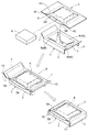
図1、図2は、例えば、オーディオやモニター等の精密機器A(被梱包物の一例)を梱包するのに用いられる梱包具Tを示し、この梱包具Tは、上下一対の同形状の支持枠1と、両支持枠1を収納可能な外箱2と、機器Aを内装可能な内袋3とからなる。
[First Embodiment]
1 and 2 show a packing tool T used for packing precision equipment A (an example of an object to be packed) such as an audio or a monitor, and the packing tool T has a pair of upper and lower same-shaped supports. It consists of a
前記支持枠1は、ダンボール紙等の型紙からなり、矩形状の基部4の表面中央側に機器Aを配置するための矩形状の凹部5を開口形成するとともに、基部4の外周辺部の各々に表面側と裏面側とに折り返し自在なフラップ7を突出形成して構成されている。
The
このフラップ7は、図1、図2に示すように、裏面側に折り返した姿勢において外箱2内で支持枠1の姿勢を保持する脚部として機能する。
As shown in FIGS. 1 and 2, the
この凹部5の縁部に該当する内周辺部の各辺部には、図2に示すように、凹部5内に配置された機器Aを支持する緩衝機能を有した支持片6a〜6d(支持部6の一例)が基端部を支点に折り曲げ自在(詳しくは凹部5の底側に折り込み自在)な状態で突出形成されている。
As shown in FIG. 2, on each side of the inner peripheral portion corresponding to the edge of the
短辺側の支持片6a、6dの突出寸法P1、及び、長辺側の支持片6b、6cの突出寸法P2は、図2に示すように、外箱2内に支持枠1を収納した状態で裏面中央側を向く緩衝機能を有する斜め姿勢となるように、支持枠1のフラップ7の突出寸法(高さ)P7よりも大に設定されている。
The protruding dimension P1 of the short-
下側に位置する支持枠1における支持片6a〜6dの夫々は、機器Aの端部に下方側から当接して受け止め支持するように構成されており、上側に位置する支持枠1における支持片6a〜6dの夫々は、機器Aの端部に上方側から当接して支持するように構成されている。これにより、一対の支持枠1をその表面側どうしが相対向する姿勢で備えることで、下側に位置する支持枠1における支持片6a〜6dと上側に位置する支持枠1における支持片6a〜6dとで上下に挟み込んだ状態で機器Aを支持することができ、しかも、支持片6a〜6dが緩衝機能を有することから、高い緩衝性能を発揮ながら、機器Aを安定して支持することができる。
Each of the
前記外箱2は、ダンボール紙等の型紙からなり、一対の支持枠1の表面どうしが相対向する重合姿勢で一対の支持枠1を収納可能な上方解放型の箱形状に構成されている。
The
この外箱2の上縁部の各辺部には、上面を閉塞可能な折り返し自在な複数のフラップ8(蓋の一例)が突出形成されている。
A plurality of foldable flaps 8 (an example of a lid) that can close the upper surface are formed to protrude from each side of the upper edge of the
外箱2の内部の収納空間S2の横幅W2は、図1、図2に示すように、支持枠1の基部4の横幅W4と同一又はそれよりも僅かに小に構成されているとともに、収納空間S2の縦幅D2は、支持枠1の基部4の縦幅D4と同一又はそれよりも僅かに小に構成されている。
The lateral width W2 of the storage space S2 inside the
また、収納空間S2の高さH2は、表面どうしが相対向する重合姿勢とした一対の支持枠1の高さ(つまり、支持枠1のフラップ7の突出寸法(高さ)P7の2倍の高さ)と同一又はそれよりも僅かに小に構成されている。
In addition, the height H2 of the storage space S2 is twice the height of the pair of support frames 1 in a superposition posture in which the surfaces face each other (that is, twice the protruding dimension (height) P7 of the
前記内袋3は、図3、図4に示すように、伸張変形可能な柔軟な合成樹脂製(樹脂製の一例)のシートからなり、機器Aを内装する状態で支持枠1の一方(一対の支持枠1の一方又は両方の一例)に装着自在で、且つ、その支持枠1に対する装着姿勢で内装された機器Aを支持枠1の凹部5内に位置保持可能に構成されている。なお、前記シートを構成する合成樹脂材としては、ポリプロピレン系の伸び率の高いものを用いている。
As shown in FIGS. 3 and 4, the
この内袋3の長手方向中間部には、長辺側の一方の辺部に挿脱口9を備えた内装空間S3が形成されている。当該内装空間S3は、表裏二枚の樹脂シート(上側被覆部位3Aと下側被覆部位3B)の適所を熱融着することにより構成されている。このようにして、内装空間S3は、上側被覆部位3Aと下側被覆部位3Bの間に形成されている。
An inner space S3 having an insertion /
また、内袋3の裏面側における長手方向両端側には、支持枠1の短辺側の二つのフラップ7(相対向する二つのフラップ7の一例)の夫々に掛止可能な袋状の掛止部10が備えられている。当該掛止部10は、表裏二枚の樹脂シート(上側被覆部位3Aと下側被覆部位3B)の長手方向両端側を折り返したのちに当該折り返し部分の両側を熱融着することにより構成されている。
Further, on both ends in the longitudinal direction on the back surface side of the
この袋状の掛止部10は、内袋3を支持枠1に装着する装着手段、及び、内袋3を支持枠1の短辺側のフラップ7、7に取付ける取付け手段を構成する。
The bag-shaped hooking
図5に示すように、内袋3の横幅(長辺寸法)W3は、支持枠1の基部4の横幅W4に短辺側の二つのフラップ7、7の両突出寸法P7を加算した拡張幅寸法W1と同一又はそれよりも僅かに小に構成されている。
As shown in FIG. 5, the lateral width (long side dimension) W3 of the
つまり、内袋3は、図3に示すように、表面側又は横外側に突出する姿勢のフラップ7、7に対して内袋3の掛止部10を被せて掛止させ、その状態からフラップ7、7を裏面側に折り返すことで、内袋3が短辺側の一対のフラップ7、7に引張される状態で支持枠1に装着されるように構成されている。
That is, as shown in FIG. 3, the
ここで、フラップ7、7に対して内袋3の掛止部10を被せて掛止させることで、支持枠1に対して、上側被覆部位3A及び下側被覆部位3Bが支持枠1の凹部5及びその凹部5の周囲に亘る状態で、内袋3を装着させることができる。そして、フラップ7、7に対して内袋3の掛止部10を被せて掛止させた姿勢は、内袋3の挿入姿勢となっており、この挿入姿勢では、内装空間S3に対する機器Aの挿脱が許容されている。また、フラップ7、7を裏面側に折り返すことで、内袋3が短辺側の一対のフラップ7、7に引張される状態となり、このように、上側被覆部位3A及び下側被覆部位3Bの両者に対して凹部5の周囲側への引張り力が付与されることで、挿入姿勢から装着姿勢に内袋3が姿勢変更されるようになっている。内袋3が装着姿勢に姿勢変更されることで、上側被覆部位3A及び下側被覆部位3Bが一対の支持枠1の夫々における凹部5及びその凹部5の周囲に亘る状態で、一対の支持枠1の夫々における凹部5内に機器Aを位置保持させるようにしている。
Here, the
また、機器Aを内装した状態での内装空間S3の横幅WSは、図5に示すように、凹部5の横幅W5よりも小に設定されていて、図2に示すように、内袋3の内装空間S3の外縁線3aの少なくとも一部が、機器Aを内装して支持枠1に装着された状態で支持枠1の凹部5内に位置するように構成されている。
In addition, the lateral width WS of the interior space S3 in the state in which the device A is interior is set to be smaller than the lateral width W5 of the
なお、内袋3の内装空間S3の外縁線3aの全部が、機器Aを内装して支持枠1に装着された状態で支持枠1の凹部5内に位置するように構成されていてもよい。
In addition, all the
つまり、この梱包具Tは、図2に示すように、内袋3により一対の支持枠1の凹部5内に機器Aを位置保持する状態で、且つ、一対の支持枠1の各支持片6a〜6dで機器Aを緩衝支持する状態で、機器Aを梱包することができる。
That is, as shown in FIG. 2, the packing tool T is in a state in which the device A is positioned and held in the
そのため、落下衝突等の大きな衝撃力が外箱2に作用したときでも、内袋3による位置保持作用(ブレーキ作用)によって機器Aが衝突力の大きな外周側(支持枠1側)に移動するのを抑止することができるとともに、内袋3の伸張変形による緩衝作用と併せて支持部6の変形(湾曲変形又は屈曲変形)による緩衝作用を付与することができ、これらの相乗により、機器Aの故障が極めて生じ難い高い緩衝性能を発揮することができる。
Therefore, even when a large impact force such as a drop collision acts on the
次に、このように構成された梱包具Tの梱包手順を説明する。
図3に示すように、内袋3の挿脱口9を通して内装空間S3に機器Aを収容する。
そして、支持枠1の短辺側の一対のフラップ7、7を表面側(又は横外側)に突出する姿勢にし、それらフラップ7、7に対して内袋3の袋状の掛止部10を被せることで、内袋3の掛止部10とフラップ7とを夫々掛止させる。
Next, the packing procedure of the packing tool T configured as described above will be described.
As shown in FIG. 3, the device A is accommodated in the interior space S <b> 3 through the insertion /
Then, the pair of
その後、支持枠1の短辺側の一対のフラップ7、7を裏面側に折り返すことで、内袋3を短辺側の一対のフラップ7、7に引張される状態で支持枠1に装着する。
Thereafter, the pair of
図1に示すように、内袋3が装着された支持枠1を外箱2の底側に挿入配置するとともに、その上に、表面側が下方を向く姿勢で別の支持枠1を挿入配置し、一対の支持枠1どうしの間に機器Aを挟み込む。
As shown in FIG. 1, the
ここで、内袋3については、図2に示すように、外箱2の底側に挿入配置されて下側に位置する支持枠1に装着されており、その支持枠1の表面側を覆うようにその全体に亘る状態で備えられている。よって、表面側が下方を向く姿勢で別の支持枠1を挿入配置させることで、一対の支持枠1の表面側の夫々によって内袋3が挟み込まれることになり、外箱2に一対の支持枠1を収納させたときに内袋3を引張状態に維持し易いものとなる。
Here, as shown in FIG. 2, the
そして、外箱2の上縁部の各フラップ8を内向きに折り返して上面部を閉塞し、その後、テープ等の固定手段でフラップ8の姿勢を固定することで、機器Aの梱包を完了する。
Then, each
〔第2実施形態〕
上記第1実施形態では、支持枠1を一対備え、それら一対の支持枠1をその表面側どうしが相対向する姿勢で外箱2に収納するようにしている。これに代えて、この第2実施形態では、図6及び図7に示すように、支持枠1を1つ備え、その1つの支持枠1を外箱2に収納するとともに、その支持枠1の上方側の空いた空間に緩衝機能を有する緩衝部材21を配置させるようにしている。
[Second Embodiment]
In the first embodiment, a pair of support frames 1 are provided, and the pair of support frames 1 are stored in the
この第2実施形態では、緩衝部材21が気体封入空間22に気体を封入することで緩衝機能を発揮する袋状の部材にて構成されており、この緩衝部材21が内袋3に一体的に備えられている。例えば、内袋3の上方側被覆部位3Aとなるシートの上側に、更に、気体封入空間形成用シート23を配置し、その上方側被覆部位3Aとなるシートと気体封入空間形成用シート23の所定箇所を一連に熱融着することで、気体封入空間22を形成している。そして、気体封入空間形成用シート23の端部等に備えられた気体供給部(図示は省略)からエア等の気体を気体封入空間22に供給して気体封入空間23に気体を充填させるようにしている。ここで、気体封入空間23については、平面視において、支持枠1の凹部5の全体及びその凹部5の周囲まで亘る状態で形成するのが好ましい。
In this 2nd Embodiment, the
この第2実施形態における梱包手順としては、まずは、上記第1実施形態(図3参照)と同様に、内袋3の挿脱口9を通して内装空間S3に機器Aを収容し、支持枠1の短辺側の一対のフラップ7、7を表面側(又は横外側)に突出する姿勢にし、それらフラップ7、7に対して内袋3の袋状の掛止部10を被せることで、内袋3の掛止部10とフラップ7とを夫々掛止させる。これにより、支持枠1に内袋3を挿入姿勢にて装着している。その後、支持枠1の短辺側の一対のフラップ7、7を裏面側に折り返すことで、内袋3を短辺側の一対のフラップ7、7に引張される状態で支持枠1に装着する。つまり、上側被覆部位3A及び下側被覆部位3Bの両者に対して凹部5の周囲側への引張り力が付与されることで、挿入姿勢から装着姿勢に内袋3が姿勢変更されるようになっている。内袋3が装着姿勢に姿勢変更されることで、上側被覆部位3A及び下側被覆部位3Bが支持枠1の凹部5及びその凹部5の周囲に亘る状態で、支持枠1の凹部5内に機器Aを位置保持させるようにしている。
As a packing procedure in the second embodiment, first, as in the first embodiment (see FIG. 3), the device A is accommodated in the interior space S3 through the insertion /
そして、図6に示すように、内袋3が装着された支持枠1を外箱2の底側に挿入配置し、気体供給部(図示は省略)からエア等の気体を気体封入空間22に供給して、支持枠1の凹部5の全体及びその凹部5の周囲まで亘る状態で形成された気体封入空間22に気体を充填している。これにより、図7に示すように、内袋3に内装された機器Aの上方側及び支持枠1の表面側が気体封入空間22にて覆われることになり、外箱2の上縁部の各フラップ8を内向きに折り返して上面部を閉塞し、その後、テープ等の固定手段でフラップ8の姿勢を固定することで、機器Aの梱包を完了している。
Then, as shown in FIG. 6, the
〔その他の実施形態〕
(1)前述の実施形態では、支持部6を構成するのに、支持枠1の凹部5の縁部から支持片6a〜6dを突出形成する場合を例に示したが、例えば、支持枠1の凹部5の底側にスポンジ等のクッション材を設けるようにしてもよい。
[Other Embodiments]
(1) In the above-mentioned embodiment, although the
(2)前述の実施形態では、内袋3を支持枠1のフラップ7に取付ける取付け手段、及び、機器Aを内装する状態で内袋3を支持枠1に装着する装着手段が、内袋3に袋状の掛止部10から構成されている場合を例に示したが、ホッチキス芯やクリップ等の連結具から構成されていてもよい。
(2) In the above-described embodiment, the attachment means for attaching the
(3)前述の実施形態の変形として、内袋3の挿脱口9を開閉操作するファスナー等の開閉手段が付加的に設けられていてもよい。
(3) As a modification of the above-described embodiment, opening / closing means such as a fastener for opening / closing the insertion /
(4)前述の実施形態では、一対の支持枠1が外箱2とは別部品として構成されている場合を例に示したが、一対の支持枠1の少なくとも一方が外箱2に一体的に備えられていてもよい。
(4) In the above-described embodiment, the case where the pair of support frames 1 is configured as a separate part from the
(5)支持枠1と外箱2の素材は、前述の実施形態で示したが型紙に限らず硬質樹脂や発泡樹脂等の合成樹脂や木や金属等であってもよく、また、内袋3の素材も、前述の実施形態で示した合成樹脂に限らず紙や布等であってもよい。
(5) The material of the
(6)前述の実施形態では、内袋3について、上側被覆部位3Aとなるシートと下側被覆部位3Bとなるシートに対して、相対向する二つの辺部及びその辺部に直交する一つの辺部の合計三つの辺部を熱融着することで、四方のうち、三方が閉塞されて一方が開放された内装空間S3を形成し、開放された一方に挿脱口9を形成している。これに代えて、相対向する二つの辺部のみを熱融着することで、四方のうち、相対向する二方向のみを閉塞して残りの二方向が開放された筒袋状の内装空間を形成するようにしてもよい。
(6) In the above-described embodiment, with respect to the
(7)前述の実施形態では、内袋3の長手方向両端側に掛止部10が備えられ、その掛止部10を支持枠1の短辺側の二つのフラップ7に掛止しているが、逆に、内袋3の短手方向両端部に掛止部を備え、その掛止部を支持枠1の長辺側の二つのフラップに掛止するようにしてもよい。
(7) In the above-described embodiment, the latching
(8)前述の実施形態では、梱包手順として、先に、内袋3の挿脱口9を通して内装空間S3に機器Aを収容しておき、次に、その機器Aが収容された内袋3を支持枠1に装着するようにしている。これに代えて、先に、内装空間S3に機器Aが収容されていない空の内袋3を支持枠1に装着しておき、次に、その支持枠1に装着された内袋3に対して挿脱口9から内装空間S3に機器Aを挿入して収容することもできる。この場合には、フラップ7、7に対して内袋3の袋状の掛止部10を被せることで、内袋3の掛止部10とフラップ7とを夫々掛止させて内袋3を挿入姿勢にて支持枠1に装着することができる。そして、挿入姿勢の内袋3に機器Aを収容させる際には、支持枠1の短辺側の一対のフラップ7、7を表面側(又は横外側)に突出する姿勢にすることで、挿脱口9が大きく開口し易くなり、その収容作業を容易に行うことができる。
(8) In the above-described embodiment, as a packing procedure, the device A is first accommodated in the interior space S3 through the insertion /
(9)前述の実施形態では、一対の支持枠1や1つの支持枠1を収納する対象を外箱2としているが、この外箱2に限らず、支持枠1の周囲を覆う外装体であればよく、この外装体に一対の支持枠1や1つの支持枠1を収納することができる。この場合には、例えば、外装体として緩衝機能を有するものを用いる、或いは、一対の支持枠1や1つの支持枠1の周囲を緩衝材にて覆った状態で外装体に収納させるのが好適である。
(9) In the above-described embodiment, the target for housing the pair of support frames 1 and one
(10)上記第1実施形態では、支持枠1に対して内袋3を装着させるに当たり、下方側に位置する支持枠1に内袋3を装着している。これに代えて、例えば、内袋3の掛止部10の一方を下方側に位置する支持枠1の短辺側のフラップ7に一方に掛止し、内袋3の掛止部10の他方を上方側に位置する支持枠1の短辺側のフラップ7に他方に掛止することで、下方側に位置する支持枠1と上方側に位置する支持枠1とに亘る状態で内袋3を装着することができる。また、内袋3の掛止部10の両方を上方側に位置する支持枠1の短辺側の二つのフラップ7に掛止することで、上方側に位置する支持枠1に内袋3を装着することもできる。
(10) In the first embodiment, when the
(11)上記第2実施形態では、支持枠1の上方側の空いた空間に配置させる緩衝部材21として、気体封入空間形成用シート23にて形成される気体封入空間22に気体を封入することで緩衝機能を発揮する部材にて構成しているが、これに代えて、例えば、スポンジ等の弾性部材を緩衝部材として、内袋3に内装された機器Aの上方側及び支持枠1の表面側を覆うように充填させることもできる。
(11) In the second embodiment, the gas is enclosed in the
本発明は、精密機器に限らず陶器やガラス等の壊れ易い物などの各種物品の運搬に好適に適用することができる。 The present invention can be suitably applied not only to precision instruments but also to transporting various items such as fragile items such as pottery and glass.
1 支持枠
2 外箱(外装体)
3 内袋
3a 外縁線
3A 上側被覆部位
3B 下側被覆部位
5 凹部
6 支持部
6a〜6d 支持片
7 フラップ
10 掛止部(取付け手段)
A 機器(被梱包物)
S3 内装空間
1
DESCRIPTION OF
A Equipment (packaged items)
S3 interior space
Claims (6)
その支持枠を収納可能な外装体と、
上側被覆部位と下側被覆部位とを一体に備え、且つ、上側被覆部位と下側被覆部位との間に内装空間を有する内袋とが備えられ、
前記内袋は、前記上側被覆部位及び前記下側被覆部位が前記支持枠の前記凹部及びその凹部の周囲に亘る状態で、その内装空間に内装された前記被梱包物を前記凹部内に位置保持させる装着姿勢で前記支持枠に装着自在に構成され、
前記支持枠の表面中央側には、前記凹部が形成され、
前記支持枠の外周辺部における相対向する二つの辺部には、表面側と裏面側とに折り返し自在なフラップが形成され、
前記内袋の外周辺部における相対向する二つの辺部と二つの前記フラップとを夫々取付ける取付け手段が備えられ、
前記内袋の前記辺部と前記支持枠の前記フラップの各組について、表面側又は横外側に突出する姿勢の前記フラップに前記内袋の辺部を前記取付け手段で取付けた状態から前記フラップを裏面側に折り返すことで、前記内袋が一対のフラップに引張された前記装着姿勢で支持枠に装着されるように構成されている梱包具。 A support frame having a recess capable of placing an object to be packed;
An exterior body capable of storing the support frame;
An upper covering portion and a lower covering portion are integrally provided, and an inner bag having an interior space between the upper covering portion and the lower covering portion is provided,
The inner bag holds the packaged object, which is housed in the interior space, in the recessed portion with the upper covering portion and the lower covering portion extending around the recessed portion and the recessed portion of the support frame. It is configured to be attachable to the support frame in a mounting posture that allows
The concave portion is formed on the surface center side of the support frame,
Flaps that can be folded back on the front side and the back side are formed on the two opposing sides in the outer peripheral part of the support frame,
There are provided attachment means for attaching the two opposite sides and the two flaps in the outer peripheral part of the inner bag,
For each set of the side portion of the inner bag and the flap of the support frame, the flap is moved from the state in which the side portion of the inner bag is attached to the flap in a posture protruding to the surface side or laterally outer side by the attachment means. A packaging tool configured to be mounted on a support frame in the mounting posture in which the inner bag is pulled by a pair of flaps by folding back to the back surface side .
それら一対の前記支持枠の表面どうしが相対向する姿勢で前記外箱に収納自在に構成され、
前記内袋の装着姿勢は、前記上側被覆部位及び前記下側被覆部位が一対の前記支持枠の夫々における前記凹部及びその凹部の周囲に亘る状態で、一対の前記支持枠の夫々における前記凹部内に前記被梱包物を位置保持させる姿勢に設定されている請求項1〜4のいずれか1項に記載の梱包具。 A pair of the support frames in which the concave portions are arranged on the surface side are provided,
The surfaces of the pair of support frames are configured so as to be freely housed in the outer box in a posture in which the surfaces face each other,
The mounting posture of the inner bag is such that the upper covering portion and the lower covering portion extend in the recesses in each of the pair of support frames, with the recesses in the pair of support frames and the periphery of the recesses. The packing tool according to any one of claims 1 to 4, wherein the packing tool is set to a posture in which the position of the object to be packed is held .
Priority Applications (3)
| Application Number | Priority Date | Filing Date | Title |
|---|---|---|---|
| JP2014100790A JP5952855B2 (en) | 2013-09-03 | 2014-05-14 | Packing tool |
| US14/896,346 US20160297596A1 (en) | 2013-09-03 | 2014-08-20 | Packing tool |
| PCT/JP2014/071763 WO2015033777A1 (en) | 2013-09-03 | 2014-08-20 | Packing tool |
Applications Claiming Priority (3)
| Application Number | Priority Date | Filing Date | Title |
|---|---|---|---|
| JP2013182405 | 2013-09-03 | ||
| JP2013182405 | 2013-09-03 | ||
| JP2014100790A JP5952855B2 (en) | 2013-09-03 | 2014-05-14 | Packing tool |
Related Child Applications (1)
| Application Number | Title | Priority Date | Filing Date |
|---|---|---|---|
| JP2016115827A Division JP6206993B2 (en) | 2013-09-03 | 2016-06-10 | Packing tool |
Publications (3)
| Publication Number | Publication Date |
|---|---|
| JP2015071454A JP2015071454A (en) | 2015-04-16 |
| JP2015071454A5 JP2015071454A5 (en) | 2015-10-29 |
| JP5952855B2 true JP5952855B2 (en) | 2016-07-13 |
Family
ID=52628256
Family Applications (1)
| Application Number | Title | Priority Date | Filing Date |
|---|---|---|---|
| JP2014100790A Active JP5952855B2 (en) | 2013-09-03 | 2014-05-14 | Packing tool |
Country Status (3)
| Country | Link |
|---|---|
| US (1) | US20160297596A1 (en) |
| JP (1) | JP5952855B2 (en) |
| WO (1) | WO2015033777A1 (en) |
Families Citing this family (5)
| Publication number | Priority date | Publication date | Assignee | Title |
|---|---|---|---|---|
| CA2938987C (en) * | 2015-08-18 | 2023-10-17 | Edible Arrangements, Llc | Gift package for sharable apple box |
| JP2017210259A (en) * | 2016-05-25 | 2017-11-30 | 凸版印刷株式会社 | Member for packaging |
| DE102016012963A1 (en) * | 2016-11-01 | 2018-05-03 | Armin König | Packaging process and transport packaging |
| US20180229883A1 (en) * | 2017-02-14 | 2018-08-16 | E - pac Packaging Services Co. Ltd. | Packaging Assembly |
| CN209321455U (en) * | 2018-10-29 | 2019-08-30 | Oppo广东移动通信有限公司 | Pedestal, packing box and device suite |
Family Cites Families (9)
| Publication number | Priority date | Publication date | Assignee | Title |
|---|---|---|---|---|
| US5226542A (en) * | 1990-06-18 | 1993-07-13 | Ade, Inc. | Suspension package |
| DE19725499B4 (en) * | 1997-06-17 | 2005-12-08 | Aesculap Ag & Co. Kg | Packaging unit for sterile items to be packed |
| US5967327A (en) * | 1998-10-02 | 1999-10-19 | Emerging Technologies Trust | Article suspension package, system and method |
| JP4526345B2 (en) * | 2004-09-29 | 2010-08-18 | 京セラミタ株式会社 | Packing box |
| JP4652175B2 (en) * | 2005-08-30 | 2011-03-16 | 京セラミタ株式会社 | Packing box |
| JP5324337B2 (en) * | 2009-06-26 | 2013-10-23 | 日本通運株式会社 | Goods packing device |
| JP2012035856A (en) * | 2010-08-05 | 2012-02-23 | Okamoto Shiko:Kk | Packaging box |
| US8727123B1 (en) * | 2011-03-11 | 2014-05-20 | Larry Roberts | Suspension packaging assembly |
| US9352891B2 (en) * | 2012-12-28 | 2016-05-31 | Ade, Inc. | Suspension packaging structures and methods of making and using the same |
-
2014
- 2014-05-14 JP JP2014100790A patent/JP5952855B2/en active Active
- 2014-08-20 US US14/896,346 patent/US20160297596A1/en not_active Abandoned
- 2014-08-20 WO PCT/JP2014/071763 patent/WO2015033777A1/en active Application Filing
Also Published As
| Publication number | Publication date |
|---|---|
| WO2015033777A1 (en) | 2015-03-12 |
| US20160297596A1 (en) | 2016-10-13 |
| JP2015071454A (en) | 2015-04-16 |
Similar Documents
| Publication | Publication Date | Title |
|---|---|---|
| JP5952855B2 (en) | Packing tool | |
| US8028838B2 (en) | Suspension package assembly | |
| US7296681B2 (en) | Suspension packaging system | |
| US8215488B2 (en) | System and method of packaging | |
| JP5429660B2 (en) | Item packing unit | |
| WO2011043302A1 (en) | Packing mat and packing unit using packing mat | |
| JP6206993B2 (en) | Packing tool | |
| JP3176203U (en) | Packing cushioning material | |
| JP2011025981A (en) | Cushioning-packaging material | |
| JP3101993U (en) | Buffer packaging | |
| JP3733082B2 (en) | Board material carrier | |
| JP2011031891A (en) | Packaging box and loading method | |
| JP2016150779A (en) | Packaging buffer material and packaging box using the same | |
| JP6078603B1 (en) | Packing case | |
| JP5200514B2 (en) | Packaging materials for electronic equipment | |
| JP3060572U (en) | Packaging structure | |
| JPH10278923A (en) | Object holding structure | |
| JP2011037509A (en) | Movement restricting tool, buffering device, and television device equipped with the same | |
| JP2005075388A (en) | Packing container | |
| JP5374988B2 (en) | Unit packing box | |
| JP4913416B2 (en) | Packaging structure | |
| JP2007008482A (en) | Packing device | |
| JP2005247412A (en) | Packing implement | |
| JP2014205501A (en) | Packing box for article transportation | |
| JP2012166822A (en) | Cushioning member |
Legal Events
| Date | Code | Title | Description |
|---|---|---|---|
| A621 | Written request for application examination |
Free format text: JAPANESE INTERMEDIATE CODE: A621 Effective date: 20150708 |
|
| A521 | Request for written amendment filed |
Free format text: JAPANESE INTERMEDIATE CODE: A821 Effective date: 20150708 |
|
| A521 | Request for written amendment filed |
Free format text: JAPANESE INTERMEDIATE CODE: A523 Effective date: 20150810 Free format text: JAPANESE INTERMEDIATE CODE: A523 Effective date: 20150826 |
|
| A871 | Explanation of circumstances concerning accelerated examination |
Free format text: JAPANESE INTERMEDIATE CODE: A871 Effective date: 20150826 |
|
| A975 | Report on accelerated examination |
Free format text: JAPANESE INTERMEDIATE CODE: A971005 Effective date: 20151210 |
|
| A131 | Notification of reasons for refusal |
Free format text: JAPANESE INTERMEDIATE CODE: A131 Effective date: 20151216 |
|
| A521 | Request for written amendment filed |
Free format text: JAPANESE INTERMEDIATE CODE: A523 Effective date: 20160212 |
|
| TRDD | Decision of grant or rejection written | ||
| A01 | Written decision to grant a patent or to grant a registration (utility model) |
Free format text: JAPANESE INTERMEDIATE CODE: A01 Effective date: 20160511 |
|
| A61 | First payment of annual fees (during grant procedure) |
Free format text: JAPANESE INTERMEDIATE CODE: A61 Effective date: 20160610 |
|
| R150 | Certificate of patent or registration of utility model |
Ref document number: 5952855 Country of ref document: JP Free format text: JAPANESE INTERMEDIATE CODE: R150 |
|
| R250 | Receipt of annual fees |
Free format text: JAPANESE INTERMEDIATE CODE: R250 |
|
| R250 | Receipt of annual fees |
Free format text: JAPANESE INTERMEDIATE CODE: R250 |
|
| R250 | Receipt of annual fees |
Free format text: JAPANESE INTERMEDIATE CODE: R250 |
|
| R250 | Receipt of annual fees |
Free format text: JAPANESE INTERMEDIATE CODE: R250 |
|
| R250 | Receipt of annual fees |
Free format text: JAPANESE INTERMEDIATE CODE: R250 |
|
| R250 | Receipt of annual fees |
Free format text: JAPANESE INTERMEDIATE CODE: R250 |