JP5951981B2 - Reinforcing bar crossing fastener - Google Patents
Reinforcing bar crossing fastener Download PDFInfo
- Publication number
- JP5951981B2 JP5951981B2 JP2011282854A JP2011282854A JP5951981B2 JP 5951981 B2 JP5951981 B2 JP 5951981B2 JP 2011282854 A JP2011282854 A JP 2011282854A JP 2011282854 A JP2011282854 A JP 2011282854A JP 5951981 B2 JP5951981 B2 JP 5951981B2
- Authority
- JP
- Japan
- Prior art keywords
- reinforcing bar
- bolt
- bent portion
- shaped
- shaped bent
- Prior art date
- Legal status (The legal status is an assumption and is not a legal conclusion. Google has not performed a legal analysis and makes no representation as to the accuracy of the status listed.)
- Active
Links
Images


Landscapes
- Reinforcement Elements For Buildings (AREA)
Description
本発明は、主に高負荷が掛かる鉄筋交差部を強固に締結固定する鉄筋交差部締結具に関する。 The present invention relates to a reinforcing bar crossing fastener that firmly fastens and fixes a reinforcing bar crossing mainly subjected to a high load.
従来、鉄筋交差部を固定する締結具としては、第1鉄筋と第2鉄筋の交差部を強固に締結固定する高負荷用鉄筋交差部締結具であって、1本のUボルト及び2個のナットと締結プレートとで構成され、
該締結プレートは、前記Uボルトの両端雄ねじ部を挿通可能な挿通孔が形成され、
前記Uボルトは、その両端雄ねじ部とU字状折曲部との間に該U字状折曲部の折曲方向とは略直交する方向へ折曲可能な肉薄板状部が形成されていることを特徴とする高負荷用鉄筋交差部締結具が知られている(例えば、特許文献1参照。)・・・従来例。
Conventionally, as a fastener for fixing a reinforcing bar intersection, it is a high load reinforcing bar crossing fastener that firmly fixes and fixes the intersection of a first reinforcing bar and a second reinforcing bar, and includes one U-bolt and two It consists of a nut and a fastening plate,
The fastening plate is formed with an insertion hole through which both ends of the U bolt can be inserted.
The U-bolt has a thin plate-like portion that can be bent in a direction substantially perpendicular to the bending direction of the U-shaped bent portion between the male screw portions at both ends and the U-shaped bent portion. There is known a high load reinforcing bar crossing portion fastener characterized by being (for example, refer to Patent Document 1).
この従来例によれば、以下に列挙する効果が得られる。
すなわち、従来例では、Uボルトは、その両端雄ねじ部とU字状折曲部との間に該U字状折曲部の折曲方向とは略直交する方向へ折曲可能な肉薄板状部が形成されている構成としたことで、まず、交差された上方の第2鉄筋に対しUボルトのU字状折曲部を上方から係合させた状態で、両肉薄板状部を下方の第1鉄筋の下面に沿ってU字状に折曲させることにより、両雄ねじ部を第2鉄筋の上方へ突出させた状態とし、次に、両雄ねじ部を締結プレートの両挿通孔に挿通してそれぞれナットで締結することにより、第1鉄筋の下面に係合する両肉薄板状部と第2鉄筋の上面に係合するUボルトのU字状折曲部と締結プレートとの間に挟持される状態で第1鉄筋と第2鉄筋の交差部を強固に締結固定することができる。
According to this conventional example, the effects listed below can be obtained.
That is, in the conventional example, the U-bolt is a thin plate that can be bent in a direction substantially perpendicular to the bending direction of the U-shaped bent portion between the male screw portions at both ends and the U-shaped bent portion. First, with the U-shaped bent portion of the U-bolt engaged from above with the intersecting upper second rebar, the two thin plate-like portions are moved downward. By bending the U-shaped portion along the lower surface of the first reinforcing bar, both male threaded portions protrude upward from the second reinforcing bar, and then both male threaded portions are inserted into both insertion holes of the fastening plate. Then, by fastening each with a nut, between the two thin plate-like portions that engage with the lower surface of the first reinforcing bar and the U-shaped bent portion of the U-bolt that engages with the upper surface of the second reinforcing bar, and the fastening plate The crossing portion of the first reinforcing bar and the second reinforcing bar can be firmly fastened and fixed in the sandwiched state.
また、UボルトにおけるU字状折曲部における円弧の直径以下であれば、直径の異なる複数種類の鉄筋の固定が可能であるため、コストダウンが可能になる。 Moreover, if it is below the diameter of the circular arc in the U-shaped bending part in a U volt | bolt, since several types of reinforcing bars from which a diameter differs can be fixed, cost reduction will be attained.
しかしながら、上述の従来例では、Uボルトにおける両端雄ねじ部とU字状折曲部との間に該U字状折曲部の折曲方向とは略直交する方向へ折曲可能な肉薄板状部を形成するために、丸棒の途中を2箇所潰して平らにする工程が必要であり、さらに肉薄板上部を曲げやすくするために焼き鈍し工程が必要であり、従って、製造コストが高くつくという問題点があった。 However, in the above-described conventional example, a thin plate shape that can be bent in a direction substantially orthogonal to the bending direction of the U-shaped bent portion between the both-end male screw portion and the U-shaped bent portion of the U bolt. In order to form the portion, it is necessary to flatten the middle part of the round bar by two places, and further, an annealing step is required to make the upper part of the thin plate easier to bend, and therefore the manufacturing cost is high. There was a problem.
本発明の解決しようとする課題は、従来例に比べ、製造コストの低減が可能であり、かつ、鉄筋交差部への取り付けが容易であると共に、第1鉄筋と第2鉄筋との交差部の強固な締結の他に、場所打ちコンクリート抗(建設・工事現場において、所定の場所を掘削して、その中に打ち込む鉄筋コンクリート製の抗)に用いる鉄筋かごの組み付け工程において、組立用鉄筋リングと主筋との交差部の強固な締結はもちろん、組立用鉄筋リング及びその外周面に沿って溶接固定される組立用帯板リングと、その外面に交差状態で組み付け固定される主筋との交差部の強固な締結が可能な鉄筋交差部締結具を提供することにある。 The problem to be solved by the present invention is that the manufacturing cost can be reduced as compared with the conventional example, the attachment to the reinforcing bar intersection is easy, and the intersection of the first reinforcing bar and the second reinforcing bar In addition to strong fastening, in the assembling process of reinforcing steel cage used for cast-in-place concrete resistance (reinforced concrete resistance that is excavated in a predetermined place at construction sites) As well as a strong fastening at the intersection with the reinforcing bar, the intersection between the reinforcing bar ring for assembly and the belt strip for assembly fixed by welding along its outer peripheral surface and the main reinforcing bar assembled and fixed to the outer surface in a crossed state An object of the present invention is to provide a reinforcing bar crossing fastener that can be fastened.
上記課題を解決するため請求項1記載の鉄筋交差部締結具は、
両端に雄ねじ部を有する1本のUボルト及びナットと締結プレートとで構成され、
前記Uボルトは、その両雄ねじ部とU字状折曲部との間に該U字状折曲部の折曲方向とは交差する方向へ円弧状折曲部を中心として略V字状に折曲形成され、
前記締結プレートには前記Uボルトの両雄ねじ部を挿通可能な挿通孔が形成され、
前記締結プレートは、断面略コ字状に形成され、その両側板部の中央部には主筋に係合する円弧状切欠部が形成されていることを特徴とする手段とした。
In order to solve the above-mentioned problem, the reinforcing bar crossing fastener according to
Consists of one U-bolt and nut having a male thread at both ends, and a fastening plate,
The U-bolt is substantially V-shaped centered on the arc-shaped bent portion in a direction intersecting with the bending direction of the U-shaped bent portion between both male screw portions and the U-shaped bent portion. Bend formation,
The fastening plate is formed with an insertion hole through which both male screw parts of the U bolt can be inserted ,
The fastening plate is formed in a substantially U-shaped cross section, and an arc-shaped notch that engages with the main bar is formed at the center of both side plate portions .
請求項2記載の鉄筋交差部締結具は、請求項1記載の高負荷用鉄筋交差部締結具において、
前記挿通孔の少なくとも一方が長手方向に長い長孔に形成されていることを特徴とする手段とした。
The reinforcing bar crossing part fastener according to
At least one of the insertion holes is formed as a long hole that is long in the longitudinal direction.
請求項3記載の鉄筋交差部締結具は、請求項1又は2に記載の高負荷用鉄筋交差部締結具において、
前記Uボルトにおける略V字状折曲部の開き角度が30°〜40°であることを特徴とする手段とした。
Rebar intersection fastener according to
The opening angle of the substantially V-shaped bent portion of the U-bolt is 30 ° to 40 °.
請求項1記載の鉄筋交差部締結具では、上述のように、Uボルトは、その両雄ねじ部とU字状折曲部との間に該U字状折曲部の折曲方向とは交差する方向へ円弧状折曲部を中心として略V字状に折曲形成されることで、従来例のようにU字状折曲部の折曲方向とは略直交する方向へ折曲可能な肉薄板状部を形成するために丸棒の途中を2箇所潰して平らにする工程を要することなしに、締結部へのUボルトの装着が容易であり、かつ、交差部を強固に締結固定することが可能になる。
従って、製造コストの低減化が可能になる。
In the reinforcing bar intersection fastener according to
Therefore, the manufacturing cost can be reduced.
また、円弧状折曲部を中心として略V字状に折曲形成されることで、主筋と組立用鉄筋リングとの間に組立用鉄筋リングの直径より巾の広い部分、すなわち組立用鉄筋リング介装可能部分が形成されるため、組立用鉄筋リングと主筋との交差部の強固な締結はもちろん、組立用鉄筋リング及びその外周面に沿って溶接固定される組立用帯板リングと、その外面に交差状態で組み付け固定される主筋との交差部へのUボルトの装着が可能かつ容易であると共に、該交差部の強固な締結が可能になる。
また、締結プレートは、断面略コ字状に形成され、その両側板部の中央部には主筋に係合する円弧状切欠部が形成されている構成としたため、両雄ねじ部に対しナットを強く増し締めして行くと、締結プレートに主筋を中心とする曲げ応力が作用するが、円弧状切欠部の開口端面が主筋に当接することで締結プレートの曲がりが停止される。
従って、強固な締結が可能になる。
Further, by being bent in a substantially V shape with the arcuate bent portion as the center, a portion wider than the diameter of the rebar ring for assembly between the main bar and the rebar for assembly, that is, the rebar ring for assembly Since the interposable part is formed, not only the fastening of the intersection of the reinforcing bar for assembly and the main reinforcing bar but also the reinforcing bar ring for assembly and the belt band for assembly fixed by welding along the outer peripheral surface thereof, It is possible and easy to attach the U-bolt to the intersection with the main bar that is assembled and fixed to the outer surface in an intersecting state, and the intersection can be firmly fastened.
In addition, the fastening plate is formed in a substantially U-shaped cross section, and an arc-shaped notch that engages with the main bar is formed in the center of both side plate parts. As the tightening is further performed, bending stress about the main bar acts on the fastening plate, but the bending of the fastening plate is stopped by the opening end surface of the arcuate notch contacting the main bar.
Therefore, firm fastening is possible.
請求項2記載の鉄筋交差部締結具では、上述のように、挿通孔の少なくとも一方が長手方向に長い長孔に形成されることで、両雄ねじ部への締結プレートの装着作業が容易に行えるようになる。
これにより、作業能率を高めることができる。
In the reinforcing bar intersection fastener according to
Thereby, work efficiency can be raised.
請求項3記載の高負荷用鉄筋交差部締結具では、上述のように、Uボルトにおける略V字状折曲部の開き角度が30°〜40°とすることで、締結プレートに対するナットの傾斜角度を最小限に抑えつつ、締結部に対するUボルトの装着容易性を確保することが可能になる。
すなわち、略V字状折曲部の開き角度が30°未満であると、締結部へのUボルト装着が困難になり、また、40°以上であると、締結プレートに対するナットの傾斜角度が大きくなりすぎてナットによる締め付けが不完全になりやすく、このため、交差部を強固に締結することが困難になる。
なお、上記角度数値は、実験の結果得られた値である。
In the high load reinforcing bar intersection fastener according to
That is, when the opening angle of the substantially V-shaped bent portion is less than 30 °, it is difficult to attach the U bolt to the fastening portion, and when it is 40 ° or more, the inclination angle of the nut with respect to the fastening plate is large. Therefore, the tightening with the nut tends to be incomplete, which makes it difficult to firmly fasten the intersection.
The numerical value of the angle is a value obtained as a result of the experiment.
以下にこの発明の実施例を図面に基づいて説明する。 Embodiments of the present invention will be described below with reference to the drawings.
なお、この実施例1では、その使用例1として、場所打ちコンクリート抗(建設・工事現場において、所定の場所を掘削して、その中に打ち込む鉄筋コンクリート製の抗)に用いる鉄筋かごの組み付け工程において、組立用鉄筋リング5の接合部B及びその外周面に沿って溶接固定される組立用帯板リング6と、その外面に交差状態で組み付け固定される複数本の主筋4との交差部を締結する場合を例にとって説明する。
In Example 1, as an example 1 of use, in an assembling process of a reinforcing steel cage used for cast-in-place concrete resistance (in a construction / construction site, excavating a predetermined place and driving it into the concrete) Fastening the intersections of the joint strip B of the
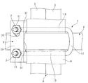
すなわち、この実施例1の高負荷用鉄筋交差部締結具は、略U字状に折曲され、両端に雄ねじ部11、11を有する1本のUボルト1と、雄ねじ部11、11に螺合する2個のナット2と、締結プレート3とで構成されている。
That is, the high load reinforcing bar crossing fastener of the first embodiment is bent into a substantially U shape, and has a
さらに詳述すると、前記Uボルト1は、図1〜3に示すように、鉄等の金属棒状体の両端部に雄ねじ部11、11をねじ切り形成したものを、中央から折曲してU字状折曲部12を形成し、その両雄ねじ部11、11とU字状折曲部12との間に該U字状折曲部12の折曲方向とは交差する方向へ円弧状折曲部13を中心として略V字状に折曲形成された形状となっている。
また、前記Uボルト1における略V字状折曲部の開き角度が30°〜40°に設定されている。
また、前記雄ねじ部11、11は、通常のねじ山に比べ、ねじ山が大きく丸ねじに形成されると共に、ピッチが通常ピッチのより長く形成されている。
More specifically, as shown in FIGS. 1 to 3, the
Moreover, the opening angle of the substantially V-shaped bent part in the U-bolt 1 is set to 30 ° to 40 °.
Further, the
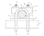
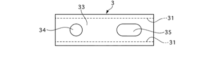
前記締結プレート3は、図4〜6に示すように、鉄等の金属板状体で断面略コ字状に形成され、その両側板部31、31の中央部には主筋4に係合する円弧状切欠部32、32が形成されている。
また、締結プレート3の天板部33には、Uボルトの両雄ねじ部11、11を挿通可能な挿通孔34、35が形成されており、その少なくとも一方の挿通孔35が長手方向に長い長孔に形成されている。
As shown in FIGS. 4 to 6, the
Further, the
次に、実施例1の作用を説明する。
この実施例の鉄筋交差部締結具では、上述のように構成されるため、交差部の締結は、まず、Uボルト1のU字状折曲部12を主筋4に係合させた状態で、該係合部を中心として両雄ねじ部11、11側を組立用鉄筋リング5の下方をくぐるように回転させることにより、組立用鉄筋リング5の下面に円弧状折曲部13を係合させる。
次に、主筋4から上方に突出した両雄ねじ部11、1を締結プレート3の両挿通孔34、35に差し込み、両雄ねじ部11、11にナット2を螺合して締め付けて行くことにより、締結プレート3における両側板部31、31に形成された円弧状切欠部32、32が主筋4の上面に当接する。そして、この状態からナット2、2を増し締めして行くと、締結プレート3に主筋4を中心とする曲げ応力が作用するが、円弧状切欠部32、32の開口端面が主筋4に当接することで締結プレートの曲がりが停止され、これにより、交差部の強固な締結が行われる。
Next, the operation of the first embodiment will be described.
In the reinforcing bar intersection fastener of this embodiment, since it is configured as described above, the fastening of the intersection is first performed with the U-shaped
Next, by inserting both
次に、他の使用例について説明する。この他の使用例の説明にあたっては、前記使用例1と同様の構成部分については図示を省略し、もしくは同一の符号を付けてその説明を省略し、相違点についてのみ説明する。 Next, another usage example will be described. In the description of the other usage examples, the components similar to those of the usage example 1 are not shown, or the same reference numerals are given and the description thereof is omitted, and only the differences will be described.
まず、この発明の使用例2を図7に基づいて説明する。
すなわち、この使用例2は、場所打ちコンクリート抗(建設・工事現場において、所定の場所を掘削して、その中に打ち込む鉄筋コンクリート製の抗)に用いる鉄筋かごの組み付け工程において、組立用鉄筋リング5の接合部及びその外周面に沿って溶接固定される組立用帯板リング6の接合部Cと、その外面に交差状態で組み付け固定される複数本の主筋4との交差部を締結するようにした点が、上記使用例1とは相違したものである。
従って、この使用例2においても、上記使用例1と同様の手順で交差部を容易に締結することができる。
First, Usage Example 2 of the present invention will be described with reference to FIG.
That is, this use example 2 is a reinforced
Therefore, also in this usage example 2, the intersection can be easily fastened in the same procedure as in the above usage example 1.
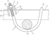
次に、この発明の使用例3を図8に基づいて説明する。
すなわち、この使用例3は、場所打ちコンクリート抗(建設・工事現場において、所定の場所を掘削して、その中に打ち込む鉄筋コンクリート製の抗)に用いる鉄筋かごの組み付け工程において、組立用鉄筋リング5と、その外面に交差状態で組み付け固定される複数本の主筋4との交差部を締結するようにした点が、上記使用例1、2とは相違したものである。
従って、この使用例3においても、上記使用例1と同様の手順で交差部を容易に締結することができる。
Next, Usage Example 3 of the present invention will be described with reference to FIG.
That is, this usage example 3 is a reinforced
Therefore, also in this usage example 3, the intersection can be easily fastened in the same procedure as in the above usage example 1.
次に、本実施例1の効果を説明する。
本実施例1では、上述のように、Uボルト1は、その両雄ねじ部11、11とU字状折曲部12との間に該U字状折曲部12の折曲方向とは交差する方向へ円弧状折曲部13を中心として略V字状に折曲形成されることで、従来例のようにU字状折曲部12の折曲方向とは略直交する方向へ折曲可能な肉薄板状部を形成するために丸棒の途中を2箇所潰して平らにする工程を要することなしに、締結部へのUボルト1の装着が容易であり、かつ、交差部を強固に締結固定することが可能になる。
従って、製造コストの低減化が可能になる。
Next, the effect of the first embodiment will be described.
In the first embodiment, as described above, the
Therefore, the manufacturing cost can be reduced.
また、円弧状折曲部13を中心として略V字状に折曲形成されることで、主筋4と組立用鉄筋リング5との間に組立用鉄筋リング5の直径より巾の広い部分、すなわち組立用鉄筋リング介装可能部分が形成されるため、組立用鉄筋リング5と主筋4との交差部の強固な締結はもちろん、組立用鉄筋リング5及びその外周面に沿って溶接固定される組立用帯板リング6と、その外面に交差状態で組み付け固定される主筋4との交差部へのUボルト1の装着が可能かつ容易であると共に、該交差部の強固な締結が可能になる。
Further, by being bent in a substantially V shape with the arcuate
また、挿通孔34、35の少なくとも一方35が長手方向に長い長孔に形成されることで、両雄ねじ部11、11への締結プレート3の装着作業が容易に行えるようになる。
これにより、作業能率を高めることができる。
In addition, since at least one of the insertion holes 34 and 35 is formed as a long hole that is long in the longitudinal direction, the attaching operation of the
Thereby, work efficiency can be raised.
また、締結プレート3は、断面略コ字状に形成され、その両側板部31、31の中央部には主筋4に係合する円弧状切欠部32が形成されている構成としたため、両雄ねじ部11、11に対しナット2を強く増し締めして行くと、締結プレート3に主筋4を中心とする曲げ応力が作用するが、円弧状切欠部13の開口端面が主筋4に当接することで締結プレート3の曲がりが停止される。
従って、強固な締結が可能になる。
Further, the
Therefore, firm fastening is possible.
また、Uボルト1における略V字状折曲部12の開き角度が30°〜40°とすることで、締結プレー3に対するナッ2の傾斜角度を最小限に抑えつつ、締結部に対するUボルト1の装着容易性を確保することが可能になる。
すなわち、略V字状折曲部12の開き角度が30°未満であると、締結部へのUボルト装着が困難になり、また、40°以上であると、締結プレート3に対するナット2の傾斜角度が大きくなりすぎてナット2による締め付けが不完全になりやすく、このため、交差部を強固に締結することが困難になる。
なお、上記角度数値は、実験の結果得られた値であり、ちなみに、30°がベストであった。
Further, by setting the opening angle of the substantially V-shaped
That is, when the opening angle of the substantially V-shaped
The numerical value of the angle is a value obtained as a result of the experiment, and 30 ° is the best.
また、雄ねじ部11、11は、通常のねじ山に比べ、ねじ山が大きく丸ねじに形成されると共に、ピッチが通常ピッチのより長く形成されることで、雄ねじ部11、11に対するナット2の螺合がスムーズかつ迅速に行なわれる。
従って、現場作業の効率化が図れる。
In addition, the
Therefore, the efficiency of field work can be improved.
以上本実施例を説明してきたが、本発明は上述の実施例に限られるものではなく、本発明の要旨を逸脱しない範囲の設計変更等があっても、本発明に含まれる。 Although the present embodiment has been described above, the present invention is not limited to the above-described embodiment, and design changes and the like within a scope not departing from the gist of the present invention are included in the present invention.
例えば、実施例では、場所打ちコンクリート抗(建設・工事現場において、所定の場所を掘削して、その中に打ち込む鉄筋コンクリート製の抗)に用いる鉄筋かごの組み付け工程において、その交差部を締結する場合を例にとったが、2本以上の鉄筋が交差する全ての交差部の強固な締結が可能である。 For example, in the embodiment, in the process of assembling a reinforcing steel cage used for cast-in-place concrete resistance (in a construction / construction site, excavating a predetermined place and driving into it), the intersection is fastened. However, it is possible to firmly fasten all the intersecting portions where two or more reinforcing bars intersect.
1 Uボルト
11 雄ねじ部
12 U字状折曲部
13 円弧状折曲部
2 ナット
3 締結プレート
31 側板部
32 円弧状切欠部
33 天板部
34 挿通孔
35 挿通孔
4 主筋
5 組立用鉄筋リング
6 組立用帯板リング
DESCRIPTION OF SYMBOLS 1
Claims (3)
前記Uボルトは、その両雄ねじ部とU字状折曲部との間に該U字状折曲部の折曲方向とは交差する方向へ円弧状折曲部を中心として略V字状に折曲形成され、
前記締結プレートには前記Uボルトの両雄ねじ部を挿通可能な挿通孔が形成され、
前記締結プレートは、断面略コ字状に形成され、その両側板部の中央部には主筋に係合する円弧状切欠部が形成されていることを特徴とする鉄筋交差部締結具。 Consists of one U-bolt and nut having a male thread at both ends, and a fastening plate,
The U-bolt is substantially V-shaped centered on the arc-shaped bent portion in a direction intersecting with the bending direction of the U-shaped bent portion between both male screw portions and the U-shaped bent portion. Bend formation,
The fastening plate is formed with an insertion hole through which both male screw parts of the U bolt can be inserted ,
The fastening plate is formed in a substantially U-shaped cross section, and an arc-shaped notch that engages with the main bar is formed at the center of both side plate parts .
前記挿通孔の少なくとも一方が長手方向に長い長孔に形成されていることを特徴とする鉄筋交差部締結具。 In the reinforcing bar crossing fastener according to claim 1,
At least one of the insertion holes is formed as a long hole that is long in the longitudinal direction.
前記Uボルトにおける略V字状折曲部の開き角度が30°〜40°であることを特徴とする鉄筋交差部締結具。 In the reinforcing bar crossing fastener according to claim 1 or 2,
An opening angle of a substantially V-shaped bent portion in the U-bolt is 30 ° to 40 ° .
Priority Applications (1)
| Application Number | Priority Date | Filing Date | Title |
|---|---|---|---|
| JP2011282854A JP5951981B2 (en) | 2011-12-26 | 2011-12-26 | Reinforcing bar crossing fastener |
Applications Claiming Priority (1)
| Application Number | Priority Date | Filing Date | Title |
|---|---|---|---|
| JP2011282854A JP5951981B2 (en) | 2011-12-26 | 2011-12-26 | Reinforcing bar crossing fastener |
Publications (2)
| Publication Number | Publication Date |
|---|---|
| JP2013133595A JP2013133595A (en) | 2013-07-08 |
| JP5951981B2 true JP5951981B2 (en) | 2016-07-13 |
Family
ID=48910485
Family Applications (1)
| Application Number | Title | Priority Date | Filing Date |
|---|---|---|---|
| JP2011282854A Active JP5951981B2 (en) | 2011-12-26 | 2011-12-26 | Reinforcing bar crossing fastener |
Country Status (1)
| Country | Link |
|---|---|
| JP (1) | JP5951981B2 (en) |
Cited By (2)
| Publication number | Priority date | Publication date | Assignee | Title |
|---|---|---|---|---|
| CN107542228A (en) * | 2016-06-28 | 2018-01-05 | 五冶集团上海有限公司 | A kind of regulation snap ring for sliding formwork cover to reinforcement |
| JP6343384B1 (en) * | 2017-12-07 | 2018-06-13 | 新日鉄住金エンジニアリング株式会社 | Rebar fixing tool |
Families Citing this family (3)
| Publication number | Priority date | Publication date | Assignee | Title |
|---|---|---|---|---|
| JP6561470B2 (en) * | 2015-01-14 | 2019-08-21 | ゼン技研株式会社 | Reinforcing bar crossing fastener |
| JP6544514B2 (en) * | 2015-04-20 | 2019-07-17 | ゼン技研株式会社 | Rebar intersection fastener |
| KR102384349B1 (en) * | 2020-09-18 | 2022-04-07 | 주식회사 태광칼륨 | Pipe fixing clamp |
Family Cites Families (2)
| Publication number | Priority date | Publication date | Assignee | Title |
|---|---|---|---|---|
| JPH0637446U (en) * | 1992-10-20 | 1994-05-20 | 松井建設株式会社 | Clip for rebar assembly |
| JP2003184223A (en) * | 2001-12-18 | 2003-07-03 | Taiyo Kiso Kk | Fastener for reinforcements |
-
2011
- 2011-12-26 JP JP2011282854A patent/JP5951981B2/en active Active
Cited By (2)
| Publication number | Priority date | Publication date | Assignee | Title |
|---|---|---|---|---|
| CN107542228A (en) * | 2016-06-28 | 2018-01-05 | 五冶集团上海有限公司 | A kind of regulation snap ring for sliding formwork cover to reinforcement |
| JP6343384B1 (en) * | 2017-12-07 | 2018-06-13 | 新日鉄住金エンジニアリング株式会社 | Rebar fixing tool |
Also Published As
| Publication number | Publication date |
|---|---|
| JP2013133595A (en) | 2013-07-08 |
Similar Documents
| Publication | Publication Date | Title |
|---|---|---|
| JP5951981B2 (en) | Reinforcing bar crossing fastener | |
| JP2018150804A (en) | Pile head joint structure | |
| CN103443504A (en) | Tensioner | |
| JP2014202052A (en) | Reinforcement binding metal fitting for heavy load | |
| JP2009287357A (en) | Joint structure of steel pipes | |
| JP5280228B2 (en) | Reinforcing bar assembly structure | |
| JP4281888B2 (en) | High load rebar clip | |
| JP4659017B2 (en) | Anchor bolt | |
| JP3207104U (en) | Piping support with drop prevention function | |
| KR101773434B1 (en) | Coupling device for concrete and steel File | |
| KR101543961B1 (en) | Complex pile | |
| JP6561470B2 (en) | Reinforcing bar crossing fastener | |
| JP6544514B2 (en) | Rebar intersection fastener | |
| JP5165220B2 (en) | Reinforced concrete structure and method for manufacturing reinforced concrete structure | |
| JP2007092435A (en) | Rebar binding hardware | |
| JP2004003282A (en) | Reinforcement assembled body and metal splicer used therefor | |
| JP4804239B2 (en) | High load rebar crossing fasteners | |
| JP2011058294A (en) | Reinforcement assembling fitting | |
| JP4795836B2 (en) | High load rebar fastener | |
| JP2003147960A (en) | Reinforcement installation type separator bolt and mounting structure of the separator bolt | |
| KR101594728B1 (en) | Complex pile | |
| JP2007291668A (en) | Reinforcement intersection fastener for heavy load | |
| JP7623695B2 (en) | Wire rope fastening fittings | |
| KR200367678Y1 (en) | Reinforcing bar coupler | |
| JP4053961B2 (en) | Structure and method for preventing fall of vertical flaps in formwork |
Legal Events
| Date | Code | Title | Description |
|---|---|---|---|
| A621 | Written request for application examination |
Free format text: JAPANESE INTERMEDIATE CODE: A621 Effective date: 20141222 |
|
| A977 | Report on retrieval |
Free format text: JAPANESE INTERMEDIATE CODE: A971007 Effective date: 20151023 |
|
| A131 | Notification of reasons for refusal |
Free format text: JAPANESE INTERMEDIATE CODE: A131 Effective date: 20151027 |
|
| A521 | Request for written amendment filed |
Free format text: JAPANESE INTERMEDIATE CODE: A523 Effective date: 20151221 |
|
| TRDD | Decision of grant or rejection written | ||
| A01 | Written decision to grant a patent or to grant a registration (utility model) |
Free format text: JAPANESE INTERMEDIATE CODE: A01 Effective date: 20160510 |
|
| A61 | First payment of annual fees (during grant procedure) |
Free format text: JAPANESE INTERMEDIATE CODE: A61 Effective date: 20160609 |
|
| R150 | Certificate of patent or registration of utility model |
Ref document number: 5951981 Country of ref document: JP Free format text: JAPANESE INTERMEDIATE CODE: R150 |
|
| R250 | Receipt of annual fees |
Free format text: JAPANESE INTERMEDIATE CODE: R250 |
|
| R250 | Receipt of annual fees |
Free format text: JAPANESE INTERMEDIATE CODE: R250 |
|
| R250 | Receipt of annual fees |
Free format text: JAPANESE INTERMEDIATE CODE: R250 |
|
| R250 | Receipt of annual fees |
Free format text: JAPANESE INTERMEDIATE CODE: R250 |