JP5948856B2 - Imaging apparatus, autofocus method, and program - Google Patents
Imaging apparatus, autofocus method, and program Download PDFInfo
- Publication number
- JP5948856B2 JP5948856B2 JP2011279579A JP2011279579A JP5948856B2 JP 5948856 B2 JP5948856 B2 JP 5948856B2 JP 2011279579 A JP2011279579 A JP 2011279579A JP 2011279579 A JP2011279579 A JP 2011279579A JP 5948856 B2 JP5948856 B2 JP 5948856B2
- Authority
- JP
- Japan
- Prior art keywords
- image
- captured image
- focus
- subject
- imaging
- Prior art date
- Legal status (The legal status is an assumption and is not a legal conclusion. Google has not performed a legal analysis and makes no representation as to the accuracy of the status listed.)
- Expired - Fee Related
Links
Images


Classifications
-
- H—ELECTRICITY
- H04—ELECTRIC COMMUNICATION TECHNIQUE
- H04N—PICTORIAL COMMUNICATION, e.g. TELEVISION
- H04N13/00—Stereoscopic video systems; Multi-view video systems; Details thereof
- H04N13/20—Image signal generators
- H04N13/204—Image signal generators using stereoscopic image cameras
- H04N13/239—Image signal generators using stereoscopic image cameras using two 2D image sensors having a relative position equal to or related to the interocular distance
-
- G—PHYSICS
- G03—PHOTOGRAPHY; CINEMATOGRAPHY; ANALOGOUS TECHNIQUES USING WAVES OTHER THAN OPTICAL WAVES; ELECTROGRAPHY; HOLOGRAPHY
- G03B—APPARATUS OR ARRANGEMENTS FOR TAKING PHOTOGRAPHS OR FOR PROJECTING OR VIEWING THEM; APPARATUS OR ARRANGEMENTS EMPLOYING ANALOGOUS TECHNIQUES USING WAVES OTHER THAN OPTICAL WAVES; ACCESSORIES THEREFOR
- G03B35/00—Stereoscopic photography
-
- H—ELECTRICITY
- H04—ELECTRIC COMMUNICATION TECHNIQUE
- H04N—PICTORIAL COMMUNICATION, e.g. TELEVISION
- H04N23/00—Cameras or camera modules comprising electronic image sensors; Control thereof
- H04N23/60—Control of cameras or camera modules
- H04N23/67—Focus control based on electronic image sensor signals
- H04N23/673—Focus control based on electronic image sensor signals based on contrast or high frequency components of image signals, e.g. hill climbing method
-
- G—PHYSICS
- G03—PHOTOGRAPHY; CINEMATOGRAPHY; ANALOGOUS TECHNIQUES USING WAVES OTHER THAN OPTICAL WAVES; ELECTROGRAPHY; HOLOGRAPHY
- G03B—APPARATUS OR ARRANGEMENTS FOR TAKING PHOTOGRAPHS OR FOR PROJECTING OR VIEWING THEM; APPARATUS OR ARRANGEMENTS EMPLOYING ANALOGOUS TECHNIQUES USING WAVES OTHER THAN OPTICAL WAVES; ACCESSORIES THEREFOR
- G03B13/00—Viewfinders; Focusing aids for cameras; Means for focusing for cameras; Autofocus systems for cameras
- G03B13/32—Means for focusing
- G03B13/34—Power focusing
- G03B13/36—Autofocus systems
-
- G—PHYSICS
- G03—PHOTOGRAPHY; CINEMATOGRAPHY; ANALOGOUS TECHNIQUES USING WAVES OTHER THAN OPTICAL WAVES; ELECTROGRAPHY; HOLOGRAPHY
- G03B—APPARATUS OR ARRANGEMENTS FOR TAKING PHOTOGRAPHS OR FOR PROJECTING OR VIEWING THEM; APPARATUS OR ARRANGEMENTS EMPLOYING ANALOGOUS TECHNIQUES USING WAVES OTHER THAN OPTICAL WAVES; ACCESSORIES THEREFOR
- G03B3/00—Focusing arrangements of general interest for cameras, projectors or printers
- G03B3/10—Power-operated focusing
-
- H—ELECTRICITY
- H04—ELECTRIC COMMUNICATION TECHNIQUE
- H04N—PICTORIAL COMMUNICATION, e.g. TELEVISION
- H04N13/00—Stereoscopic video systems; Multi-view video systems; Details thereof
- H04N13/20—Image signal generators
- H04N13/296—Synchronisation thereof; Control thereof
Description
この技術は、撮像装置とオートフォーカス方法並びにプログラムに関する。詳しくは、左目用画像を取得するための撮像光学系と右目用画像を取得する撮像光学系のバラツキを吸収して、違和感のない立体画像表示が可能な画像データを生成できるようにする。 This technique relates to an imaging apparatus, an autofocus method, and a program. Specifically, it is possible to generate image data capable of displaying a stereoscopic image without a sense of incongruity by absorbing variations in the imaging optical system for acquiring the left-eye image and the imaging optical system for acquiring the right-eye image.
撮像装置では、自動的に被写体へフォーカスを合わせ続ける機能が従来より設けられている。例えば特許文献1の発明では、撮像画像の画像データからコントラストの高低を判断して合焦位置を決定することが行われている。具体的には、撮像画像の特定領域をフォーカス制御用の信号取得領域(空間周波数抽出エリア)として設定する。この領域は測距枠(検波枠)と呼ばれており、この特定領域のコントラストが高いほどフォーカスが合っており、コントラストが低いとフォーカスがずれていると判定し、コントラストをより高くする位置にレンズを駆動する方式である。またオートフォーカス方式としては、特許文献2に開示されている2画像マッチング方式や特許文献3に開示されている位相差検出方式等も用いられている。
In an imaging apparatus, a function for automatically keeping a focus on a subject is conventionally provided. For example, in the invention of
ところで、左目用画像を取得するための撮像光学系と右目用画像を取得するための撮像光学系を有した撮像装置では、左目用画像と右目用画像を1対として記録する。また、違和感のない立体画像表示を行うために、左目用画像の撮像光学系の合焦位置と右目用画像の撮像光学系の合焦位置が等しくする。例えば、一方の画像の撮像光学系でフォーカス制御を行い、他方の画像の撮像光学系は、一方の画像の撮像光学系の合焦位置に追従させることで合焦位置を等しくする。このようなオートフォーカス制御を行えば、例えばコントラストを利用したフォーカス調整において、視差による左右の画像の違いにより、左右の画像で異なる被写体にピントが合ってしまい、違和感のある立体画像表示となってしまうことを防止できる。しかし、一方の画像の撮像光学系と他方の画像の撮像光学系で特性のバラツキを生じていると、他方の画像の撮像光学系を一方の画像の撮像光学系の合焦位置に追従させた場合、他方の画像でフォーカスがぼけてしまうおそれがある。また、一方の画像と他方の画像の撮像光学系の特性を調整によって揃えるようにした場合、調整に時間を要するため効率よく撮像装置を生産することができない。 By the way, in an imaging apparatus having an imaging optical system for acquiring a left-eye image and an imaging optical system for acquiring a right-eye image, the left-eye image and the right-eye image are recorded as a pair. In addition, in order to perform a stereoscopic image display without a sense of incongruity, the focusing position of the imaging optical system for the left-eye image is made equal to the focusing position of the imaging optical system for the right-eye image. For example, focus control is performed by the imaging optical system of one image, and the imaging optical system of the other image makes the focusing position equal by following the focusing position of the imaging optical system of one image. If such autofocus control is performed, for example, in the focus adjustment using contrast, the left and right images are focused on different subjects due to the difference between the left and right images due to parallax, resulting in an uncomfortable stereoscopic image display. Can be prevented. However, if there is a variation in characteristics between the imaging optical system for one image and the imaging optical system for the other image, the imaging optical system for the other image is made to follow the in-focus position of the imaging optical system for one image. In this case, the focus may be blurred in the other image. In addition, when the characteristics of the imaging optical system of one image and the other image are made uniform by adjustment, it takes time for the adjustment, and the imaging device cannot be produced efficiently.
そこで、この技術では、左目用画像の撮像光学系と右目用画像の撮像光学系のバラツキを吸収して、違和感のない立体画像表示が可能な画像データを生成できるようにした撮像装置とオートフォーカス方法並びにプログラムを提供することを目的とする。 In view of this, in this technique, an imaging apparatus and an autofocus that can generate image data capable of displaying a stereoscopic image without a sense of incongruity by absorbing variations in the imaging optical system for the left-eye image and the imaging optical system for the right-eye image. An object is to provide a method and a program.
この技術の第1の側面は、第1の撮像光学系を介して形成された被写体光学像を電気信号に変換して第1の撮像画像の画像信号を生成する第1の撮像部と、第2の撮像光学系を介して形成された被写体光学像を電気信号に変換して第2の撮像画像の画像信号を生成する第2の撮像部と、前記第1の撮像光学系と前記第2の撮像光学系を独立に制御して、前記第1の撮像画像と前記第2の撮像画像のフォーカス調整を個々に行う制御部とを備え、前記制御部は、前記第1の撮像画像と前記第2の撮像画像の被写体距離とズーム倍率に応じて画角範囲を算出して、前記第1および前記第2の撮像光学系間の基線長と前記画角範囲との比率が閾値以上であり、前記画角範囲が前記基線長に対する前記閾値の範囲以下である場合、前記第1の撮像画像と前記第2の撮像画像のフォーカス調整を個々に行い、前記比率が閾値よりも小さく、前記画角範囲が前記基線長に対する前記閾値の範囲より大きい場合、前記第1の撮像画像の合焦位置に前記第2の撮像画像の合焦位置を追従させる撮像装置にある。 According to a first aspect of the present technology, a first imaging unit that converts a subject optical image formed through the first imaging optical system into an electrical signal and generates an image signal of the first captured image; A second imaging unit that converts a subject optical image formed via the second imaging optical system into an electrical signal to generate an image signal of a second captured image, the first imaging optical system, and the second A control unit that independently controls the imaging optical system and performs focus adjustment on the first captured image and the second captured image individually, and the control unit includes the first captured image and the second captured image. A field angle range is calculated according to the subject distance and zoom magnification of the second captured image, and a ratio between the base line length between the first and second imaging optical systems and the field angle range is equal to or greater than a threshold value. When the field angle range is equal to or smaller than the threshold range with respect to the baseline length, the first captured image When the focus of the second captured image is individually adjusted, and the ratio is smaller than a threshold value and the field angle range is larger than the threshold value range with respect to the baseline length, the focus position of the first captured image is set. In the imaging apparatus that follows the focus position of the second captured image .
この技術においては、第1の撮像光学系を介して形成された被写体光学像が第1の撮像部で電気信号に変換されて第1の撮像画像の画像信号が生成される。また、第2の撮像光学系を介して形成された被写体光学像が第2の撮像部で電気信号に変換されて第2の撮像画像の画像信号が生成される。また、例えば第1の撮像画像と第2の撮像画像の被写体距離が焦点距離に応じた所定距離以上である場合に、第1の撮像光学系と第2の撮像光学系を独立に制御して、第1の撮像画像と第2の撮像画像のフォーカス調整が個々に行われる。フォーカス調整を個々に行う場合、制御部は、一方の撮像画像の合焦位置を基準として他方の撮像画像のフォーカス調整範囲を設定してフォーカス調整を行う。さらに、第1の撮像画像と第2の撮像画像の被写体距離が焦点距離に応じた所定距離以上でない場合には、第2の撮像画像のフォーカス調整を独立した制御から、前記第1の撮像画像のフォーカス調整に追従した制御に切り替えられる。ここで、第2の撮像画像のフォーカス調整を、独立した制御と第1の撮像画像のフォーカス調整に追従した制御との間で切り替える場合、一方の制御の合焦位置から他方の制御の合焦位置に所定速度以下で移動される。 In this technique, the subject optical image formed via the first imaging optical system is converted into an electrical signal by the first imaging unit to generate an image signal of the first captured image. Further, the subject optical image formed via the second imaging optical system is converted into an electrical signal by the second imaging unit, and an image signal of the second captured image is generated. For example, when the subject distance between the first captured image and the second captured image is equal to or greater than a predetermined distance corresponding to the focal length, the first imaging optical system and the second imaging optical system are controlled independently. The focus adjustment of the first captured image and the second captured image is performed individually. When performing the focus adjustment individually, the control unit performs the focus adjustment by setting the focus adjustment range of the other captured image based on the in-focus position of the one captured image. Furthermore, when the subject distance between the first captured image and the second captured image is not equal to or greater than a predetermined distance corresponding to the focal length, the first captured image is controlled from independent control of focus adjustment of the second captured image. The control can be switched to follow the focus adjustment. Here, when the focus adjustment of the second captured image is switched between the independent control and the control following the focus adjustment of the first captured image, the focus of one control is focused from the focus position of one control. It is moved to a position below a predetermined speed.
また、第1の撮像画像の画像信号に基づき被写体認識を行う被写体認識部を備え、制御部は、被写体認識部で認識された所望の被写体にフォーカスを追従させる場合、第1の撮像画像のフォーカス調整に追従した制御が行われる。また、制御部は、第1の撮像画像においてフォーカス調整に用いる第1の検波領域の画像と、第2の撮像画像においてフォーカス調整に用いる第2の検波領域の画像で、被写体範囲が一致するように、焦点距離毎に少なくとも第1の検波領域と前記第2の検波領域の何れかの位置の調節が行われる。 In addition, a subject recognition unit that performs subject recognition based on the image signal of the first captured image is provided, and the control unit focuses the first captured image when the focus follows the desired subject recognized by the subject recognition unit. Control following the adjustment is performed. In addition, the control unit may match the subject range between the image of the first detection area used for focus adjustment in the first captured image and the image of the second detection area used for focus adjustment in the second captured image. In addition, the position of at least one of the first detection area and the second detection area is adjusted for each focal length.
この技術の第2の側面は、第1の撮像光学系を介して形成された被写体光学像を第1の撮像部で電気信号に変換して第1の撮像画像の画像信号を生成する工程と、第2の撮像光学系を介して形成された被写体光学像を第2の撮像部で電気信号に変換して第2の撮像画像の画像信号を生成する工程と、前記第1の撮像画像と前記第2の撮像画像の被写体距離とズーム倍率に応じて画角範囲を算出して、前記第1および前記第2の撮像光学系間の基線長と前記画角範囲との比率が閾値以上であり、前記画角範囲が前記基線長に対する前記閾値の範囲以下である場合、前記第1の撮像画像と前記第2の撮像画像のフォーカス調整を個々に行い、前記比率が閾値よりも小さく、前記画角範囲が前記基線長に対する前記閾値の範囲より大きい場合、前記第1の撮像画像の合焦位置に前記第2の撮像画像の合焦位置を追従させる工程とを含むオートフォーカス方法にある。 According to a second aspect of the present technology, a subject optical image formed via the first imaging optical system is converted into an electrical signal by the first imaging unit to generate an image signal of the first captured image; Converting a subject optical image formed via the second imaging optical system into an electrical signal by the second imaging unit to generate an image signal of the second captured image; and the first captured image; A field angle range is calculated according to the subject distance and zoom magnification of the second captured image, and a ratio between the base line length between the first and second imaging optical systems and the field angle range is equal to or greater than a threshold value. And when the field angle range is equal to or smaller than the threshold range with respect to the baseline length, the first captured image and the second captured image are individually adjusted in focus, and the ratio is smaller than the threshold value. When the angle of view range is larger than the threshold range for the baseline length, In autofocus method comprising the step of tracking the focus position of the second captured image focus position of one of the captured image.
この技術の第3の側面は、第1の撮像光学系を介して形成された被写体光学像を電気信号に変換して生成された第1の撮像画像の画像信号と、第2の撮像光学系を介して形成された被写体光学像を電気信号に変換して生成した第2の撮像画像の画像信号を用いてオートフォーカスの制御をコンピュータで実行させるプログラムであって、前記第1の撮像画像と前記第2の撮像画像の被写体距離とズーム倍率に応じて画角範囲を算出して、前記第1および前記第2の撮像光学系間の基線長と前記画角範囲との比率が閾値以上であり、前記画角範囲が前記基線長に対する前記閾値の範囲以下である場合、前記第1の撮像画像と前記第2の撮像画像のフォーカス調整を個々に行い、前記比率が閾値よりも小さく、前記画角範囲が前記基線長に対する前記閾値の範囲より大きいる場合、前記第1の撮像画像の合焦位置に前記第2の撮像画像の合焦位置を追従させる手順を前記コンピュータで実行させるプログラムにある。 According to a third aspect of the present technology, an image signal of a first captured image generated by converting a subject optical image formed via the first imaging optical system into an electrical signal, and a second imaging optical system a program to be executed by a computer controlling the autofocus by using an image signal of the second captured image of a subject optical image formed was generated by converting an electric signal via, said first captured image A field angle range is calculated according to the subject distance and zoom magnification of the second captured image, and a ratio between the base line length between the first and second imaging optical systems and the field angle range is equal to or greater than a threshold value. And when the field angle range is equal to or smaller than the threshold range with respect to the baseline length, the first captured image and the second captured image are individually adjusted in focus, and the ratio is smaller than the threshold value. The angle of view range is relative to the baseline length. If you are larger than the range of the serial threshold is a procedure to follow the focus position of the second captured image focus position of the first captured image in a program to be executed by the computer.
なお、本技術のプログラムは、例えば、様々なプログラム・コードを実行可能な汎用コンピュータに対して、コンピュータ可読な形式で提供する記憶媒体、通信媒体、例えば、光ディスクや磁気ディスク、半導体メモリなどの記憶媒体、あるいは、ネットワークなどの通信媒体によって提供可能なプログラムである。このようなプログラムをコンピュータ可読な形式で提供することにより、コンピュータ上でプログラムに応じた処理が実現される。 Note that the program of the present technology is, for example, a storage medium or a communication medium provided in a computer-readable format to a general-purpose computer that can execute various program codes, such as an optical disk, a magnetic disk, or a semiconductor memory. It is a program that can be provided by a medium or a communication medium such as a network. By providing such a program in a computer-readable format, processing corresponding to the program is realized on the computer.
この技術によれば、第1の撮像光学系を介して形成された被写体光学像が第1の撮像部で電気信号に変換されて第1の撮像画像の画像信号が生成される。また、第2の撮像光学系を介して形成された被写体光学像が第2の撮像部で電気信号に変換されて第2の撮像画像の画像信号が生成される。さらに、第1の撮像光学系と第2の撮像光学系を独立に制御して、第1の撮像画像と第2の撮像画像のフォーカス調整が個々に行われる。このため、例えば左目用画像を取得するための撮像光学系と右目用画像を取得する撮像光学系でフォーカスの合うレンズ位置がバラツキを生じていても、このバラツキを吸収して、違和感のない立体画像表示が可能な画像データを生成できる。 According to this technique, the subject optical image formed via the first imaging optical system is converted into an electrical signal by the first imaging unit, and an image signal of the first captured image is generated. Further, the subject optical image formed via the second imaging optical system is converted into an electrical signal by the second imaging unit, and an image signal of the second captured image is generated. Further, the first imaging optical system and the second imaging optical system are controlled independently, and the focus adjustment of the first captured image and the second captured image is performed individually. For this reason, for example, even if there is a variation in the lens position that is in focus between the imaging optical system for acquiring the image for the left eye and the imaging optical system for acquiring the image for the right eye, this variation is absorbed, and there is no sense of incongruity. Image data capable of image display can be generated.
以下、本技術を実施するための形態について説明する。なお、説明は以下の順序で行う。
1.第1の実施の形態
2.第2の実施の形態
3.第3の実施の形態
4.第4の実施の形態
Hereinafter, embodiments for carrying out the present technology will be described. The description will be given in the following order.
1. 1. First embodiment 2. Second embodiment 3. Third embodiment Fourth embodiment
<1.第1の実施の形態>
[1−1.第1の実施の形態の構成]
図1は、本技術の撮像装置の構成を例示している。撮像装置10は、左目画像を取得するための左目撮像光学系21L、右目画像を取得するための右目撮像光学系21R、左目撮像光学系駆動部22L、右目撮像光学系駆動部22R、左目画像用撮像部31L、右目画像用撮像部31Rを有している。また、撮像装置10は、信号処理部32、コーデック部33、メディアインタフェース部34、記録メディア35を有している。さらに、撮像装置10は、メモリ部41、操作部42、制御部45を有している。
<1. First Embodiment>
[1-1. Configuration of First Embodiment]
FIG. 1 illustrates the configuration of an imaging apparatus according to the present technology. The
左目撮像光学系21Lと右目撮像光学系21Rは、撮像レンズ群や絞り機構,NDフィルタを挿入するND機構等で構成されている。また、撮像レンズ群は、ズームレンズやフォーカスレンズ、撮像時の手の振動を補正するシフト防振式手振れ補正レンズ等で構成されている。左目撮像光学系21Lは、左目撮像光学系駆動部22Lから供給された駆動信号に基づき撮像レンズ群や絞り機構,ND機構を駆動して、フォーカス動作やズーム動作,手振れ補正動作,光量調整動作等を行う。同様に、右目撮像光学系21Rは、右目撮像光学系駆動部22Rから供給された駆動信号に基づき撮像レンズ群や絞り機構,ND機構等を駆動して、フォーカス動作やズーム動作,手振れ補正動作,光量調整動作等を行う。
The left-eye imaging
左目撮像光学系駆動部22Lは、後述する制御部45からの制御信号に基づいて左目撮像光学系21Lの撮像レンズ群や絞りを駆動するための駆動信号を生成する。左目撮像光学系駆動部22Lは、生成した駆動信号を左目撮像光学系21Lに出力する。
The left-eye imaging optical
右目撮像光学系駆動部22Rは、制御部45からの制御信号に基づいて右目撮像光学系21Rの撮像レンズ群や絞りを駆動するための駆動信号を生成する。右目撮像光学系駆動部22Rは、生成した駆動信号を右目撮像光学系21Rに出力する。
The right-eye imaging optical
左目画像用撮像部31Lは、撮像素子やノイズ除去部,A/D変換器等を用いて構成されている。撮像素子は、CMOS(Complementary Metal Oxide Semiconductor)固体撮像素子やCCD(Charge Coupled Device)固体撮像素子が用いられている。撮像素子は、光電変換を行い、左目撮像光学系21Lによって撮像面に結像された光学像に応じた画像信号を生成する。ノイズ除去部は、撮像素子で生成された画像信号に対して例えば相関二重サンプリング処理等を行い、画像信号からノイズを除去する。また、ノイズ除去部は、ノイズ除去後の画像信号を所望の信号レベルに増幅する。A/D変換器は、ノイズ除去部で処理された画像信号をディジタルの画像信号に変換して信号処理部32に出力する。
The left-eye
右目画像用撮像部31Rは、左目画像用撮像部31Lと同様に構成されており、右目撮像光学系21Rによって撮像素子の撮像面に結像された光学像に応じたディジタルの画像信号を生成して信号処理部32に出力する。
The right-eye
信号処理部32は、ホワイトバランス補正部、ガンマ補正部、輪郭補正部、輝度・色差信号生成部等を有している。信号処理部32は、左目画像用撮像部31Lと右目画像用撮像部31Rから供給された画像信号に対して、制御部45からの制御信号に基づきホワイトバランス調整処理やガンマ補正処理、輪郭補正処理等を行う。また、信号処理部32は、種々の処理が行われた画像信号を、例えば輝度と色差の画像データに変換してコーデック部33に出力する。
The
また、信号処理部32は、画像信号を解析してフォーカスを追従させる被写体の認識を行う被写体認識部を有する構成であってもよい。なお、被写体認識部は、被写体の認識結果を制御部45に出力する。
Further, the
コーデック部33は、左目画像の画像データと右目画像の画像データを用いて、立体画像(三次元画像)としての符号化処理を行い、符号化データをメディアインタフェース部34に出力する。また、コーデック部33は、符号化データの復号処理を行う。
The
メディアインタフェース部34は、記録メディア35に符号化データ等を記録したり、記録メディア35に記録されている符号化データ等を読み出すためのインタフェースである。
The
記録メディア35は、フラッシュメモリやハードディスクなどが用いられる。記録メディア35は、撮像装置10に内蔵されてもよく、着脱可能とされてもよい。なお、記録メディア35としては、光ディスクや光磁気ディスク等の記録メディアを用いるようにしてもよい。
The
メモリ部41は、撮像装置10の動作を制御するためのプログラムや種々のデータ等が記憶される。
The
操作部42は、レリーズスイッチ,ズームボタン,動作の切り替えを行う切り替えボタン、各種の設定を行うための操作ボタン等で構成されている。操作部42は、ユーザ操作に応じた操作信号を生成して制御部45に出力する。
The
制御部45は、メモリ部41に記憶されているプログラムを実行して、メモリ部41に記憶されている種々のデータや操作部42から供給された操作信号に基づき、撮像装置10がユーザ操作に応じた動作となるように制御信号を生成して各部に供給する。
The
また、制御部45は、信号処理部32に供給された画像信号を利用して、被写体にフォーカスを合わせるオートフォーカス制御や、明るさの調節を行うオートアイリス制御などの処理を行う。オートフォーカス制御では、画像信号からオートフォーカス制御に必要な物理量を算出する。例えば画像のコントラストによりオートフォーカス制御を行う場合、画像信号から画像の鮮鋭度を示す焦点評価値を算出する。制御部45は、この焦点評価値が極大となる位置を検出し、その位置にフォーカスレンズを移動させる。すなわち、フォーカスレンズを至近から無限遠まで所定のステップで移動させ、各位置で焦点評価値を取得して、得られた焦点評価値が最大の位置を合焦位置として、その位置にフォーカスレンズを移動させる。さらに、制御部45は、信号処理部32からの被写体認識結果に基づき、オートフォーカス制御動作の切り替えを行うようにしてもよい。
In addition, the
なお、図示せずも、撮像装置10には音声を記録するためのマイクや、カメラスルー画像,記録画像および再生画像等の表示を行う表示部等も設けられる。
Although not shown, the
[1−2.第1の実施の形態の動作]
このように、左目画像を取得するための左目撮像光学系21Lと右目撮像光学系21Rが設けられる場合、左目画像と右目画像は視差を有する。図2は、左目画像と右目画像を例示している。なお、図2では、全体の画像を1枚の立体画像とみなして、左目撮像光学系21Lと左目画像用撮像部31Lによって取得される左目画像と、右目撮像光学系21Rと右目画像用撮像部31Rによって取得される右目画像とを例示している。なお、実線で示す枠は左目画像、二重線で示す枠は右目画像を示している。
[1-2. Operation of First Embodiment]
Thus, when the left eye imaging
また、オートフォーカス制御において、フォーカス調整に用いる画像領域(検波領域)をそれぞれの撮像画像の中央に配置した場合、検波領域の画像は視差を有した画像となる。なお、破線で示す枠は左目画像検波領域、一点鎖線で示す枠は右目画像検波領域を示している。 In addition, in autofocus control, when an image region (detection region) used for focus adjustment is arranged at the center of each captured image, the image in the detection region is an image having parallax. A frame indicated by a broken line indicates a left-eye image detection region, and a frame indicated by an alternate long and short dash line indicates a right-eye image detection region.
図3は、図2における視差を撮像装置10からの視点で示している。撮像装置10における左目画像と右目画像は、光軸に対して左右の画角が同一になるように調整されているものとする。また、基線長すなわち左目撮像光学系の光軸と、右目撮像光学系の光軸との間隔は固定である。基線長は、撮像装置10において固定値であることから、被写体距離が長くなればなるほど、被写体距離に対する基線長の比率は小さくなる。すなわち、比率が小さくなると視差による左目画像と右目画像の相違が少なくなり、比率が大きくなると視差による左目画像と右目画像の相違が顕著となる。
FIG. 3 shows the parallax in FIG. 2 from the viewpoint of the
また、ズーム動作を行う場合、ズームレンズの位置が望遠側となると被写体が拡大されて表示されることから、ズーム倍率が高い場合には視差による左目画像と右目画像の相違が顕著となる。また、ズーム倍率が低い場合は、視差による左目画像と右目画像の相違が少なくなる。すなわち、焦点距離に応じて視差による左目画像と右目画像の相違が変化する。 Further, when performing a zoom operation, the subject is enlarged and displayed when the zoom lens is positioned on the telephoto side, so that when the zoom magnification is high, the difference between the left eye image and the right eye image due to parallax becomes significant. Further, when the zoom magnification is low, the difference between the left-eye image and the right-eye image due to parallax is reduced. That is, the difference between the left-eye image and the right-eye image due to parallax changes according to the focal length.
さらに、被写体距離に対する基線長の比率が大きい場合に、左目画像と右目画像で独立してオートフォーカス制御を行った場合、左目画像と右目画像では異なる被写体にピントがあってしまうおそれがある。例えば近接した被写体と離れた被写体が撮像画角内に混在している場合、左目画像の検波領域の画像が主に近接した被写体の画像であると、近接した被写体に対して合焦するようにオートフォーカス制御動作が行われる。また、右目画像の検波領域の画像が主に離れた被写体の画像であると、離れた被写体に対して合焦するようにオートフォーカス制御動作が行われる。したがって、左目画像は近接した被写体にピントが合った画像となり、右目画像は離れた被写体にピントが合った画像となってしまうおそれがある。 Furthermore, when the ratio of the base line length to the subject distance is large and auto focus control is performed independently for the left eye image and the right eye image, there is a possibility that different subjects may be in focus in the left eye image and the right eye image. For example, when a close subject and a distant subject are mixed within the imaging angle of view, if the image in the detection region of the left-eye image is mainly an image of a close subject, the close subject is focused. Autofocus control operation is performed. In addition, when the image in the detection region of the right-eye image is an image of a subject that is mainly away, an autofocus control operation is performed so that the distant subject is focused. Therefore, the left eye image may be an image focused on a close subject, and the right eye image may be an image focused on a distant subject.
そこで、撮像装置10は、視差による左目画像と右目画像の相違が顕著となる場合、すなわち被写体距離が焦点距離に応じた所定距離以上でない場合、それぞれの画像が所望の被写体にピントが合った画像となるように、左目画像と右目画像で独立してオートフォーカス制御動作を行う。また、視差による左目画像と右目画像の相違が少ない場合、すなわち被写体距離が焦点距離に応じた所定距離以上である場合、左目画像と右目画像で異なる被写体にピントが合った画像とならないように、一方の画像についてはオートフォーカス制御動作を行い、他方の画像の合焦位置は一方の画像の合焦位置に追従させる。
Therefore, when the difference between the left-eye image and the right-eye image due to parallax becomes significant , that is, when the subject distance is not equal to or greater than a predetermined distance corresponding to the focal length, each image is in focus on the desired subject. Thus, the autofocus control operation is performed independently for the left eye image and the right eye image. In addition, when there is little difference between the left eye image and the right eye image due to parallax, that is, when the subject distance is equal to or greater than a predetermined distance according to the focal length, the left eye image and the right eye image are not focused on different subjects. An autofocus control operation is performed for one image, and the focus position of the other image is made to follow the focus position of one image.
なお、被写体距離は、測距手段によって測定してもよく、合焦状態におけるフォーカスレンズとズームレンズの位置から推定してもよい。 Note that the subject distance may be measured by distance measuring means, or may be estimated from the positions of the focus lens and the zoom lens in the focused state.
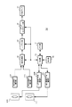
図4は、フォーカスレンズとズームレンズの位置から被写体距離を推定する動作を説明するための図である。なお、図4では、撮像装置10の撮像光学系におけるズームレンズの移動可動範囲とフォーカスレンズの移動可能範囲とからなる位置空間における動作領域を示している。
FIG. 4 is a diagram for explaining the operation of estimating the subject distance from the positions of the focus lens and the zoom lens. FIG. 4 shows an operation region in a position space including a movable movable range of the zoom lens and a movable movable range of the focus lens in the imaging optical system of the
位置空間は、ズームレンズの物理的な移動可能範囲を横軸にとり、左方向(減少方向)が広角(Wide)側、右方向(増加方向)が望遠(Tele)側に設定されている。また、フォーカスレンズの物理的な移動可能範囲を縦軸にとり、下方向(減少方向)が遠距離(Far)側、上方向(増加方向)が近距離(near)側に設定されている。 In the position space, the horizontal movable axis of the zoom lens is set on the horizontal axis, and the left direction (decreasing direction) is set to the wide angle (Wide) side, and the right direction (increasing direction) is set to the telephoto side (Tele) side. In addition, the physical movable range of the focus lens is set on the vertical axis, and the downward direction (decreasing direction) is set to the far distance (Far) side, and the upward direction (increasing direction) is set to the near distance (near) side.
曲線L1は、無限遠の被写体に合焦するズームレンズ位置とフォーカスレンズ位置の組み合わせの軌跡を示している。曲線L2は、最短撮像距離の被写体に合焦するズームレンズ位置とフォーカスレンズ位置の組み合わせの軌跡を示している。なお、曲線L3は、ズームの全動作領域において合焦可能な最短の撮像距離についてのズームレンズ位置とフォーカスレンズ位置の組み合わせの軌跡を示している。 A curve L1 indicates a locus of a combination of a zoom lens position and a focus lens position that focuses on a subject at infinity. A curved line L2 indicates a locus of a combination of the zoom lens position and the focus lens position that focuses on the subject with the shortest imaging distance. A curve L3 indicates a locus of a combination of the zoom lens position and the focus lens position for the shortest imaging distance that can be focused in the entire zoom operation region.
通常動作領域(斜線で示す領域)は、曲線L1,L2,L3、およびフォーカスレンズのマクロ至近端によって囲まれた領域であり、通常モードの動作においては、この領域内でのみ、ズームレンズ位置とフォーカスレンズ位置の調整が可能である。なお、インナーフォーカス方式である撮像装置の場合、マクロモードの動作の領域(クロスハッチングで示す領域)が、図示するようにTele端側に設けられる。 The normal operation area (area shown by oblique lines) is an area surrounded by the curves L1, L2, L3 and the macro close end of the focus lens. In normal mode operation, the zoom lens position is only within this area. And the focus lens position can be adjusted. Note that, in the case of an imaging apparatus that uses the inner focus method, an area for macro mode operation (area indicated by cross-hatching) is provided on the Tele end side as illustrated.
ここで、例えば合焦状態となったときのズームレンズ位置を「PZa」、フォーカスレンズの位置を「PFa」とする。この場合、ズームレンズ位置が「PZa」でフォーカスレンズの位置が「PFa」である点を通過する軌跡Laに対応する撮像距離を被写体距離Maと推定する。 Here, for example, it is assumed that the zoom lens position in the in-focus state is “PZa” and the focus lens position is “PFa”. In this case, the imaging distance corresponding to the locus La passing through the point where the zoom lens position is “PZa” and the focus lens position is “PFa” is estimated as the subject distance Ma.
図5は、制御部45のオートフォーカス制御動作を示すフローチャートである。ステップST1で制御部45は、検波対象が動体でないか判別する。制御部45は信号処理部32から供給された被写体認識結果に基づき、検波領域の被写体が動体でないか判別する。制御部45は、検波領域の被写体が動体でない場合にステップST2に進み、検波領域の被写体が動体である場合にステップST5に進む。
FIG. 5 is a flowchart showing the autofocus control operation of the
ステップST2で制御部45は、被写体距離を判別する。制御部45は、例えば上述のようにフォーカスレンズの位置とズームレンズの位置から被写体距離Maを推定してステップST3に進む。
In step ST2, the
ステップST3で制御部45は、画角範囲を算出する。制御部45は、図6に示すように画角2θと被写体距離Maから撮像光学系の画角範囲Mwを式(1)に基づいて算出する。なお、画角2θは、焦点距離に応じたレンズ固有の値であり、ズーム倍率に応じて変化する。
Mw=tanθ×Ma×2 ・・・(1)
In step ST3, the
Mw = tan θ × Ma × 2 (1)
ステップST4で制御部45は、フォーカス制御判別値が閾値以上であるか判定する。制御部45は画角範囲Mwと基線長Mrの比率を式(2)に基づき算出して、フォーカス制御判別値Qmとする。制御部45はフォーカス制御判別値Qmが閾値以上である場合はステップST5に進み、閾値よりも小さい場合はステップST6に進む。
Qm=Mr/Mw ・・・(2)
In step ST4, the
Qm = Mr / Mw (2)
ステップST5で制御部45は、追従動作を行う。制御部45は、基線長に対して画角範囲が大きくない場合、左目画像と右目画像は視差による画像の相違が顕著となることから、一方の画像についてオートフォーカス制御動作を行い、他方の画像の合焦位置を一方の画像の合焦位置に追従させる。また、制御部45は、検波対象を動体とした場合、動体に正しくピントを合わせるため総じて検波領域が小さく設定される。このように検波領域を小さく設定すると視差による画像の相違を無視できない。また、動体であるため例えば画面の端に被写体が動いた場合、一方のレンズではその被写体を捉えられないおそれがある。したがって、このような場合にも、一方の画像についてオートフォーカス制御動作を行い、他方の画像の合焦位置を一方の画像の合焦位置に追従させる。制御部45は、このように独立動作を行いステップST1に戻る。
In step ST5, the
ステップST6で制御部45は、独立動作を行う。制御部45は、基線長に対して画角範囲が大きく、左目画像と右目画像は視差による画像の相違が少ないことから、左目画像と右目画像のそれぞれで独立してオートフォーカス動作を行いステップST1に戻る。
In step ST6, the
このようなオートフォーカス制御動作を撮像装置10で行えば、撮像装置10で生成される左目画像と右目画像の画像信号は、合焦位置が大きく異なり違和感のある画像となってしまうことを防止できる。なお、オートフォーカス方式は、コントラスト方式に限られない。例えば2画像マッチング方式や位相差検出方式などでもよい。
If such an autofocus control operation is performed by the
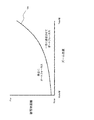
ところで、焦点距離は上述のようにズーム倍率によって変化する。例えばTele側にズーミングするにしたがって、光学的な画角は狭くなり、同一被写体距離における画面全体に対する視差の割合は大きくなる。したがって、制御部45は、被写体距離と焦点距離(ズーレンズの位置に相当)に応じた所定距離の比較結果に基づきオートフォーカス制御動作の設定を行うようにしてもよい。
Incidentally, the focal length varies depending on the zoom magnification as described above. For example, as the zooming is performed toward the Tele side, the optical angle of view becomes narrower, and the ratio of parallax to the entire screen at the same subject distance increases. Therefore, the
図7は、被写体距離とズームレンズの位置に応じて設定されるオートフォーカス制御動作を説明するための図である。例えば、図7に示すように閾値THを設定して、ズームレンズ位置と被写体距離で示される点が閾値上または閾値よりも上側である領域の場合、
すなわち被写体距離が焦点距離に応じた所定距離以上である場合、左目画像と右目画像のそれぞれで独立してオートフォーカス制御動作を行う。また、閾値よりも下側である領域の場合、すなわち被写体距離が焦点距離に応じた所定距離以上でない場合には、一方の画像についてオートフォーカス制御動作を行い、他方の画像の合焦位置を一方の画像の合焦位置に追従させる。このようにすれば、被写体距離とズームレンズの位置に応じて、違和感のない立体画像表示を行うことができるようにオートフォーカス制御動作を設定できる。なお、閾値を示すカーブのデータは、撮像光学系に応じて一意に決定されることから、このデータを予めメモリ部41に格納しておくことで、容易にオートフォーカス制御動作を設定できる。また、上述のステップST3とステップST4の処理は、基線長Mrが固定値であることから、被写体距離が焦点距離に応じた所定距離以上であるか否かの判定に相当する。
FIG. 7 is a diagram for explaining an autofocus control operation set according to the subject distance and the position of the zoom lens. For example, when the threshold value TH is set as shown in FIG. 7 and the point indicated by the zoom lens position and the subject distance is above the threshold value or above the threshold value,
That is, when the subject distance is greater than or equal to a predetermined distance corresponding to the focal length, the autofocus control operation is performed independently for each of the left eye image and the right eye image. In the case of an area below the threshold value, that is, when the subject distance is not equal to or greater than a predetermined distance corresponding to the focal length, an autofocus control operation is performed for one image, and the in-focus position of the other image is set to one. It follows the in-focus position of the image. In this way, it is possible to set the autofocus control operation so that a stereoscopic image display without a sense of incongruity can be performed according to the subject distance and the position of the zoom lens. Note that the curve data indicating the threshold value is uniquely determined according to the imaging optical system, so that the autofocus control operation can be easily set by storing this data in the
撮像装置10は、上述のようにオートフォーカス制御動作を行うことで、左目撮像光学系21Lと右目撮像光学系21Rのレンズ間でバラツキを生じても、それぞれ画像について独立にフォーカス調整が行われるのでバラツキを吸収できる。例えば撮像装置10は、温度特性や絞り,ND補正,フランジバック補正等により、左目撮像光学系21Lと右目撮像光学系21Rのレンズ間で合焦位置が異なる位置となっても、それぞれ画像についてレンズを正しい合焦位置とすることができる。したがって、撮像装置10で生成される左目画像と右目画像の画像信号は、それぞれ所望の被写体にピントが合った画像の画像信号となる。また、撮像光学系の特性が一致するように調整しなくとも、左目画像と右目画像は、それぞれ所望の被写体にピントが合った画像となるので、撮像装置を効率よく生産できる。さらに、左目画像と右目画像とで視差による画像の相違が顕著となるような場合、一方の画像についてオートフォーカス制御動作を行い、他方の画像の合焦位置は一方の画像の合焦位置に追従される。したがって、左目画像と右目画像で合焦位置が異なり違和感のある立体画像表示となってしまうことを防止できる。例えば左目画像は所望の被写体にピントがあった画像となり、右目画像は所望の被写体と異なる被写体にピントがあって所望の被写体はピントの外れた画像となってしまうことを防止できる。
Since the
また、上述の第1の実施の形態では、被写体認識によって動体を検出する場合について説明したが、認識する被写体は検波領域が小さく設定される被写体であれば動体に限られない。例えば顔認識等によって検出された人等であってもよい。 In the first embodiment described above, the case where a moving object is detected by subject recognition has been described. However, the subject to be recognized is not limited to a moving object as long as the detection region is set to be a small subject. For example, it may be a person detected by face recognition or the like.
<2.第2の実施の形態>
次に、第2の実施の形態について説明する。なお、第2の実施の形態の撮像装置は、第1の実施の形態と同様に構成される。
<2. Second Embodiment>
Next, a second embodiment will be described. Note that the imaging apparatus according to the second embodiment is configured in the same manner as in the first embodiment.
複数の撮像光学系におけるバラツキによって生じる合焦位置の違いは大きくない。そこで、第2の実施の形態では、一方の画像の合焦位置と他方の画像の合焦位置が大きく相違してしまうことがないように、一方の画像の合焦位置を基準として他方の画像のフォーカス調整範囲を制限する。すなわち、撮像装置10は、一方の画像が合焦状態となったときのフォーカスレンズのレンズ位置を基準として、他方の画像に対応するフォーカスレンズの駆動範囲を設定する。また、撮像装置10は、設定した駆動範囲内で、他方の画像が合焦状態となるフォーカスレンズのレンズ位置を検出する。
The difference in focus position caused by variations in the plurality of imaging optical systems is not great. Therefore, in the second embodiment, the other image is based on the focus position of one image so that the focus position of one image and the focus position of the other image do not differ greatly. Limit the focus adjustment range. In other words, the
このように、フォーカスレンズの駆動範囲を制限すれば、一方の画像と他方の画像間で合焦位置の違いをバラツキに応じた所定範囲以内に抑えることが可能となる。したがって、左目画像と右目画像で合焦状態が大きく異なって、違和感のある立体画像表示となってしまうことを防止できる。 In this way, if the drive range of the focus lens is limited, the difference in focus position between one image and the other image can be suppressed within a predetermined range corresponding to the variation. Therefore, it is possible to prevent the left-eye image and the right-eye image from being greatly different from each other in the in-focus state and resulting in a strange 3D image display.
<3.第3の実施の形態>
次に、第3の実施の形態について説明する。なお、第3の実施の形態の撮像装置も第1の実施の形態と同様に構成される。
<3. Third Embodiment>
Next, a third embodiment will be described. Note that the imaging apparatus according to the third embodiment is configured in the same manner as in the first embodiment.
左目画像と右目画像のそれぞれで独立してオートフォーカス制御を行う動作と、他方の画像の合焦位置を一方の画像の合焦位置に追従させる動作を切り替える場合、静止画の撮像では、撮像時に何れかの動作が選択されているので、動作切り替えによる影響がない。しかし、動画の撮像では、撮像中にオートフォーカス制御動作の切り替えが行われる場合が生じる。ここで、独立してオートフォーカス制御を行った場合の合焦位置と、他の画像の合焦位置に追従した合焦位置がほぼ等しい場合、撮像中にオートフォーカス制御動作の切り替えが行われても、記録された動画では制御動作の切り替えが目立たない。しかし、独立してオートフォーカス制御を行った場合の合焦位置と他の画像の合焦位置に追従した合焦位置が離れていると、合焦位置を瞬時に移動させた場合、記録された動画では制御動作の切り替えによる影響が顕著に現れて、違和感のある画像となってしまう。 When switching between the operation of performing autofocus control independently for each of the left-eye image and the right-eye image and the operation of causing the in-focus position of the other image to follow the in-focus position of one image, Since any operation is selected, there is no influence by the operation switching. However, in moving image capturing, the auto focus control operation may be switched during image capturing. Here, when the focus position when performing auto focus control independently and the focus position following the focus position of another image are almost equal, the auto focus control operation is switched during imaging. However, the switching of the control operation is not conspicuous in the recorded moving image. However, if the in-focus position when the auto-focus control is performed independently and the in-focus position following the in-focus position of another image are separated, the recorded position is recorded when the in-focus position is moved instantaneously. In moving images, the effect of switching the control operation appears remarkably, resulting in an uncomfortable image.
そこで、第3の実施の形態では、オートフォーカス制御動作の切り替えが行われた場合、合焦位置の移動を所定速度以下に制限して、制御動作の切り替えによる影響を軽減させる。 Therefore, in the third embodiment, when the autofocus control operation is switched, the movement of the focus position is limited to a predetermined speed or less to reduce the influence of the control operation switching.
図8は、第3の実施の形態における制御部のオートフォーカス制御動作を示すフローチャートである。なお、図8において、ステップST11からステップST14の処理は、図5に示すステップST1からステップST4の処理に相当する。 FIG. 8 is a flowchart illustrating the autofocus control operation of the control unit according to the third embodiment. In FIG. 8, the processing from step ST11 to step ST14 corresponds to the processing from step ST1 to step ST4 shown in FIG.
ステップST15で制御部45は、オートフォーカス制御動作の切り替えが行われたか判別する。制御部45は、オートフォーカス制御動作の切り替えが行われた場合にステップST16に進み、オートフォーカス制御動作の切り替えが行われていない場合にステップST17に進む。
In step ST15, the
ステップST16で制御部45は、追従する合焦位置に所定速度以下で移動させる。制御部45は、独立してオートフォーカス制御を行った場合の他方の画像の合焦位置を、追従する合焦位置すなわち一方の画像の合焦位置に所定速度以下で移動させてステップST11に戻る。
In step ST <b> 16, the
ステップST17で制御部45は、追従動作を行う。制御部45は、一方の画像についてオートフォーカス制御動作を行い、他方の画像については合焦位置を一方の画像の合焦位置に追従させてステップST11に戻る。
In step ST17, the
ステップST18で制御部45は、オートフォーカス制御動作の切り替えが行われたか判別する。制御部45は、オートフォーカス制御動作の切り替えが行われた場合にステップST19に進み、オートフォーカス制御動作の切り替えが行われていない場合にステップST20に進む。
In step ST18, the
ステップST19で制御部45は、独立動作の合焦位置に所定速度以下で移動させる。制御部45は、一方の画像の合焦位置に追従させている他方の画像の合焦位置を、独立してオートフォーカス制御を行った場合の合焦位置に所定速度以下で移動させてステップST11に戻る。
In step ST19, the
ステップST20で制御部45は、独立動作を行う。制御部45は、左目画像と右目画像のそれぞれで独立してオートフォーカス制御動作を行いステップST11に戻る。
In step ST20, the
このような処理を撮像装置10で行えば、合焦位置がオートフォーカス制御動作の切り替え時に瞬時に移動されることがない。したがって、記録された動画ではオートフォーカス制御動作の切り替えによる影響が顕著に現れて違和感のある画像となってしまうことを防止できる。
If such processing is performed by the
<4.第4の実施の形態>
次に、第4の実施の形態について説明する。なお、第4の実施の形態の撮像装置も第1の実施の形態と同様に構成される。
<4. Fourth Embodiment>
Next, a fourth embodiment will be described. Note that the imaging apparatus according to the fourth embodiment is configured in the same manner as in the first embodiment.
上述の実施の形態では、左目画像の検波領域と右目画像の検波領域が固定されている場合を例示したが、撮像装置10は、被写体距離や画角に応じて検波領域の位置を移動して、左目画像の検波領域と右目画像の検波領域の画像の違いを少なくする。例えば図9の(A)に示すように、左目画像の検波領域(破線で示す領域)と右目画像の検波領域(一点鎖線で示す領域)が固定されているとする。この場合、左目画像の検波領域の画像が主に人物で右目画像の検波領域が主に背景の画像であると、左目画像と右目画像では、異なる被写体にピントがあった画像となってしまう。そこで、検波領域の画像が被写体範囲の一致した画像となるように、左目画像の検波領域と右目画像の検波領域の少なくとも何れかの位置を調整する。なお、図9の(B)は、右目画像の検波領域を左目画像の検波領域(中央の実線で示す領域)に移動した場合を例示している。
In the above-described embodiment, the detection area of the left-eye image and the detection area of the right-eye image are fixed. However, the
このように検波領域の位置を調整すれば、より広い被写体距離範囲やズーム範囲で左目画像と右目画像のオートフォーカス制御動作を独立して行うことができるようになる。なお、被写体距離が短距離である場合、左目画像の検波領域と右目画像の検波領域を一致させても、左目画像の検波領域の画像と右目画像の検波領域の画像は視差による違いが顕著となる。したがって、このような場合、撮像装置10は、他方の画像の合焦位置を一方の画像の合焦位置に追従させる。
By adjusting the position of the detection area in this way, the autofocus control operation for the left eye image and the right eye image can be performed independently over a wider subject distance range and zoom range. When the subject distance is short, even if the detection region of the left-eye image and the detection region of the right-eye image are matched, the difference between the detection region image of the left-eye image and the detection region of the right-eye image is significant due to parallax. Become. Therefore, in such a case, the
明細書中において説明した一連の処理はハードウェア、またはソフトウェア、あるいは両者の複合構成によって実行することが可能である。ソフトウェアによる処理を実行する場合は、処理シーケンスを記録したプログラムを、専用のハードウェアに組み込まれたコンピュータ内のメモリにインストールして実行させる。または、各種処理が実行可能な汎用コンピュータにプログラムをインストールして実行させることが可能である。 The series of processes described in the specification can be executed by hardware, software, or a combined configuration of both. When processing by software is executed, a program in which a processing sequence is recorded is installed and executed in a memory in a computer incorporated in dedicated hardware. Alternatively, the program can be installed and executed on a general-purpose computer capable of executing various processes.
例えば、プログラムは記録媒体としてのハードディスクやROM(Read Only Memory)に予め記録しておくことができる。あるいは、プログラムはフレキシブルディスク、CD−ROM(Compact Disc Read Only Memory),MO(Magneto optical)ディスク,DVD(Digital Versatile Disc)、磁気ディスク、半導体メモリカード等のリムーバブル記録媒体に、一時的または永続的に格納(記録)しておくことができる。このようなリムーバブル記録媒体は、いわゆるパッケージソフトウェアとして提供することができる。 For example, the program can be recorded in advance on a hard disk or ROM (Read Only Memory) as a recording medium. Alternatively, the program is temporarily or permanently stored on a removable recording medium such as a flexible disk, a CD-ROM (Compact Disc Read Only Memory), an MO (Magneto optical) disk, a DVD (Digital Versatile Disc), a magnetic disk, or a semiconductor memory card. Can be stored (recorded). Such a removable recording medium can be provided as so-called package software.
また、プログラムは、リムーバブル記録媒体からコンピュータにインストールする他、ダウンロードサイトからLAN(Local Area Network)やインターネット等のネットワークを介して、コンピュータに無線または有線で転送してもよい。コンピュータでは、そのようにして転送されてくるプログラムを受信し、内蔵するハードディスク等の記録媒体にインストールすることができる。 In addition to installing the program from the removable recording medium to the computer, the program may be transferred from the download site to the computer wirelessly or by wire via a network such as a LAN (Local Area Network) or the Internet. The computer can receive the program transferred in this way and install it on a recording medium such as a built-in hard disk.
なお、本技術は、上述した技術の実施の形態に限定して解釈されるべきではない。この技術の実施の形態は、例示という形態で本技術を開示しており、本技術の要旨を逸脱しない範囲で当業者が実施の形態の修正や代用をなし得ることは自明である。すなわち、本技術の要旨を判断するためには、特許請求の範囲を参酌すべきである。 Note that the present technology should not be construed as being limited to the embodiments of the technology described above. The embodiments of this technology disclose the present technology in the form of examples, and it is obvious that those skilled in the art can make modifications and substitutions of the embodiments without departing from the gist of the present technology. In other words, in order to determine the gist of the present technology, the claims should be taken into consideration.
また、本技術の撮像装置は以下のような構成も取ることができる。
(1) 第1の撮像光学系と、
前記第1の撮像光学系を介して形成された被写体光学像を電気信号に変換して第1の撮像画像の画像信号を生成する第1の撮像部と、
第2の撮像光学系と、
前記第2の撮像光学系を介して形成された被写体光学像を電気信号に変換して第2の撮像画像の画像信号を生成する第2の撮像部と、
前記第1の撮像光学系と前記第2の撮像光学系を独立に制御して、前記第1の撮像画像と前記第2の撮像画像のフォーカス調整を個々に行う制御部と
を備える撮像装置。
(2) 前記制御部は、前記第1の撮像画像と前記第2の撮像画像の被写体距離が画角に応じた所定距離以上である場合に、前記第1の撮像画像と前記第2の撮像画像のフォーカス調整を個々に行う(1)に記載の撮像装置。
(3) 前記制御部は、前記被写体距離が画角に応じた所定距離以上でない場合には、前記第1の撮像画像の合焦位置に前記第2の撮像画像の合焦位置を追従させる(2)に記載の撮像装置。
(4) 前記第2の撮像画像のフォーカス調整を、前記独立した制御と前記第1の撮像画像のフォーカス調整に追従した制御との間で切り替える場合、一方の制御の合焦位置から他方の制御の合焦位置に所定速度以下で移動する(3)に記載の撮像装置。
(5) 前記第1の撮像画像の画像信号に基づき被写体認識を行う被写体認識部を備え、
前記制御部は、前記被写体認識部で認識された所望の被写体にフォーカスを追従させる場合、前記第1の撮像画像の合焦位置に前記第2の撮像画像の合焦位置を追従させる(1)乃至(4)の何れかに記載の撮像装置。
(6) 前記制御部は、前記第1の撮像画像の合焦位置を基準として前記第2の撮像画像のフォーカス調整範囲を設定する(1)乃至(5)の何れかに記載の撮像装置。
(7) 前記制御部は、前記第1の撮像画像においてフォーカス調整に用いる第1の検波領域の画像と、前記第2の撮像画像においてフォーカス調整に用いる第2の検波領域の画像で、被写体範囲が一致するように、焦点距離毎に少なくとも前記第1の検波領域と前記第2の検波領域の何れかの位置を調節する(1)乃至(6)の何れかに記載の撮像装置。
Moreover, the imaging device of this technique can also take the following structures.
(1) a first imaging optical system;
A first imaging unit that converts an optical object image formed via the first imaging optical system into an electrical signal and generates an image signal of the first captured image;
A second imaging optical system;
A second imaging unit that converts a subject optical image formed via the second imaging optical system into an electrical signal and generates an image signal of a second captured image;
An image pickup apparatus comprising: a control unit that controls the first image pickup optical system and the second image pickup optical system independently to individually adjust the focus of the first image pickup image and the second image pickup image.
(2) When the subject distance between the first captured image and the second captured image is equal to or greater than a predetermined distance corresponding to an angle of view, the control unit is configured to perform the first captured image and the second captured image. The imaging apparatus according to (1), in which image focus adjustment is individually performed.
(3) When the subject distance is not equal to or greater than a predetermined distance corresponding to the angle of view, the control unit causes the focus position of the second captured image to follow the focus position of the first captured image ( The imaging device according to 2).
(4) When the focus adjustment of the second captured image is switched between the independent control and the control following the focus adjustment of the first captured image, the control from the focusing position of one control to the other control The imaging apparatus according to (3), wherein the imaging device moves to a focusing position at a predetermined speed or less.
(5) a subject recognition unit that performs subject recognition based on an image signal of the first captured image;
When the focus follows the desired subject recognized by the subject recognition unit, the control unit causes the focus position of the second captured image to follow the focus position of the first captured image (1). The imaging apparatus in any one of thru | or (4).
(6) The imaging device according to any one of (1) to (5), wherein the control unit sets a focus adjustment range of the second captured image with reference to a focus position of the first captured image.
(7) The control unit includes an image of a first detection area used for focus adjustment in the first captured image and an image of a second detection area used for focus adjustment in the second captured image. The image pickup apparatus according to any one of (1) to (6), wherein at least one position of the first detection area and the second detection area is adjusted for each focal length so that the two coincide with each other.
この技術の撮像装置とオートフォーカス方法並びにプログラムでは、第1の撮像光学系を介して形成された被写体光学像が第1の撮像部で電気信号に変換されて第1の撮像画像の画像信号が生成される。また、第2の撮像光学系を介して形成された被写体光学像が第2の撮像部で電気信号に変換されて第2の撮像画像の画像信号が生成される。さらに、第1の撮像光学系と第2の撮像光学系を独立に制御して、第1の撮像画像と第2の撮像画像のフォーカス調整が個々に行われる。このため、例えば左目用画像を取得するための撮像光学系と右目用画像を取得する撮像光学系でフォーカスの合うレンズ位置がバラツキを生じていても、このバラツキを吸収して、違和感のない立体画像表示が可能な画像データを生成できる。したがって、被写体を三次元で撮像することが可能なディジタルカメラやビデオカメラ等の撮像装置に適している。 In the imaging apparatus, the autofocus method, and the program of this technique, the subject optical image formed through the first imaging optical system is converted into an electrical signal by the first imaging unit, and the image signal of the first captured image is converted. Generated. Further, the subject optical image formed via the second imaging optical system is converted into an electrical signal by the second imaging unit, and an image signal of the second captured image is generated. Further, the first imaging optical system and the second imaging optical system are controlled independently, and the focus adjustment of the first captured image and the second captured image is performed individually. For this reason, for example, even if there is a variation in the lens position that is in focus between the imaging optical system for acquiring the image for the left eye and the imaging optical system for acquiring the image for the right eye, this variation is absorbed, and there is no sense of incongruity. Image data capable of image display can be generated. Therefore, it is suitable for an imaging apparatus such as a digital camera or a video camera that can image a subject in three dimensions.
10・・・撮像装置、21L・・・左目撮像光学系、21R・・・右目撮像光学系、22L・・・左目撮像光学系駆動部、22R・・・右目撮像光学系駆動部、31L・・・左目画像用撮像部、31R・・・右目画像用撮像部、32・・・信号処理部、33・・・コーデック部、34・・・メディアインタフェース部、35・・・記録メディア、41・・・メモリ部、42・・・操作部、45・・・制御部
DESCRIPTION OF
Claims (7)
第2の撮像光学系を介して形成された被写体光学像を電気信号に変換して第2の撮像画像の画像信号を生成する第2の撮像部と、
前記第1の撮像光学系と前記第2の撮像光学系を独立に制御して、前記第1の撮像画像と前記第2の撮像画像のフォーカス調整を個々に行う制御部とを備え、
前記制御部は、前記第1の撮像画像と前記第2の撮像画像の被写体距離とズーム倍率に応じて画角範囲を算出して、前記第1および前記第2の撮像光学系間の基線長と前記画角範囲との比率が閾値以上であり、前記画角範囲が前記基線長に対する前記閾値の範囲以下である場合、前記第1の撮像画像と前記第2の撮像画像のフォーカス調整を個々に行い、前記比率が閾値よりも小さく、前記画角範囲が前記基線長に対する前記閾値の範囲より大きい場合、前記第1の撮像画像の合焦位置に前記第2の撮像画像の合焦位置を追従させる撮像装置。 A first imaging unit that converts a subject optical image formed via the first imaging optical system into an electrical signal and generates an image signal of the first captured image;
A second imaging unit that converts a subject optical image formed through the second imaging optical system into an electrical signal and generates an image signal of the second captured image;
A control unit that independently controls the first imaging optical system and the second imaging optical system and individually adjusts the focus of the first captured image and the second captured image;
The control unit calculates a field angle range according to a subject distance and a zoom magnification of the first captured image and the second captured image, and a baseline length between the first and second imaging optical systems. When the ratio between the angle of view and the range of angle of view is equal to or greater than a threshold and the range of angle of view is equal to or less than the range of the threshold with respect to the baseline length, the focus adjustment of the first captured image and the second captured image is individually performed When the ratio is smaller than a threshold value and the field angle range is larger than the threshold value range with respect to the baseline length, the in-focus position of the second captured image is set to the in-focus position of the first captured image. An imaging device to follow .
前記制御部は、前記被写体認識部で認識された所望の被写体にフォーカスを追従させる場合、前記第1の撮像画像の合焦位置に前記第2の撮像画像の合焦位置を追従させる請求項1記載の撮像装置。 A subject recognition unit that performs subject recognition based on an image signal of the first captured image;
The control unit causes the focus position of the second captured image to follow the focus position of the first captured image when the focus follows the desired subject recognized by the subject recognition unit. The imaging device described.
第2の撮像光学系を介して形成された被写体光学像を第2の撮像部で電気信号に変換して第2の撮像画像の画像信号を生成する工程と、
前記第1の撮像画像と前記第2の撮像画像の被写体距離とズーム倍率に応じて画角範囲を算出して、前記第1および前記第2の撮像光学系間の基線長と前記画角範囲との比率が閾値以上であり、前記画角範囲が前記基線長に対する前記閾値の範囲以下である場合、前記第1の撮像画像と前記第2の撮像画像のフォーカス調整を個々に行い、前記比率が閾値よりも小さく、前記画角範囲が前記基線長に対する前記閾値の範囲より大きい場合、前記第1の撮像画像の合焦位置に前記第2の撮像画像の合焦位置を追従させる工程と
を含むオートフォーカス方法。 Converting a subject optical image formed via the first imaging optical system into an electrical signal by the first imaging unit to generate an image signal of the first captured image;
Converting a subject optical image formed via the second imaging optical system into an electrical signal by the second imaging unit to generate an image signal of the second captured image;
A field angle range is calculated according to a subject distance and a zoom magnification of the first captured image and the second captured image, and a base line length between the first and second imaging optical systems and the field angle range are calculated. Is the threshold value or more and the angle of view range is less than or equal to the threshold value range with respect to the baseline length, the focus adjustment of the first captured image and the second captured image is individually performed, and the ratio Is smaller than a threshold value and the angle of view range is larger than the threshold value range with respect to the baseline length, the step of causing the focus position of the second captured image to follow the focus position of the first captured image ; Including autofocus method.
前記第1の撮像画像と前記第2の撮像画像の被写体距離とズーム倍率に応じて画角範囲を算出して、前記第1および前記第2の撮像光学系間の基線長と前記画角範囲との比率が閾値以上であり、前記画角範囲が前記基線長に対する前記閾値の範囲以下である場合、前記第1の撮像画像と前記第2の撮像画像のフォーカス調整を個々に行い、前記比率が閾値よりも小さく、前記画角範囲が前記基線長に対する前記閾値の範囲より大きい場合、前記第1の撮像画像の合焦位置に前記第2の撮像画像の合焦位置を追従させる手順を前記コンピュータで実行させるプログラム。 An image signal of a first captured image generated by converting a subject optical image formed via the first imaging optical system into an electrical signal, and a subject optical image formed via the second imaging optical system A program for executing autofocus control on a computer using an image signal of a second captured image generated by converting the signal into an electrical signal ,
A field angle range is calculated according to a subject distance and a zoom magnification of the first captured image and the second captured image, and a base line length between the first and second imaging optical systems and the field angle range are calculated. Is the threshold value or more and the angle of view range is less than or equal to the threshold value range with respect to the baseline length, the focus adjustment of the first captured image and the second captured image is individually performed, and the ratio Is smaller than a threshold value and the angle of view range is larger than the threshold value range with respect to the baseline length, the procedure of following the in-focus position of the second captured image to the in-focus position of the first captured image A program that runs on a computer.
Priority Applications (5)
| Application Number | Priority Date | Filing Date | Title |
|---|---|---|---|
| JP2011279579A JP5948856B2 (en) | 2011-12-21 | 2011-12-21 | Imaging apparatus, autofocus method, and program |
| US13/664,669 US9729774B2 (en) | 2011-12-21 | 2012-10-31 | Imaging device, autofocus method and program of the same |
| CN201210538754.3A CN103179340B (en) | 2011-12-21 | 2012-12-13 | Imaging device, auto focusing method and its program |
| KR1020120146354A KR20130072140A (en) | 2011-12-21 | 2012-12-14 | Imaging device, autofocus method and program of the same |
| RU2012154309/28A RU2012154309A (en) | 2011-12-21 | 2012-12-14 | IMAGE FORMING DEVICE, METHOD AND AUTOMATIC FOCUSING PROGRAM |
Applications Claiming Priority (1)
| Application Number | Priority Date | Filing Date | Title |
|---|---|---|---|
| JP2011279579A JP5948856B2 (en) | 2011-12-21 | 2011-12-21 | Imaging apparatus, autofocus method, and program |
Related Child Applications (1)
| Application Number | Title | Priority Date | Filing Date |
|---|---|---|---|
| JP2016115139A Division JP6304309B2 (en) | 2016-06-09 | 2016-06-09 | Imaging apparatus, autofocus method, and program |
Publications (3)
| Publication Number | Publication Date |
|---|---|
| JP2013130674A JP2013130674A (en) | 2013-07-04 |
| JP2013130674A5 JP2013130674A5 (en) | 2015-01-08 |
| JP5948856B2 true JP5948856B2 (en) | 2016-07-06 |
Family
ID=48638937
Family Applications (1)
| Application Number | Title | Priority Date | Filing Date |
|---|---|---|---|
| JP2011279579A Expired - Fee Related JP5948856B2 (en) | 2011-12-21 | 2011-12-21 | Imaging apparatus, autofocus method, and program |
Country Status (5)
| Country | Link |
|---|---|
| US (1) | US9729774B2 (en) |
| JP (1) | JP5948856B2 (en) |
| KR (1) | KR20130072140A (en) |
| CN (1) | CN103179340B (en) |
| RU (1) | RU2012154309A (en) |
Families Citing this family (10)
| Publication number | Priority date | Publication date | Assignee | Title |
|---|---|---|---|---|
| JP2013130761A (en) * | 2011-12-22 | 2013-07-04 | Sony Corp | Imaging device, method for controlling the same, and program |
| EP3389268B1 (en) * | 2016-01-12 | 2021-05-12 | Huawei Technologies Co., Ltd. | Depth information acquisition method and apparatus, and image collection device |
| WO2017169491A1 (en) * | 2016-03-30 | 2017-10-05 | 富士フイルム株式会社 | Imaging device and focus control method |
| US11272167B2 (en) | 2016-07-08 | 2022-03-08 | Sony Corporation | Information processing apparatus, information processing method, and information processing system |
| JP2018146655A (en) * | 2017-03-02 | 2018-09-20 | ローム株式会社 | Imaging apparatus and actuator driver |
| JP6882016B2 (en) * | 2017-03-06 | 2021-06-02 | キヤノン株式会社 | Imaging device, imaging system, imaging device control method, and program |
| JP2018169517A (en) * | 2017-03-30 | 2018-11-01 | ソニーセミコンダクタソリューションズ株式会社 | Image capturing device, image capturing module, and control method for image capturing device |
| JP2018189544A (en) * | 2017-05-09 | 2018-11-29 | オリンパス株式会社 | Information processing apparatus |
| US11215828B1 (en) * | 2018-08-03 | 2022-01-04 | Rockwell Collins, Inc. | In field visor characterization for visor projected displays |
| CN115118871B (en) * | 2022-02-11 | 2023-12-15 | 东莞市步步高教育软件有限公司 | Shooting pixel mode switching method, shooting pixel mode switching system, terminal equipment and storage medium |
Family Cites Families (25)
| Publication number | Priority date | Publication date | Assignee | Title |
|---|---|---|---|---|
| JP2671491B2 (en) | 1989-04-26 | 1997-10-29 | ミノルタ株式会社 | Focus detection device |
| JP3309443B2 (en) * | 1992-10-28 | 2002-07-29 | ソニー株式会社 | Glasses-type viewer |
| JPH10213737A (en) | 1997-01-30 | 1998-08-11 | Sony Corp | Autofocusing device for video camera |
| US20020085219A1 (en) * | 2000-08-11 | 2002-07-04 | Victor Ramamoorthy | Method of and system for generating and viewing multi-dimensional images |
| US20030210329A1 (en) * | 2001-11-08 | 2003-11-13 | Aagaard Kenneth Joseph | Video system and methods for operating a video system |
| US6975348B2 (en) * | 2002-02-15 | 2005-12-13 | Inventec Corporation | Focusing method for a moving object |
| IL155525A0 (en) * | 2003-04-21 | 2009-02-11 | Yaron Mayer | System and method for 3d photography and/or analysis of 3d images and/or display of 3d images |
| US20050207486A1 (en) * | 2004-03-18 | 2005-09-22 | Sony Corporation | Three dimensional acquisition and visualization system for personal electronic devices |
| JP4594673B2 (en) * | 2004-08-18 | 2010-12-08 | オリンパス株式会社 | Display control device for stereoscopic endoscope |
| US7697750B2 (en) * | 2004-12-06 | 2010-04-13 | John Castle Simmons | Specially coherent optics |
| JP4636887B2 (en) * | 2005-01-11 | 2011-02-23 | キヤノン株式会社 | Optical equipment |
| JP2007041046A (en) * | 2005-07-29 | 2007-02-15 | Eastman Kodak Co | Imaging apparatus |
| JP2008096584A (en) * | 2006-10-10 | 2008-04-24 | Nikon Corp | Camera |
| JP5176483B2 (en) * | 2007-10-30 | 2013-04-03 | 株式会社ニコン | Image recognition device, image tracking device, and imaging device |
| JP4959535B2 (en) * | 2007-12-13 | 2012-06-27 | 株式会社日立製作所 | Imaging device |
| US8300086B2 (en) * | 2007-12-20 | 2012-10-30 | Nokia Corporation | Image processing for supporting a stereoscopic presentation |
| JP5185097B2 (en) * | 2008-12-19 | 2013-04-17 | 富士フイルム株式会社 | Imaging apparatus and in-focus position determination method |
| JP2010286717A (en) * | 2009-06-12 | 2010-12-24 | Konica Minolta Opto Inc | Optical unit |
| JP5450200B2 (en) * | 2009-07-17 | 2014-03-26 | 富士フイルム株式会社 | Imaging apparatus, method and program |
| JP2011075675A (en) * | 2009-09-29 | 2011-04-14 | Fujifilm Corp | Compound-eye imaging apparatus |
| US8027582B2 (en) | 2009-12-21 | 2011-09-27 | Sony Corporation | Autofocus with confidence measure |
| JP5421829B2 (en) * | 2010-03-18 | 2014-02-19 | 富士フイルム株式会社 | Imaging device |
| JP2011221254A (en) * | 2010-04-08 | 2011-11-04 | Sony Corp | Imaging device, solid-state image pick-up element, imaging method and program |
| JP2011248159A (en) * | 2010-05-28 | 2011-12-08 | Sony Corp | Imaging apparatus, imaging system, imaging apparatus control method and program |
| JPWO2011152168A1 (en) * | 2010-06-04 | 2013-07-25 | 富士フイルム株式会社 | Stereo imaging digital camera and operation control method thereof |
-
2011
- 2011-12-21 JP JP2011279579A patent/JP5948856B2/en not_active Expired - Fee Related
-
2012
- 2012-10-31 US US13/664,669 patent/US9729774B2/en active Active
- 2012-12-13 CN CN201210538754.3A patent/CN103179340B/en not_active Expired - Fee Related
- 2012-12-14 RU RU2012154309/28A patent/RU2012154309A/en not_active Application Discontinuation
- 2012-12-14 KR KR1020120146354A patent/KR20130072140A/en not_active Application Discontinuation
Also Published As
| Publication number | Publication date |
|---|---|
| US9729774B2 (en) | 2017-08-08 |
| CN103179340B (en) | 2017-12-26 |
| JP2013130674A (en) | 2013-07-04 |
| KR20130072140A (en) | 2013-07-01 |
| RU2012154309A (en) | 2014-06-20 |
| US20130162784A1 (en) | 2013-06-27 |
| CN103179340A (en) | 2013-06-26 |
Similar Documents
| Publication | Publication Date | Title |
|---|---|---|
| JP5948856B2 (en) | Imaging apparatus, autofocus method, and program | |
| US20230008641A1 (en) | Dual aperture zoom digital camera | |
| JP5870264B2 (en) | Imaging apparatus, imaging method, program, and integrated circuit | |
| US10142557B2 (en) | Image pickup apparatus, image pickup method, and non-transitory computer-readable medium storing computer program | |
| US10321058B2 (en) | Image pickup apparatus and motion vector detection method | |
| KR101256961B1 (en) | Image sensing apparatus | |
| JP6304309B2 (en) | Imaging apparatus, autofocus method, and program | |
| JP6360338B2 (en) | Image processing apparatus, image processing method and program, and imaging apparatus | |
| JP6659100B2 (en) | Imaging device | |
| JP2012133194A (en) | Imaging apparatus | |
| US9591202B2 (en) | Image processing apparatus and image processing method for generating recomposed images | |
| JP5780752B2 (en) | Automatic focus adjustment device and automatic focus adjustment method | |
| US20190297269A1 (en) | Control apparatus, imaging apparatus, and control method | |
| JP4925168B2 (en) | Imaging method and apparatus | |
| KR20100085728A (en) | Photographing apparatus and focus detecting method using the same | |
| US11528404B2 (en) | Lens control apparatus, control method, and storage medium | |
| JP2017219697A (en) | Imaging device and control method of imaging device | |
| JP5683135B2 (en) | Imaging apparatus and control method thereof | |
| JP2016142895A (en) | Focusing control device, control method of the same, and control program thereof, as well as imaging device | |
| JP6329400B2 (en) | Image processing apparatus, image processing method and program, and imaging apparatus | |
| US11039060B2 (en) | Image capturing apparatus and focus control method | |
| JP2010183353A (en) | Photographing device | |
| JP2017215500A (en) | Image processing apparatus, imaging device, image processing system, method for controlling image processing apparatus, and program | |
| JP5247945B2 (en) | IMAGING DEVICE, IMAGING DEVICE CONTROL METHOD, PROGRAM, AND STORAGE MEDIUM | |
| JP2013167891A (en) | Imaging device, control method of imaging device, program, and storage medium |
Legal Events
| Date | Code | Title | Description |
|---|---|---|---|
| A521 | Request for written amendment filed |
Free format text: JAPANESE INTERMEDIATE CODE: A523 Effective date: 20141117 |
|
| A621 | Written request for application examination |
Free format text: JAPANESE INTERMEDIATE CODE: A621 Effective date: 20141117 |
|
| A977 | Report on retrieval |
Free format text: JAPANESE INTERMEDIATE CODE: A971007 Effective date: 20150911 |
|
| A131 | Notification of reasons for refusal |
Free format text: JAPANESE INTERMEDIATE CODE: A131 Effective date: 20150929 |
|
| A521 | Request for written amendment filed |
Free format text: JAPANESE INTERMEDIATE CODE: A523 Effective date: 20151125 |
|
| TRDD | Decision of grant or rejection written | ||
| A01 | Written decision to grant a patent or to grant a registration (utility model) |
Free format text: JAPANESE INTERMEDIATE CODE: A01 Effective date: 20160510 |
|
| A61 | First payment of annual fees (during grant procedure) |
Free format text: JAPANESE INTERMEDIATE CODE: A61 Effective date: 20160523 |
|
| R151 | Written notification of patent or utility model registration |
Ref document number: 5948856 Country of ref document: JP Free format text: JAPANESE INTERMEDIATE CODE: R151 |
|
| R250 | Receipt of annual fees |
Free format text: JAPANESE INTERMEDIATE CODE: R250 |
|
| R250 | Receipt of annual fees |
Free format text: JAPANESE INTERMEDIATE CODE: R250 |
|
| LAPS | Cancellation because of no payment of annual fees |