JP5185097B2 - Imaging apparatus and in-focus position determination method - Google Patents
Imaging apparatus and in-focus position determination method Download PDFInfo
- Publication number
- JP5185097B2 JP5185097B2 JP2008323339A JP2008323339A JP5185097B2 JP 5185097 B2 JP5185097 B2 JP 5185097B2 JP 2008323339 A JP2008323339 A JP 2008323339A JP 2008323339 A JP2008323339 A JP 2008323339A JP 5185097 B2 JP5185097 B2 JP 5185097B2
- Authority
- JP
- Japan
- Prior art keywords
- focus
- focus lens
- focus position
- deviation
- unit
- Prior art date
- Legal status (The legal status is an assumption and is not a legal conclusion. Google has not performed a legal analysis and makes no representation as to the accuracy of the status listed.)
- Expired - Fee Related
Links
Images


Classifications
-
- H—ELECTRICITY
- H04—ELECTRIC COMMUNICATION TECHNIQUE
- H04N—PICTORIAL COMMUNICATION, e.g. TELEVISION
- H04N13/00—Stereoscopic video systems; Multi-view video systems; Details thereof
- H04N13/20—Image signal generators
- H04N13/204—Image signal generators using stereoscopic image cameras
- H04N13/239—Image signal generators using stereoscopic image cameras using two 2D image sensors having a relative position equal to or related to the interocular distance
-
- G—PHYSICS
- G02—OPTICS
- G02B—OPTICAL ELEMENTS, SYSTEMS OR APPARATUS
- G02B7/00—Mountings, adjusting means, or light-tight connections, for optical elements
- G02B7/28—Systems for automatic generation of focusing signals
-
- G—PHYSICS
- G02—OPTICS
- G02B—OPTICAL ELEMENTS, SYSTEMS OR APPARATUS
- G02B7/00—Mountings, adjusting means, or light-tight connections, for optical elements
- G02B7/28—Systems for automatic generation of focusing signals
- G02B7/36—Systems for automatic generation of focusing signals using image sharpness techniques, e.g. image processing techniques for generating autofocus signals
- G02B7/38—Systems for automatic generation of focusing signals using image sharpness techniques, e.g. image processing techniques for generating autofocus signals measured at different points on the optical axis, e.g. focussing on two or more planes and comparing image data
-
- G—PHYSICS
- G03—PHOTOGRAPHY; CINEMATOGRAPHY; ANALOGOUS TECHNIQUES USING WAVES OTHER THAN OPTICAL WAVES; ELECTROGRAPHY; HOLOGRAPHY
- G03B—APPARATUS OR ARRANGEMENTS FOR TAKING PHOTOGRAPHS OR FOR PROJECTING OR VIEWING THEM; APPARATUS OR ARRANGEMENTS EMPLOYING ANALOGOUS TECHNIQUES USING WAVES OTHER THAN OPTICAL WAVES; ACCESSORIES THEREFOR
- G03B13/00—Viewfinders; Focusing aids for cameras; Means for focusing for cameras; Autofocus systems for cameras
- G03B13/18—Focusing aids
- G03B13/20—Rangefinders coupled with focusing arrangements, e.g. adjustment of rangefinder automatically focusing camera
- G03B13/22—Rangefinders coupled with focusing arrangements, e.g. adjustment of rangefinder automatically focusing camera coupling providing for compensation upon change of camera lens
-
- G—PHYSICS
- G03—PHOTOGRAPHY; CINEMATOGRAPHY; ANALOGOUS TECHNIQUES USING WAVES OTHER THAN OPTICAL WAVES; ELECTROGRAPHY; HOLOGRAPHY
- G03B—APPARATUS OR ARRANGEMENTS FOR TAKING PHOTOGRAPHS OR FOR PROJECTING OR VIEWING THEM; APPARATUS OR ARRANGEMENTS EMPLOYING ANALOGOUS TECHNIQUES USING WAVES OTHER THAN OPTICAL WAVES; ACCESSORIES THEREFOR
- G03B13/00—Viewfinders; Focusing aids for cameras; Means for focusing for cameras; Autofocus systems for cameras
- G03B13/18—Focusing aids
- G03B13/24—Focusing screens
-
- G—PHYSICS
- G03—PHOTOGRAPHY; CINEMATOGRAPHY; ANALOGOUS TECHNIQUES USING WAVES OTHER THAN OPTICAL WAVES; ELECTROGRAPHY; HOLOGRAPHY
- G03B—APPARATUS OR ARRANGEMENTS FOR TAKING PHOTOGRAPHS OR FOR PROJECTING OR VIEWING THEM; APPARATUS OR ARRANGEMENTS EMPLOYING ANALOGOUS TECHNIQUES USING WAVES OTHER THAN OPTICAL WAVES; ACCESSORIES THEREFOR
- G03B13/00—Viewfinders; Focusing aids for cameras; Means for focusing for cameras; Autofocus systems for cameras
- G03B13/32—Means for focusing
- G03B13/34—Power focusing
- G03B13/36—Autofocus systems
-
- G—PHYSICS
- G03—PHOTOGRAPHY; CINEMATOGRAPHY; ANALOGOUS TECHNIQUES USING WAVES OTHER THAN OPTICAL WAVES; ELECTROGRAPHY; HOLOGRAPHY
- G03B—APPARATUS OR ARRANGEMENTS FOR TAKING PHOTOGRAPHS OR FOR PROJECTING OR VIEWING THEM; APPARATUS OR ARRANGEMENTS EMPLOYING ANALOGOUS TECHNIQUES USING WAVES OTHER THAN OPTICAL WAVES; ACCESSORIES THEREFOR
- G03B19/00—Cameras
- G03B19/02—Still-picture cameras
- G03B19/04—Roll-film cameras
- G03B19/07—Roll-film cameras having more than one objective
-
- G—PHYSICS
- G03—PHOTOGRAPHY; CINEMATOGRAPHY; ANALOGOUS TECHNIQUES USING WAVES OTHER THAN OPTICAL WAVES; ELECTROGRAPHY; HOLOGRAPHY
- G03B—APPARATUS OR ARRANGEMENTS FOR TAKING PHOTOGRAPHS OR FOR PROJECTING OR VIEWING THEM; APPARATUS OR ARRANGEMENTS EMPLOYING ANALOGOUS TECHNIQUES USING WAVES OTHER THAN OPTICAL WAVES; ACCESSORIES THEREFOR
- G03B3/00—Focusing arrangements of general interest for cameras, projectors or printers
- G03B3/10—Power-operated focusing
-
- G—PHYSICS
- G03—PHOTOGRAPHY; CINEMATOGRAPHY; ANALOGOUS TECHNIQUES USING WAVES OTHER THAN OPTICAL WAVES; ELECTROGRAPHY; HOLOGRAPHY
- G03B—APPARATUS OR ARRANGEMENTS FOR TAKING PHOTOGRAPHS OR FOR PROJECTING OR VIEWING THEM; APPARATUS OR ARRANGEMENTS EMPLOYING ANALOGOUS TECHNIQUES USING WAVES OTHER THAN OPTICAL WAVES; ACCESSORIES THEREFOR
- G03B35/00—Stereoscopic photography
- G03B35/08—Stereoscopic photography by simultaneous recording
-
- H—ELECTRICITY
- H04—ELECTRIC COMMUNICATION TECHNIQUE
- H04N—PICTORIAL COMMUNICATION, e.g. TELEVISION
- H04N13/00—Stereoscopic video systems; Multi-view video systems; Details thereof
- H04N13/10—Processing, recording or transmission of stereoscopic or multi-view image signals
- H04N13/189—Recording image signals; Reproducing recorded image signals
-
- H—ELECTRICITY
- H04—ELECTRIC COMMUNICATION TECHNIQUE
- H04N—PICTORIAL COMMUNICATION, e.g. TELEVISION
- H04N13/00—Stereoscopic video systems; Multi-view video systems; Details thereof
- H04N13/20—Image signal generators
- H04N13/296—Synchronisation thereof; Control thereof
-
- H—ELECTRICITY
- H04—ELECTRIC COMMUNICATION TECHNIQUE
- H04N—PICTORIAL COMMUNICATION, e.g. TELEVISION
- H04N21/00—Selective content distribution, e.g. interactive television or video on demand [VOD]
- H04N21/20—Servers specifically adapted for the distribution of content, e.g. VOD servers; Operations thereof
- H04N21/21—Server components or server architectures
- H04N21/218—Source of audio or video content, e.g. local disk arrays
- H04N21/21805—Source of audio or video content, e.g. local disk arrays enabling multiple viewpoints, e.g. using a plurality of cameras
-
- H—ELECTRICITY
- H04—ELECTRIC COMMUNICATION TECHNIQUE
- H04N—PICTORIAL COMMUNICATION, e.g. TELEVISION
- H04N23/00—Cameras or camera modules comprising electronic image sensors; Control thereof
- H04N23/45—Cameras or camera modules comprising electronic image sensors; Control thereof for generating image signals from two or more image sensors being of different type or operating in different modes, e.g. with a CMOS sensor for moving images in combination with a charge-coupled device [CCD] for still images
-
- H—ELECTRICITY
- H04—ELECTRIC COMMUNICATION TECHNIQUE
- H04N—PICTORIAL COMMUNICATION, e.g. TELEVISION
- H04N23/00—Cameras or camera modules comprising electronic image sensors; Control thereof
- H04N23/60—Control of cameras or camera modules
- H04N23/67—Focus control based on electronic image sensor signals
- H04N23/673—Focus control based on electronic image sensor signals based on contrast or high frequency components of image signals, e.g. hill climbing method
-
- H—ELECTRICITY
- H04—ELECTRIC COMMUNICATION TECHNIQUE
- H04N—PICTORIAL COMMUNICATION, e.g. TELEVISION
- H04N13/00—Stereoscopic video systems; Multi-view video systems; Details thereof
- H04N2013/0074—Stereoscopic image analysis
- H04N2013/0081—Depth or disparity estimation from stereoscopic image signals
Landscapes
- Physics & Mathematics (AREA)
- General Physics & Mathematics (AREA)
- Engineering & Computer Science (AREA)
- Multimedia (AREA)
- Signal Processing (AREA)
- Optics & Photonics (AREA)
- Computer Vision & Pattern Recognition (AREA)
- Human Computer Interaction (AREA)
- Databases & Information Systems (AREA)
- Studio Devices (AREA)
- Automatic Focus Adjustment (AREA)
- Focusing (AREA)
- Lens Barrels (AREA)
Description
本発明は、第1の撮影部と第2の撮影部とを備え、これらの2つの撮影部を使って撮影を行なう撮影装置およびその撮影装置における合焦位置決定方法に関する。 The present invention relates to an imaging device that includes a first imaging unit and a second imaging unit, and performs imaging using these two imaging units, and a focusing position determination method in the imaging device.
従来より2つの撮影部を備えた撮影装置が数多く提案されている(特許文献1、2参照)。このように2つの撮影部が備えられていると、2つの撮影部を使って超広角のパノラマ撮影や2つの撮影部各々で異なる感度での撮影等を行なうことができる。上記特許文献1、2等の中には、立体撮影を行なうことができるものもある。
Conventionally, many imaging apparatuses including two imaging units have been proposed (see
2つの撮影部で上記立体撮影を行なうものにあっては、2つの撮影部が、右眼、左眼に相当する位置に視差を持たせて並べられて設けられており、双方の撮影部から出力された画像信号に基づいて後段の信号処理部で右眼用の画像信号と左眼用の画像信号とが各々生成される。こうして撮影装置の信号処理部で生成された右眼用の画像信号と左眼用の画像信号とが、非特許文献1にあるような3次元表示が可能な表示画面を有する表示装置に入力されると、その表示画面上に立体画像が表示される。
In the case where the above-described stereoscopic photographing is performed by two photographing units, the two photographing units are provided side by side with parallax at positions corresponding to the right eye and the left eye. Based on the output image signal, the signal processing unit at the subsequent stage generates an image signal for the right eye and an image signal for the left eye. The image signal for the right eye and the image signal for the left eye thus generated by the signal processing unit of the imaging device are input to a display device having a display screen capable of three-dimensional display as described in Non-Patent
ところで、デジタルカメラにおいては、ピント調整、つまり合焦位置の調整を行なうにあたって、内部に配備されている合焦位置決定手段が、撮影光学系内のフォーカスレンズを所定のサーチ領域内で移動させそのフォーカスレンズを移動させている間中コントラストを検出してコントラストが最大となる位置をフォーカスレンズの合焦位置とする、いわゆるAF(Auto Focus)サーチを行なっているものが多い。 By the way, in a digital camera, when performing focus adjustment, that is, adjustment of a focus position, an in-focus position determination unit moves a focus lens in a photographing optical system within a predetermined search area. In many cases, a so-called AF (Auto Focus) search is performed in which the contrast is detected while the focus lens is moved, and the position where the contrast is maximized is set as the focus position of the focus lens.
上記特許文献1の撮影装置においては、2つの撮影部が同じ被写体を捉えているということを理由に、一方の撮影部のみでAFサーチを実施しそのAFサーチの結果を他方の撮影部に反映することで、2つの撮影部を有する撮影装置のAFサーチに要する時間の短縮化が図られている。また特許文献2の撮影装置には、内部の合焦位置決定手段に、双方の撮影部が備えるフォーカスレンズを相互に逆の方向にそれぞれ移動させるというAFサーチを行わせて、双方の撮影部のうち、先に合焦位置を検出した撮影部の方のAFサーチ結果を使って双方の撮影部の合焦位置を決定するという技術が提案されている。
In the imaging apparatus of
しかし2つの撮影部には、フォーカスレンズのレンズ径やレンズ鏡胴の径や撮像素子の受光感度のばらつき等がどうしても存在する(以降の記載においてはこれらを総称して固体差という)。このため、上記特許文献1,2のように一方の撮影部の合焦位置を他方の撮影部に反映させる構成にすると、その固体差により他方の撮影部の合焦位置がずれてしまう。
本発明は、上記事情に鑑み、従来と同じ程度の時間で、2つの撮影部各々の合焦位置を正確に決定することができる撮影装置、およびその撮影装置における合焦位置決定方法を提供することを目的とする。 In view of the above circumstances, the present invention provides an imaging device capable of accurately determining the in-focus position of each of the two imaging units in the same amount of time as in the prior art, and an in-focus position determining method in the imaging device. For the purpose.
上記目的を達成する本発明の第1の撮影装置は、
第1のフォーカスレンズを含む第1の撮影光学系と、該第1のフォーカスレンズを光軸方向に移動させる第1のフォーカスレンズ駆動部と、被写体が上記第1の撮影光学系で結像されてなる被写体光を受光して該被写体を表わす画像信号を生成する第1の撮像素子とを有する第1の撮影部と、
第2のフォーカスレンズを含む第2の撮影光学系と、該第2のフォーカスレンズを光軸方向に移動させる第2のフォーカスレンズ駆動部と、被写体が上記第2の撮影光学系で結像されてなる被写体光を受光して該被写体を表わす画像信号を生成する第2の撮像素子とを有する第2の撮影部と、
上記第1のフォーカスレンズを所定の第1のサーチ領域内で移動させながら合焦位置を探索して該第1のフォーカスレンズを合焦位置に停止させ、上記第2の撮影光学系については、上記第2のフォーカスレンズを、上記第1のフォーカスレンズの合焦位置に対応した上記第2のフォーカスレンズの合焦期待位置を含む、上記第1のサーチ領域よりも狭い第2のサーチ領域内で移動させながら合焦位置を探索して、該第2のフォーカスレンズを合焦位置に停止させる合焦位置決定手段とを備えたことを特徴とする。
The first imaging device of the present invention that achieves the above object provides:
A first photographing optical system including a first focus lens, a first focus lens driving unit that moves the first focus lens in the optical axis direction, and a subject is imaged by the first photographing optical system. A first imaging unit having a first imaging element that receives the subject light and generates an image signal representing the subject;
A second imaging optical system including a second focus lens, a second focus lens driving unit that moves the second focus lens in the optical axis direction, and a subject is imaged by the second imaging optical system. A second imaging unit having a second imaging element that receives the subject light and generates an image signal representing the subject;
While moving the first focus lens within a predetermined first search area, the focus position is searched and the first focus lens is stopped at the focus position. The second focus lens is in a second search area that is narrower than the first search area and includes the expected focus position of the second focus lens corresponding to the focus position of the first focus lens. And a focus position determining means for searching for the focus position while moving the lens and stopping the second focus lens at the focus position.
上記本発明の第1の撮影装置によれば、上記合焦位置決定手段が、上記第1の撮影光学系については第1のフォーカスレンズを所定の第1のサーチ領域内でAFサーチを実行し、第2の撮影光学系については、上記第1のフォーカスレンズの合焦位置に対応する合焦期待位置を含む、その第1のサーチ領域よりも狭い第2のサーチ領域内でAFサーチを実施する。つまり、上記合焦位置決定手段は、第1の撮影光学系の合焦位置に対応する上記合焦期待位置に第2の撮影光学系内の第2のフォーカスレンズをそのまま配置せずに、第2の撮影光学系と第1の撮影光学系との固定差を解消するように第2のフォーカスレンズをその合焦期待位置を含む、上記第1のサーチ領域よりも狭い第2のサーチを移動させながら合焦位置を探索してから第2のフォーカスレンズを合焦位置に移動させ停止させる。 According to the first photographing apparatus of the present invention, the in-focus position determining means performs an AF search for the first photographing optical system within the predetermined first search area with respect to the first focus lens. For the second imaging optical system, an AF search is performed within a second search area narrower than the first search area, including the expected focus position corresponding to the focus position of the first focus lens. To do. That is, the in-focus position determining means does not directly place the second focus lens in the second image-taking optical system at the in-focus expected position corresponding to the in-focus position of the first image-taking optical system. The second focus lens is moved in a second search narrower than the first search area including the expected focus position so as to eliminate the fixed difference between the second photographing optical system and the first photographing optical system. Then, after searching for the in-focus position, the second focus lens is moved to the in-focus position and stopped.
その結果、第1の撮影光学系と第2の撮影光学系との間の固体差が解消され、第1のフォーカスレンズと第2のフォーカスレンズが的確な合焦位置に各々配置される。このときには、第2のフォーカスレンズをサーチさせる距離が上記第1のサーチよりも短い区間に限定されるためにさほど時間が係ることもなく従来とほぼ同じ程度の時間でAFサーチが終了する。 As a result, the solid difference between the first photographic optical system and the second photographic optical system is eliminated, and the first focus lens and the second focus lens are respectively disposed at accurate focusing positions. At this time, since the distance for searching for the second focus lens is limited to a section shorter than that of the first search, the AF search is completed in substantially the same time as before without much time.
上記目的を達成する本発明の第2の撮影装置は、
第1のフォーカスレンズを含む第1の撮影光学系と、その第1のフォーカスレンズを光軸方向に移動させる第1のフォーカスレンズ駆動部と、被写体が上記第1の撮影光学系で結像されてなる被写体光を受光してその被写体を表わす画像信号を生成する第1の撮像素子とを有する第1の撮影部と、
第2のフォーカスレンズを含む第2の撮影光学系と、その第2のフォーカスレンズを光軸方向に移動させる第2のフォーカスレンズ駆動部と、被写体が上記第2の撮影光学系で結像されてなる被写体光を受光してその被写体を表わす画像信号を生成する第2の撮像素子とを有する第2の撮影部と、
上記第2のフォーカスレンズの合焦位置の、上記第1のフォーカスレンズの合焦位置からの偏差を不揮発的に記憶しておく偏差記憶部と、
上記第1の撮影光学系について、上記第1のフォーカスレンズを移動させながら合焦位置を探索してその第1のフォーカスレンズを合焦位置に停止させ、上記第2の撮影光学系については、上記第2のフォーカスレンズを、上記第1のフォーカスレンズの合焦位置に対応した上記第2のフォーカスレンズの合焦期待位置よりも上記偏差記憶部に記憶された偏差だけ偏倚した位置に移動させる合焦位置決定手段とを備えたこと特徴とする。
The second imaging device of the present invention that achieves the above object provides:
A first photographing optical system including a first focus lens, a first focus lens driving unit that moves the first focus lens in the optical axis direction, and a subject is imaged by the first photographing optical system. A first imaging unit having a first imaging element that receives the subject light and generates an image signal representing the subject;
A second imaging optical system including a second focus lens, a second focus lens driving unit that moves the second focus lens in the optical axis direction, and a subject is imaged by the second imaging optical system. A second imaging unit having a second imaging element that receives the subject light and generates an image signal representing the subject;
A deviation storage unit that nonvolatilely stores a deviation of the in-focus position of the second focus lens from the in-focus position of the first focus lens;
For the first imaging optical system, the focus position is searched while moving the first focus lens, the first focus lens is stopped at the focus position, and the second imaging optical system is The second focus lens is moved to a position deviated by the deviation stored in the deviation storage unit from the focus expected position of the second focus lens corresponding to the focus position of the first focus lens. In-focus position determining means.
ここで上記偏差記憶部には、例えばこの撮影装置を製造しているときに、第1の撮影部と第2の撮影部との間の固体差を示す合焦位置の偏差を予め取得して記憶しておけば良い。 Here, in the deviation storage unit, for example, when the photographing apparatus is manufactured, the deviation of the in-focus position indicating the individual difference between the first photographing unit and the second photographing unit is acquired in advance. Just remember.
上記本発明の第2の撮影装置によれば、上記合焦位置決定手段が、上記第1の撮影光学系については第1のフォーカスレンズを所定の第1のサーチ領域内でAFサーチを実行し、第2の撮影光学系については、その第1の撮影部側のAFサーチで検出された合焦期待位置に第2のフォーカスレンズを配置せずに、その合焦期待位置よりも上記偏差記憶部に記憶された偏差だけ偏倚した位置に第2のフォーカスレンズを移動させ停止させる。 According to the second photographing apparatus of the present invention, the focusing position determining means executes an AF search for the first photographing optical system within the predetermined first search area with respect to the first photographing optical system. With respect to the second imaging optical system, the deviation is stored more than the expected focus position without disposing the second focus lens at the expected focus position detected by the AF search on the first imaging unit side. The second focus lens is moved to a position deviated by the deviation stored in the section and stopped.
つまり、上記合焦位置決定手段は、第1の撮影光学系の合焦位置に対応する上記合焦期待位置に第2の撮影光学系内の第2のフォーカスレンズをそのまま配置せずに、第2の撮影光学系と第1の撮影光学系との間の固定差を解消するように第1のフォーカスレンズをその合焦期待位置よりも上記偏差記憶部に記憶された偏差だけ偏倚した位置に第2のフォーカスレンズを移動させ停止させることになる。その結果、第1の撮影光学系と第2の撮影光学系との間の固体差が解消され、第1のフォーカスレンズと第2のフォーカスレンズが的確な合焦位置に各々配置される。このときには、従来とほぼ同じ時間でAFサーチが終了する。 That is, the in-focus position determining means does not directly place the second focus lens in the second image-taking optical system at the in-focus expected position corresponding to the in-focus position of the first image-taking optical system. In order to eliminate the fixed difference between the second photographing optical system and the first photographing optical system, the first focus lens is deviated from the expected focus position by the deviation stored in the deviation storage unit. The second focus lens is moved and stopped. As a result, the solid difference between the first photographic optical system and the second photographic optical system is eliminated, and the first focus lens and the second focus lens are respectively disposed at accurate focusing positions. At this time, the AF search is completed in approximately the same time as in the prior art.
上記目的を達成する本発明の第3の撮影装置は、
第1のフォーカスレンズを含む第1の撮影光学系と、その第1のフォーカスレンズを光軸方向に移動させる第1のフォーカスレンズ駆動部と、被写体が上記第1の撮影光学系で結像されてなる被写体光を受光してその被写体を表わす画像信号を生成する第1の撮像素子とを有する第1の撮影部と、
第2のフォーカスレンズを含む第2の撮影光学系と、その第2のフォーカスレンズを光軸方向に移動させる第2のフォーカスレンズ駆動部と、被写体が上記第2の撮影光学系で結像されてなる被写体光を受光してその被写体を表わす画像信号を生成する第2の撮像素子とを有する第2の撮影部と、
上記第1および第2のフォーカスレンズ駆動部各々に指示し上記第1および第2のフォーカスレンズ各々を光軸方向に移動させながら各々の合焦位置を探索しその第1及びその第2のフォーカスレンズ各々を各々の合焦位置に停止させる合焦位置決定手段と、
上記合焦位置決定手段により探索された上記第2のフォーカスレンズの合焦位置の、上記合焦位置決定手段により探索された上記第1のフォーカスレンズの合焦位置からの偏差を記憶する偏差記憶部とを備え、
上記合焦位置決定手段は、上記偏差記憶部に上記偏差が記憶されている場合には、第1の撮影光学系について、上記第1のフォーカスレンズを移動させながら合焦位置を探索してその第1のフォーカスレンズを合焦位置に停止させ、上記第2の撮影光学系については、上記第2のフォーカスレンズを、上記第1のフォーカスレンズの合焦位置に対応した上記第2のフォーカスレンズの合焦期待位置よりも上記偏差記憶部に記憶された偏差だけ偏倚した位置に移動させることを特徴とする。
The third imaging device of the present invention that achieves the above object provides:
A first photographing optical system including a first focus lens, a first focus lens driving unit that moves the first focus lens in the optical axis direction, and a subject is imaged by the first photographing optical system. A first imaging unit having a first imaging element that receives the subject light and generates an image signal representing the subject;
A second imaging optical system including a second focus lens, a second focus lens driving unit that moves the second focus lens in the optical axis direction, and a subject is imaged by the second imaging optical system. A second imaging unit having a second imaging element that receives the subject light and generates an image signal representing the subject;
Each of the first and second focus lens driving units is instructed to search each in-focus position while moving each of the first and second focus lenses in the optical axis direction, and the first and second focus. Focusing position determining means for stopping each lens at each focusing position;
Deviation memory for storing the deviation of the in-focus position of the second focus lens searched for by the in-focus position determining means from the in-focus position of the first focus lens searched for by the in-focus position determining means. With
When the deviation is stored in the deviation storage unit, the focus position determination means searches the focus position while moving the first focus lens for the first imaging optical system, and The first focus lens is stopped at the in-focus position, and for the second imaging optical system, the second focus lens is set to the second focus lens corresponding to the in-focus position of the first focus lens. It is characterized in that it is moved to a position deviated by the deviation stored in the deviation storage section from the expected focus position.
ここで上記偏差記憶部に偏差が記憶されている場合というのは、例えばその偏差記憶部が揮発性のメモリで構成されているときには電源が一旦オフされ再度電源スイッチがオンされた後の2回目以降の撮影の場合を指す。 Here, when the deviation is stored in the deviation storage unit, for example, when the deviation storage unit is composed of a volatile memory, the second time after the power is turned off and the power switch is turned on again. This refers to the case of subsequent shooting.
したがって、上記本発明の第3の撮影装置では、例えば初回の撮影については上記合焦位置決定手段が、まず上記第1および第2のフォーカスレンズ駆動部各々に指示し上記第1および第2のフォーカスレンズ各々を光軸方向に移動させながら各々の合焦位置を探索しその第1及びその第2のフォーカスレンズ各々を各々の合焦位置に停止させる。この初回の撮影時に探索した上記第2のフォーカスレンズの合焦位置の、上記第1のフォーカスレンズの合焦位置からの偏差を上記偏差記憶部に記憶しておいて2回目以降の撮影については上記合焦位置決定手段が上記第1の撮影光学系については第1のフォーカスレンズを所定の第1のサーチ領域内でAFサーチを実行し、第2の撮影光学系については第2の撮影光学系と第1の撮影光学系との間の固定差を解消するように第2のフォーカスレンズを上記偏差記憶部に記憶された偏差だけ偏倚させた位置に第2のフォーカスレンズを移動させ停止させる。 Therefore, in the third photographing apparatus of the present invention, for example, for the first photographing, the in-focus position determining unit first instructs each of the first and second focus lens driving units to perform the first and second focusing lenses. Each focus lens is searched while moving each focus lens in the optical axis direction, and each of the first and second focus lenses is stopped at each focus position. The deviation from the in-focus position of the first focus lens stored in the deviation storage unit in the in-focus position of the second focus lens searched at the time of the first imaging is stored in the deviation storage unit. The in-focus position determining means performs an AF search with the first focus lens within the predetermined first search area for the first imaging optical system, and the second imaging optical system for the second imaging optical system. The second focus lens is moved to a position where the second focus lens is biased by the deviation stored in the deviation storage unit so as to eliminate the fixed difference between the system and the first imaging optical system, and is stopped. .
その結果、どの撮影回においても第1の撮影光学系と第2の撮影光学系との間の固体差が解消され、第1のフォーカスレンズと第2のフォーカスレンズが的確な合焦位置に各々配置される。初回の撮影時には、第2のフォーカスレンズをサーチさせる距離が上記第1のサーチよりも短い区間に限定されるためにさほどの時間が係ることがなく従来とほぼ同じ程度の時間でAFサーチが終了し、それ以降については、従来とほぼ同じ時間でAFサーチが終了する。 As a result, the solid difference between the first photographic optical system and the second photographic optical system is eliminated at any photographing time, and the first focus lens and the second focus lens are respectively brought to the precise in-focus positions. Be placed. At the time of the first shooting, since the distance for searching the second focus lens is limited to a section shorter than the first search, the AF search is completed in about the same time as before without much time. After that, the AF search is completed in approximately the same time as the conventional method.
なお上記では電源投入後の2回目以降の撮影を上記偏差記憶部に偏差が記憶されている場合の例として掲げたが、上記偏差記憶部に記憶されている場合の中には、例えばズームスイッチが操作されて焦点距離が変更された後で一度撮影が行なわれ偏差が偏差記憶部に記憶された後、同じ焦点距離で撮影が再度行なわれるような場合等も含まれる。 In the above description, the second and subsequent shootings after the power is turned on have been described as examples in the case where the deviation is stored in the deviation storage unit. However, in the case where the deviation is stored in the deviation storage unit, for example, a zoom switch This includes a case where the image is taken once after the focal length is changed by operating and the deviation is stored in the deviation storage unit, and then the image is taken again at the same focal length.
また、上記偏差記憶部が例えば不揮発性のメモリで構成されている場合には、例えばリセット操作でその不揮発性メモリの内容が消去されることもある。このような構成の場合には、リセットされた後の2回目以降の撮影が、上記偏差が記憶されている場合に該当する。 Further, when the deviation storage unit is constituted by, for example, a nonvolatile memory, the contents of the nonvolatile memory may be erased by, for example, a reset operation. In the case of such a configuration, the second and subsequent photographing after the reset corresponds to the case where the deviation is stored.
ここで、上記第1の撮影光学系および上記第2の撮影光学系双方が焦点距離可変であって互いに同一の焦点距離に調整されるものであり、
上記偏差記憶部は、上記偏差を、複数の焦点距離それぞれについて記録するものであることが好ましい。
Here, both the first photographing optical system and the second photographing optical system are variable in focal length and adjusted to the same focal length.
Preferably, the deviation storage unit records the deviation for each of a plurality of focal lengths.
そうすると、ユーザによりズームスイッチが操作されて焦点距離が変更されても、焦点距離に対応した偏差を用いることで第1及び第2のフォーカスレンズが双方ともに的確な合焦位置に配置される。 Then, even if the zoom switch is operated by the user and the focal length is changed, both the first and second focus lenses are arranged at the correct in-focus positions by using the deviation corresponding to the focal length.
また、上記第1の撮影光学系および上記第2の撮影光学系が、並べて配置され立体視用の画像信号を生成するものであることが好ましい。 Further, it is preferable that the first photographing optical system and the second photographing optical system are arranged side by side to generate an image signal for stereoscopic viewing.
そうすると、第1の撮影光学系と第2の撮影光学系とで、それぞれ、ピントのあった右眼用の画像信号と左眼用の画像信号とが得られる。 Then, the focused image signal for the right eye and the image signal for the left eye are obtained by the first imaging optical system and the second imaging optical system, respectively.
また、上記目的を達成する本発明の第1の合焦位置決定方法は、
第1のフォーカスレンズを含む第1の撮影光学系と、その第1のフォーカスレンズを光軸方向に移動させる第1のフォーカスレンズ駆動部と、被写体が上記第1の撮影光学系で結像されてなる被写体光を受光してその被写体を表わす画像信号を生成する第1の撮像素子とを有する第1の撮影部、および、第2のフォーカスレンズを含む第2の撮影光学系と、その第2のフォーカスレンズを光軸方向に移動させる第2のフォーカスレンズ駆動部と、被写体が前記第2の撮影光学系で結像されてなる被写体光を受光してその被写体を表わす画像信号を生成する第2の撮像素子とを有する第2の撮影部からなる双方の撮影部を備えた撮影装置における合焦位置決定方法であって、
上記第1のフォーカスレンズを所定の第1のサーチ領域内で移動させながら合焦位置を探索してその第1のフォーカスレンズを合焦位置に停止させる第1のステップと、
上記第2のフォーカスレンズを、上記第1のフォーカスレンズの合焦位置に対応した第2のフォーカスレンズの合焦期待位置を含む、上記第1のサーチ領域よりも狭い第2のサーチ領域内で移動させながら合焦位置を探索してその第2のフォーカスレンズを合焦位置に停止させる第2のステップとを有することを特徴とする。
Further, the first in-focus position determination method of the present invention that achieves the above-described object is as follows.
A first photographing optical system including a first focus lens, a first focus lens driving unit that moves the first focus lens in the optical axis direction, and a subject is imaged by the first photographing optical system. A first imaging unit having a first imaging element that receives the subject light and generates an image signal representing the subject, a second imaging optical system including a second focus lens, A second focus lens driving unit that moves the second focus lens in the optical axis direction, and a subject light formed by the subject being imaged by the second photographing optical system to generate an image signal representing the subject. A focusing position determination method in an imaging apparatus including both imaging units including a second imaging unit having a second imaging element,
A first step of searching for a focus position while moving the first focus lens within a predetermined first search area and stopping the first focus lens at the focus position;
The second focus lens is located within a second search area that is narrower than the first search area and includes the expected focus position of the second focus lens corresponding to the focus position of the first focus lens. And a second step of searching for the in-focus position while moving and stopping the second focus lens at the in-focus position.
上記本発明の第1の合焦位置決定方法によれば、上記第2のフォーカスレンズを、上記第1のフォーカスレンズの合焦位置に対応した第2のフォーカスレンズの合焦期待位置を含む、上記第1のサーチ領域よりも狭い第2のサーチ領域内で移動させながら合焦位置を探索する構成にすることで、第1、第2のフォーカスレンズ各々が正確な合焦位置に配置される。その結果、第1の撮影光学系と第2の撮影光学系との間の固体差が解消され、第1のフォーカスレンズと第2のフォーカスレンズが的確な合焦位置に各々配置される。このときには、第2のフォーカスレンズをサーチさせる距離が上記第1のサーチよりも短い区間に限定されるためにさほど時間が係ることもなく従来とほぼ同じ程度の時間でAFサーチが終了する。 According to the first focus position determination method of the present invention, the second focus lens includes an expected focus position of the second focus lens corresponding to the focus position of the first focus lens. By adopting a configuration in which the in-focus position is searched while moving within the second search area that is narrower than the first search area, each of the first and second focus lenses is arranged at an accurate in-focus position. . As a result, the solid difference between the first photographic optical system and the second photographic optical system is eliminated, and the first focus lens and the second focus lens are respectively disposed at accurate focusing positions. At this time, since the distance for searching for the second focus lens is limited to a section shorter than that of the first search, the AF search is completed in substantially the same time as before without much time.
また、上記目的を達成する本発明の第2の合焦位置決定方法は、
第1のフォーカスレンズを含む第1の撮影光学系と、その第1のフォーカスレンズを光軸方向に移動させる第1のフォーカスレンズ駆動部と、被写体が上記第1の撮影光学系で結像されてなる被写体光を受光してその被写体を表わす画像信号を生成する第1の撮像素子とを有する第1の撮影部、および、第2のフォーカスレンズを含む第2の撮影光学系と、その第2のフォーカスレンズを光軸方向に移動させる第2のフォーカスレンズ駆動部と、被写体が上記第2の撮影光学系で結像されてなる被写体光を受光してその被写体を表わす画像信号を生成する第2の撮像素子とを有する第2の撮影部からなる双方の撮影部を備えるとともに、さらに、上記第2のフォーカスレンズの合焦位置の、上記第1のフォーカスレンズの合焦位置からの偏差を不揮発的に記憶しておく偏差記憶部を備えた撮影装置における合焦位置決定方法であって、
上記第1のフォーカスレンズを移動させながら合焦位置を探索してその第1のフォーカスレンズを合焦位置に停止させる第1のステップと、
上記第2のフォーカスレンズを、上記第1のフォーカスレンズの合焦位置に対応した上記第2のフォーカスレンズの合焦期待位置よりも上記偏差記憶部に記憶された偏差だけ偏倚した位置に移動させる第2のステップとを有することを特徴とする。
The second in-focus position determination method of the present invention that achieves the above-described object is as follows.
A first photographing optical system including a first focus lens, a first focus lens driving unit that moves the first focus lens in the optical axis direction, and a subject is imaged by the first photographing optical system. A first imaging unit having a first imaging element that receives the subject light and generates an image signal representing the subject, a second imaging optical system including a second focus lens, A second focus lens driving unit that moves the second focus lens in the optical axis direction; and a subject light formed by the subject being imaged by the second photographing optical system to generate an image signal representing the subject. A second imaging unit having a second imaging element and a second imaging unit are provided, and the deviation of the in-focus position of the second focus lens from the in-focus position of the first focus lens is further provided. A focus position determination method in the imaging apparatus comprising deviation memory to keep nonvolatile manner,
A first step of searching for an in-focus position while moving the first focus lens and stopping the first focus lens at the in-focus position;
The second focus lens is moved to a position deviated by the deviation stored in the deviation storage unit from the focus expected position of the second focus lens corresponding to the focus position of the first focus lens. And a second step.
上記本発明の第2の合焦位置決定方法によれば、上記第2のフォーカスレンズを、上記第1のフォーカスレンズの合焦位置に対応した上記第2のフォーカスレンズの合焦期待位置よりも上記偏差記憶部に記憶された偏差だけ偏倚した位置に配置することで、従来と同じ時間で第1のフォーカスレンズと第2のフォーカスレンズとの間の固体差が解消され双方のフォーカスレンズが正確な合焦位置に配置される。 According to the second in-focus position determination method of the present invention, the second focus lens is positioned more than the expected in-focus position of the second focus lens corresponding to the in-focus position of the first focus lens. By disposing at a position deviated by the deviation stored in the deviation storage unit, the solid difference between the first focus lens and the second focus lens is eliminated at the same time as the conventional one, and both focus lenses are accurate. It is arranged at the in-focus position.
また、上記目的を達成する本発明の第3の合焦位置決定方法は、
第1のフォーカスレンズを含む第1の撮影光学系と、その第1のフォーカスレンズを光軸方向に移動させる第1のフォーカスレンズ駆動部と、被写体が上記第1の撮影光学系で結像されてなる被写体光を受光してその被写体を表わす画像信号を生成する第1の撮像素子とを有する第1の撮影部、および、第2のフォーカスレンズを含む第2の撮影光学系と、その第2のフォーカスレンズを光軸方向に移動させる第2のフォーカスレンズ駆動部と、被写体が上記第2の撮影光学系で結像されてなる被写体光を受光してその被写体を表わす画像信号を生成する第2の撮像素子とを有する第2の撮影部からなる双方の撮影部を備えるとともに、さらに、上記第2のフォーカスレンズの合焦位置の、上記第1のフォーカスレンズの合焦位置からの偏差を記憶する偏差記憶部を備えた撮影装置における合焦位置決定方法であって、
上記第1および第2のフォーカスレンズ駆動部各々に指示し上記第1および第2のフォーカスレンズ各々を光軸方向に移動させながら各々の合焦位置を探索しその第1及びその第2のフォーカスレンズ各々を各々の合焦位置に停止させる第1のステップと、
上記第1のステップの実行により探索された上記第2のフォーカスレンズの合焦位置の、上記第1のステップの実行により探索された上記第1のフォーカスレンズの合焦位置からの偏差を上記偏差記憶部に記憶させる第2のステップと、
上記偏差記憶部に上記偏差が記憶されている場合に上記第1ステップおよび上記第2ステップの実行に代えて実行される、上記第1の撮影光学系について、上記第1のフォーカスレンズを移動させながら合焦位置を探索してその第1のフォーカスレンズを合焦位置に停止させ、上記第2の撮影光学系については、上記第2のフォーカスレンズを、上記第1のフォーカスレンズの合焦位置に対応した上記第2のフォーカスレンズの合焦期待位置よりも上記偏差記憶部に記憶された偏差だけ偏倚した位置に移動させる第3のステップとを有することを特徴とする。
Further, the third in-focus position determination method of the present invention that achieves the above-mentioned object is as follows.
A first photographing optical system including a first focus lens, a first focus lens driving unit that moves the first focus lens in the optical axis direction, and a subject is imaged by the first photographing optical system. A first imaging unit having a first imaging element that receives the subject light and generates an image signal representing the subject, a second imaging optical system including a second focus lens, A second focus lens driving unit that moves the second focus lens in the optical axis direction; and a subject light formed by the subject being imaged by the second photographing optical system to generate an image signal representing the subject. A second imaging unit having a second imaging element and a second imaging unit are provided, and the deviation of the in-focus position of the second focus lens from the in-focus position of the first focus lens is further provided. A focus position determination method in the imaging apparatus comprising deviation memory for storing,
Each of the first and second focus lens driving units is instructed to search each in-focus position while moving each of the first and second focus lenses in the optical axis direction, and the first and second focus. A first step of stopping each lens at its respective in-focus position;
The deviation of the in-focus position of the second focus lens searched for by the execution of the first step from the in-focus position of the first focus lens searched for by the execution of the first step is the deviation. A second step of storing in the storage unit;
When the deviation is stored in the deviation storage unit, the first focus lens is moved for the first imaging optical system, which is executed instead of the execution of the first step and the second step. While searching for the in-focus position, the first focus lens is stopped at the in-focus position, and for the second imaging optical system, the second focus lens is set to the in-focus position of the first focus lens. And a third step of moving to a position deviated by the deviation stored in the deviation storage unit from the in-focus expected position of the second focus lens corresponding to.
上記本発明の第3の合焦位置決定方法によれば、例えば初回の撮影については、上記第2のフォーカスレンズを、上記第1のフォーカスレンズの合焦位置に対応した第2のフォーカスレンズの合焦期待位置を含む、上記第1のサーチ領域よりも狭い第2のサーチ領域内で移動させながら合焦位置を探索する構成にすることで、第1、第2のフォーカスレンズ各々が正確な合焦位置に配置される。その結果、第1の撮影部と第2の撮影部との間の固体差が解消され、第1のフォーカスレンズと第2のフォーカスレンズが的確な合焦位置に各々配置される。このときには、第2のフォーカスレンズをサーチさせる距離が上記第1のサーチよりも短い区間に限定されるためにさほど時間が係ることもなく従来とほぼ同じ程度の時間でAFサーチが終了する。 According to the third focus position determination method of the present invention, for example, for the first shooting, the second focus lens is moved to the second focus lens corresponding to the focus position of the first focus lens. By adopting a configuration in which the in-focus position is searched while moving within the second search area that is narrower than the first search area, including the expected in-focus position, each of the first and second focus lenses is accurate. Arranged at the in-focus position. As a result, the solid difference between the first image capturing unit and the second image capturing unit is eliminated, and the first focus lens and the second focus lens are respectively disposed at accurate focusing positions. At this time, since the distance for searching for the second focus lens is limited to a section shorter than that of the first search, the AF search is completed in substantially the same time as before without much time.
さらに初回の撮影時に取得した上記偏差を上記偏差記憶部に記憶しておいて、次回以降の撮影については、上記第2のフォーカスレンズを、上記第1のフォーカスレンズの合焦位置に対応した上記第2のフォーカスレンズの合焦期待位置よりも上記偏差記憶部に記憶された偏差だけ偏倚した位置に配置することで、第1の撮影部と第2の撮影部との間の固体差が解消され、第1のフォーカスレンズと第2のフォーカスレンズが的確な合焦位置に各々配置される。このときには従来と同じ時間でAFサーチが終了する。 Further, the deviation acquired at the time of the first shooting is stored in the deviation storage unit, and for the subsequent shooting, the second focus lens is set to correspond to the in-focus position of the first focus lens. By disposing the second focus lens at a position deviated by the deviation stored in the deviation storage unit from the expected focus position of the second focus lens, the solid difference between the first photographing unit and the second photographing unit is eliminated. Then, the first focus lens and the second focus lens are respectively disposed at accurate focusing positions. At this time, the AF search is completed in the same time as in the prior art.
以上説明した様に、従来と同じ程度の時間で、2つの撮影部各々の合焦位置を正確に決定することができる撮影装置、およびその撮影装置における合焦位置決定方法が実現する。 As described above, an imaging apparatus capable of accurately determining the in-focus positions of the two imaging units and the in-focus position determining method in the imaging apparatus are realized in the same amount of time as in the past.
以下、本発明の実施の形態について説明する。 Embodiments of the present invention will be described below.
図1は、本発明の一実施形態である撮影装置を示す図である。 FIG. 1 is a diagram illustrating a photographing apparatus according to an embodiment of the present invention.
図1(a)には、撮影装置1を斜め上方から見た斜視図が示されている。
FIG. 1A shows a perspective view of the photographing
図1(a)に示す撮影装置1には、2つの撮影部1A,1Bが備えられている。以降においてはこの2つの撮影部を第1の撮影部1Aと第2の撮影部1Bと記載して区別することにする。
The photographing
この第1の撮影部1Aと第2の撮影部1Bとは、立体視用の画像信号を生成することが可能な様に並べて配置されており、これらの撮影部1A,1Bで右眼用と左眼用の画像信号がそれぞれ生成される。図1の撮影装置1の上面にある電源スイッチ10Aが操作され、撮影モードダイヤル10Bが例えば立体モードというモードにセットされてシャッタ釦10Cが操作されると、立体視用の画像データが双方の撮影部1A,1Bで生成される。
The first photographing
この実施形態の撮影装置1が備えるシャッタ釦10Cは半押しと全押しとの2つの操作態様を有しており、この撮影装置1では、そのシャッタ釦10Cが半押しされたときに露出調整やピント調整が実施され、全押しされたときに撮影が実施される。また、被写界輝度が暗いときには被写体に向けてフラッシュを発光するフラッシュ発光窓WDが撮影部1Bの上方に設けられている。
The shutter button 10C provided in the photographing
また、図1(b)に示す様に、背面には3次元表示が可能なモニターDISPが備えられており、そのモニターDISP上には双方の撮影部1A,1Bが捉えている同一の被写体が立体画像となって表示される。さらに、ズームスイッチ10Dやメニュー/OK釦10Eや十字キー10Fなどの操作子も配備されている。以降においては、電源スイッチ10Aやシャッタ釦10Bやモードダイヤル10Cやズームスイッチ10Dやメニュー/OK釦10Eや十字キー10Fなどを総称して操作部10と記載することがある。
Further, as shown in FIG. 1B, a monitor DISP capable of three-dimensional display is provided on the back, and the same subject captured by both of the photographing
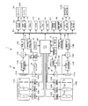
図2は図1の撮影装置1の内部の構成を示すブロック図である。
FIG. 2 is a block diagram showing an internal configuration of the photographing
図2を参照して撮影装置1の内部の構成を説明する。
With reference to FIG. 2, the internal structure of the
この撮影装置1の動作は、統括的にメインCPU100によって制御される。
The operation of the photographing
メインCPU100にはバスBusを介してROM101が接続されており、そのROM101の中にはこの撮影装置1が動作するのに必要なプログラムが格納されている。このプログラムの手順にしたがってメインCPU100は、この撮影装置1の動作を統括的に制御する。
A
まず、図1に示した操作部10内の電源スイッチ10Aが操作されると、メインCPU100は、電源制御部1001を制御してバッテリBTからの電力を電源制御部1001を通して図2の各部に供給させてこの撮影装置1を動作状態に移行させる。こうしてメインCPU100は撮影処理を開始する。なお、AF検出部120とサーチ範囲設定部121とAE/AWB検出部130と画像入力コントローラ114Aとデジタル信号処理部116Aと3D画像生成部117は、DSP(Digital Signal Processor)等のプロセッサで構成されているとし、メインCPU100はそのDSPと連携して処理を実行するとする。また表示制御部119とモニターDISPは、LCDで構成されているものとする。
First, when the
ここで、先に図1で説明した第1の撮影部1Aと第2の撮影部1Bの内部の構成を、図2を参照して説明する。なお第1の撮影部1Aの各構成部材には‘第1の’という文言を付し、第2の撮影部1Bの各構成部材には‘第2’のという文言を付して説明する。
Here, the internal configuration of the
第1の撮影部1Aには、第1のフォーカスレンズFLAを含む第1の撮影光学系110Aと、その第1のフォーカスレンズFLAを光軸方向に移動させる第1のフォーカスレンズ駆動部(以降第1のFレンズ駆動部という)104Aと、被写体が第1の撮影光学系で結像されてなる被写体光を受光してその被写体を表わす画像信号を生成する第1の撮像素子111Aとが備えられている。この第1の撮影光学系110Aには他に第1の絞りIAが配備されており、その第1の絞りIAの開口径を変更する第1の絞り駆動部105Aが備えられている。
The first photographing
また、この第1の撮影光学系100Aはズームレンズになっており、そのズームレンズを所定の焦点距離にする制御を行なうZレンズ駆動部103Aも備えられている。なお、この図2には、撮影光学系全体がズームレンズであることが1枚のレンズZLで模式的に示されている。
The first photographing optical system 100A is a zoom lens, and is also provided with a Z
一方、第2の撮影部1Bにも上記第1の撮影部1Aと同じ様に、第2のフォーカスレンズFLBを含む撮影光学系と、その第2のフォーカスレンズFLBを光軸に方向に移動させる第2のフォーカスレンズ駆動部(以降第2のFレンズ駆動部という)104Bと、被写体が第2の撮影光学系で結像されてなる被写体光を受光してその被写体を表わす画像信号を生成する第2の撮像素子111Bとが備えられている。
On the other hand, in the same way as the first photographing
これらの第1の撮影部1Aと第2の撮影部1Bとで立体視用の画像信号、つまり第1の撮影部1Aでは右眼用の画像信号が生成され、第2の撮影部1Bでは左眼用の画像信号がそれぞれ生成される。
The
第1の撮影部1Aと第2の撮影部1Bとは右眼用の画像信号を生成するか、左眼用の画像信号を生成するかの違いだけで構成が全く同じであって、第1のA/D113Aと第2のA/D113Bで双方の撮影部の画像信号がデジタル信号に変換されてバスBusに導かれた後の処理も同じであるので、第1の撮影部1Aについて画像信号の流れに沿ってその構成を説明していく。
The first
まず、第1の撮影部1Aが捉えている被写体をそのままスルー画としてモニターDISP上に表示する際の動作から説明する。
First, the operation when the subject captured by the first photographing
操作部10内の電源スイッチ10Aが操作されたことを受けてメインCPU100は電源制御部1001を制御して各部にバッテリBTからの電力を供給させてこの撮影装置1を動作状態に移行させる。
In response to the operation of the
メインCPU100は、まず、Fレンズ駆動部104Aと絞り駆動部105Aとを制御して露出およびピントの調整を開始する。さらにTG106Aに指示して撮像素子111Aに電子シャッタを設定させ、例えば1/60秒ごとに撮像素子111Aからアナログ信号処理部112Aに画像信号を出力させる。
First, the
アナログ信号処理部112Aでは、TG106Aからのタイミング信号の供給を受け、撮像素子111Aからの1/60秒ごとの画像信号の供給を受けてノイズの低減処理等が行なわれノイズの低減処理が行なわれたアナログの画像信号が次段のA/D113Aへと供給される。このA/D113AにおいてもTG106Aからのタイミング信号に同期して1/60秒ごとにアナログの画像信号がデジタルの画像信号への変換処理が行なわれる。こうしてA/D113Aで変換され出力されてくるデジタルの画像信号が画像入力コントローラ114Aによって1/60秒ごとにバスBusに導かれ、このバスBusに導かれた画像信号はSDRAM115に記憶される。撮像素子111Aからは1/60秒ごとに画像信号が出力されるので、このSDRAM115の内容は1/60ごとに書き換えられることになる。
In the analog
このSDRAM115に記憶された画像信号は、AF検出部120とAE/AWB検出部130とデジタル信号処理部116Aとを構成するDSPによって1/60ごとにそれぞれ読み出される。
The image signals stored in the
AF検出部120では、メインCPU100がFレンズ駆動部104Aを制御してフォーカスレンズFLAを移動させている最中の1/60ごとにコントラストの検出が行なわれてAFサーチが実施される。このAF検出部120の検出結果に基づいてメインCPU100はFレンズ駆動部104Aに指示して第1のフォーカスレンズFLAを合焦位置に移動させ停止させる。このため、第1の撮影部1Aがどの方向に向けられてもすぐにピントが調整されて、モニターDISP上には、ほぼいつでもピントのあった被写体が表示される。
In the
またAE/AWB検出部130では、輝度の検出とデジタル信号処理部116A内のホワイトバランスアンプに設定するゲインの算出が1/60ごとに行なわれる。メインCPU100は、このAE/AWB検出部130の輝度の検出結果に応じて絞り駆動部105Aを制御して絞りIの開口径を変更させる。またデジタル信号処理部116Aは、AE/AWB検出部130からの検出結果を受けてホワイトバランスアンプのゲインを設定する。
In the AE /
このデジタル信号処理部116Aでは、表示に適した画像信号になるように処理が行なわれ、そのデジタル信号処理部116Aの信号処理により表示に適したものに変換された画像信号が、3D画像生成部117へと供給されてその3D画像生成部117で表示用の右眼用の画像信号が生成され、生成された右眼用の画像信号がVRAM118に記憶される。
In this digital
ここまでの動作と同じ動作が、同じタイミングで第2の撮影部1Bによっても行なわれる。
The same operation as heretofore is performed by the second photographing
したがってVRAM118には、右眼用と左眼用との2種類の画像信号が記憶されることになる。
Therefore, the
メインCPU100は、表示制御部119に、そのVRAM118内の右眼用の画像信号と左眼用の画像信号とを転送してモニターDISP上に画像を表示させる。図1のモニターDISP上に右眼用の画像信号と左眼用の画像信号とが重ねて表示されると、人の眼にはモニターDISP上の画像が立体的に見えるようになる。第1、第2の撮像素子111A,111Bからは1/60ごとに画像信号を出力させ続けているので、VRAM118内の画像信号は1/60ごとに書き換えられモニターDISP上の立体画像も1/60ごとに切り替えられて表示され立体画像が動画となって表示される。
The
ここで、そのモニターDISP上の被写体が参照され操作部10の中のシャッタ釦10Aが半押し操作されると、メインCPU100は、AE/AWB検出部130でシャッタ釦10Cが全押しされる直前に検出されたAE値を受け取って第1、第2の絞り駆動部105A,105Bに指示して第1、第2の絞りIA,IBをAE値に応じた径にさせるとともに、第1のFレンズ駆動部104Aに指示して第1のフォーカスレンズFLAを第1のサーチ領域で移動させながらAF検出部120にコントラストの検出を行なわせる。AF検出部120でコントラストの最大が検出されると、メインCPU100はそのコントラストの最大が得られた合焦位置P1を受け取って第1のフォーカスレンズFLAをその合焦位置P1に停止させる。
Here, when the subject on the monitor DISP is referred to and the
一方、第2の撮影光学系については、第2のフォーカスレンズFLBを、第1のフォーカスレンズFLAの合焦位置に対応した第2のフォーカスレンズFLBの合焦期待位置を含む、第1のサーチ領域よりも狭い第2のサーチ領域内で移動させながらAF検出部120に合焦位置を探索させる。メインCPU100はAF検出部120から探索結果を受け取ってその第2のフォーカスレンズFLBを探索結果が示す合焦位置に停止させる。詳細は後述するが、このときには、AF検出部120が、サーチ範囲設定部121に、第1のフォーカスレンズFLAの合焦位置P1と、フラッシュROM102から読み出したサーチ領域を示すデータ(近傍側偏差Nと遠方側偏差F)とに基づいて第1のフォーカスレンズの合焦位置に対応した合焦期待位置を含む、第1のサーチ領域よりも狭い第2のサーチ領域を算出させ、メインCPU100がその第2のサーチ領域の算出結果を受け取って第2のFレンズ駆動部104Bに指示してその第2のサーチ領域で合焦位置を探索するAFサーチを行なわせる。
On the other hand, for the second imaging optical system, the first search includes the second focus lens FLB including the expected focus position of the second focus lens FLB corresponding to the focus position of the first focus lens FLA. The
このように第1の撮影部1AのフォーカスレンズFLAには従来どおりのAFサーチを行なわせ、第2の撮影部1Bには第2のフォーカスレンズFLBの合焦期待位置を含む、第1の範囲よりも狭い第2の範囲でAFサーチを行なわせても、第2の撮影部1Bについては合焦期待位置を挟んだ短い領域のAFサーチを行なわせるだけで済むので、従来とほぼ同じ程度の時間でAFサーチが終了する。
As described above, the focus lens FLA of the
そしてシャッタ釦10Cが全押しされると、メインCPU100は、第1、第2のTG106A,106Bに電子シャッタを設定させて静止画の撮影処理を開始する。メインCPU100は、電子シャッタのオフタイミングで第1、第2の撮像素子111A,111Bから画像信号を第1、第2のアナログ信号処理部112A,112Bへと出力させ、第1、第2のアナログ信号処理部112A,112Bにノイズの低減処理を行なわせる。その後、第1、第2のA/D113A,113Bでアナログの画像信号をデジタルの画像信号に変換させる。このときには第1、第2のデジタル信号処理部116A,116BにAE/AWB検出部130で検出された全押し直前に検出されたホワイトバランス情報に基づいて内部のホワイトバランスアンプにゲインが設定されていて適切なホワイトバランス調整が行なわれる。
When the shutter button 10C is fully pressed, the
ここでメインCPU100の指示にしたがって第1、第2の画像入力コントローラ114Aが、第1、第2のA/D113A,113Bで変換されたデジタルの画像信号をバスBus側に導いてバスBusを経由して一旦すべての画像信号をSDRAM115に記憶する。その後、今度はデジタル信号処理部116A,116BがSDRAM115の画像信号を読み出して表示に適した画像信号に変換し変換した画像信号を3D画像生成部117へと転送する。こうして第1、第2のデジタル信号処理部116A,116Bで表示に適した右眼用の画像信号と左眼用の画像信号とが生成され、3D画像生成部117でモニターDISPに表示するための表示用の右眼用の画像信号と左眼用の画像信号が生成された後、メインCPU100は、3D画像生成部117内の右眼用の画像信号と左目用の画像信号を、バスBusを使って圧縮・伸長処理部150に供給する。メインCPU100は、この圧縮・伸張処理部150に画像データの圧縮を行なわせた後、その圧縮された画像データをメディア制御部にバスBusを使って転送するとともに、その圧縮や撮影に係るヘッダ情報をメディア制御部160に供給してメディア制御部160に画像ファイルを生成させメモリカード161にその画像ファイルを記録させる。
Here, in accordance with the instruction from the
この実施形態の構成にすると、第1の撮影部1Aと第2の撮影部1Bとの間に固体差があっても、その固体差が解消され各々の撮影光学系の第1、第2のフォーカスレンズが的確な合焦位置にいままでとほぼ同じ時間で各々配置される。なお図2には、他にフラッシュ制御部180とそのフラッシュ制御部180からの指示を受けて図1の発光窓WDからフラッシュを発光するフラッシュ181や現在の時刻を検知するための時計部W、さらにはこの撮影装置1の姿勢を検出する姿勢検出センサ190が図示されている。
With the configuration of this embodiment, even if there is a solid difference between the first photographing
本実施形態では、メインCPU100と第1、第2のFレンズ駆動部104A,104Bと第1、第2のフォーカスレンズFLA,FLBとフラッシュROM102とAF検出部120とサーチ範囲設定部121とで、本発明にいう合焦位置決定手段の一例が構成される。
In the present embodiment, the
ここまで説明してきた動作をより分かり易くするためにメインCPU100が第1、第2のFレンズ駆動部104A,104Bに指示して第1、第2のフォーカスレンズを移動させながらAF検出部120に行なわせる合焦位置決定方法を、図3と図4を参照して分かり易く説明する。
In order to make the operation described so far easier to understand, the
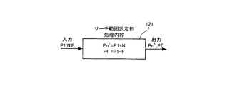
図3は、メインCPU100が、第1のFレンズ駆動部104Aと第2のFレンズ駆動部104Bに指示して第1および第2のフォーカスレンズFLA,FLBを移動させながらAF検出部120に行なわせる合焦位置決定方法を説明する図である。また図4は、サーチ範囲設定部の処理内容を説明する図である。
In FIG. 3, the
図3(a)には、第1のフォーカスレンズFLAの第1のサーチ領域が示されており、図3(b)には第2のフォーカスレンズFLBの第2のサーチ領域が示されている。 FIG. 3A shows a first search area of the first focus lens FLA, and FIG. 3B shows a second search area of the second focus lens FLB. .
図3(a)に示す様に、メインCPU100は第1のFレンズ駆動部104Aに第1のサーチ領域(PnからPf)で第1のフォーカスレンズFLAを移動させながらAF検出部120にコントラストの最大を検出させることにより合焦位置を探索させる。ここでメインCPU100はAF検出部120が検出したAF評価値(コントラスト)が最大となる合焦位置P1を受け取って第1のFレンズ駆動部104Aに指示してフォーカスレンズFLAをその合焦位置P1に移動させ停止させる。
As shown in FIG. 3A, the
その後AF検出部120は、サーチ範囲設定部121に合焦位置P1を入力するとともに、フラッシュROM102から第2のサーチ領域に関する定数(近傍側偏差N、遠方側偏差F)を読み出してサーチ範囲設定部121に転送し、サーチ範囲設定部121に第2のサーチ領域を算出させる。メインCPU100は、その算出結果をバスBusを介して受け取って第2のFレンズ駆動部104Bに指示して第2のフォーカスレンズFLBを第2のサーチ範囲(Pn´からPf´)で移動させながらAF検出部120に合焦位置を探索させる。
After that, the
そしてメインCPU100はAF検出部120が検出した第2の撮影部1BのAF評価値(コントラスト)が最大となる合焦位置P2を受け取って第2のFレンズ駆動部104Aに指示してフォーカスレンズFLBをその合焦位置P2に停止させる。
The
つまり、図4に示す様に、サーチ範囲設定部121では、AF検出部120で検出された第1のフォーカスレンズFLAの合焦位置P1とフラッシュROM102内に予め記憶されていた近傍側偏差Nと遠方側偏差Fとに基づいて、第2のサーチ領域となるサーチ開始位置Pn´をPn´=Pn+Nという式から算出し、サーチ終了位置Pf´をPf´=P1−Fという式から算出する。なお、フラッシュROM102内には、近傍側偏差Nと遠方側偏差Fを表わすデータの組み合わせが、第1の撮影部1Aと第2の撮影部1Bとの間の固体差を解消することができるように焦点距離ごと、さらに合焦位置ごとに複数記憶されているとする。
That is, as shown in FIG. 4, in the search
メインCPU100はこの算出結果を受け取って第2のFレンズ駆動部104Bに指示して、第2のフォーカスレンズFLBを第1のサーチ領域よりも狭い第2のサーチ領域(Pn´からPf´)で移動させながら合焦位置P2をAF検出部120に探索させ探索させた合焦位置を受け取って第2のレンズ駆動部104Bに指示して第2のフォーカスレンズFLBを配置する。
The
この構成にすると、第2のフォーカスレンズFLBを第1のフォーカスレンズFLAの合焦位置に対応した合焦期待位置を含んだ狭い第2のサーチ領域をAFサーチさせるだけで済むので、従来のAF時間とさほど変わらない時間で、双方の撮影部の固体差が解消された正確な合焦位置決定が行なわれる。 With this configuration, the second focus lens FLB only needs to be AF searched for a narrow second search region including the expected focus position corresponding to the focus position of the first focus lens FLA. In a time that is not much different from the time, an accurate in-focus position determination in which the individual difference between the two photographing units is eliminated is performed.
最後に、メインCPU100とAF検出部120とサーチ範囲設定部121等を構成するDSPとが連携して実行する合焦位置決定処理の手順をフローチャートを参照しながら説明する。
Finally, the procedure of the in-focus position determination process executed in cooperation with the
図5は、メインCPU100がAF検出部120やAE/AWB検出部130等を構成するDSPと連携して実行する合焦位置決定の処理手順を示すフローチャートである。
FIG. 5 is a flowchart showing a processing procedure for determining the in-focus position executed by the
ステップS501でメインCPU100が、シャッタ釦10Cが半押しされたかどうかを判定する。このステップS501でメインCPU100が、シャッタ釦10Cが半押しされていないと判定するとNo側へ進んでステップS501の処理を繰り返し、このステップS501でシャッタ釦10Cが半押しされたと判定するとYes側へ進む。そしてYes側へ進むとステップS502でメインCPU100からの処理開始指示を受けてDSP内のAE/AWB検出部130がAE動作を開始し、さらにステップS503へ進んで、DSP内のAF検出部120がAF動作を開始する。
In step S501, the
ステップS503のAF動作の開始に伴ってステップS504で、メインCPU100が、まず第1のサーチ領域(図4のPnからPf)を第1のFレンズ駆動部104Aに設定し、次のステップS505で第1撮影光学系の第1のフォーカスレンズFLAを移動させながらAF検出部120に合焦位置の検出を行なわせる。
With the start of the AF operation in step S503, in step S504, the
そしてステップS506で、AF検出部120が、第1の撮影部1Aが備える撮影光学系内の第1のフォーカスレンズFLAの合焦位置P1を取得したことを受けてメインCPU100は第1のFレンズ駆動部104Aに指示して第1のフォーカスレンズFLAをその第1の合焦位置P1に停止させる。
In step S506, the
次のステップS507でAF検出部120がその合焦位置P1をサーチ範囲設定部121に供給するとともに、フラッシュROM102からサーチの開始位置データNとサーチの終了位置データFを読み出してサーチ範囲設定部121に供給し、サーチ範囲設定部121に第2のサーチ領域を図4に示すPn´=P1+N、Pf´=P1−Fという式を使って算出させる。メインCPU100はその算出結果を受け取って第2のFレンズ駆動部104Bにそのサーチ開始位置Pn´とサーチ終了位置Pf´とを設定して、ステップS508で第2のサーチ範囲でフォーカスレンズFLBを移動させながらAF検出部120に第2の合焦位置P2を検出させる。ステップS508で第2の合焦位置P2を検出させると、ステップS509でメインCPU100はその合焦位置P2をAF検出部120から取得して、ステップS510で第2のFレンズ駆動部104Bに指示して第2のフォーカスレンズFLBをその合焦位置P2に移動させ停止させる。ステップS511でAF動作を終了した後、ステップS512でメインCPU100はシャッタ釦10Cの全押しを待ち受ける。このステップS512でメインCPU100が、シャッタ釦10Cが全押しされないと判定するとNo側へ進んでステップS512の処理を繰り返し、シャッタ釦10Cが全押しされたと判定すると、Yes側へ進んで撮影処理を実行してこのフローの処理を終了する。
In the next step S507, the
本実施形態では、ステップS504からステップS506までの処理が本発明にいう第1のステップの処理の一例に相当し、ステップS507からステップS510までの処理が本発明にいう第2のステップの処理の一例に相当する。 In this embodiment, the process from step S504 to step S506 corresponds to an example of the process of the first step according to the present invention, and the process from step S507 to step S510 is the process of the second step according to the present invention. It corresponds to an example.
メインCPU100と、AF検出部120やサーチ範囲設定部121等を構成するDSPとが、図5のフローを実行すると、従来と同じ程度の時間であってしかも第1の撮影部1Aと第2の撮影部1Bとの間の固体差が解消された正確な合焦位置決定が実施される。
When the
図6は、第2実施形態を示す図である。 FIG. 6 is a diagram illustrating a second embodiment.
この第2実施形態でも図1の外観の撮影装置1が用いられるとする。この図6には、図2とほぼ同じブロック図が示されており、図2のサーチ範囲設定部121の部分が合焦位置演算部121Aに置き換えられている。
Also in the second embodiment, it is assumed that the
また、図7は、メインCPU100が、第1のFレンズ駆動部104Aに指示して第1のフォーカスレンズを移動させながらAF検出部120に行なわせた後、第2のフォーカスレンズについてはフラッシュROM102内の偏差Dfを使って第2のフォーカスレンズFLBを合焦位置に移動させ停止させる構成に変更した合焦位置決定方法を説明する図である。さらに図8は合焦位置演算部121Aの処理内容を説明する図である。
Also, FIG. 7 shows that the
第1実施形態では、メインCPU100が第2のFレンズ駆動部104Bに指示して第2のフォーカスレンズFLBを第1のフォーカスレンズの合焦位置に対応する合焦期待位置を含んだ短い第2のサーチ領域でのAFサーチを行なわせることで、従来とさほど変わらない時間で、固体差を解消し、かつ正確な合焦位置決定を可能にする構成を提案した。
In the first embodiment, the
これに対して第2実施形態では、この撮影装置1を市場に出荷する前の製造時に第1の撮影部1Aと第2の撮影部1Bとの間の固体差を表わす合焦位置の偏差を予め取得しその偏差をフラッシュROM102に記憶しておいて、撮影時には第1のフォーカスレンズのみを移動させながらAF検出部120に第1の合焦位置P1の検出を行なわせ、第2のフォーカスレンズFLBについては第2のフォーカスレンズFLBを移動させながらのAFサーチを省略して合焦位置演算部121Aに偏差Dfを使って第2の合焦位置P2を算出させ算出させた位置に第2のフォーカスレンズを移動させ停止させる構成を提案している。
On the other hand, in the second embodiment, the deviation of the in-focus position representing the individual difference between the
この構成にすると、固体差を解消し、かつ正確な合焦位置決定を従来とほぼ同じ時間で行なうことができる。この第2の実施形態では、メインCPU100と第1、第2のFレンズ駆動部104A,104Bと第1、第2のフォーカスレンズFLA,FLBとフラッシュROM102とAF検出部120と合焦位置演算部121Aとで、本発明にいう合焦位置決定手段の一例が構成される。
With this configuration, it is possible to eliminate individual differences and to perform accurate in-focus position determination in substantially the same time as in the past. In the second embodiment, the
図7を参照して第2実施形態を説明する。 A second embodiment will be described with reference to FIG.
図7(a)には、第1のフォーカスレンズFLAの第1のサーチ領域が示されており、図7(b)には第2のフォーカスレンズFLBをサーチさせずに合焦位置演算部121Aに算出させた第2の合焦位置P2に第2のフォーカスレンズを移動させ停止させるということが示されている。
FIG. 7A shows the first search area of the first focus lens FLA, and FIG. 7B shows the in-
図7(a)に示す様にメインCPU100がFレンズ駆動部104Aに指示して第1のフォーカスレンズFLAを第1のサーチ領域(PnからPf)で移動させながらAF検出部120に合焦位置P1を検出させるところまでは第1実施形態と同じである。
As shown in FIG. 7A, the
その後の第2のフォーカスレンズFLBの合焦位置決定については、AF検出部120が第1のフォーカスレンズの上記合焦位置P1を合焦位置演算部102Aに供給するとともに上記偏差DfをフラッシュROM102から読み出しその偏差Dfをその合焦位置演算部121Aに供給して、合焦位置演算部121Aに図8に示すP2=P1−Dfという式を使って合焦位置P2を算出させた後、メインCPU100がその合焦位置演算部121Aの算出結果を受け取って第2のフォーカスレンズFLBをその算出された合焦位置に移動させ停止させる。
For determining the in-focus position of the second focus lens FLB thereafter, the
この構成にすると、第2のフォーカスレンズFLBをAFサーチさせる必要がなくなるので、従来と同じ時間でAFサーチが終了し、しかも第1の撮影部と第2の撮影部との間の固体差が解消されて的確な合焦位置に第1、第2のフォーカスレンズが各々配置される。 With this configuration, since it is not necessary to perform the AF search of the second focus lens FLB, the AF search is completed in the same time as the conventional method, and the solid difference between the first photographing unit and the second photographing unit is The first and second focus lenses are respectively disposed at the in-focus positions that have been eliminated.
また、この第2の実施形態では、ズームスイッチ10Dが操作されて焦点距離が変更されると、第1、第2のフォーカスレンズFLA,FLBの合焦位置が変化するということを考慮して、フラッシュROM102内には異なる焦点距離ごとの偏差が記録され、AF検出部120が、メインCPU100から現在の焦点距離情報を受け取ってその焦点距離情報に応じた偏差を読み出す構成にしてある。この構成にすると、ズームスイッチ10Dが操作され焦点距離が変更されても正確な合焦位置決定が行なわれる。
In the second embodiment, in consideration that the in-focus positions of the first and second focus lenses FLA and FLB change when the focal length is changed by operating the
こうしてメインCPU100が、合焦位置演算部121Aで算出された結果(P2=P1−Df)を受け取って図7(b)に示す様に、その合焦位置P2に第2のフォーカスレンズFLBをAFサーチをせずに配置する構成にしても良い。
In this way, the
この第2実施形態の構成にしても第1の実施形態と同じ様に、第1の撮影部と第2の撮影部との間の固体差が解消され、第1の撮影部1Aが備える第1のフォーカスレンズと第2の撮影部1Bが備える第2のフォーカスレンズ各々に的確な合焦位置が得られる。
Even in the configuration of the second embodiment, as in the first embodiment, the solid difference between the first imaging unit and the second imaging unit is eliminated, and the
また、この第2の実施形態においては、第2のフォーカスレンズを移動させずに、第1の合焦位置から偏差Dfだけ偏倚した位置に第2のフォーカスレンズFLBを移動させ停止させる構成にしてあるので、従来とほぼ同じ時間でAFサーチが終了する。 In the second embodiment, the second focus lens FLB is moved to a position deviated by the deviation Df from the first focus position and stopped without moving the second focus lens. As a result, the AF search is completed in approximately the same time as in the prior art.
最後に、第2実施形態のメインCPU100が、AF検出部120と合焦位置演算部121Aを構成するDSPと連携して実行する合焦位置決定処理の手順を図9のフローチャートを参照しながら説明する。
Finally, the focus position determination process executed by the
図9は、第2実施形態のメインCPU100が、AF検出部120等を構成するDSPと連携して処理を実行する合焦位置決定の処理手順を示すフローチャートである。
FIG. 9 is a flowchart illustrating a processing procedure for determining the in-focus position in which the
ステップS507の処理がステップS507Aに変更され、ステップS508、ステップS509の処理が省略されている以外は、図5のフローの処理と同じであるので、処理が変更されたところを説明する。 Since the process of step S507 is changed to step S507A and the processes of step S508 and step S509 are omitted, the process is the same as the process of the flow of FIG.
ステップS507Aで、AF検出部120がフラッシュROM102から偏差Dfを読み出して合焦位置演算部102Aに供給し、第2のフォーカスレンズFLBの合焦位置P2を算出させ、ステップS510でメインCPU100が合焦位置演算部121Aに算出させた合焦位置P2を受け取ってFレンズ駆動部104Bに指示してフォーカスレンズFLBを合焦位置P2に移動させ停止させる。
In step S507A, the
本実施形態では、ステップS504からステップS506までの処理が本発明にいう第1のステップの処理の一例に相当し、ステップS507AからステップS510までの処理が本発明にいう第2のステップの処理の一例に相当する。 In this embodiment, the process from step S504 to step S506 corresponds to an example of the process of the first step according to the present invention, and the process from step S507A to step S510 is the process of the second step according to the present invention. It corresponds to an example.
メインCPU100とAF検出部120等を構成するDSPが、図9のフローを実行すると、第1の撮影部1Aと第2の撮影部1Bとの間の固体差が解消された的確な合焦位置決定が従来とほぼ同じ時間で実施される。
When the DSP that constitutes the
図10〜図13は、第3実施形態を説明する図である。 10-13 is a figure explaining 3rd Embodiment.
この第3実施形態においても図1の外観の撮影装置1が用いられるとする。
Also in the third embodiment, it is assumed that the
図10は、図2と同様に図1の撮影装置の内部構成を示す図であって、サーチ範囲設定部121が偏差検出部121Bに置き換えられている以外は、図2と同じ構成を示す図である。また、図11は、メインCPU100が、初回の撮影時には第1のFレンズ駆動部104Aと第2のFレンズ駆動部104Bに指示して第1および第2のフォーカスレンズFLA,FLBを移動させながらAF検出部120に第1、第2の合焦位置P1,P2の検出を行なわせこの合焦位置の偏差DfをDRAM115に記憶しておいて、次回以降の撮影においては第1のFレンズ駆動部104Aに指示して第1のフォーカスレンズFLAを移動させながらAF検出部120に第1の合焦位置P1の検出を行なわせ、偏差検出部に偏差Dfと第1の合焦位置P1を供給して第2のフォーカスレンズFLBの第2の合焦位置を算出させるという合焦位置決定方法を説明する図である。また図12は、偏差検出部121Bの処理内容を説明する図である。
FIG. 10 is a diagram showing the internal configuration of the imaging apparatus of FIG. 1 as in FIG. 2, and shows the same configuration as FIG. 2 except that the search
この第3実施形態では、初回の撮影時には第1実施形態の合焦位置決定方法を使って第2のフォーカスレンズを合焦位置P1に移動させ停止させると共に、その初回の撮影時に第1の撮影部1Aと第2の撮影部1Bとの固体差を示す偏差Dfを取得してSDRAM115に記憶しておいて、以降の撮影時においては第2実施形態の合焦位置決定方法を使ってAF検出部120がSDRAM115から偏差Dfを読み出して偏差検出部121Bに供給しその偏差検出部121Bに第2の合焦位置P2を算出させ、メインCPU100がその第2の合焦位置P2を偏差検出部121Bから受け取って第2の駆動部104Bに指示してその偏差Dfだけ偏倚した位置に第2のフォーカスレンズFLBを移動させ停止させる構成を提案している。
In the third embodiment, at the time of the first shooting, the second focus lens is moved to the focusing position P1 and stopped using the focus position determination method of the first embodiment, and at the first shooting, the first shooting is performed. The deviation Df indicating the individual difference between the
この第3実施形態では、メインCPU100と第1、第2のFレンズ駆動部104A,104Bと第1、第2のフォーカスレンズFLA,FLBとフラッシュROM102とAF検出部120と偏差検出部121Bとで、本発明にいう合焦位置決定手段の一例が構成される。
In the third embodiment, the
ここで、図11を参照してメインCPU100が、第1のFレンズ駆動部104Aと第2のFレンズ駆動部104Bに指示して第1および第2のフォーカスレンズを移動させながらAF検出部120に行なわせる合焦位置決定方法を説明する。
Here, referring to FIG. 11, the
図11(a)、(b)には、初回の撮影においては、上記第1実施形態と同じ様に、第1のフォーカスレンズFLAおよび第2のフォーカスレンズFLBを移動させながらAFサーチが行なわれるということが示されている。また図11(c)、(d)には、2回目以降の撮影においては、第1のフォーカスレンズFLAを移動させながらAFサーチが行われることと、第2のフォーカスレンズFLBについては初回の撮影により得られた偏差を使って第2のフォーカスレンズが合焦位置に配置されるということが示されている。 In FIGS. 11A and 11B, in the first shooting, an AF search is performed while moving the first focus lens FLA and the second focus lens FLB, as in the first embodiment. It is shown that. Further, in FIGS. 11C and 11D, in the second and subsequent shooting, the AF search is performed while moving the first focus lens FLA, and the first shooting is performed for the second focus lens FLB. It is shown that the second focus lens is arranged at the in-focus position using the deviation obtained by the above.
図11に示す様に、初回の撮影においては、第1実施形態と同様に、メインCPU100が第1のFレンズ駆動部104Aに指示して第1のサーチ領域(PnからPf)で第1のフォーカスレンズFLAを移動させながらAF検出部120に合焦位置を探索させる。ここでメインCPU100はAF検出部120が検出したAF評価値(コントラスト)が最大となる合焦位置P1を受け取って第1のFレンズ駆動部104Aに指示してフォーカスレンズFLAをその合焦位置P1に停止させる。
As shown in FIG. 11, in the first shooting, as in the first embodiment, the
その後AF検出部120は、偏差検出部121に合焦位置P1を入力するとともに、フラッシュROM102から第2のサーチ領域に関する定数(近傍側偏差N、遠方側偏差F)を読み出して偏差検出部121Bに転送し、偏差検出部121Bに第2のサーチ領域を算出させる。メインCPU100は、その算出結果をバスBusを経由して受け取って第2のFレンズ駆動部104Bに指示して第2のフォーカスレンズFLBを第2のサーチ範囲(Pn´からPf´)で移動させながらAF検出部120に合焦位置を探索させる。
After that, the
そしてメインCPU100はAF検出部120が検出した第2の撮影部1BのAF評価値(コントラスト)が最大となる合焦位置P2を受け取って第2のFレンズ駆動部104Aに指示してフォーカスレンズFLBをその合焦位置P2に停止させる。
The
このようにすると、第1実施形態と同様に、初回の撮影においては従来のAF時間とさほど変わらない時間で、2つの撮影部の間の固体差が解消された正確な合焦位置決定が行なわれる。 In this way, as in the first embodiment, in the first shooting, an accurate in-focus position determination in which the solid difference between the two shooting units is eliminated is performed in a time that is not much different from the conventional AF time. It is.
ここで、本実施形態では、偏差検出部121Bが第1の合焦位置P1と第2の合焦位置P2との間の偏差DfをP1−P2という式を使って算出し偏差DfをSDRAM115に記憶する。
Here, in the present embodiment, the
そして次回以降の撮影においては、図11(c)、(d)に示す様にメインCPU100が第1のFレンズ駆動部104Aに指示して第1のフォーカスレンズFLAを第1のサーチ領域(PnからPf)で移動させながらAF検出部120に合焦位置P1を検出させた後、AF検出部115が、SDRAM115内の偏差Dfを読み出しその偏差Dfをその偏差検出部121Bに供給して、第2の撮影部1Bの第2のフォーカスレンズFLBの合焦位置P2を算出させ、メインCPU100がその合焦位置P2を受け取って第2のFレンズ駆動部104Bに指示して第2のフォーカスレンズFLBをその合焦位置P2に移動させ停止させる。
In the next and subsequent shootings, as shown in FIGS. 11C and 11D, the
この構成にすると、2回目以降の撮影においては、第2実施形態と同様に、AFサーチを行なわせる必要がなくなって従来のAF時間と同じ時間で第1の撮影部と第2の撮影部との間の固体差が解消された正確な合焦位置決定が行なわれる。 With this configuration, in the second and subsequent shootings, as in the second embodiment, it is not necessary to perform an AF search, and the first shooting unit and the second shooting unit are performed at the same time as the conventional AF time. An accurate in-focus position is determined in which the difference between the individual objects is eliminated.
最後に、合焦位置決定手段を構成するメインCPU100が、AF検出部120と偏差検出部121Bを構成するDSPと連携して実行する合焦位置決定処理の手順をフローチャートを参照しながら説明する。
Finally, the procedure of the focus position determination process executed by the
図13は、メインCPU100がDSPと連携して実行する合焦位置決定の処理手順を示すフローチャートである。
FIG. 13 is a flowchart showing a processing procedure for determining the in-focus position executed by the
ステップS501でメインCPU100がシャッタ釦10Cが半押しされたかどうかを判定する。このステップS501でメインCPU100がシャッタ釦10Cが半押しされていないと判定するとNo側へ進んでステップS501の処理を繰り返し、このステップS501でシャッタ釦10Cが半押しされたと判定すると、Yes側へ進む。Yes側へ進むとステップS502でメインCPU100からの処理開始指示を受けてDSP内のAE/AWB検出部130がAE動作を開始し、さらにステップS503Aへ進んで初回の撮影か否かを判定する。このステップS503AでメインCPU100が初回の撮影であると判定すると、Yes側へ進んでメインCPU100からの撮影開始指示を受けてAF検出部がAF動作を開始する。なお、ステップS503Aにおける、初回の撮影か否かは、より具体的には、SDRAM115内に有効な偏差Dfの値が記憶されているか否かによって判定する。
In step S501, the
ステップS504で、メインCPU100が、まず第1のサーチ領域(図4のPnからPf)を第1のFレンズ駆動部104Aに設定し、次のステップS505で第1撮影光学系の第1のフォーカスレンズFLAを移動させながらAF検出部120に合焦位置の検出を行なわせる。
In step S504, the
そしてステップS506で、AF検出部120が、第1の撮影部1Aが備える撮影光学系内の第1のフォーカスレンズFLAの合焦位置P1を取得したことを受けてメインCPU100は第1のFレンズ駆動部104Aに指示して第1のフォーカスレンズFLAをその第1の合焦位置P1に停止させる。
In step S506, the
ステップS507でAF検出部120がその合焦位置P1を偏差検出部121Bに供給するとともに、フラッシュROM102から近傍側偏差Nと遠方側偏差Fを読み出して偏差検出部121に供給し、偏差検出部121Bに第2のサーチ領域を図12の式を使って算出させる。ステップS507でメインCPU100がその第2のサーチ領域を偏差検出部121Bから取得してステップS508で第2のFレンズ駆動部104Bにそのサーチ開始位置Pn´とサーチ終了位置Pf´とを設定して、ステップS509で第2のサーチ範囲でフォーカスレンズFLBを移動させながらAF検出部120に合焦位置P2を検出させる。ステップS510でメインCPU100がその合焦位置P2をAF検出部120から受け取って第2のFレンズ駆動部104Bに指示して第2のフォーカスレンズFLBをその合焦位置P2に移動させ停止させる。次のステップS5091でAF検出部120が偏差検出部121Bに合焦位置P1と合焦位置P2との偏差を算出させ、その偏差をSDRAM115に記憶する。
In step S507, the
ステップS511でAF動作を終了した後、ステップS512でメインCPU100はシャッタ釦10Cの全押しを待ち受ける。このステップS512でメインCPU100が、シャッタ釦10Cが全押しされないと判定するとNo側へ進んでステップS512の処理を繰り返し、シャッタ釦10Cが全押しされたと判定すると、Yes側へ進んで撮影処理を実行する。
After completing the AF operation in step S511, in step S512, the
ここまでで初回の撮影処理が終了する。 This completes the first shooting process.
次回の撮影以降においては、ステップS503でNo側へ進んで、ステップS514で、まず第1のサーチ領域(図11(c)のPnからPf)を第1のFレンズ駆動部104Aに設定する。次のステップS515で第1撮影光学系の第1のフォーカスレンズFLAを移動させながらAF検出部120に合焦位置の検出を行なわせる。そしてAF検出部120に検出させた合焦位置P1に基づいて第1のFレンズ駆動部104Aに指示して第1のフォーカスレンズFLAを合焦位置P1に移動させ停止させる。
After the next shooting, the process proceeds to No in step S503, and first, in step S514, the first search area (Pn to Pf in FIG. 11C) is set in the first F
ステップS516で、AF検出部120が、第1の撮影部1Aが備える撮影光学系内の第1のフォーカスレンズFLAの合焦位置P1を取得して、偏差検出部121Bに供給するとともに、SDRAM115内の偏差Dfを読み出して偏差検出部121Bに供給する。ステップS517で偏差検出部121Bに図12のP2=P1−Dfという式を使って第2の合焦位置P2を検出させる。メインCPU100は、その第2の合焦位置P2を偏差検出部121Bから受け取って第2のレンズ駆動部104Bに指示して第2のフォーカスレンズを第2の合焦位置P2に移動させ停止させる。
In step S516, the
本実施形態では、図13の右側の初回の撮影に係るフローのステップS504からステップS509までの処理が本発明にいう第1のステップの処理の一例に相当し、図13の右側の初回の撮影に係るフローのステップS5091の処理が本発明にいう第2のステップの処理の一例に相当し、図13の左側の2回目以降の撮影に係るフローのステップS514からステップS517までの処理が本発明にいう第3のステップの処理の一例に相当する。 In the present embodiment, the processing from step S504 to step S509 in the flow relating to the first shooting on the right side of FIG. 13 corresponds to an example of the processing of the first step according to the present invention, and the first shooting on the right side in FIG. The processing in step S5091 of the flow according to this embodiment corresponds to an example of the processing in the second step according to the present invention, and the processing from step S514 to step S517 in the flow relating to the second and subsequent shootings on the left side in FIG. This corresponds to an example of the process of the third step.
この構成にすると、初回の撮影においては、第1実施形態と同様に、従来とほぼ同じ程度の時間でAFサーチが終了し、かつ第1の撮影部と第2の撮影部との間の固体差が解消されて正確な合焦位置決定が行なわれ、さらに次回以降の撮影においては、第2実施形態と同様に、従来と同じ時間でAFサーチが終了し、かつ第1の撮影部と第2の撮影部との間の固体差が解消されて正確な合焦位置決定が行なわれる。 With this configuration, in the first shooting, as in the first embodiment, the AF search is completed in approximately the same amount of time as in the prior art, and the solid state between the first shooting unit and the second shooting unit is obtained. The difference is eliminated and accurate in-focus position determination is performed. Further, in the next and subsequent shootings, as in the second embodiment, the AF search is completed at the same time as the prior art, and the first shooting unit and the first shooting unit The individual difference between the two photographing units is eliminated, and an accurate in-focus position is determined.
なお、上記第3の実施形態では、偏差DfをSDRAM115に記憶する構成にしたが、フラッシュROM102に記憶する構成にしても良い。フラッシュROM102に記憶する構成にすると、電源がオフされて電源がオンされた後の初回の撮影で偏差を記憶する必要がなくなる。実装された後でも書換えが自在な不揮発性のフラッシュROMを用いると、第2の実施形態のように製造時にフラッシュROMに記憶する必要がなくなって、撮影者が操作により1週間毎や1ヶ月毎等に偏差記憶部に自在に偏差を記憶する構成に拡張することができる。
In the third embodiment, the deviation Df is stored in the
また、上記実施形態では、立体撮影を行なう撮影装置についての説明を行なったが、本発明は、2つの撮影部でパノラマ撮影を行なう撮影装置であっても良く、2つの撮影部各々で異なる感度の撮影を行なう撮影装置であっても良く、2つの撮影部各々で色味の異なる撮影を行なう撮影装置であっても良く、2つの撮影部各々で輝度の異なる撮影を行なう撮影装置であっても良い。いずれの撮影装置でも本発明の合焦位置決定方法は適用可能である。 In the above-described embodiment, the photographing apparatus that performs stereoscopic photographing has been described. However, the present invention may be a photographing apparatus that performs panoramic photographing with two photographing units, and each of the two photographing units has different sensitivity. May be a photographing device that shoots images with different colors in each of the two photographing units, or a photographing device that performs photographing with different luminance in each of the two photographing units. Also good. The focusing position determination method of the present invention can be applied to any photographing apparatus.
1 撮影装置
1A 第1の撮影部
1B 第2の撮影部
100 メインCPU
101 ROM
102 フラッシュROM
104A 第1のFレンズ駆動部
104B 第2のFレンズ駆動部
110A 第1の撮影光学系
110B 第2の撮影光学系
111A 第1の撮像素子
111B 第2の撮像素子
112A 第1のアナログ信号処理部
112B 第2のアナログ信号処理部
116A 第1のデジタル信号処理部
116B 第2のデジタル信号処理部
120 AF検出部
121 サーチ範囲設定部
121A 合焦位置演算部
121B 偏差検出部
130 AE・AWB検出部
DESCRIPTION OF
101 ROM
102 flash ROM
104A First F
Claims (5)
第2のフォーカスレンズを含む第2の撮影光学系と、該第2のフォーカスレンズを光軸方向に移動させる第2のフォーカスレンズ駆動部と、被写体が前記第2の撮影光学系で結像されてなる被写体光を受光して該被写体を表わす画像信号を生成する第2の撮像素子とを有する第2の撮影部と、 A second photographing optical system including a second focus lens, a second focus lens driving unit that moves the second focus lens in the optical axis direction, and a subject is imaged by the second photographing optical system. A second imaging unit having a second imaging element that receives the subject light and generates an image signal representing the subject;
前記第1および第2のフォーカスレンズ駆動部各々に指示し前記第1および第2のフォーカスレンズ各々を光軸方向に移動させながら各々の合焦位置を探索し該第1及び該第2のフォーカスレンズ各々を各々の合焦位置に停止させる合焦位置決定手段と、 Each of the first and second focus lens driving units is instructed to search each in-focus position while moving the first and second focus lenses in the optical axis direction, and the first and second focus lenses are searched. Focusing position determining means for stopping each lens at each focusing position;
前記合焦位置決定手段により探索された前記第2のフォーカスレンズの合焦位置の、前記合焦位置決定手段により探索された前記第1のフォーカスレンズの合焦位置からの偏差を記憶する偏差記憶部とを備え、 Deviation memory for storing the deviation of the in-focus position of the second focus lens searched for by the in-focus position determining means from the in-focus position of the first focus lens searched for by the in-focus position determining means. With
前記合焦位置決定手段は、 The in-focus position determining means includes
前記偏差記憶部に前記偏差が記憶されていない場合には、前記第1のフォーカスレンズを所定の第1のサーチ領域内で移動させながら合焦位置を探索して該第1のフォーカスレンズを合焦位置に停止させ、前記第2の撮影光学系については、前記第2のフォーカスレンズを、前記第1のフォーカスレンズの合焦位置に対応した該第2のフォーカスレンズの合焦期待位置を含む、前記第1のサーチ領域よりも狭い第2のサーチ領域内で移動させながら合焦位置を探索して、該第2のフォーカスレンズを合焦位置に停止させる第1の合焦位置決定を実行し、 If the deviation is not stored in the deviation storage unit, the in-focus position is searched by moving the first focus lens within a predetermined first search area to adjust the first focus lens. In the second imaging optical system, the second focus lens includes the expected focus position of the second focus lens corresponding to the focus position of the first focus lens. The focus position is searched while moving in the second search area narrower than the first search area, and the first focus position determination for stopping the second focus lens at the focus position is executed. And
前記偏差記憶部に前記偏差が記憶されている場合には、第1の撮影光学系について、前記第1のフォーカスレンズを移動させながら合焦位置を探索して該第1のフォーカスレンズを合焦位置に停止させ、前記第2の撮影光学系については、前記第2のフォーカスレンズを、前記第1のフォーカスレンズの合焦位置に対応した位置よりも前記偏差記憶部に記憶された偏差だけ偏倚した位置に移動させる第2の合焦位置決定を実行することを特徴とする撮影装置。When the deviation is stored in the deviation storage unit, the first focus lens is searched for the in-focus position while moving the first focus lens with respect to the first imaging optical system. The second focus lens is deviated from the position corresponding to the in-focus position of the first focus lens by the deviation stored in the deviation storage unit. A second photographing position determination to move to the position is performed.
前記偏差記憶部は、前記偏差を、複数の焦点距離それぞれについて記憶するものであることを特徴とする請求項1または2記載の撮影装置。 The photographing apparatus according to claim 1, wherein the deviation storage unit stores the deviation for each of a plurality of focal lengths.
偏差記憶部に前記偏差が記憶されていない場合に、前記第1のフォーカスレンズを所定の第1のサーチ領域内で移動させながら合焦位置を探索して該第1のフォーカスレンズを合焦位置に停止させる第1のステップと、 When the deviation is not stored in the deviation storage unit, the in-focus position is searched by moving the first focus lens within a predetermined first search area to locate the in-focus position. A first step of stopping at
前記第1のステップに続いて、前記第2のフォーカスレンズを、前記第1のフォーカスレンズの合焦位置に対応した該第2のフォーカスレンズの合焦期待位置を含む、前記第1のサーチ領域よりも狭い第2のサーチ領域内で移動させながら合焦位置を探索して該第2のフォーカスレンズを合焦位置に停止させる第2のステップと、 Subsequent to the first step, the first search region includes the second focus lens including a focus expected position of the second focus lens corresponding to a focus position of the first focus lens. A second step of searching for the in-focus position while moving within a narrower second search area and stopping the second focus lens at the in-focus position;
前記偏差記憶部に前記偏差が記憶されている場合に前記第1ステップおよび前記第2ステップの実行に代えて実行される、前記第1の撮影光学系について、前記第1のフォーカスレンズを移動させながら合焦位置を探索して該第1のフォーカスレンズを合焦位置に停止させ、前記第2の撮影光学系については、前記第2のフォーカスレンズを、前記第1のフォーカスレンズの合焦位置に対応した位置よりも前記偏差記憶部に記憶された偏差だけ偏倚した位置に移動させる第3のステップとを有することを特徴とする合焦位置決定方法。 When the deviation is stored in the deviation storage unit, the first focus lens is moved with respect to the first imaging optical system, which is executed instead of the execution of the first step and the second step. While searching for the in-focus position, the first focus lens is stopped at the in-focus position, and for the second imaging optical system, the second focus lens is set to the in-focus position of the first focus lens. And a third step of moving to a position deviated by the deviation stored in the deviation storage unit from the position corresponding to.
Priority Applications (5)
| Application Number | Priority Date | Filing Date | Title |
|---|---|---|---|
| JP2008323339A JP5185097B2 (en) | 2008-12-19 | 2008-12-19 | Imaging apparatus and in-focus position determination method |
| PCT/JP2009/071040 WO2010071173A1 (en) | 2008-12-19 | 2009-12-17 | Image pickup apparatus and in-focus position deciding method |
| US13/132,807 US8743184B2 (en) | 2008-12-19 | 2009-12-17 | Photographing apparatus and focus position determining method |
| CN2009801512381A CN102257422B (en) | 2008-12-19 | 2009-12-17 | Image pickup apparatus and in-focus position deciding method |
| EP09833476.6A EP2369392B1 (en) | 2008-12-19 | 2009-12-17 | Image pickup apparatus and in-focus position deciding method |
Applications Claiming Priority (1)
| Application Number | Priority Date | Filing Date | Title |
|---|---|---|---|
| JP2008323339A JP5185097B2 (en) | 2008-12-19 | 2008-12-19 | Imaging apparatus and in-focus position determination method |
Related Child Applications (1)
| Application Number | Title | Priority Date | Filing Date |
|---|---|---|---|
| JP2013005888A Division JP2013101380A (en) | 2013-01-17 | 2013-01-17 | Photographing device and focusing position determination method |
Publications (3)
| Publication Number | Publication Date |
|---|---|
| JP2010145771A JP2010145771A (en) | 2010-07-01 |
| JP2010145771A5 JP2010145771A5 (en) | 2011-04-07 |
| JP5185097B2 true JP5185097B2 (en) | 2013-04-17 |
Family
ID=42268843
Family Applications (1)
| Application Number | Title | Priority Date | Filing Date |
|---|---|---|---|
| JP2008323339A Expired - Fee Related JP5185097B2 (en) | 2008-12-19 | 2008-12-19 | Imaging apparatus and in-focus position determination method |
Country Status (5)
| Country | Link |
|---|---|
| US (1) | US8743184B2 (en) |
| EP (1) | EP2369392B1 (en) |
| JP (1) | JP5185097B2 (en) |
| CN (1) | CN102257422B (en) |
| WO (1) | WO2010071173A1 (en) |
Families Citing this family (25)
| Publication number | Priority date | Publication date | Assignee | Title |
|---|---|---|---|---|
| US8836767B2 (en) * | 2010-12-17 | 2014-09-16 | Samsung Electronics Co., Ltd | Imaging apparatus and imaging method |
| JP5670786B2 (en) * | 2011-03-16 | 2015-02-18 | 富士フイルム株式会社 | Stereoscopic lens system for television camera, stereoscopic camera control device for television camera, and stereoscopic camera control method for television camera |
| TW201245768A (en) | 2011-03-29 | 2012-11-16 | Sony Corp | Image pickup apparatus, image pickup device, image processing method, aperture control method, and program |
| US9313390B2 (en) * | 2011-04-08 | 2016-04-12 | Qualcomm Incorporated | Systems and methods to calibrate a multi camera device |
| JP5769534B2 (en) * | 2011-07-28 | 2015-08-26 | キヤノン株式会社 | Imaging apparatus, imaging method, and program |
| CN103748493B (en) * | 2011-09-01 | 2017-03-29 | 松下电器产业株式会社 | Camera head and its control method |
| JP5948856B2 (en) * | 2011-12-21 | 2016-07-06 | ソニー株式会社 | Imaging apparatus, autofocus method, and program |
| KR101909130B1 (en) * | 2012-02-13 | 2018-12-18 | 삼성전자주식회사 | Digital photographing apparatus and method for controlling thereof |
| JP2014021328A (en) * | 2012-07-19 | 2014-02-03 | Canon Inc | Optical device for stereoscopic video photographing system |
| JP6103849B2 (en) * | 2012-08-02 | 2017-03-29 | オリンパス株式会社 | Endoscope apparatus and method for operating endoscope apparatus |
| JP6039301B2 (en) * | 2012-08-09 | 2016-12-07 | キヤノン株式会社 | IMAGING DEVICE, IMAGING SYSTEM, IMAGING DEVICE CONTROL METHOD, PROGRAM, AND STORAGE MEDIUM |
| CN103297694B (en) * | 2013-05-20 | 2016-09-14 | 深圳市金立通信设备有限公司 | A kind of method and apparatus of pan-shot |
| TWI515471B (en) * | 2014-04-30 | 2016-01-01 | 聚晶半導體股份有限公司 | Auto-focus system for multiple lens and method thereof |
| TWI515470B (en) * | 2014-04-30 | 2016-01-01 | 聚晶半導體股份有限公司 | Auto-focus system for multiple lens and method thereof |
| US20150334309A1 (en) * | 2014-05-16 | 2015-11-19 | Htc Corporation | Handheld electronic apparatus, image capturing apparatus and image capturing method thereof |
| CN103986877B (en) * | 2014-05-29 | 2017-09-26 | 宇龙计算机通信科技(深圳)有限公司 | A kind of image obtains terminal and image acquiring method |
| US20160295097A1 (en) * | 2015-03-31 | 2016-10-06 | Qualcomm Incorporated | Dual camera autofocus |
| TWI663466B (en) * | 2015-09-25 | 2019-06-21 | 佳能企業股份有限公司 | Image capture device and operating method thereof |
| US10429608B1 (en) | 2016-09-23 | 2019-10-01 | Apple Inc. | Primary-subordinate camera focus based on lens position sensing |
| CN106488137A (en) * | 2016-11-29 | 2017-03-08 | 广东欧珀移动通信有限公司 | Dual camera focusing method, device and terminal unit |
| KR102672599B1 (en) | 2016-12-30 | 2024-06-07 | 삼성전자주식회사 | Method and electronic device for auto focus |
| KR102426728B1 (en) * | 2017-04-10 | 2022-07-29 | 삼성전자주식회사 | Method and electronic device for focus control |
| CN107277348B (en) * | 2017-06-16 | 2019-08-16 | Oppo广东移动通信有限公司 | Focusing method, device, computer readable storage medium and mobile terminal |
| JP7252247B2 (en) * | 2019-01-03 | 2023-04-04 | コアフォトニクス リミテッド | Multi-aperture camera comprising at least one camera with two zoom states |
| JP7362299B2 (en) * | 2019-05-30 | 2023-10-17 | キヤノン株式会社 | Lens device, camera, camera system, control method |
Family Cites Families (29)
| Publication number | Priority date | Publication date | Assignee | Title |
|---|---|---|---|---|
| US3989362A (en) * | 1972-11-01 | 1976-11-02 | Henry Merritt Farnum | Circumferential stereo spectacular, 360 degrees horizontally and vertically with mosaic in scene |
| ATE158129T1 (en) * | 1992-03-23 | 1997-09-15 | Canon Kk | MULTIPLE LENS IMAGE RECORDING DEVICE AND MISREGISTRATION CORRECTION |
| US5864360A (en) * | 1993-08-26 | 1999-01-26 | Canon Kabushiki Kaisha | Multi-eye image pick-up apparatus with immediate image pick-up |
| US5430474A (en) * | 1993-11-24 | 1995-07-04 | Hines; Stephen P. | Autostereoscopic imaging system |
| JPH08223607A (en) | 1995-02-08 | 1996-08-30 | Fuji Photo Optical Co Ltd | Lens controller for stereoscopic camera |
| JPH08242468A (en) | 1995-03-01 | 1996-09-17 | Olympus Optical Co Ltd | Stereoscopic image pickup device |
| US5678088A (en) * | 1995-08-31 | 1997-10-14 | Eastman Kodak Company | Method for advancing photographic film for interspersing mono and dual images |
| JP3303254B2 (en) | 1995-12-28 | 2002-07-15 | 富士写真光機株式会社 | Driving device for zoom lens |
| JPH1048735A (en) * | 1996-05-29 | 1998-02-20 | Eastman Kodak Co | Camera recording image on photographic film or magnetic tape |
| US5687412A (en) * | 1996-10-25 | 1997-11-11 | Eastman Kodak Company | Camera for selectively recording images recorded on a photographic film on a magnetic tape |
| JPH10142478A (en) * | 1996-11-11 | 1998-05-29 | Minolta Co Ltd | Observation optical device |
| US6014165A (en) * | 1997-02-07 | 2000-01-11 | Eastman Kodak Company | Apparatus and method of producing digital image with improved performance characteristic |
| US6271876B1 (en) * | 1997-05-06 | 2001-08-07 | Eastman Kodak Company | Using two different capture media to make stereo images of a scene |
| JPH11133484A (en) * | 1997-10-29 | 1999-05-21 | Canon Inc | Double eye image pickup device |
| US5852753A (en) * | 1997-11-10 | 1998-12-22 | Lo; Allen Kwok Wah | Dual-lens camera with shutters for taking dual or single images |
| US6157337A (en) * | 1999-01-29 | 2000-12-05 | Sony Corporation | 3D image acquiring and viewing systems and methods |
| US20020009299A1 (en) * | 1999-12-04 | 2002-01-24 | Lenny Lipton | System for the display of stereoscopic photographs |
| JP2002092656A (en) * | 2000-09-11 | 2002-03-29 | Canon Inc | Stereoscopic image display device and image data displaying method |
| JP2003037757A (en) * | 2001-07-25 | 2003-02-07 | Fuji Photo Film Co Ltd | Imaging unit |
| JP3914060B2 (en) | 2002-02-08 | 2007-05-16 | 富士フイルム株式会社 | Focusing device |
| JP4198449B2 (en) * | 2002-02-22 | 2008-12-17 | 富士フイルム株式会社 | Digital camera |
| JP2005045511A (en) | 2003-07-28 | 2005-02-17 | Fuji Photo Film Co Ltd | Stereoscopic photographing device and its control method |
| JP4533735B2 (en) | 2004-12-07 | 2010-09-01 | 富士フイルム株式会社 | Stereo imaging device |
| JP4573724B2 (en) * | 2005-08-01 | 2010-11-04 | イーストマン コダック カンパニー | Imaging apparatus having a plurality of optical systems |
| US7978239B2 (en) * | 2007-03-01 | 2011-07-12 | Eastman Kodak Company | Digital camera using multiple image sensors to provide improved temporal sampling |
| US7683962B2 (en) * | 2007-03-09 | 2010-03-23 | Eastman Kodak Company | Camera using multiple lenses and image sensors in a rangefinder configuration to provide a range map |
| JP4714176B2 (en) * | 2007-03-29 | 2011-06-29 | 富士フイルム株式会社 | Stereoscopic apparatus and optical axis adjustment method |
| JP2007288799A (en) * | 2007-06-08 | 2007-11-01 | Fujifilm Corp | Photographing apparatus |
| JP2008197676A (en) * | 2008-04-28 | 2008-08-28 | Canon Inc | Focusing device, imaging apparatus, and control method |
-
2008
- 2008-12-19 JP JP2008323339A patent/JP5185097B2/en not_active Expired - Fee Related
-
2009
- 2009-12-17 EP EP09833476.6A patent/EP2369392B1/en not_active Not-in-force
- 2009-12-17 US US13/132,807 patent/US8743184B2/en not_active Expired - Fee Related
- 2009-12-17 CN CN2009801512381A patent/CN102257422B/en not_active Expired - Fee Related
- 2009-12-17 WO PCT/JP2009/071040 patent/WO2010071173A1/en active Application Filing
Also Published As
| Publication number | Publication date |
|---|---|
| EP2369392A1 (en) | 2011-09-28 |
| CN102257422B (en) | 2013-09-18 |
| US8743184B2 (en) | 2014-06-03 |
| WO2010071173A1 (en) | 2010-06-24 |
| CN102257422A (en) | 2011-11-23 |
| EP2369392A4 (en) | 2013-10-16 |
| EP2369392B1 (en) | 2015-07-29 |
| JP2010145771A (en) | 2010-07-01 |
| US20110234768A1 (en) | 2011-09-29 |
Similar Documents
| Publication | Publication Date | Title |
|---|---|---|
| JP5185097B2 (en) | Imaging apparatus and in-focus position determination method | |
| JP5232330B2 (en) | Stereo imaging device and auto focus adjustment method for stereo imaging device | |
| JP5258722B2 (en) | Compound eye camera and control method thereof | |
| JP5595499B2 (en) | Monocular stereoscopic imaging device | |
| US8243188B2 (en) | Imaging apparatus | |
| JP4639205B2 (en) | Imaging apparatus, control method, and user interface display apparatus | |
| JP5713055B2 (en) | Imaging apparatus, imaging method, and program | |
| JP2009251557A (en) | Imaging apparatus | |
| JP2012226184A5 (en) | Imaging apparatus and control method thereof | |
| JP5571179B2 (en) | Stereo imaging device and auto focus adjustment method for stereo imaging device | |
| JP2019033308A (en) | Image processing system, image processing method, image processing program and imaging apparatus | |
| JP6337431B2 (en) | System, server, electronic device and program | |
| JP4833129B2 (en) | Digital camera and autofocus device | |
| JP2008158028A (en) | Electronic still camera | |
| JP2013101380A (en) | Photographing device and focusing position determination method | |
| JP2011059707A (en) | Imaging apparatus, control method, and user interface display device | |
| JP2015040906A (en) | Image-capturing device and program | |
| JP6572993B2 (en) | Server and program | |
| JP2007104586A (en) | Non-interlocking automatic system processing device for compound eye photographing device | |
| JP5241907B2 (en) | Imaging apparatus, control method, and user interface display apparatus | |
| JP2019193309A (en) | Server and program | |
| JP2007110500A (en) | Double eye photographing apparatus | |
| JP2019121989A (en) | Imaging apparatus and control method thereof, and program | |
| JP2007228276A (en) | Image sensing device |
Legal Events
| Date | Code | Title | Description |
|---|---|---|---|
| A521 | Request for written amendment filed |
Free format text: JAPANESE INTERMEDIATE CODE: A523 Effective date: 20110221 |
|
| A621 | Written request for application examination |
Free format text: JAPANESE INTERMEDIATE CODE: A621 Effective date: 20110628 |
|
| TRDD | Decision of grant or rejection written | ||
| A01 | Written decision to grant a patent or to grant a registration (utility model) |
Free format text: JAPANESE INTERMEDIATE CODE: A01 Effective date: 20121218 |
|
| A61 | First payment of annual fees (during grant procedure) |
Free format text: JAPANESE INTERMEDIATE CODE: A61 Effective date: 20130117 |
|
| R150 | Certificate of patent or registration of utility model |
Ref document number: 5185097 Country of ref document: JP Free format text: JAPANESE INTERMEDIATE CODE: R150 Free format text: JAPANESE INTERMEDIATE CODE: R150 |
|
| FPAY | Renewal fee payment (event date is renewal date of database) |
Free format text: PAYMENT UNTIL: 20160125 Year of fee payment: 3 |
|
| R250 | Receipt of annual fees |
Free format text: JAPANESE INTERMEDIATE CODE: R250 |
|
| R250 | Receipt of annual fees |
Free format text: JAPANESE INTERMEDIATE CODE: R250 |
|
| R250 | Receipt of annual fees |
Free format text: JAPANESE INTERMEDIATE CODE: R250 |
|
| R250 | Receipt of annual fees |
Free format text: JAPANESE INTERMEDIATE CODE: R250 |
|
| R250 | Receipt of annual fees |
Free format text: JAPANESE INTERMEDIATE CODE: R250 |
|
| R250 | Receipt of annual fees |
Free format text: JAPANESE INTERMEDIATE CODE: R250 |
|
| LAPS | Cancellation because of no payment of annual fees |