EP3389268B1 - Depth information acquisition method and apparatus, and image collection device - Google Patents
Depth information acquisition method and apparatus, and image collection device Download PDFInfo
- Publication number
- EP3389268B1 EP3389268B1 EP16884334.0A EP16884334A EP3389268B1 EP 3389268 B1 EP3389268 B1 EP 3389268B1 EP 16884334 A EP16884334 A EP 16884334A EP 3389268 B1 EP3389268 B1 EP 3389268B1
- Authority
- EP
- European Patent Office
- Prior art keywords
- image
- camera
- shooting object
- lens
- offset
- Prior art date
- Legal status (The legal status is an assumption and is not a legal conclusion. Google has not performed a legal analysis and makes no representation as to the accuracy of the status listed.)
- Active
Links
- 238000000034 method Methods 0.000 title claims description 31
- 239000013598 vector Substances 0.000 claims description 28
- 238000012937 correction Methods 0.000 claims description 3
- 238000013507 mapping Methods 0.000 claims description 3
- 238000001514 detection method Methods 0.000 claims description 2
- 230000006870 function Effects 0.000 description 28
- 238000010586 diagram Methods 0.000 description 15
- 238000004364 calculation method Methods 0.000 description 11
- 230000003287 optical effect Effects 0.000 description 10
- 238000003384 imaging method Methods 0.000 description 6
- 230000006641 stabilisation Effects 0.000 description 6
- 238000011105 stabilization Methods 0.000 description 6
- 238000004891 communication Methods 0.000 description 3
- 238000005516 engineering process Methods 0.000 description 3
- 230000004044 response Effects 0.000 description 3
- 238000004519 manufacturing process Methods 0.000 description 2
- 238000012545 processing Methods 0.000 description 2
- 230000001681 protective effect Effects 0.000 description 2
- 238000003860 storage Methods 0.000 description 2
- 230000005355 Hall effect Effects 0.000 description 1
- 230000009286 beneficial effect Effects 0.000 description 1
- 238000004422 calculation algorithm Methods 0.000 description 1
- 238000004590 computer program Methods 0.000 description 1
- 230000000694 effects Effects 0.000 description 1
- 238000010191 image analysis Methods 0.000 description 1
- 238000012986 modification Methods 0.000 description 1
- 230000004048 modification Effects 0.000 description 1
- 238000005457 optimization Methods 0.000 description 1
- 230000001960 triggered effect Effects 0.000 description 1
Images


Classifications
-
- H—ELECTRICITY
- H04—ELECTRIC COMMUNICATION TECHNIQUE
- H04N—PICTORIAL COMMUNICATION, e.g. TELEVISION
- H04N23/00—Cameras or camera modules comprising electronic image sensors; Control thereof
- H04N23/50—Constructional details
-
- H—ELECTRICITY
- H04—ELECTRIC COMMUNICATION TECHNIQUE
- H04N—PICTORIAL COMMUNICATION, e.g. TELEVISION
- H04N23/00—Cameras or camera modules comprising electronic image sensors; Control thereof
- H04N23/60—Control of cameras or camera modules
- H04N23/68—Control of cameras or camera modules for stable pick-up of the scene, e.g. compensating for camera body vibrations
- H04N23/682—Vibration or motion blur correction
- H04N23/685—Vibration or motion blur correction performed by mechanical compensation
- H04N23/687—Vibration or motion blur correction performed by mechanical compensation by shifting the lens or sensor position
-
- H—ELECTRICITY
- H04—ELECTRIC COMMUNICATION TECHNIQUE
- H04N—PICTORIAL COMMUNICATION, e.g. TELEVISION
- H04N13/00—Stereoscopic video systems; Multi-view video systems; Details thereof
- H04N13/20—Image signal generators
- H04N13/204—Image signal generators using stereoscopic image cameras
- H04N13/246—Calibration of cameras
-
- H—ELECTRICITY
- H04—ELECTRIC COMMUNICATION TECHNIQUE
- H04N—PICTORIAL COMMUNICATION, e.g. TELEVISION
- H04N17/00—Diagnosis, testing or measuring for television systems or their details
- H04N17/002—Diagnosis, testing or measuring for television systems or their details for television cameras
-
- G—PHYSICS
- G06—COMPUTING; CALCULATING OR COUNTING
- G06T—IMAGE DATA PROCESSING OR GENERATION, IN GENERAL
- G06T7/00—Image analysis
- G06T7/50—Depth or shape recovery
- G06T7/55—Depth or shape recovery from multiple images
-
- G—PHYSICS
- G06—COMPUTING; CALCULATING OR COUNTING
- G06T—IMAGE DATA PROCESSING OR GENERATION, IN GENERAL
- G06T7/00—Image analysis
- G06T7/50—Depth or shape recovery
- G06T7/55—Depth or shape recovery from multiple images
- G06T7/593—Depth or shape recovery from multiple images from stereo images
-
- G—PHYSICS
- G06—COMPUTING; CALCULATING OR COUNTING
- G06T—IMAGE DATA PROCESSING OR GENERATION, IN GENERAL
- G06T7/00—Image analysis
- G06T7/80—Analysis of captured images to determine intrinsic or extrinsic camera parameters, i.e. camera calibration
- G06T7/85—Stereo camera calibration
-
- H—ELECTRICITY
- H04—ELECTRIC COMMUNICATION TECHNIQUE
- H04N—PICTORIAL COMMUNICATION, e.g. TELEVISION
- H04N13/00—Stereoscopic video systems; Multi-view video systems; Details thereof
- H04N13/20—Image signal generators
- H04N13/204—Image signal generators using stereoscopic image cameras
- H04N13/239—Image signal generators using stereoscopic image cameras using two 2D image sensors having a relative position equal to or related to the interocular distance
-
- H—ELECTRICITY
- H04—ELECTRIC COMMUNICATION TECHNIQUE
- H04N—PICTORIAL COMMUNICATION, e.g. TELEVISION
- H04N13/00—Stereoscopic video systems; Multi-view video systems; Details thereof
- H04N13/20—Image signal generators
- H04N13/204—Image signal generators using stereoscopic image cameras
- H04N13/243—Image signal generators using stereoscopic image cameras using three or more 2D image sensors
-
- H—ELECTRICITY
- H04—ELECTRIC COMMUNICATION TECHNIQUE
- H04N—PICTORIAL COMMUNICATION, e.g. TELEVISION
- H04N23/00—Cameras or camera modules comprising electronic image sensors; Control thereof
- H04N23/45—Cameras or camera modules comprising electronic image sensors; Control thereof for generating image signals from two or more image sensors being of different type or operating in different modes, e.g. with a CMOS sensor for moving images in combination with a charge-coupled device [CCD] for still images
-
- H—ELECTRICITY
- H04—ELECTRIC COMMUNICATION TECHNIQUE
- H04N—PICTORIAL COMMUNICATION, e.g. TELEVISION
- H04N23/00—Cameras or camera modules comprising electronic image sensors; Control thereof
- H04N23/50—Constructional details
- H04N23/55—Optical parts specially adapted for electronic image sensors; Mounting thereof
-
- H—ELECTRICITY
- H04—ELECTRIC COMMUNICATION TECHNIQUE
- H04N—PICTORIAL COMMUNICATION, e.g. TELEVISION
- H04N23/00—Cameras or camera modules comprising electronic image sensors; Control thereof
- H04N23/60—Control of cameras or camera modules
- H04N23/67—Focus control based on electronic image sensor signals
-
- H—ELECTRICITY
- H04—ELECTRIC COMMUNICATION TECHNIQUE
- H04N—PICTORIAL COMMUNICATION, e.g. TELEVISION
- H04N23/00—Cameras or camera modules comprising electronic image sensors; Control thereof
- H04N23/60—Control of cameras or camera modules
- H04N23/68—Control of cameras or camera modules for stable pick-up of the scene, e.g. compensating for camera body vibrations
- H04N23/682—Vibration or motion blur correction
Description
- Embodiments of the present invention relate to the field of electronic technologies, and specifically, to a depth information obtaining method and apparatus, and an image acquisition device.
- In the field of electronic technologies, depth information is related information of a perpendicular distance between a lens (Lens) of a camera module in an image acquisition device and a shooting object. After obtaining the depth information, the camera module may control movement of the lens according to the depth information, to implement focusing on the shooting object. Therefore, focusing accuracy depends on depth information obtaining accuracy. Optical image stabilization (Optical Image Stabilization, OIS) is a technology in which a special lens is used in cooperation with a photosensitive element to minimize image unstabilization caused by a shake of an operator during a using process. OIS is mainly implemented by moving a lens.
- At present, people have stricter requirements on quality of an image captured by a camera. To obtain higher image quality, multiple camera modules are used. When an image acquisition device performs shooting by using multiple camera modules, images captured by all the camera modules are finally fused into one image. This can improve image shooting quality. In the prior art, focal lengths of lenses of all the camera modules in the image acquisition device with the multiple camera modules are slightly different. Therefore, when the image acquisition device performs OIS, a same shake may result in different offsets of the lenses in the camera modules. Consequently, depth information finally obtained by the image device is inaccurate, and the image acquisition device has relatively low accuracy and a relatively low speed during a focusing process.
US2015022669A describes that real-time registration of a camera array in an image capture device may be implemented in the field by adjusting a selected subset of independent parameters in a mapping function, termed registration coefficients, which have been determined to have the largest contribution to registration errors so that the array can be maintained in its initial factory-optimized calibrated state. By having to adjust only a relatively small subset of registration coefficients from within a larger set of coefficients (which are typically determined using a specialized calibration target in a factory setting), far fewer matching patterns need to be identified in respective images captured by cameras in the array in order to correct for registration errors. Such simplified pattern matching may be performed using images that are captured during normal camera array usage so that registration may be performed in real-time in the field without the need for specialized calibration targets. -
US2013162784A discloses a stereo camera which corrects for the effects of tolerances in the focal lengths of camera modules by using independent autofocus control for each lens. - Embodiments of the present invention disclose a depth information obtaining method and apparatus, and an image acquisition device, so that depth information may be obtained accurately when multiple camera modules perform OIS, thereby implementing focusing accurately and quickly.
- A first aspect of the present invention is a depth information obtaining method according to appended claim 1. A second aspect of the present invention is a depth information obtaining apparatus according to appended
claim 2. - It can be learned that, if both the first camera and the second camera have an OIS function, or either of the cameras has an OIS function, when performing OIS, the depth information obtaining apparatus corrects the distance between the same shooting object in the two images respectively obtained by the two cameras, so that the image acquisition device finally obtains a relatively accurate depth of the object. This improves focusing accuracy of the cameras.
- Implementation of the embodiments of the present invention brings the following beneficial effects:
- In the embodiments of the present invention, when detecting that the cameras shake, the depth information obtaining apparatus may obtain the images captured by the first camera and the second camera, detect the initial distance between the target shooting object in the two images, correct the initial distance by using the offset difference between the first image and the second image, and finally substitute the corrected initial distance into a depth calculation formula, to determine the depth of the target shooting object. According to the embodiments of the present invention, when the two cameras may both have an OIS function, or either of the cameras has an OIS function, the depth information obtaining apparatus may correct the distance between the same shooting object in the images obtained by the two cameras, so that depth information, finally obtained according to the corrected distance, of the shooting object is relatively accurate. This can accurately and quickly implement focusing on the shooting object.
- To describe the technical solutions in the embodiments of the present invention more clearly, the following briefly describes the accompanying drawings required for describing the embodiments.
-
FIG. 1 is a schematic structural diagram of a camera module according to an embodiment of the present invention; -
FIG. 2 is a schematic flowchart of a depth information obtaining method according to an embodiment of the present invention; -
FIG. 3 is a schematic diagram of a dual-camera shooting scenario according to an embodiment of the present invention; -
FIG. 4 is a schematic flowchart of another depth information obtaining method according to an embodiment of the present invention; -
FIG. 5 is a schematic diagram of a scenario in which a lens moves when a camera performs OIS according to an embodiment of the present invention; -
FIG. 6 is a schematic diagram of a focal length calibration method of a lens according to an embodiment of the present invention; -
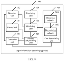
FIG. 7 is a schematic diagram of a depth information obtaining apparatus according to an embodiment of the present invention; -
FIG. 8 is a schematic structural diagram of another depth information obtaining apparatus according to an embodiment of the present invention; and -
FIG. 9 is a schematic structural diagram of an image acquisition device according to an embodiment of the present invention. - The following clearly and completely describes the technical solutions in the embodiments of the present invention with reference to the accompanying drawings in the embodiments of the present invention.
- The embodiments of the present invention disclose a depth information obtaining method and apparatus, and an image acquisition device, so that depth information may be obtained accurately when multiple camera modules perform OIS, thereby implementing focusing accurately and quickly. The following separately provides detailed descriptions.
- To better understand the depth information obtaining method and apparatus, and an image acquisition device according to the embodiments of the present invention, a structure of a camera module applicable to the embodiments of the present invention is first described in the following. Referring to
FIG. 1, FIG. 1 is a schematic structural diagram of a camera module according to an embodiment of the present invention. In the structure shown inFIG. 1 , the camera module includes: ① a protective film, ② a lens group, ③ a focus motor, ④ a light filter, and ⑤ a photosensitive element. The protective film ① is configured to protect the lens group. Thelens group ② generally includes multiple lenses, and has an imaging function. Generally, the lens group has an OIS function. When shaking occurs, a relatively clear image may be obtained by moving the lens (collectively referred to as a lens in the embodiments of the present invention, and also referred to as the lens) of the lens group left and right. Thefocus motor ③ is mainly configured to drive the lens to move for focus assist. Thelight filter ④ is mainly configured to filter infrared rays, making a finally displayed image have a relatively small color difference. Thephotosensitive element ⑤ is mainly configured to convert an image obtained by thelens group ② into an electronic image. A location of the photosensitive element is fixed. For an image acquisition device with multiple camera modules, it may be considered that photosensitive elements corresponding to all cameras are on a same plane. The camera module shown inFIG. 1 may be applied to an image acquisition device with photographing and shooting functions, such as a smartphone, a tablet computer, a personal digital assistant (Personal Digital Assistant, PDA), a mobile Internet device (Mobile Internet Device, MID), and a digital camera. When the image acquisition device includes multiple camera modules, the multiple camera modules are arranged side by side in the image acquisition device. In addition, the multiple camera modules may all have the OIS function, or only one camera has the OIS function. This is not limited in this embodiment of the present invention. - According to the camera module shown in
FIG. 1 , after capturing an image, the image acquisition device may calculate depth information of each shooting object in the image. When focusing needs to be performed on a shooting object, the image acquisition device may perform focusing on the shooting object according to a depth of the shooting object. When the image acquisition device includes the multiple camera modules, images captured by the multiple camera modules are finally fused into one image, so that the captured image is more clear, and can better satisfy a shooting requirement of a user. It should be noted that this solution is proposed on a basis that multiple cameras perform OIS. - Based on the camera module shown in
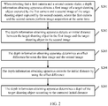
FIG. 1 , an embodiment of the present invention discloses a depth information obtaining method. Referring toFIG. 2, FIG. 2 is a schematic flowchart of the depth information obtaining method according to this embodiment of the present invention. The method shown inFIG. 2 may be applied to an image acquisition device. The image acquisition device includes a first camera and a second camera. As shown inFIG. 2 , the depth information obtaining method may include the following steps. - S201. When detecting that the first camera and the second camera shake, a depth information obtaining apparatus obtains a first image of a target shooting object captured by the first camera and a second image of the target shooting object captured by the second camera, where the first camera and the second camera perform image acquisition at the same time.
- In this embodiment of the present invention, when the image acquisition device enters an image preview screen, the first camera and the second camera capture images in respective fields of view in real time. Generally, the first camera and the second camera shake at the same time. Therefore, when the depth information obtaining apparatus detects that the first camera and the second camera shake (specifically, a gyroscope may be used to detect whether shaking occurs), the first camera and the second camera capture images from a current environment at the same time, and obtain a first image of the first camera and a second image of the second camera respectively, so that the depth information obtaining apparatus obtains the first image and the second image. Both the first image and the second image include a target shooting object. The first image and the second image are electronic images obtained by converting, by photosensitive elements of the first camera and the second camera, images obtained by lenses of the cameras. The target shooting object is any shooting object existing in both the first image and the second image, such as a human face, a building, or an animal. This is not limited in this embodiment of the present invention.
- In this embodiment of the present invention, the first camera includes a first lens, and the second camera includes a second lens. When detecting that the first camera and the second camera shake, in addition to the first image and the second image, the depth information obtaining apparatus obtains a moving distance af_offset1 of the first lens and a moving distance af_offset2 of the second lens.
- Specifically, af_offset1 is a scalar distance between a current location of the first lens and a first start location of the first lens on a Z-axis of a three-dimensional coordinate system, that is, a relative moving distance between the current location at which the first lens captures the first image and the first start location of the first lens. af_offset2 is a scalar distance between a current location of the second lens and a second start location of the second lens on the Z-axis of the three-dimensional coordinate system, that is, a relative moving distance between the current location at which the second lens captures the second image and the second start location of the second lens. The first start location is mainly a location, of the first lens, at which a perpendicular distance between the first lens and the photosensitive element of the first camera is one times a focal length of the first lens. The second start location is mainly a location, of the second lens, at which a perpendicular distance between the second lens and the photosensitive element of the second camera is one times a focal length of the second lens. A minimum distance between the first lens and the photosensitive element of the first camera is generally a distance of one times the focal length of the first lens. A minimum distance between the second camera and the photosensitive element of the second lens is similarly a distance of one times the focal length of the second lens.
- S202. The depth information obtaining apparatus detects an initial distance between the target shooting object in the first image and the target shooting object in the second image.
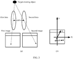
- Also referring to
FIG. 3, FIG. 3 is a schematic diagram of a dual-camera shooting scenario according to an embodiment of the present invention. InFIG. 3 , the depth information obtaining apparatus may create a three-dimensional coordinate system by using a plane on which the photosensitive elements of the cameras are located as an XY-plane and using a direction along which the lenses of the cameras are perpendicular to the photosensitive elements as a Z-axis. A location of an origin of the three-dimensional coordinate system is not limited in this embodiment of the present invention. Therefore, when obtaining the first image captured by the first lens and the second image captured by the second lens (as shown in FIG. (a) ofFIG. 3 ), the depth information obtaining apparatus may make the first image and the second image overlapped and mapped on the XY-plane of the three-dimensional coordinate system (as shown in FIG. (b) ofFIG. 3 ). - Further, when the target shooting object exists in both the first image and the second image, the depth information obtaining apparatus may detect the initial distance between the target shooting object in the first image and the target shooting object in the second image. The initial distance is generally a vector distance and is represented by d0. Specifically, the initial distance is specifically a coordinate distance, obtained by the depth information obtaining apparatus after the depth information obtaining apparatus makes the first image and the second image overlapped and mapped onto the XY-plane, between the target shooting object in the two images (that is, a distance d0 between two black spots in the first image and the second image shown in FIG. (b) of
FIG. 3 ). - Specifically, the initial distance d0 may be a vector distance, obtained by the depth information obtaining apparatus after the depth information obtaining apparatus makes the two images overlapped and mapped onto the XY-plane of the three-dimensional coordinate system, between coordinates of a same characteristic pixel of the target shooting object in the two images. Alternatively, the initial distance d0 may be a distance obtained as follows: On the XY-plane, the depth information obtaining apparatus selects multiple characteristic pixels from the first image; for each of the characteristic pixels, selects, from the second image, a pixel with a same characteristic as the characteristic pixel; calculates a vector distance between coordinates of the two pixels; and finally uses an average value of vector distances of multiple groups of pixels with same characteristics as the initial distance d0 between the target shooting object in the first image and the target shooting object in the second image. This is not limited in this embodiment of the present invention.
- In this embodiment of the present invention, a specific manner of detecting the initial distance between the target shooting object in the first image and the target shooting object in the second image by the depth information obtaining apparatus may be:
detecting the initial distance d0 between the target shooting object in the first image and the target shooting object in the second image that are mapped on the XY-plane of the three-dimensional coordinate system. On the XY-plane of the three-dimensional coordinate system created inFIG. 3 , the depth information obtaining apparatus may first make the first image and the second image overlap with each other; select a characteristic pixel P1 from the target shooting object in the first image, with coordinates, say (P1x,P1y); and select, from the target shooting object in the second image, a pixel P2 with a same characteristic as the characteristic pixel, with coordinates, say (P2x,P2y). In this way, the depth information obtaining apparatus may calculate, according to the coordinates of P1 and P2, the initial vector distance d0, say (d0x,d0y), of the two pixels. d0x may be P1x - P2x or P2x - P1x. When d0x = P1x - P2x, d0y =P1y - P2y; or when d0x = P2x -P1x, d0y = P2y - P1y. This is not limited in this embodiment of the present invention. - Optionally, the depth information obtaining apparatus may further use a central point of the first image in the photosensitive element of the first camera to create a three-dimensional coordinate system; use a central point of the second image in the photosensitive element of the second camera to create another three-dimensional coordinate system; then separately obtain coordinates, in the two coordinate systems, of a same characteristic pixel of the target shooting object in the first image and the target shooting object in the second image; and finally calculate a vector distance between coordinates of the target shooting object in the first image and coordinates of the target shooting object in the second image. The two coordinate systems have a same unit distance and same X-, Y-, and Z-axis directions except different origins of coordinates.
- It should be noted that the depth information obtaining apparatus may create a three-dimensional coordinate system for each of the two cameras, or may create only one three-dimensional coordinate system. This is not limited in this embodiment of the present invention. For ease of description, creating one three-dimensional coordinate system is used for description in this specification. Details are not further described in this embodiment of the present invention.
- S203. The depth information obtaining apparatus determines an offset difference between the first image and the second image.
- In this embodiment of the present invention, the offset difference between the first image and the second image can be understood as a difference between an offset value of the first image and an offset value of the second image. Specifically, after obtaining the first image and the second image, the depth information obtaining apparatus may separately determine coordinates locations of the first image and the second image on the XY-plane of the three-dimensional coordinate system; obtain a coordinates location of a third image captured by the first camera and a coordinates location of a fourth image captured by the second camera, where the coordinates locations are prerecorded when the cameras do not shake; separately calculate a relative coordinates offset, say d1, between the coordinates location of the first image and the coordinates location of the third image, and a relative coordinates offset, say d2, between the coordinates location of the second image and the coordinates location of the fourth image. A difference between d1 and d2 is the offset difference between the first image and the second image. d1, d2, and the offset difference all are vectors.
- In actual application, the offset value d1 is generally a relative vector offset between the first image and an image that is captured by the first lens at the first start location, and the offset value d2 is generally a relative vector offset between the second image and an image that is captured by the second lens at the second start location.
- Specifically, the depth information obtaining apparatus prerecords coordinates of an image, captured by the first lens at one times of a focal length (that is, the first start location) of the first lens, mapped on the XY-plane in the three-dimensional coordinate system (which may be specifically recording a coordinates location of each pixel in the image). When the first camera performs OIS, the first lens moves on the XY-plane of the three-dimensional coordinate system. In this case, a relative offset between the first image captured by the first camera and an image captured at the first start location may occur on the XY-plane. Assuming that coordinates of a pixel at a location in the image captured at the first start location by the first lens are (q1x,q1y), the depth information obtaining apparatus selects, from the first image, a pixel at a same location as the pixel in the image captured at the first start location, with coordinates, say (q'1x,q'1y). The depth information obtaining apparatus may obtain the offset value d1 of the first image, that is, (d1x = q'1x - q1x, d1y = q'1y - q1y), by comparing the coordinates of the two pixels in the two images.
- Similarly, the offset value d2 of the second image may be obtained, that is, (d2x = q'2x - q2x, d2y = q'2y - q2y).
- It can be understood that, if the initial distance d0 is obtained by subtracting the coordinates of the characteristic pixel of the target shooting object in the second image from the coordinates of the same characteristic pixel of the target shooting object in the first image, that is, d0 is (P1x - P2x, P1y - P2y), the offset difference is d1 - d2 . On the contrary, if the initial distance d0 is obtained by subtracting the coordinates of the characteristic pixel of the target shooting object in the first image from the coordinates of the same characteristic pixel of the target shooting object in the second image, that is, d0 is (P2x - P1x, P2y - P1y), the offset difference is d2 - d1 . This is not limited in this embodiment of the present invention. That is, a method for calculating an offset difference needs to be consistent with that for calculating d0.
- It should be noted that, the initial distance may be a relative vector distance between the target shooting object in the first image and the target shooting object in the second image, and the offset difference is a relative offset difference between the offset value of the first image and the offset value of the second image. Alternatively, the initial distance may be a relative vector distance between the target shooting object in the second image and the target shooting object in the first image, and the offset difference is a relative offset difference between the offset value of the second image and the offset value of the first image. This is not limited in this embodiment of the present invention.
- S204. The depth information obtaining apparatus corrects the initial distance by using the offset difference.
- In this embodiment of the present invention, after determining the offset difference between the first image and the second image, the depth information obtaining apparatus may correct d0 by using the offset difference to obtain a corrected distance d0', that is, (d0x', d0y'). Specifically, a specific manner of correcting d0 by the depth information obtaining apparatus is: d0' = d0 - (d1 - d2). That is, d0x' = d0x - (d1x - d2x) and d0y' = d0y - (d1y - d2y).
- S205. The depth information obtaining apparatus determines a depth of the target shooting object according to the corrected initial distance.
- It should be noted that, if shaking occurs, when the cameras perform optical image stabilization, an offset occurs on the lenses on the XY-plane, and a distance between images correspondingly captured changes accordingly.
- In this embodiment of the present invention, when optical image stabilization is not performed, in the images captured by the first camera and the second camera, a distance between the same shooting object in the two images exists. However, an offset does not occur on the lenses on the XY-plane in this case. Therefore, the depth, of each shooting object, obtained by means of calculation according to a depth calculation formula is accurate. However, focal lengths of the first lens and the second lens are slightly different. Therefore, when shaking occurs, either of the first camera or the second camera performs optical image stabilization, offsets of the first lens and the second lens relative to respective start locations on the XY-plane are also different. Assuming that when the first camera and the second camera separately capture an image with the target shooting object, an actual distance between the first lens and the second lens is D0' (as shown in
FIG. 3 ). When optical image stabilization is performed, a difference between the offset of the first lens and that of the second lens on the XY-plane is relatively small, and the depth information apparatus generally cannot directly obtain the actual distance between the two lenses. Therefore, generally, in the prior art, when the depth of the shooting object is calculated, a vector distance between the first start location and the second start location is generally used as an actual vector distance between the first lens and the second lens. As a result, finally obtained depth information is not accurate, or even there is a large difference between the finally obtained depth information and actual depth information. - In this embodiment of the present invention, a focal length of a lens is generally given. Therefore, the depth information obtaining apparatus may generally directly obtain the vector distance D0 between the first start location and the second start location. The vector distance D0 on the XY-plane may be represented as (D0x,D0y). Therefore, the depth information obtaining apparatus may calculate the depth of the target shooting object by using the corrected distance d0 ' and D0. In this way, the finally obtained depth information is relatively accurate.
- It should be noted that D0 may be obtained by subtracting coordinates of the second start location on the XY-plane from coordinates of the first start location on the XY-plane, or may be obtained by subtracting coordinates of the first start location on the XY-plane from coordinates of the second start location on the XY-plane. A method for calculating D0 also needs to be consistent with that for calculating d0. Details are not further described herein in this embodiment of the present invention.
- In this embodiment of the present invention, after obtaining the vector distance D0 between the first start location and the second start location, the corrected distance d0 ', af_offset1, and af_offset2, the depth information obtaining apparatus may calculate the depth of the target shooting object according to the depth calculation formula.
- It can be understood that, when the image acquisition device with multiple camera modules performs shooting or OIS, distances between lenses of all cameras and photosensitive elements need to be equal. Therefore, the depth information obtaining apparatus may calculate an actual depth of the target shooting object according to a parameter of the first camera, or may calculate an actual depth of the target shooting object according to a parameter of the second camera. This is not limited in this embodiment of the present invention. represented by Depth, of the target shooting object may be


- During specific implementation, after correcting the initial distance d0, the depth information apparatus may use the depth calculation formula to calculate a depth of the target shooting object in the first image and a depth of the target shooting object in the second image, where


- Optionally, if both the first camera and the second camera have the OIS function, when the image acquisition device performs OIS, offsets occur on the first lens and the second lens on the XY-plane relative to respective start locations. Therefore, neither the offset value d1 of the first image nor the offset value d2 of the second image is 0. If either of the first camera and the second camera has the OIS function (assuming that the first camera has the OIS function), when the image acquisition device performs OIS, an offset occurs only on the first lens on the XY-plane relative to the start location of the first lens. Therefore, the offset value d1 is not 0, and the offset value d2 of the second image captured by the camera with no OIS function (the second camera) is 0. That is, this solution is not only applicable to an image acquisition device of which two cameras have the OIS function, but also applicable to an image acquisition device of which only one camera has the OIS function. This is not limited in this embodiment of the present invention.
- Optionally, this solution can be not only applicable to an image acquisition device that has two cameras and of which at least one of the cameras has the OIS function, but also applicable to an image acquisition device that has three or more cameras and of which at least one of the cameras has the OIS function. In an image acquisition device with multiple cameras, using an image acquisition device with three cameras as an example, the depth information obtaining apparatus may combine every two of the three cameras, and obtain depths of the target shooting object by using two cameras in each combination, to obtain three depths. Finally, the depth information obtaining apparatus may use an average depth of the three depths as an actual depth of the target shooting object. This is not limited in this depths of the target shooting object by using two cameras in each combination, to obtain three depths. Finally, the depth information obtaining apparatus may use an average depth of the three depths as an actual depth of the target shooting object. This is not limited in this embodiment of the present invention.
- It can be learned that, in the method shown in
FIG. 2 , when detecting that the cameras shake, the depth information obtaining apparatus may obtain the images captured by the first camera and the second camera, detect the initial distance between the target shooting object in the two images, correct the initial distance by using the offset difference between the first image and the second image, and finally substitute the corrected initial distance into the depth calculation formula, to determine the depth of the target shooting object. According to this embodiment of the present invention, when the two cameras may both have an OIS function, or either of the cameras has an OIS function, the depth information obtaining apparatus may correct the distance between the same shooting object in the images obtained by the two cameras, so that depth information, finally obtained according to the corrected distance, of the shooting object is relatively accurate. This can accurately and quickly implement focusing on the shooting object. - Based on the camera module shown in
FIG. 1 , an embodiment of the present invention discloses another depth information obtaining method. Referring toFIG. 4, FIG. 4 is a schematic flowchart of the another depth information obtaining method according to this embodiment of the present invention. The method shown inFIG. 4 may be applied to an image acquisition device. The image acquisition device includes a first camera and a second camera. As shown inFIG. 4 , the depth information obtaining method may include the following steps. - S401. When detecting that the first camera and the second camera shake, a depth information obtaining apparatus obtains a first image of a target shooting object captured by the first camera and a second image of the target shooting object captured by the second camera, where the first camera and the second camera perform image acquisition at the same time.
- S402. The depth information obtaining apparatus detects an initial distance between the target shooting object in the first image and the target shooting object in the second image.
- S403. The depth information obtaining apparatus determines an offset difference between the first image and the second image.
- In this embodiment of the present invention, a specific manner of determining the offset difference between the first image and the second image by the depth information obtaining apparatus may include the following steps.
- (11) When detecting that the first camera and the second camera shake, the depth information obtaining apparatus obtains a first offset of a first lens and a second offset of a second lens.
- (12) The depth information obtaining apparatus determines an offset value of the first image according to the first offset, determines an offset value of the second image according to the second offset, and obtains an offset difference between the offset value of the first image and the offset value of the second image.
- During specific implementation, the first offset of the first lens may be understood as a vector offset between a current location of the first lens and a first start location on the XY-plane, where the vector offset is marked as L1. The second offset of the second lens may be understood as a vector offset between a current location of the second lens and a second start location on the XY-plane, where the vector offset is marked as L2.
- Also referring to
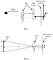
FIG. 5, FIG. 5 is a schematic diagram of a scenario in which a lens moves when a camera performs OIS according to an embodiment of the present invention. As shown inFIG. 5 , a location, represented by a dotted line, of a lens is a start location of the lens, and a location, represented by a solid line, of the lens is a lens location (that is, a current location of the lens) at which the lens captures an image with the target shooting object while performing OIS. In a three-dimensional coordinate system created inFIG. 5 , coordinates of the start location on the XY-plane is subtracted from coordinates of the current location of the lens on the XY-plane to obtain a relative offset L between the lens and the start location, and the offset is a vector. A Z-axis coordinate of the start location is subtracted from a Z-axis coordinate of the current location of the lens to obtain a moving distance af_offset between the lens and the start location. - For example, the first lens is used as an example. The start location shown in
FIG. 5 is a first start location (assuming that coordinates are (L1x, L1y, L1z)) of the first lens, and the current location shown inFIG. 5 is a current location (assuming that coordinates are (L'1x, L'1y, L'1z)) of the first lens. In this case, a moving distance af_offset1 on the Z-axis between the current location of the first lens and the first start location is |L'1z - L1z|, which is a scalar distance. The first offset L1 on the XY-plane between the current location of the first lens and the first start location is (L'1x - L1x, L'1y - L1y), which is a vector distance. - Similarly, a moving distance af_offset2 of the second lens may be obtained, that is |L'2z - L2z|, and the second offset L2 of the second lens may be obtained, that is (L'2x - L2x, L'2y - L2y).
- It should be noted that both the moving distance and the offset of the lens mentioned in this specification refer to a distance between optical centers of the lens (convex lens). Details are not further described in this embodiment of the present invention.
- It should be noted that the depth information obtaining apparatus records offset scales of the first lens and the second lens on the XY-plane by mainly using Hall effect sensors or lasers. In addition to recording the offset scales, offset directions may be recorded. Offsets of the lenses are obtained according to the offset directions of the lenses and distances corresponding to the scales.
- In a feasible implementation, before obtaining the offsets of the first lens and the second lens, the depth information obtaining apparatus may further calibrate a Hall scale. A specific manner may be as follows:
For each camera (a focal length is given, marked as f), the depth information obtaining apparatus may control a lens of the camera to capture a table whose shooting depth is given (marked as S), controls the lens to move along a primary optical axis of the lens. First, the lens is moved one Hall scale, and the table is captured, so that a width (marked as d) of the table on a photosensitive element may be obtained. According to an imaging formula
- In this embodiment of the present invention, after obtaining L1 and L2, the depth information obtaining apparatus can separately calculate the offset value d1 of the first image and the offset value d2 of the second image according to a relationship between an offset of a lens and an offset of an image. A calculation manner is specifically:

- In this embodiment of the present invention, the offsets of the first lens and the second lens are first obtained, and the offset value of the first image and the offset value of the second image are separately calculated according to the foregoing calculation formulas, then an offset difference between the two images are obtained. Therefore, correction of a distance between the target shooting object in the two images is more accurate, thereby improving accuracy of depth information.
- S404. The depth information obtaining apparatus corrects the initial distance by using the offset difference.
- S405. The depth information obtaining apparatus determines a depth of the target shooting object according to the corrected initial distance.
- Optionally, to obtain more accurate depth information, the depth information obtaining apparatus may further calibrate focal lengths of the first lens and the second lens in advance. A specific manner may be as follows:
- Also referring to
FIG. 6, FIG. 6 is a schematic diagram of a focal length calibration method of a lens according to an embodiment of the present invention. As shown inFIG. 6 , the depth information obtaining apparatus may control a lens of the camera to capture a table whose shooting depth is given (marked as S) and whose width is given (marked as D), and control the lens to move along a primary optical axis of the lens. When the lens is moved to a location at which an image has a highest contrast, the table is captured, and a width (marked as d) of the table on the photosensitive element may be obtained. In addition, the depth information obtaining apparatus may obtain a moving distance af_offset of the lens on the Z-axis relative to a start location of the lens. Assuming that a distance between the lens in this case and the photosensitive element is s, where s = f + af_offset, and the following relational expression may be obtained according to the imaging formula of a convex lens and an imaging principle of the lens inFIG. 6 :
- A focal length f of the lens may be calculated according to the foregoing relational expression, that is,

- Therefore, to improve accuracy of depth obtaining, the depth information obtaining apparatus may further calculate a focal length of each camera in this manner.
- In addition, in a production line, a difference between focal lengths of the two cameras may be managed and controlled. A difference between focal lengths, calibrated in the foregoing manner, of the two cameras is set to not greater than a preset focal length threshold. The preset focal length threshold may be 0.01. If the difference is greater than the preset focal length threshold, for example,


- S406. The depth information obtaining apparatus receives an instruction for focusing on the target shooting object.
- In this embodiment of the present invention, the depth information obtaining apparatus may obtain a depth of each shooting object in the foregoing manner of obtaining the depth of the target shooting object Mobile phone photographing is used as an example. When a user needs to perform focusing on a target shooting object, after the user taps the target shooting object on an image preview screen of a mobile phone, the depth information obtaining apparatus may receive an instruction for focusing on the target shooting object. That is, the focusing instruction received by the depth information obtaining apparatus may be triggered by the user, or may be obtained by means of image analysis. This is not limited in this embodiment of the present invention.
- For example, when the mobile phone starts a portrait mode for photographing, after obtaining a depth of each shooting object in a current scenario, the mobile phone may automatically identify that the target shooting object is a person, and an instruction for focusing on the person in the current scenario may be generated. If the user wants to focus on a plant in the background, the user may tap the plant on the image preview screen of the mobile phone, the depth information obtaining apparatus receives an instruction for focusing on the plant.
- S407. In response to the focusing instruction, the depth information obtaining apparatus obtains a first moving distance that is of the first lens and that is corresponding to the depth, and obtains a second moving distance that is of the second lens and that is corresponding to the depth.
- In this embodiment of the present invention, after receiving the focusing instruction, the depth information obtaining apparatus may calculate, according to the obtained depth Depth of the target shooting object, the first moving distance af_offset1' of the first lens on the Z-axis relative to the first start location. Similarly, the depth information obtaining apparatus may obtain the second moving distance af_offset2' of the second lens on the Z-axis relative to the second start location.
- Specifically, with reference to the schematic diagram shown in
FIG. 6 , the depth Depth of the target shooting object is S inFIG. 6 , and f1+af_offset1' is s inFIG. 6 . Therefore, during calculation of the first moving distance af_offset1', an expression for the depth Depth and an expression for s are substituted into an imaging formula, and the first moving distance af_offset1' may be specifically calculated as follows:
- Because f2 +af_offset2' is s in
FIG. 6 , similarly, the second moving distance af_offset2' may be obtained as follows:
- S408. The depth information obtaining apparatus determines a focus location of the first lens according to the first moving distance, determines a focus location of the second lens according to the second moving distance, and controls the first lens and the second lens to move to respective focus locations.
- In this embodiment of the present invention, when focusing needs to be performed on the target shooting object, after determining the first moving distance af_offset1' of the first lens and the second moving distance af_offset2' of the second lens, the depth information obtaining apparatus may determine, according to the first moving distance af_offset1', the focus location at which the first lens performs focusing on the target shooting object; determine, according to the second moving distance af_offset2', the focus location at which the second lens performs focusing on the target shooting object, and control the first lens and the second lens to move to respective focus locations, to implement focusing on the target shooting object.
- Further, when the first lens and the second lens perform focusing on the target shooting object, the depth information obtaining apparatus may further blur another shooting object according to a difference between a depth of the another shooting object and the depth of the target shooting object. Specifically, the depth information obtaining apparatus blurs the another shooting object that is different from the target shooting object (that is, a focus point) by using a blurring algorithm, a shooting object farther away from the target shooting object receives a higher degree of blurring, and a shooting object nearer by the target shooting object receives a lower degree of blurring.
- It can be learned that, in the method shown in
FIG. 4 , the depth information obtaining apparatus may detect the first offset of the first lens on the XY-plane relative to the first start location and the second offset of the second lens on the XY-plane relative to the second start location, to determine the offset value of the first image and the offset value of the second image. In this way, the initial distance between the target shooting object in the first image and the target shooting object in the second image can be corrected more accurately, and the finally calculated depth of the target shooting object is more accurate. Further, according to the depth obtained in this embodiment of the present invention, when focusing is performed on the target shooting object, the depth of the target shooting object is relatively accurate. Therefore, focusing accuracy and a focusing speed of the target shooting object can be increased, and imaging quality of the image acquisition device can be improved. - Based on the camera module shown in
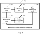
FIG. 1 , an embodiment of the present invention discloses a depth information obtaining apparatus. Referring toFIG. 7, FIG. 7 is a schematic structural diagram of the depth information obtaining apparatus according to this embodiment of the present invention. The depthinformation obtaining apparatus 700 shown inFIG. 7 may be applied to an image acquisition device. The image acquisition device includes a first camera and a second camera. As shown inFIG. 7 , the depthinformation obtaining apparatus 700 may include the following units: - an obtaining
unit 701, configured to: when it is detected that the first camera and the second camera shake, obtain a first image of a target shooting object captured by the first camera and a second image of the target shooting object captured by the second camera, where the first camera and the second camera perform image acquisition at the same time; and - a
detection unit 702, configured to detect an initial distance between the target shooting object in the first image and the target shooting object in the second image; - a first determining
unit 703, configured to determine an offset difference between the first image and the second image; - a
correction unit 704, configured to correct the initial distance by using the offset difference; and - a second determining
unit 705, configured to determine a depth of the target shooting object according to the corrected initial distance. - Optionally, the initial distance may be a relative vector distance between the target shooting object in the first image and the target shooting object in the second image, and the offset difference is a relative offset difference between an offset value of the first image and an offset value of the second image. Alternatively, the initial distance may be a relative vector distance between the target shooting object in the second image and the target shooting object in the first image, and the offset difference is a relative offset difference between the offset value of the second image and the offset value of the first image. This is not limited in this embodiment of the present invention.
- It can be learned that, if both the first camera and the second camera have an OIS function, or either of the cameras has an OIS function, when performing OIS, the depth information obtaining apparatus corrects the distance between the same shooting object in the two images respectively obtained by the two cameras, so that the image acquisition device finally obtains a relatively accurate depth of the object. This improves focusing accuracy of the cameras.
- Also referring to
FIG. 8, FIG. 8 is a schematic structural diagram of another depth information obtaining apparatus according to an embodiment of the present invention. The depthinformation obtaining apparatus 700 shown inFIG. 8 is obtained by means of optimization performed based on the depthinformation obtaining apparatus 700 shown inFIG. 7 . As shown inFIG. 8 , the depthinformation obtaining apparatus 700 may further include the following units. - A receiving
unit 706 is configured to receive an instruction for focusing on the target shooting object. - The obtaining
unit 701 is further configured to: in response to the focusing instruction, obtain a first moving distance that is of a first lens and that is corresponding to the depth, and obtain a second moving distance that is of a second lens and that is corresponding to the depth. - The second determining
unit 705 is further configured to determine a focus location of the first lens according to the first moving distance, and determine a focus location of the second lens according to the second moving distance. - A
control unit 707 is configured to control the first lens and the second lens to move to respective focus locations. - In this embodiment of the present invention, after obtaining the depth of the target shooting object, when needing to perform focusing on the target shooting object, the depth
information obtaining apparatus 700 may obtain distances for which the lenses need to move and that are corresponding to the depth, determine focus locations of the lenses according to respective moving distances, and then move the lenses to the focus locations respectively corresponding to the distances. This can accurately and quickly implement focusing on the target shooting object. - In a feasible implementation, the first determining
unit 703 may include an obtainingsubunit 7031 and a determiningsubunit 7032. - The obtaining
subunit 7031 is configured to: when the depthinformation obtaining apparatus 700 detects that the first camera and the second camera shake, obtain a first offset of the first lens and a second offset of the second lens. - The determining
subunit 7032 is configured to determine an offset value of the first image according to the first offset, and determine an offset value of the second image according to the second offset, to obtain an offset difference between the offset value of the first image and the offset value of the second image. - It can be learned that, in the depth information obtaining apparatuses shown in the
FIG. 7 andFIG. 8 , when detecting that the cameras shake, the depth information obtaining apparatus may obtain the images captured by the first camera and the second camera, detect the initial distance between the target shooting object in the two images, correct the initial distance by using the offset difference between the first image and the second image, and finally substitute the corrected initial distance into a depth calculation formula to determine the depth of the target shooting object. According to this embodiment of the present invention, when the two cameras may both have an OIS function, or either of the cameras has an OIS function, the depth information obtaining apparatus may correct the distance between the same shooting object in the images obtained by the two cameras, so that depth information, finally obtained according to the corrected distance, of the shooting object is relatively accurate. This can accurately and quickly implement focusing on the shooting object. - Based on the camera module shown in
FIG. 1 , an embodiment of the present invention discloses an image acquisition device. Referring toFIG. 9, FIG. 9 is a schematic structural diagram of the image acquisition device according to this embodiment of the present invention. Theimage acquisition device 900 shown inFIG. 9 may include: afirst camera 901, asecond camera 902, at least oneprocessor 903 such as a CPU, areceiver 904, asender 905, adisplay screen 906, and acommunications bus 907. - The
sender 905 is configured to send various data signals such as an image to an external device. - The
display screen 906 is configured to display images captured by thefirst camera 901 and thesecond camera 902. The display screen may be a touch display screen. - The
communications bus 907 is configured to implement communication connections among these components such as thefirst camera 901, thesecond camera 902, theprocessor 903, thereceiver 904, thesender 905, and thedisplay screen 906. - The
first camera 901 is configured to: when theimage acquisition device 900 detects that the first camera and the second camera shake, capture a first image of a target shooting object. - The
second camera 902 is configured to: when theimage acquisition device 900 detects that the first camera and the second camera shake, capture a second image of the target shooting object, where the first camera and the second camera perform image acquisition at the same time. - The
processor 903 is configured to obtain the first image and the second image, and detect an initial distance between the target shooting object in the first image and the target shooting object in the second image. - The
processor 903 is further configured to determine an offset difference between the first image and the second image, and correct the initial distance by using the offset difference. - The
processor 903 is further configured to determine a depth of the target shooting object according to the corrected initial distance. - Optionally, the initial distance may be a relative vector distance between the target shooting object in the first image and the target shooting object in the second image, and the offset difference is a relative offset difference between an offset value of the first image and an offset value of the second image. Alternatively, the initial distance may be a relative vector distance between the target shooting object in the second image and the target shooting object in the first image, and the offset difference is a relative offset difference between the offset value of the second image and the offset value of the first image. This is not limited in this embodiment of the present invention.
- It can be learned that, if both the first camera and the second camera have an OIS function, or either of the cameras has an OIS function, when performing OIS, the
image acquisition device 900 corrects the distance between the same shooting object in the two images respectively obtained by the two cameras, so that the image acquisition device finally obtains a relatively accurate depth of the object. This improves focusing accuracy of the cameras. - In a feasible implementation, a specific manner of determining the offset difference between the first image and the second image by the
processor 903 may be: - when it is detected that the first camera and the second camera shake, obtaining a first offset of a first lens and a second offset of a second lens; and
- determining the offset value of the first image according to the first offset, and determining the offset value of the second image according to the second offset, to obtain an offset difference between the offset value of the first image and the offset value of the second image.
- In another feasible implementation, the
receiver 904 is configured to receive an instruction for focusing on the target shooting object. - The
processor 903 is further configured to: in response to the focusing instruction, obtain a first moving distance that is of the first lens and that is corresponding to the depth, and obtain a second moving distance that is of the second lens and that is corresponding to the depth. - The
processor 903 is further configured to determine a focus location of the first lens according to the first moving distance, and determine a focus location of the second lens according to the second moving distance. - The
processor 903 is further configured to control the first lens and the second lens moving distances, and then move the lenses to the respective focus locations. This can accurately and quickly implement focusing on the target shooting object. - It can be learned that, in the image acquisition device shown in
FIG. 9 , the image acquisition device may include the first camera, the second camera, the processor, and the receiver. When it is detected that the first camera and the second camera shake, the first camera and the second camera may capture the first image and the second image of the target shooting object, respectively. The processor may obtain the first image and the second image, detect the initial distance between the target shooting object in the two images, correct the initial distance by using the offset difference between the first image and the second image, and finally substitute the corrected initial distance into a depth calculation formula, to determine the depth of the target shooting object. According to this embodiment of the present invention, when the two cameras may both have an OIS function, or either of the cameras has an OIS function, the image acquisition device may correct the distance between the same shooting object in the images obtained by the two cameras, so that depth information, finally obtained according to the corrected distance, of the shooting object is relatively accurate. This can accurately and quickly implement focusing on the shooting object. - The units of the embodiments of the present invention may be implemented by using a universal integrated circuit, such as a CPU (Central Processing Unit, central processing unit) or an ASIC (Application Specific Integrated Circuit, application-specific integrated circuit).
- A person of ordinary skill in the art may understand that all or a part of the processes of the methods in the embodiments may be implemented by a computer program instructing relevant hardware. The program may be stored in a computer-readable storage medium. When the program runs, the processes of the methods in the embodiments are performed. The foregoing storage medium may be a magnetic disk, an optical disc, a read-only memory (Read-Only Memory, ROM), or a random access memory (Random Access Memory, RAM).
- The depth information obtaining method and apparatus, and the image acquisition device that are disclosed in the embodiments of the present invention are described in detail in the foregoing. In this specification, specific examples are used to illustrate the principle and implementations of the present invention. The foregoing descriptions of the embodiments are merely intended to help understand the present invention and the core idea of the present invention. In addition, based on the idea of the present invention, a person of ordinary skill in the art can make modifications with respect to the specific implementations and the application scope. In conclusion, the content of this specification shall not be construed as a limitation to the present invention.
Claims (2)
- A depth information obtaining method, for an image acquisition device, wherein the image acquisition device comprises a first camera comprising a first lens and a second camera comprising a second lens, the lenses having slightly different focal lengths, the method comprising:detecting (S201) that the first camera and the second camera shake using a gyroscope common to the first camera and the second camera,obtaining a first image of a target shooting object captured by the first camera and a second image of the target shooting object captured by the second camera, wherein the first camera and the second camera perform image acquisition at the same time;if camera shake is detected:detecting (S202) an initial distance between the target shooting object in the first image and the target shooting object in the second image; by overlapping the first image and the second image and mapping the first and second image to an XY-plane of a three-dimensional coordinate system and identifying a vector distance between a same characteristic pixel of the target shooting object in the first and second imagesdetermining (S203) an offset difference between the first image and the second image; wherein determining (S203) an offset difference comprises: after obtaining the first image and the second image, determining coordinate locations of the first image and the second image on the XY-plane of the three-dimensional coordinate system; obtaining a coordinate location of a third image captured by the first camera and a coordinate location of a fourth image captured by the second camera, where the coordinate locations are prerecorded when the cameras do not shake; calculating a relative coordinates offset d1 between the coordinates location of the first image and the coordinates location of the third image and a relative coordinates offset d2 between the coordinates location of the second image and the coordinates location of the fourth image; and calculating the difference between d1 and d2 as the offset difference between the first image and the second image;correcting (S204) the initial distance by using the offset difference to obtain a correct distance;determining (S205) a depth of the target shooting object according to the corrected initial distance; andfocusing the first camera and the second camera according to the depth of the target shooting object.
- A depth information obtaining apparatus, for an image acquisition device, the image acquisition device including a first camera comprising a first lens and a second camera comprising a second lens, the lenses having slightly different focal lengths, wherein the apparatus comprises:an obtaining unit (701), configured to: detect that the first camera and the second camera shake using a gyroscope common to the first camera and the second camera, obtain a first image of a target shooting object captured by the first camera and a second image of the target shooting object captured by the second camera, wherein the first camera and the second camera perform image acquisition at the same time;a detection unit (702), configured to, if camera shake is detected, detect an initial distance between the target shooting object in the first image and the target shooting object in the second image by overlapping the first image and the second image and mapping the first and second image to an XY-plane of a three-dimensional coordinate system and identifying a vector distance between a same characteristic pixel of the target shooting object in the first and second images;a first determining unit (703), configured to determine an offset difference between the first image and the second image; wherein the first determining unit (703) is configured to determine the offset difference by: after obtaining the first image and the second image, determining coordinate locations of the first image and the second image on the XY-plane of the three-dimensional coordinate system; obtaining a coordinate location of a third image captured by the first camera and a coordinate location of a fourth image captured by the second camera, where the coordinates locations are prerecorded when the cameras do not shake; calculating a relative coordinates offset d1 between the coordinates location of the first image and the coordinates location of the third image and a relative coordinates offset d2 between the coordinates location of the second image and the coordinates location of the fourth image; and calculating the difference between d1 and d2 as the offset difference between the first image and the second image;a correction unit (704), configured to correct the initial distance by using the offset difference to obtain a corrected difference; anda second determining unit (705), configured to determine a depth of the target shooting object according to the corrected initial distance; anda focusing unit configured to focus the first camera and the second camera according to the depth of the target shooting object.
Applications Claiming Priority (1)
| Application Number | Priority Date | Filing Date | Title |
|---|---|---|---|
| PCT/CN2016/070707 WO2017120771A1 (en) | 2016-01-12 | 2016-01-12 | Depth information acquisition method and apparatus, and image collection device |
Publications (3)
| Publication Number | Publication Date |
|---|---|
| EP3389268A1 EP3389268A1 (en) | 2018-10-17 |
| EP3389268A4 EP3389268A4 (en) | 2018-12-19 |
| EP3389268B1 true EP3389268B1 (en) | 2021-05-12 |
Family
ID=59310688
Family Applications (1)
| Application Number | Title | Priority Date | Filing Date |
|---|---|---|---|
| EP16884334.0A Active EP3389268B1 (en) | 2016-01-12 | 2016-01-12 | Depth information acquisition method and apparatus, and image collection device |
Country Status (6)
| Country | Link |
|---|---|
| US (1) | US10506164B2 (en) |
| EP (1) | EP3389268B1 (en) |
| JP (1) | JP6663040B2 (en) |
| KR (1) | KR102143456B1 (en) |
| CN (1) | CN107223330B (en) |
| WO (1) | WO2017120771A1 (en) |
Families Citing this family (19)
| Publication number | Priority date | Publication date | Assignee | Title |
|---|---|---|---|---|
| US20170358101A1 (en) * | 2016-06-10 | 2017-12-14 | Apple Inc. | Optical Image Stabilization for Depth Sensing |
| CN109429004B (en) * | 2017-08-29 | 2021-06-04 | 中兴通讯股份有限公司 | Photographing method and device and mobile terminal |
| CN108154466B (en) * | 2017-12-19 | 2021-12-07 | 北京小米移动软件有限公司 | Image processing method and device |
| US10313654B1 (en) * | 2018-03-19 | 2019-06-04 | Htc Corporation | Image processing method, electronic device, and non-transitory computer readable storage medium |
| CN108769545A (en) * | 2018-06-12 | 2018-11-06 | Oppo(重庆)智能科技有限公司 | A kind of image processing method, image processing apparatus and mobile terminal |
| CN108737735B (en) * | 2018-06-15 | 2019-09-17 | Oppo广东移动通信有限公司 | Method for correcting image, electronic equipment and computer readable storage medium |
| CN108769529B (en) * | 2018-06-15 | 2021-01-15 | Oppo广东移动通信有限公司 | Image correction method, electronic equipment and computer readable storage medium |
| CN108737734B (en) * | 2018-06-15 | 2020-12-01 | Oppo广东移动通信有限公司 | Image compensation method and apparatus, computer-readable storage medium, and electronic device |
| CN108876739B (en) * | 2018-06-15 | 2020-11-24 | Oppo广东移动通信有限公司 | Image compensation method, electronic equipment and computer readable storage medium |
| CN108769528B (en) * | 2018-06-15 | 2020-01-10 | Oppo广东移动通信有限公司 | Image compensation method and apparatus, computer-readable storage medium, and electronic device |
| CN109194945A (en) * | 2018-08-02 | 2019-01-11 | 维沃移动通信有限公司 | A kind of image processing method and terminal |
| CN110830707B (en) * | 2018-08-10 | 2022-01-14 | 华为技术有限公司 | Lens control method and device and terminal |
| CN109714536B (en) * | 2019-01-23 | 2021-02-23 | Oppo广东移动通信有限公司 | Image correction method, image correction device, electronic equipment and computer-readable storage medium |
| US11122248B1 (en) * | 2020-07-20 | 2021-09-14 | Black Sesame International Holding Limited | Stereo vision with weakly aligned heterogeneous cameras |
| WO2022040940A1 (en) * | 2020-08-25 | 2022-03-03 | 深圳市大疆创新科技有限公司 | Calibration method and device, movable platform, and storage medium |
| CN112489116A (en) * | 2020-12-07 | 2021-03-12 | 青岛科美创视智能科技有限公司 | Method and system for estimating target distance by using single camera |
| CN112950691A (en) * | 2021-02-10 | 2021-06-11 | Oppo广东移动通信有限公司 | Control method and device for measuring depth information, electronic equipment and storage medium |
| CN114147727B (en) * | 2022-02-07 | 2022-05-20 | 杭州灵西机器人智能科技有限公司 | Method, device and system for correcting pose of robot |
| CN114554086A (en) * | 2022-02-10 | 2022-05-27 | 支付宝(杭州)信息技术有限公司 | Auxiliary shooting method and device and electronic equipment |
Family Cites Families (16)
| Publication number | Priority date | Publication date | Assignee | Title |
|---|---|---|---|---|
| US7561789B2 (en) * | 2006-06-29 | 2009-07-14 | Eastman Kodak Company | Autofocusing still and video images |
| US8310538B2 (en) * | 2010-03-19 | 2012-11-13 | Fujifilm Corporation | Imaging apparatus, method, program, and recording medium used in the program |
| US20110261166A1 (en) * | 2010-04-21 | 2011-10-27 | Eduardo Olazaran | Real vision 3D, video and photo graphic system |
| US8274552B2 (en) | 2010-12-27 | 2012-09-25 | 3Dmedia Corporation | Primary and auxiliary image capture devices for image processing and related methods |
| US9041791B2 (en) * | 2011-02-01 | 2015-05-26 | Roche Diagnostics Hematology, Inc. | Fast auto-focus in imaging |
| JP5768684B2 (en) | 2011-11-29 | 2015-08-26 | 富士通株式会社 | Stereo image generation apparatus, stereo image generation method, and computer program for stereo image generation |
| JP5948856B2 (en) * | 2011-12-21 | 2016-07-06 | ソニー株式会社 | Imaging apparatus, autofocus method, and program |
| TWI551113B (en) * | 2011-12-27 | 2016-09-21 | 鴻海精密工業股份有限公司 | 3d imaging module and 3d imaging method |
| US20130258044A1 (en) | 2012-03-30 | 2013-10-03 | Zetta Research And Development Llc - Forc Series | Multi-lens camera |
| CN103246130B (en) * | 2013-04-16 | 2016-01-20 | 广东欧珀移动通信有限公司 | A kind of focusing method and device |
| US9210417B2 (en) * | 2013-07-17 | 2015-12-08 | Microsoft Technology Licensing, Llc | Real-time registration of a stereo depth camera array |
| US9524580B2 (en) * | 2014-01-06 | 2016-12-20 | Oculus Vr, Llc | Calibration of virtual reality systems |
| CN104811688B (en) | 2014-01-28 | 2017-09-01 | 聚晶半导体股份有限公司 | Image acquiring device and its image deformation detection method |
| US9247117B2 (en) * | 2014-04-07 | 2016-01-26 | Pelican Imaging Corporation | Systems and methods for correcting for warpage of a sensor array in an array camera module by introducing warpage into a focal plane of a lens stack array |
| CN104093014A (en) | 2014-07-21 | 2014-10-08 | 宇龙计算机通信科技(深圳)有限公司 | Image processing method and image processing device |
| CN104469086B (en) | 2014-12-19 | 2017-06-20 | 北京奇艺世纪科技有限公司 | A kind of video stabilization method and device |
-
2016
- 2016-01-12 JP JP2018554610A patent/JP6663040B2/en active Active
- 2016-01-12 KR KR1020187022702A patent/KR102143456B1/en active IP Right Grant
- 2016-01-12 WO PCT/CN2016/070707 patent/WO2017120771A1/en active Application Filing
- 2016-01-12 US US16/069,523 patent/US10506164B2/en active Active
- 2016-01-12 EP EP16884334.0A patent/EP3389268B1/en active Active
- 2016-01-12 CN CN201680002783.4A patent/CN107223330B/en active Active
Non-Patent Citations (1)
| Title |
|---|
| None * |
Also Published As
| Publication number | Publication date |
|---|---|
| CN107223330A (en) | 2017-09-29 |
| KR102143456B1 (en) | 2020-08-12 |
| EP3389268A1 (en) | 2018-10-17 |
| JP6663040B2 (en) | 2020-03-11 |
| US10506164B2 (en) | 2019-12-10 |
| US20190028646A1 (en) | 2019-01-24 |
| KR20180101466A (en) | 2018-09-12 |
| EP3389268A4 (en) | 2018-12-19 |
| WO2017120771A1 (en) | 2017-07-20 |
| JP2019510234A (en) | 2019-04-11 |
| CN107223330B (en) | 2020-06-26 |
Similar Documents
| Publication | Publication Date | Title |
|---|---|---|
| EP3389268B1 (en) | Depth information acquisition method and apparatus, and image collection device | |
| CN111147741B (en) | Focusing processing-based anti-shake method and device, electronic equipment and storage medium | |
| US9998650B2 (en) | Image processing apparatus and image pickup apparatus for adding blur in an image according to depth map | |
| JP4852591B2 (en) | Stereoscopic image processing apparatus, method, recording medium, and stereoscopic imaging apparatus | |
| US9531938B2 (en) | Image-capturing apparatus | |
| JP6585006B2 (en) | Imaging device and vehicle | |
| EP3073733A1 (en) | Method for generating picture and twin-lens device | |
| CN109712192B (en) | Camera module calibration method and device, electronic equipment and computer readable storage medium | |
| US20180120687A1 (en) | Ranging method, automatic focusing method and device | |
| US20130308005A1 (en) | Image processing apparatus, image processing method, image processing program, and image pickup apparatus | |
| US20170134649A1 (en) | Imaging device and imaging method | |
| US9619886B2 (en) | Image processing apparatus, imaging apparatus, image processing method and program | |
| JP2008241491A (en) | Three-dimensional measurement instrument | |
| WO2014171304A1 (en) | Imaging device, imaging device drive method, and imaging device control program | |
| JPWO2011125937A1 (en) | Calibration data selection device, selection method, selection program, and three-dimensional position measurement device | |
| CN109963080B (en) | Image acquisition method and device, electronic equipment and computer storage medium | |
| EP4016985A1 (en) | Image processing method and apparatus, electronic device, and computer-readable storage medium | |
| US20170310897A1 (en) | Image processing apparatus, imaging apparatus, and image processing method | |
| CN108260360B (en) | Scene depth calculation method and device and terminal | |
| JP5857712B2 (en) | Stereo image generation apparatus, stereo image generation method, and computer program for stereo image generation | |
| US20150281552A1 (en) | Image-capturing apparatus | |
| CN110233969B (en) | Image processing method and device, electronic equipment and computer readable storage medium | |
| CN104811688B (en) | Image acquiring device and its image deformation detection method | |
| WO2016194576A1 (en) | Information processing device and method | |
| JP6486453B2 (en) | Image processing apparatus, image processing method, and program |
Legal Events
| Date | Code | Title | Description |
|---|---|---|---|
| STAA | Information on the status of an ep patent application or granted ep patent |
Free format text: STATUS: THE INTERNATIONAL PUBLICATION HAS BEEN MADE |
|
| PUAI | Public reference made under article 153(3) epc to a published international application that has entered the european phase |
Free format text: ORIGINAL CODE: 0009012 |
|
| STAA | Information on the status of an ep patent application or granted ep patent |
Free format text: STATUS: REQUEST FOR EXAMINATION WAS MADE |
|
| 17P | Request for examination filed |
Effective date: 20180713 |
|
| AK | Designated contracting states |
Kind code of ref document: A1 Designated state(s): AL AT BE BG CH CY CZ DE DK EE ES FI FR GB GR HR HU IE IS IT LI LT LU LV MC MK MT NL NO PL PT RO RS SE SI SK SM TR |
|
| AX | Request for extension of the european patent |
Extension state: BA ME |
|
| A4 | Supplementary search report drawn up and despatched |
Effective date: 20181121 |
|
| RIC1 | Information provided on ipc code assigned before grant |
Ipc: H04N 13/243 20180101ALI20181115BHEP Ipc: H04N 5/232 20060101ALI20181115BHEP Ipc: G06T 7/73 20170101ALI20181115BHEP Ipc: H04N 5/225 20060101ALI20181115BHEP Ipc: H04N 13/246 20180101ALI20181115BHEP Ipc: H04N 13/239 20180101ALI20181115BHEP Ipc: G06T 7/593 20170101ALI20181115BHEP Ipc: G06T 7/80 20170101ALI20181115BHEP Ipc: H04N 17/00 20060101AFI20181115BHEP |
|
| DAV | Request for validation of the european patent (deleted) | ||
| DAX | Request for extension of the european patent (deleted) | ||
| STAA | Information on the status of an ep patent application or granted ep patent |
Free format text: STATUS: EXAMINATION IS IN PROGRESS |
|
| 17Q | First examination report despatched |
Effective date: 20200407 |
|
| GRAP | Despatch of communication of intention to grant a patent |
Free format text: ORIGINAL CODE: EPIDOSNIGR1 |
|
| STAA | Information on the status of an ep patent application or granted ep patent |
Free format text: STATUS: GRANT OF PATENT IS INTENDED |
|
| INTG | Intention to grant announced |
Effective date: 20201203 |
|
| GRAS | Grant fee paid |
Free format text: ORIGINAL CODE: EPIDOSNIGR3 |
|
| GRAA | (expected) grant |
Free format text: ORIGINAL CODE: 0009210 |
|
| STAA | Information on the status of an ep patent application or granted ep patent |
Free format text: STATUS: THE PATENT HAS BEEN GRANTED |
|
| AK | Designated contracting states |
Kind code of ref document: B1 Designated state(s): AL AT BE BG CH CY CZ DE DK EE ES FI FR GB GR HR HU IE IS IT LI LT LU LV MC MK MT NL NO PL PT RO RS SE SI SK SM TR |
|
| REG | Reference to a national code |
Ref country code: GB Ref legal event code: FG4D |
|
| REG | Reference to a national code |
Ref country code: CH Ref legal event code: EP |
|
| REG | Reference to a national code |
Ref country code: DE Ref legal event code: R096 Ref document number: 602016057895 Country of ref document: DE |
|
| REG | Reference to a national code |
Ref country code: IE Ref legal event code: FG4D |
|
| REG | Reference to a national code |
Ref country code: AT Ref legal event code: REF Ref document number: 1392967 Country of ref document: AT Kind code of ref document: T Effective date: 20210615 |
|
| REG | Reference to a national code |
Ref country code: LT Ref legal event code: MG9D |
|
| REG | Reference to a national code |
Ref country code: AT Ref legal event code: MK05 Ref document number: 1392967 Country of ref document: AT Kind code of ref document: T Effective date: 20210512 |
|
| REG | Reference to a national code |
Ref country code: NL Ref legal event code: MP Effective date: 20210512 |
|
| PG25 | Lapsed in a contracting state [announced via postgrant information from national office to epo] |
Ref country code: BG Free format text: LAPSE BECAUSE OF FAILURE TO SUBMIT A TRANSLATION OF THE DESCRIPTION OR TO PAY THE FEE WITHIN THE PRESCRIBED TIME-LIMIT Effective date: 20210812 Ref country code: AT Free format text: LAPSE BECAUSE OF FAILURE TO SUBMIT A TRANSLATION OF THE DESCRIPTION OR TO PAY THE FEE WITHIN THE PRESCRIBED TIME-LIMIT Effective date: 20210512 Ref country code: HR Free format text: LAPSE BECAUSE OF FAILURE TO SUBMIT A TRANSLATION OF THE DESCRIPTION OR TO PAY THE FEE WITHIN THE PRESCRIBED TIME-LIMIT Effective date: 20210512 Ref country code: LT Free format text: LAPSE BECAUSE OF FAILURE TO SUBMIT A TRANSLATION OF THE DESCRIPTION OR TO PAY THE FEE WITHIN THE PRESCRIBED TIME-LIMIT Effective date: 20210512 Ref country code: FI Free format text: LAPSE BECAUSE OF FAILURE TO SUBMIT A TRANSLATION OF THE DESCRIPTION OR TO PAY THE FEE WITHIN THE PRESCRIBED TIME-LIMIT Effective date: 20210512 |
|
| PG25 | Lapsed in a contracting state [announced via postgrant information from national office to epo] |
Ref country code: PL Free format text: LAPSE BECAUSE OF FAILURE TO SUBMIT A TRANSLATION OF THE DESCRIPTION OR TO PAY THE FEE WITHIN THE PRESCRIBED TIME-LIMIT Effective date: 20210512 Ref country code: NO Free format text: LAPSE BECAUSE OF FAILURE TO SUBMIT A TRANSLATION OF THE DESCRIPTION OR TO PAY THE FEE WITHIN THE PRESCRIBED TIME-LIMIT Effective date: 20210812 Ref country code: PT Free format text: LAPSE BECAUSE OF FAILURE TO SUBMIT A TRANSLATION OF THE DESCRIPTION OR TO PAY THE FEE WITHIN THE PRESCRIBED TIME-LIMIT Effective date: 20210913 Ref country code: RS Free format text: LAPSE BECAUSE OF FAILURE TO SUBMIT A TRANSLATION OF THE DESCRIPTION OR TO PAY THE FEE WITHIN THE PRESCRIBED TIME-LIMIT Effective date: 20210512 Ref country code: SE Free format text: LAPSE BECAUSE OF FAILURE TO SUBMIT A TRANSLATION OF THE DESCRIPTION OR TO PAY THE FEE WITHIN THE PRESCRIBED TIME-LIMIT Effective date: 20210512 Ref country code: LV Free format text: LAPSE BECAUSE OF FAILURE TO SUBMIT A TRANSLATION OF THE DESCRIPTION OR TO PAY THE FEE WITHIN THE PRESCRIBED TIME-LIMIT Effective date: 20210512 Ref country code: IS Free format text: LAPSE BECAUSE OF FAILURE TO SUBMIT A TRANSLATION OF THE DESCRIPTION OR TO PAY THE FEE WITHIN THE PRESCRIBED TIME-LIMIT Effective date: 20210912 Ref country code: GR Free format text: LAPSE BECAUSE OF FAILURE TO SUBMIT A TRANSLATION OF THE DESCRIPTION OR TO PAY THE FEE WITHIN THE PRESCRIBED TIME-LIMIT Effective date: 20210813 |
|
| PG25 | Lapsed in a contracting state [announced via postgrant information from national office to epo] |
Ref country code: NL Free format text: LAPSE BECAUSE OF FAILURE TO SUBMIT A TRANSLATION OF THE DESCRIPTION OR TO PAY THE FEE WITHIN THE PRESCRIBED TIME-LIMIT Effective date: 20210512 |
|
| PG25 | Lapsed in a contracting state [announced via postgrant information from national office to epo] |
Ref country code: EE Free format text: LAPSE BECAUSE OF FAILURE TO SUBMIT A TRANSLATION OF THE DESCRIPTION OR TO PAY THE FEE WITHIN THE PRESCRIBED TIME-LIMIT Effective date: 20210512 Ref country code: CZ Free format text: LAPSE BECAUSE OF FAILURE TO SUBMIT A TRANSLATION OF THE DESCRIPTION OR TO PAY THE FEE WITHIN THE PRESCRIBED TIME-LIMIT Effective date: 20210512 Ref country code: DK Free format text: LAPSE BECAUSE OF FAILURE TO SUBMIT A TRANSLATION OF THE DESCRIPTION OR TO PAY THE FEE WITHIN THE PRESCRIBED TIME-LIMIT Effective date: 20210512 Ref country code: RO Free format text: LAPSE BECAUSE OF FAILURE TO SUBMIT A TRANSLATION OF THE DESCRIPTION OR TO PAY THE FEE WITHIN THE PRESCRIBED TIME-LIMIT Effective date: 20210512 Ref country code: ES Free format text: LAPSE BECAUSE OF FAILURE TO SUBMIT A TRANSLATION OF THE DESCRIPTION OR TO PAY THE FEE WITHIN THE PRESCRIBED TIME-LIMIT Effective date: 20210512 Ref country code: SK Free format text: LAPSE BECAUSE OF FAILURE TO SUBMIT A TRANSLATION OF THE DESCRIPTION OR TO PAY THE FEE WITHIN THE PRESCRIBED TIME-LIMIT Effective date: 20210512 Ref country code: SM Free format text: LAPSE BECAUSE OF FAILURE TO SUBMIT A TRANSLATION OF THE DESCRIPTION OR TO PAY THE FEE WITHIN THE PRESCRIBED TIME-LIMIT Effective date: 20210512 |
|
| REG | Reference to a national code |
Ref country code: DE Ref legal event code: R097 Ref document number: 602016057895 Country of ref document: DE |
|
| PLBE | No opposition filed within time limit |
Free format text: ORIGINAL CODE: 0009261 |
|
| STAA | Information on the status of an ep patent application or granted ep patent |
Free format text: STATUS: NO OPPOSITION FILED WITHIN TIME LIMIT |
|
| 26N | No opposition filed |
Effective date: 20220215 |
|
| PG25 | Lapsed in a contracting state [announced via postgrant information from national office to epo] |
Ref country code: IS Free format text: LAPSE BECAUSE OF FAILURE TO SUBMIT A TRANSLATION OF THE DESCRIPTION OR TO PAY THE FEE WITHIN THE PRESCRIBED TIME-LIMIT Effective date: 20210912 Ref country code: AL Free format text: LAPSE BECAUSE OF FAILURE TO SUBMIT A TRANSLATION OF THE DESCRIPTION OR TO PAY THE FEE WITHIN THE PRESCRIBED TIME-LIMIT Effective date: 20210512 |
|
| PG25 | Lapsed in a contracting state [announced via postgrant information from national office to epo] |
Ref country code: IT Free format text: LAPSE BECAUSE OF FAILURE TO SUBMIT A TRANSLATION OF THE DESCRIPTION OR TO PAY THE FEE WITHIN THE PRESCRIBED TIME-LIMIT Effective date: 20210512 |
|
| PG25 | Lapsed in a contracting state [announced via postgrant information from national office to epo] |
Ref country code: MC Free format text: LAPSE BECAUSE OF FAILURE TO SUBMIT A TRANSLATION OF THE DESCRIPTION OR TO PAY THE FEE WITHIN THE PRESCRIBED TIME-LIMIT Effective date: 20210512 |
|
| REG | Reference to a national code |
Ref country code: CH Ref legal event code: PL |
|
| REG | Reference to a national code |
Ref country code: BE Ref legal event code: MM Effective date: 20220131 |
|
| PG25 | Lapsed in a contracting state [announced via postgrant information from national office to epo] |
Ref country code: LU Free format text: LAPSE BECAUSE OF NON-PAYMENT OF DUE FEES Effective date: 20220112 |
|
| PG25 | Lapsed in a contracting state [announced via postgrant information from national office to epo] |
Ref country code: FR Free format text: LAPSE BECAUSE OF NON-PAYMENT OF DUE FEES Effective date: 20220131 Ref country code: BE Free format text: LAPSE BECAUSE OF NON-PAYMENT OF DUE FEES Effective date: 20220131 |
|
| PG25 | Lapsed in a contracting state [announced via postgrant information from national office to epo] |
Ref country code: LI Free format text: LAPSE BECAUSE OF NON-PAYMENT OF DUE FEES Effective date: 20220131 Ref country code: CH Free format text: LAPSE BECAUSE OF NON-PAYMENT OF DUE FEES Effective date: 20220131 |
|
| PG25 | Lapsed in a contracting state [announced via postgrant information from national office to epo] |
Ref country code: IE Free format text: LAPSE BECAUSE OF NON-PAYMENT OF DUE FEES Effective date: 20220112 |
|
| PGFP | Annual fee paid to national office [announced via postgrant information from national office to epo] |
Ref country code: DE Payment date: 20221130 Year of fee payment: 8 |
|
| PGFP | Annual fee paid to national office [announced via postgrant information from national office to epo] |
Ref country code: GB Payment date: 20231130 Year of fee payment: 9 |
|
| PG25 | Lapsed in a contracting state [announced via postgrant information from national office to epo] |
Ref country code: HU Free format text: LAPSE BECAUSE OF FAILURE TO SUBMIT A TRANSLATION OF THE DESCRIPTION OR TO PAY THE FEE WITHIN THE PRESCRIBED TIME-LIMIT; INVALID AB INITIO Effective date: 20160112 |