JP5945992B2 - Shock absorption mechanism - Google Patents
Shock absorption mechanism Download PDFInfo
- Publication number
- JP5945992B2 JP5945992B2 JP2014547028A JP2014547028A JP5945992B2 JP 5945992 B2 JP5945992 B2 JP 5945992B2 JP 2014547028 A JP2014547028 A JP 2014547028A JP 2014547028 A JP2014547028 A JP 2014547028A JP 5945992 B2 JP5945992 B2 JP 5945992B2
- Authority
- JP
- Japan
- Prior art keywords
- wood
- axial direction
- collision load
- crushed
- cylindrical member
- Prior art date
- Legal status (The legal status is an assumption and is not a legal conclusion. Google has not performed a legal analysis and makes no representation as to the accuracy of the status listed.)
- Active
Links
- 230000007246 mechanism Effects 0.000 title claims description 61
- 230000035939 shock Effects 0.000 title claims description 48
- 238000010521 absorption reaction Methods 0.000 title description 18
- 239000002023 wood Substances 0.000 claims description 141
- 230000002787 reinforcement Effects 0.000 description 20
- 230000004048 modification Effects 0.000 description 7
- 238000012986 modification Methods 0.000 description 7
- 239000006096 absorbing agent Substances 0.000 description 3
- 239000011358 absorbing material Substances 0.000 description 3
- 230000009471 action Effects 0.000 description 2
- 229910052782 aluminium Inorganic materials 0.000 description 2
- XAGFODPZIPBFFR-UHFFFAOYSA-N aluminium Chemical compound [Al] XAGFODPZIPBFFR-UHFFFAOYSA-N 0.000 description 2
- 238000000034 method Methods 0.000 description 2
- 230000002093 peripheral effect Effects 0.000 description 2
- 229910000838 Al alloy Inorganic materials 0.000 description 1
- 241000218645 Cedrus Species 0.000 description 1
- 229910000831 Steel Inorganic materials 0.000 description 1
- 230000004323 axial length Effects 0.000 description 1
- 230000008878 coupling Effects 0.000 description 1
- 238000010168 coupling process Methods 0.000 description 1
- 238000005859 coupling reaction Methods 0.000 description 1
- 235000012438 extruded product Nutrition 0.000 description 1
- 229910052751 metal Inorganic materials 0.000 description 1
- 239000002184 metal Substances 0.000 description 1
- 239000006262 metallic foam Substances 0.000 description 1
- 230000000149 penetrating effect Effects 0.000 description 1
- 230000008569 process Effects 0.000 description 1
- 230000004044 response Effects 0.000 description 1
- 239000010959 steel Substances 0.000 description 1
Images


Classifications
-
- B—PERFORMING OPERATIONS; TRANSPORTING
- B60—VEHICLES IN GENERAL
- B60R—VEHICLES, VEHICLE FITTINGS, OR VEHICLE PARTS, NOT OTHERWISE PROVIDED FOR
- B60R19/00—Wheel guards; Radiator guards, e.g. grilles; Obstruction removers; Fittings damping bouncing force in collisions
- B60R19/02—Bumpers, i.e. impact receiving or absorbing members for protecting vehicles or fending off blows from other vehicles or objects
- B60R19/24—Arrangements for mounting bumpers on vehicles
- B60R19/26—Arrangements for mounting bumpers on vehicles comprising yieldable mounting means
- B60R19/34—Arrangements for mounting bumpers on vehicles comprising yieldable mounting means destroyed upon impact, e.g. one-shot type
-
- F—MECHANICAL ENGINEERING; LIGHTING; HEATING; WEAPONS; BLASTING
- F16—ENGINEERING ELEMENTS AND UNITS; GENERAL MEASURES FOR PRODUCING AND MAINTAINING EFFECTIVE FUNCTIONING OF MACHINES OR INSTALLATIONS; THERMAL INSULATION IN GENERAL
- F16F—SPRINGS; SHOCK-ABSORBERS; MEANS FOR DAMPING VIBRATION
- F16F7/00—Vibration-dampers; Shock-absorbers
- F16F7/003—One-shot shock absorbers
-
- F—MECHANICAL ENGINEERING; LIGHTING; HEATING; WEAPONS; BLASTING
- F16—ENGINEERING ELEMENTS AND UNITS; GENERAL MEASURES FOR PRODUCING AND MAINTAINING EFFECTIVE FUNCTIONING OF MACHINES OR INSTALLATIONS; THERMAL INSULATION IN GENERAL
- F16F—SPRINGS; SHOCK-ABSORBERS; MEANS FOR DAMPING VIBRATION
- F16F7/00—Vibration-dampers; Shock-absorbers
- F16F7/12—Vibration-dampers; Shock-absorbers using plastic deformation of members
Landscapes
- Engineering & Computer Science (AREA)
- General Engineering & Computer Science (AREA)
- Mechanical Engineering (AREA)
- Vibration Dampers (AREA)
Description
本発明は、車両衝突時等の衝突荷重を受けてその衝突荷重を吸収できるように構成された衝撃吸収機構に関する。 The present invention relates to an impact absorbing mechanism configured to receive a collision load during a vehicle collision or the like and absorb the collision load.
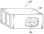
車両前方衝突時等の衝突荷重を受けてその衝突荷重を吸収できるように構成された衝撃吸収部材に関する技術が特開2001−182769号公報に記載されている。特開2001−182769号公報に記載された衝撃吸収部材100は、車両のクラッシュボックス等に使用される衝撃吸収部材であって、図11に示すように、角筒状の金属製中空部材102と、その中空部材102内に充填された木材105とを含む。衝撃吸収部材100は、中空部材102の基端部が車両の左右のサイドメンバ115(図12参照)の先端に固定されており、それらの中空部材102の先端部がフロントバンパ117の背面に固定されている。このため、例えば、車両が前方衝突することで、衝突荷重がフロントバンパ117を介して衝撃吸収部材100に加わると、中空部材102と木材105とが軸方向に潰れることで、前記衝突荷重が吸収されて前記サイドメンバ115に加わる衝突荷重が軽減される。
Japanese Patent Application Laid-Open No. 2001-182769 discloses a technique related to an impact absorbing member configured to receive a collision load at the time of a vehicle front collision or the like and absorb the collision load. An
上記した衝撃吸収部材100の場合、衝突荷重を受けて中空部材102と木材105とが軸方向に潰れた後、前記衝突荷重が解除されると、潰れた木材105が若干復元されて、図12に示すように、軸方向に膨らむ。一方、金属製の中空部材102は潰れた状態からほとんど復元しないため、木材105が軸方向に膨らむことで、中空部材102の先端部と基端部とがそれぞれフロントバンパ117とサイドメンバ115から離れる。これにより、車両の前方衝突後に衝撃吸収部材100がフロントバンパ117とサイドメンバ115との間から外れることがある。前記衝撃吸収部材100がフロントバンパ117とサイドメンバ115との間から外れると、最初の衝突から引き続き次の衝突をした場合に、次の衝突における衝突荷重の吸収効率が低下する。
In the case of the
従って、改良された衝撃吸収部材が求められている。 Accordingly, there is a need for an improved shock absorbing member.
本発明の一つの側面では、衝突荷重を直接的に受ける車両の荷重受け部材と車両の骨格部材との間に設置されて、前記骨格部材に加わる衝突荷重を軽減させる機構であり、前記荷重受け部材を介して加わった衝突荷重を軸方向で受け、軸方向に潰れるように構成された筒状部材と、前記筒状部材に収納されて前記衝突荷重を受けて前記筒状部材と共に軸方向に潰れるように構成されており、前記衝突荷重の解除により潰れた状態から一定量だけ復元方向に膨張可能な木材とを備える衝撃吸収機構であって、前記木材は、年輪の軸心方向が前記筒状部材の軸方向に沿うように、その筒状部材に収納されており、前記衝突荷重を受けたときに前記木材を軸方向から押圧する前記荷重受け部材側の押圧部、もしくは前記骨格部材側の押圧部の少なくとも一方には、潰れる前の前記木材の軸方向における端面が当接する押圧面が設けられ、その押圧面の一部に凹部が形成されており、前記衝突荷重を受けた当初は、前記木材は前記押圧面の凹部以外の部分に押圧されて部分的に潰れ、前記凹部の位置にある前記木材の一部が前記凹部に入り込み、前記木材が前記凹部に入り込んだ後は、前記木材が前記押圧面に押圧されて全体的に潰れる構成である。 One aspect of the present invention is a mechanism that is installed between a vehicle load receiving member that directly receives a collision load and a vehicle skeleton member, and that reduces the collision load applied to the skeleton member. A cylindrical member configured to receive a collision load applied through the member in the axial direction and to be crushed in the axial direction, and to receive the collision load in the cylindrical member in the axial direction together with the cylindrical member An impact absorbing mechanism comprising a wood that is configured to be crushed and expandable in a restoring direction by a certain amount from a crushed state by release of the collision load, wherein the wood has an axial direction of an annual ring that is the cylinder. A pressing portion on the load receiving member side that presses the wood from the axial direction when receiving the collision load, or on the skeleton member side. Less pressing part On the other side, a pressing surface with which the end surface in the axial direction of the wood before being crushed is provided, and a concave portion is formed in a part of the pressing surface. After being pressed by a portion other than the concave portion of the pressing surface and partially crushed, a part of the wood at the position of the concave portion enters the concave portion, and after the wood enters the concave portion, the wood is pressed. It is the structure which is pressed by the surface and is crushed entirely.
本発明の1つの側面においては、衝突荷重を受けた当初は、木材は押圧面の凹部以外の部分に押圧されて部分的に潰れ、前記凹部の位置にある前記木材の一部が前記凹部に入り込み、前記木材が前記凹部に入り込んだ後は、前記木材が全体的に潰れる構成である。そして、衝突荷重が解除されて木材が潰れた状態から一定量だけ復元方向に膨張する。したがって、衝突荷重の解除後、木材の膨張により筒状部材と荷重受け部材間、骨格部材間の接続等が外れても、その木材が凹部に入り込むことで木材及び筒状部材が荷重受け部材と骨格部材との間から外れない。このため、引き続き次の衝突が起こった場合でもその衝突荷重を木材等で受けることができる。 In one aspect of the present invention, at the beginning of receiving a collision load, the wood is pressed by a portion other than the concave portion of the pressing surface and partially crushed, and a part of the wood at the position of the concave portion is in the concave portion. After entering, the wood is crushed as a whole after the wood enters the recess. And it expand | swells in a restoring direction only a fixed amount from the state where the collision load was cancelled | released and the timber was crushed. Therefore, even after the collision load is released, even if the connection between the cylindrical member and the load receiving member, the skeleton member, etc. is disconnected due to the expansion of the wood, the wood and the cylindrical member become the load receiving member by entering the recess. It does not come off between the skeleton members. For this reason, even when the next collision continues, the collision load can be received by wood or the like.
本発明の他の側面においては、衝突荷重を直接的に受ける車両の荷重受け部材と車両の骨格部材との間に設置されて、前記骨格部材に加わる衝突荷重を軽減させる機構であり、前記荷重受け部材を介して加わった衝突荷重を軸方向で受け、軸方向に潰れるように構成された筒状部材と、前記筒状部材に収納されて前記衝突荷重を受けて前記筒状部材と共に軸方向に潰れるように構成されており、前記衝突荷重の解除により潰れた状態から一定量だけ復元方向に膨張可能な木材とを備える衝撃吸収機構であって、前記木材は、年輪の軸心方向が前記筒状部材の軸方向に沿うように、その筒状部材に収納されており、前記衝突荷重を受けたときに前記木材を軸方向から押圧する前記荷重受け部材側の押圧部、もしくは前記骨格部材側の押圧部の少なくとも一方には、前記木材の軸方向における一端部が収納される凹部が形成されて、その凹部内の底面もしくは内側面に前記木材の軸方向における端面が当接する突起が形成されており、前記衝突荷重を受けた当初は、前記木材は凹部の突起に押圧されて部分的に潰れ、前記突起に当接しない前記木材の一部が前記凹部に入り込み、前記木材が前記凹部に入り込んだ後は、前記木材が前記押圧部に押圧されて全体的に潰れる構成である。本発明の他の側面においては、木材の軸方向における一端部が凹部に収納されているため、衝突荷重を受けて木材が潰れる際に、その木材が倒れ難い。また、凹部には、凹部内の底面もしくは内側面に突起が形成されている。このため、木材が潰れる際、木材の軸方向における一端部が突起の働きで径方向外側に膨張し、前記凹部に堅く嵌る。 In another aspect of the present invention, the mechanism is installed between a vehicle load receiving member that directly receives a collision load and a vehicle skeleton member, and reduces the collision load applied to the skeleton member. A cylindrical member configured to receive a collision load applied through the receiving member in the axial direction and to be crushed in the axial direction, and to receive the collision load in the cylindrical member and to receive the collision load in the axial direction An impact absorbing mechanism comprising a wood that can be expanded in a restoring direction by a certain amount from a state of being crushed by releasing the collision load, wherein the wood has an axial direction of an annual ring as described above. The pressing member on the load receiving member side that is housed in the cylindrical member along the axial direction of the cylindrical member and presses the wood from the axial direction when receiving the collision load, or the skeleton member Little pressing part on the side At least one of them is formed with a recess in which one end portion in the axial direction of the wood is stored, and a protrusion with which the end surface in the axial direction of the wood abuts on the bottom surface or the inner side surface in the recess, At the beginning of receiving the collision load, the wood is partially crushed by being pressed by the protrusions of the recesses, and a part of the wood that does not contact the protrusions enters the recesses, and the wood enters the recesses Is a configuration in which the wood is crushed by being pressed by the pressing portion. In another aspect of the present invention, since one end of the wood in the axial direction is housed in the recess, the wood is unlikely to fall when the wood is crushed due to a collision load. In addition, a protrusion is formed on the bottom surface or the inner surface of the recess. For this reason, when the timber is crushed, one end of the timber in the axial direction expands radially outward by the action of the protrusion, and is firmly fitted in the recess.
本発明の他の側面においては、衝突荷重を直接的に受ける車両の荷重受け部材と車両の骨格部材との間に設置されて、前記骨格部材に加わる衝突荷重を軽減させる機構であり、前記荷重受け部材を介して加わった衝突荷重を軸方向で受け、軸方向に潰れるように構成された筒状部材と、前記筒状部材に収納されて前記衝突荷重を受けて前記筒状部材と共に軸方向に潰れるように構成されており、前記衝突荷重の解除により潰れた状態から一定量だけ復元方向に膨張可能な木材とを備える衝撃吸収機構であって、前記木材は、年輪の軸心方向が前記筒状部材の軸方向に沿うように、その筒状部材に収納されており、前記衝突荷重を受けたときに前記木材を軸方向から押圧する前記荷重受け部材側の押圧部、もしくは前記骨格部材側の押圧部の少なくとも一方には、潰れる前の前記木材の軸方向における端面が当接する押圧面が設けられ、その押圧面の裏側に空間が形成されて、前記空間の開口が前記押圧面の一部に設けられており、前記衝突荷重を受けると、前記木材は前記空間の開口以外の部分で前記押圧面に押圧されて部分的に潰れ、前記開口の位置の前記木材がその開口を通過して前記空間に入り込むように構成されている。このため、潰れた木材の一部が開口を通過することでその開口に嵌り、木材及び筒状部材が荷重受け部材と骨格部材との間から外れることがない。また、潰れた木材の一部が開口を通過して空間内に逃げるため、木材が衝突荷重を吸収できない程度にまで潰れ切ることがない。このため、木材は、衝突荷重が加わっている間、継続して潰れることで、前記衝突荷重を吸収できる。 In another aspect of the present invention, the mechanism is installed between a vehicle load receiving member that directly receives a collision load and a vehicle skeleton member, and reduces the collision load applied to the skeleton member. A cylindrical member configured to receive a collision load applied through the receiving member in the axial direction and to be crushed in the axial direction, and to receive the collision load in the cylindrical member and to receive the collision load in the axial direction An impact absorbing mechanism comprising a wood that can be expanded in a restoring direction by a certain amount from a state of being crushed by releasing the collision load, wherein the wood has an axial direction of an annual ring as described above. The pressing member on the load receiving member side that is housed in the cylindrical member along the axial direction of the cylindrical member and presses the wood from the axial direction when receiving the collision load, or the skeleton member Little pressing part on the side At least one side is provided with a pressing surface with which the end surface in the axial direction of the wood before being crushed contacts, a space is formed on the back side of the pressing surface, and an opening of the space is provided in a part of the pressing surface. When the impact load is received, the wood is pressed against the pressing surface at a portion other than the opening of the space and is partially crushed, and the wood at the position of the opening passes through the opening and passes through the space. It is configured to enter. For this reason, a part of the crushed wood passes through the opening and fits into the opening, and the wood and the cylindrical member do not come off between the load receiving member and the skeleton member. In addition, since a part of the crushed wood passes through the opening and escapes into the space, the timber is not crushed to the extent that it cannot absorb the collision load. For this reason, the wood can absorb the collision load by being continuously crushed while the collision load is applied.
本発明の他の側面においては、衝突荷重を直接的に受ける車両の荷重受け部材と車両の骨格部材との間に設置されて、前記骨格部材に加わる衝突荷重を軽減させる機構であり、前記荷重受け部材を介して加わった衝突荷重を軸方向で受け、軸方向に潰れるように構成された筒状部材と、前記筒状部材に収納されて前記衝突荷重を受けて前記筒状部材と共に軸方向に潰れるように構成されており、前記衝突荷重の解除により潰れた状態から一定量だけ復元方向に膨張可能な木材とを備える衝撃吸収機構であって、前記木材は、年輪の軸心方向が前記筒状部材の軸方向に沿うように、その筒状部材に収納されており、前記衝突荷重を受けたときに前記木材を軸方向から押圧する前記荷重受け部材側の押圧部、もしくは前記骨格部材側の押圧部の少なくとも一方には、前記木材の軸方向における一端部が収納される空間が形成されており、前記木材の一端部は、あらかじめ前記空間の一部に収納された状態で連結機構により前記押圧部と連結されており、前記衝突荷重を受けると、前記木材は連結機構を介して押圧されて部分的に潰れ、前記連結機構に当接しない前記木材の一部が前記空間に入り込むように構成されている。即ち、押圧部と木材の一端部とが連結機構により連結されているため、木材及び筒状部材が荷重受け部材と骨格部材との間から外れない。また、木材の一部が空間内に逃げるため、木材が衝突荷重を吸収できない程度にまで潰れ切らない。 In another aspect of the present invention, the mechanism is installed between a vehicle load receiving member that directly receives a collision load and a vehicle skeleton member, and reduces the collision load applied to the skeleton member. A cylindrical member configured to receive a collision load applied through the receiving member in the axial direction and to be crushed in the axial direction, and to receive the collision load in the cylindrical member and to receive the collision load in the axial direction An impact absorbing mechanism comprising a wood that can be expanded in a restoring direction by a certain amount from a state of being crushed by releasing the collision load, wherein the wood has an axial direction of an annual ring as described above. The pressing member on the load receiving member side that is housed in the cylindrical member along the axial direction of the cylindrical member and presses the wood from the axial direction when receiving the collision load, or the skeleton member Little pressing part on the side At least one space is formed in which one end of the wood in the axial direction is stored, and the one end of the wood is stored in advance in a part of the space by the connecting mechanism. When the collision load is received, the wood is pressed through the connection mechanism and partially crushed, and a part of the wood not contacting the connection mechanism enters the space. ing. That is, since the pressing portion and the one end portion of the wood are coupled by the coupling mechanism, the wood and the cylindrical member do not come off between the load receiving member and the skeleton member. In addition, since a part of the wood escapes into the space, the wood is not crushed to the extent that it cannot absorb the collision load.
以下、図1から図6に基づいて本発明の第一実施形態に係る衝撃吸収機構について説明する。ここで、図中に示す前後左右、及び上下は、衝撃吸収機構が取付けられる車両の前後左右、及び上下に対応している。 Hereinafter, the impact absorbing mechanism according to the first embodiment of the present invention will be described with reference to FIGS. Here, the front, rear, left, right, and top and bottom shown in the figure correspond to the front, back, left, right, and top and bottom of the vehicle to which the shock absorbing mechanism is attached.
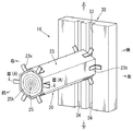
本実施形態に係る衝撃吸収機構10は、車両前方衝突時の衝突荷重Fを受けてその衝突荷重Fを吸収する機構である。衝撃吸収機構10は、図1に示すように、フロントバンパ(図示省略)のバンパーリインフォース3と車両2の左右のサイドメンバ5との間に配置されるクラッシュボックスの部分に取付けられている。前記バンパーリインフォース3は荷重受け部材と呼ばれることもあり、前記サイドメンバ5は車両の骨格部材と呼ばれることもある。衝撃吸収機構10は、図2、図3(A)及び図3(B)に示すように、サイドメンバ5の先端に取付けられた押圧板部30と、衝突荷重Fを吸収する衝撃吸収部20とを含む。
The
押圧板部30は、図3(A)等に示すように、サイドメンバ5の先端で衝撃吸収部20を支えるとともに、前記衝撃吸収部20を介して衝突荷重Fを受ける角形の厚板である。押圧板部30は、その押圧板部30の表面である押圧面32が車両前後方向に対して直角な仮想平面と平行になるように、前記サイドメンバ5の先端に固定されている。押圧板部30の押圧面32には、図3(A)に示すように、上下方向に延びる直線溝34が車幅方向に複数本(図3(A)では2本)形成されている。直線溝34は、断面角形に形成されており、押圧板部30の上端から下端まで連続して設けられている。ここで、前記直線溝34は、厚板状の押圧板部30の押圧面32に切削加工等により形成するのが好ましい。また、直線溝34の開口側を若干狭くするのが好ましい。また、図3(B)に示すように、押圧板部30の押圧面32に上下方向に延びる一対の突条36を設け、突条36間に直線溝34を形成することも可能である。
As shown in FIG. 3A and the like, the
そして、押圧板部30の押圧面32の中央に、図2に示すように、衝撃吸収部20の基端部が複数の直線溝34を跨ぐように固定されている。衝撃吸収部20は押圧板部30の押圧面32から前方に突出するようにその押圧面32に固定されており、その衝撃吸収部20の先端がバンパーリインフォース3の背面に固定されている。
And as shown in FIG. 2, the base end part of the impact-absorbing
衝撃吸収部20は、図2、図3(A)及び図3(B)に示すように、筒状部材23と、その筒状部材23に収納される木材25とを備えており、衝突荷重Fを衝撃吸収部20の軸方向で受けられるように構成されている。即ち、衝撃吸収部20は、その衝撃吸収部20の軸心が押圧板部30の押圧面32に対して直角となるように、その押圧面32に固定される。衝撃吸収部20の筒状部材23は、例えば、アルミ合金を使用した押出成形品であり、図2に示すように、軸心に対して直角な断面が正六角形状に形成されている。なお、筒状部材23は断面四角形、又は正五角形等に成形することも可能である。ここで、筒状部材23の軸方向における長さ寸法は約70mm、幅寸法(六角形の外接円の直径寸法)は約28mm、肉厚寸法は約0.8mm程度に設定されている。
As shown in FIGS. 2, 3 (A) and 3 (B), the
衝撃吸収部20を構成する木材25は、図2、図3(A)及び図3(B)等に示すように、筒状部材23の軸心に対して直角な断面形状(横断面形状)と等しい横断面形状(六角柱形)に形成されており、その筒状部材23の軸方向の長さとほぼ等しい長さ(約70mm)に設定されている。木材25は、年輪25kの軸心方向が長手方向(軸方向)に延びるように六角柱形に成形されている。このため、木材25を筒状部材23に収納した状態で、その木材25の年輪25kの軸心方向が筒状部材23の軸方向とほぼ一致する。即ち、前記木材25は年輪25kの軸心方向が筒状部材23の軸方向に沿うように、その筒状部材23に収納される。このため、木材25の軸心方向の強度が高くなり、その木材によって大きな衝突荷重Fを受けられる。前記木材25としては、例えば、杉材が好適に使用される。ここで、木材25の幅寸法(六角形の外接円の直径寸法)は、木材25の外周面と筒状部材23の内周面間のクリアランスが約0.25mm程度になる値(約28mm)に設定されている。
As shown in FIGS. 2, 3A, 3B, etc., the
衝撃吸収機構10を取付ける場合には、先ず、左右の押圧板部30をそれぞれ左右のサイドメンバ5の先端に固定する。次に、左右の衝撃吸収部20をそれぞれ左右の押圧板部30の押圧面32に固定する。即ち、図3(A)に示すように、衝撃吸収部20を押圧板部30の押圧面32の中央に配置した状態で、その衝撃吸収部20の筒状部材23の後端面と木材25の後端面とを押圧板部30の押圧面32に当接させる。また、図3(B)に示すように、衝撃吸収部20の木材25の後端面を押圧板部30の突条36の先端面に当接させた状態で、筒状部材23の後端面を押圧板部30の押圧面32に当接させる。そして、この状態で、筒状部材23の後端部を、図2に示すように、ブラケット23b等を利用して押圧板部30の押圧面32に固定する。これにより、木材25は、押圧面32に形成された直線溝34を跨ぐように配置される。
When attaching the
次に、左右の筒状部材23の先端面と木材25の先端面とをバンパーリインフォース3の背面に当接させ、筒状部材23の先端部をブラケット23x等によりバンパーリインフォース3の背面に固定する。ここで、押圧板部30、及びバンパーリインフォース3を、例えば、アルミ等で成形する場合には、筒状部材23を直接的に押圧板部30の押圧面32、及びバンパーリインフォース3の背面に溶接することも可能である。
Next, the front end surface of the left and right
次に、図4(A)及び図4(B)に基づいて、前記衝撃吸収機構10の動作について説明する。車両2が前方衝突をし、衝突荷重Fがバンパーリインフォース3に加わると、その衝突荷重Fがバンパーリインフォース3から衝撃吸収部20の筒状部材23と木材25に対して軸方向に加わる。即ち、衝撃吸収部20は、バンパーリインフォース3とサイドメンバ5の押圧板部30の押圧面32とによって軸方向両側から衝突荷重Fと等しい押圧力を受ける。そして、衝突荷重Fが木材25等の許容値を超えた段階で、図4(A)及び図4(B)に示すように、木材25と筒状部材23とが軸方向に潰れる。これにより、衝突荷重Fが木材25と筒状部材23とにより吸収されて、サイドメンバ5に加わる衝突荷重Fが軽減される。このとき、潰れた木材25の一部は押圧板部30の押圧面32に形成された直線溝34に押し込まれる。
Next, based on FIG. 4 (A) and FIG. 4 (B), operation | movement of the said
そして、車両2の移動により衝突荷重Fが解除されると、潰れた木材25が一定量だけ復元方向に膨張する。一方、アルミ製の筒状部材23は、潰れた状態からほとんど復元しないため、木材25が軸方向に膨らむことで、筒状部材23の先端部と基端部とがそれぞれバンパーリインフォース3とサイドメンバ5の押圧板部30から離れる。即ち、筒状部材23は、バンパーリインフォース3とサイドメンバ5の押圧板部30から外れる。しかし、潰れた木材25の一部が押圧板部30の押圧面32の直線溝34に押し込まれているため、潰れた木材25が復元方向に膨張するとその木材25の一部は直線溝34と堅く嵌合する。これにより、衝突荷重Fが解除されても、衝撃吸収部20がバンパーリインフォース3とサイドメンバ5の押圧板部30との間から外れなくなる。したがって、最初の衝突から引き続き次の衝突が発生しても、次の衝突の衝突荷重Fを衝撃吸収部20で受けられる。前記木材25は荷重吸収材と呼ばれることもあり、押圧板部30は押圧部と呼ばれることもある。さらに、押圧面32の直線溝34は凹部と呼ばれることもある。
When the collision load F is released by the movement of the
本実施形態に係る衝撃吸収機構10によると、衝突荷重Fを受けて筒状部材23と木材25(荷重吸収材)が潰れると、その潰れた木材25は、サイドメンバ5側の押圧板部30(押圧部)の直線溝34(凹部)に嵌る。そして、衝突荷重Fが解除されて木材25が潰れた状態から一定量だけ復元方向に膨張することで、木材25はさらに堅く直線溝34に嵌る。したがって、衝突荷重Fの解除後、木材25の膨張により筒状部材23とバンパーリインフォース3、サイドメンバ5間の接続が外れても、その木材25が直線溝34に嵌ることで木材25及び筒状部材23がバンパーリインフォース3とサイドメンバ5との間から外れない。また、衝突荷重Fを受けて木材25が潰れる過程で、その木材25の端面の一部が押圧面32に形成された直線溝34に嵌るため、比較的幅寸法の小さな直線溝34でも木材25を良好に保持できる。
According to the
本実施形態では、押圧板部30(押圧部)の押圧面32に複数の直線溝34(凹部)を縦向きに形成する例を示したが、前記直線溝34を横向きに形成することも可能である。さらに、縦横の直線溝34を格子状に交差させることも可能である。また、直線溝34の代わりに押圧面32に複数の平面円形、あるいは平面多角形の凹部を形成することも可能である。
In the present embodiment, an example in which a plurality of linear grooves 34 (concave portions) are formed vertically on the
さらに、本実施形態では、押圧板部30の押圧面32に切削加工により直線溝34を形成する例を示した。しかし、例えば、鋼板をプレス加工により断面角形の波板状に形成し、その凹部を直線溝34とすることも可能である。
Furthermore, in this embodiment, the example which forms the linear groove |
また、本実施形態では、押圧板部30の押圧面32に潰れた木材25の一部が嵌る直線溝34を形成する例を示した。しかし、図5(A)及び図5(B)に示すように、木材25の軸方向における一端部を収納できるように凹部54を形成することも可能である。このとき、凹部54の中央に突起54tを形成することで、木材25が潰れる際、その木材25の軸方向における一端部が突起54tの働きで径方向外側に変形し、前記凹部54に堅く嵌る。ここで、前記突起54tを、図5(A)に示すように、凹部54の底面中央に形成しても良いし、図5(B)に示すように、凹部54の底面中央にリング状にV字溝54vを形成し、そのV字溝54vの内側に突起54tを形成しても良い。このように、木材25の軸方向における一端部が押圧板部30の押圧面32の凹部54に収納されるため、衝突荷重Fを受けて木材25が潰れる際に、その木材25等が倒れ難い。
Moreover, in this embodiment, the example which forms the linear groove |
また、図6に示すように、木材25と共に筒状部材23の一端部が嵌るような凹部64を押圧板部30の押圧面32に形成することも可能である。
Further, as shown in FIG. 6, it is also possible to form a
さらに、本実施形態では、荷重吸収材として木材25を例示したが、木材25の代わりに金属系の発泡体等を使用することも可能である。
Furthermore, in the present embodiment, the
また、押圧板部30をサイドメンバ5側に設ける例を示したが、バンパーリインフォース3側に設けることも可能である。さらに、サイドメンバ5とバンパーリインフォース3との双方に押圧板部30を設けることも可能である。
Moreover, although the example which provides the
さらに、押圧板部30の押圧面32に複数の凸部を形成し、凸部と凸部との間に潰れた木材25が嵌るようにすることも可能である。
Furthermore, it is also possible to form a plurality of convex portions on the
以下、図7(A)から図10に基づいて本発明の第二実施形態に係る衝撃吸収機構70について説明する。例えば、図4(A)及び(B)に示すように、衝撃吸収部20を構成する木材25が完全に潰れ切った状態では、それ以上木材25に対して衝撃荷重Fが加わっても、その衝撃荷重Fを前記木材25で吸収することは難しい。本実施形態に係る衝撃吸収機構70では、衝撃吸収部20を構成する木材25が完全に潰れ切らないようにして、衝撃荷重Fが加わっている間、木材25が衝撃荷重Fを吸収できるようにすることを目的としている。ここで、本実施形態に係る衝撃吸収機構70において、第一実施形態に係る衝撃吸収機構10と同一の部材については同一符号を付して説明を省略する。
Hereinafter, the
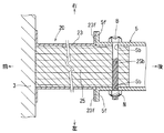
衝撃吸収機構70では、図7(A)に示すように、サイドメンバ5の押圧板部30の中央に角形開口37が形成されており、その角形開口37の奥に潰れた木材25が入り込める空間38が設けられている。角形開口37は、衝撃吸収部20の木材25と同様に、断面正方形に形成されている。そして、角形開口37の断面を構成する正方形の一辺の長さは、木材25の断面を構成する正方形の一辺の長さを、例えば、40mmとした場合に、30mmに設定されている。また、前記空間38は同じく断面正方形状に形成されており、その空間38の正方形を構成する一辺の長さ寸法が角形開口37の一辺の長さ寸法よりも大きな値に設定されている。さらに、衝撃吸収部20を構成する木材25、及び筒状部材23は押圧板部30の角形開口37、及び空間38と軸心を一致させた状態で、同位相となるように、その押圧板部30の押圧面32に固定されている。また、衝撃吸収部20の端面の一部は押圧面32の一部と面接触した状態で固定されている。
In the
これにより、衝突荷重Fがバンパーリインフォース3を介して衝撃吸収部20の筒状部材23と木材25とに軸方向に加わると、図7(B)に示すように、筒状部材23と木材25とが軸方向に潰れるようになる。このとき、木材25の一部は、押圧板部30の角形開口37を通過して空間38に入り込むため、前記木材25が衝撃荷重Fを吸収できない状態まで潰れ切ることがない。このため、衝突荷重Fが加わっている間、木材25は衝撃荷重Fを吸収できる。さらに、潰れた木材25が押圧板部30の角形開口37に嵌るため、衝撃荷重Fが解除されても、衝撃吸収部20がバンパーリインフォース3とサイドメンバ5の押圧板部30間から外れることがない。
Thereby, when the collision load F is applied to the
図8〜図10は変更例に係る衝撃吸収機構70の平断面図を表している。即ち、図8の衝撃吸収機構70では、衝撃吸収部20を構成する木材25、及び筒状部材23の基端部がサイドメンバ5の先端内側に形成された空間5sに挿入されている。サイドメンバ5の先端部と、衝撃吸収部20(木材25、筒状部材23)の基端部とには、所定位置に左右方向に貫通するボルト穴5b、23c、25bが形成されている。そして、前記ボルト穴5b、23c、25bに、例えば、ボルトBが通され、そのボルトBにナットNが締め付けられることで、サイドメンバ5と、そのサイドメンバ5の先端内側に収納された衝撃吸収部20の基端部とが連結される。サイドメンバ5の先端部は押圧部と呼ばれることもあり、ボルトB、ナットN等は連結機構と呼ばれることもある。
8 to 10 are plan sectional views of the
上記構成により、衝撃荷重Fを受けて潰れた木材25の一部はサイドメンバ5の空間5s内に入り込むため、衝撃荷重Fを吸収できない状態まで潰れ切ることがなくなる。また、衝撃吸収部20の基端部がボルトB、ナットNによりサイドメンバ5の先端部に連結されているため、衝撃吸収部20がバンパーリインフォース3とサイドメンバ5間から外れることがない。
With the above configuration, a part of the
ここで、図8では、衝撃吸収部20の木材25と筒状部材23とをサイドメンバ5の先端内側に挿入する例を示したが、図9に示すように、筒状部材23のフランジ部23fをサイドメンバ5の先端フランジ部5fに接続し、サイドメンバ5の先端内側に木材25のみを挿入する構成でも良い。
Here, FIG. 8 shows an example in which the
また、図10に示すように、サイドメンバ5の先端に空間38を有する押圧板部30を固定し、その押圧板部30の空間38に衝撃吸収部20の基端部を収納して、両者20,30をボルトB、ナットNにより連結する構成でも可能である。
Further, as shown in FIG. 10, a
Claims (4)
前記木材は、年輪の軸心方向が前記筒状部材の軸方向に沿うように、その筒状部材に収納されており、
前記衝突荷重を受けたときに前記木材を軸方向から押圧する前記荷重受け部材側の押圧部、もしくは前記骨格部材側の押圧部の少なくとも一方には、潰れる前の前記木材の軸方向における端面が当接する押圧面が設けられ、その押圧面の一部に凹部が形成されており、
前記衝突荷重を受けた当初は、前記木材は前記押圧面の凹部以外の部分に押圧されて部分的に潰れ、前記凹部の位置にある前記木材の一部が前記凹部に入り込み、前記木材が前記凹部に入り込んだ後は、前記木材が前記押圧面に押圧されて全体的に潰れる構成の衝撃吸収機構。A mechanism installed between a vehicle load receiving member that directly receives a collision load and a vehicle skeleton member to reduce a collision load applied to the skeleton member, and a collision load applied via the load receiving member A cylindrical member configured to be crushed in the axial direction, and is configured to be crushed in the axial direction together with the cylindrical member by receiving the collision load stored in the cylindrical member, A shock absorbing mechanism comprising a wood that can expand in a restoring direction by a certain amount from a state of being crushed by releasing the collision load,
The wood is stored in the cylindrical member such that the axial direction of the annual ring is along the axial direction of the cylindrical member,
At least one of the pressing portion on the load receiving member side that presses the wood from the axial direction when receiving the collision load or the pressing portion on the skeleton member side has an end surface in the axial direction of the wood before being crushed. A pressing surface to be in contact is provided, and a recess is formed in a part of the pressing surface,
At the beginning of receiving the collision load, the wood is pressed by a portion other than the concave portion of the pressing surface and is partially crushed, a part of the wood at the position of the concave portion enters the concave portion, and the wood is An impact absorbing mechanism configured such that after entering the recess, the wood is pressed against the pressing surface and crushed entirely.
前記木材は、年輪の軸心方向が前記筒状部材の軸方向に沿うように、その筒状部材に収納されており、
前記衝突荷重を受けたときに前記木材を軸方向から押圧する前記荷重受け部材側の押圧部、もしくは前記骨格部材側の押圧部の少なくとも一方には、前記木材の軸方向における一端部が収納される凹部が形成されて、その凹部内の底面もしくは内側面に前記木材の軸方向における端面が当接する突起が形成されており、
前記衝突荷重を受けた当初は、前記木材は凹部の突起に押圧されて部分的に潰れ、前記突起に当接しない前記木材の一部が前記凹部に入り込み、前記木材が前記凹部に入り込んだ後は、前記木材が前記押圧部に押圧されて全体的に潰れる構成の衝撃吸収機構。A mechanism installed between a vehicle load receiving member that directly receives a collision load and a vehicle skeleton member to reduce a collision load applied to the skeleton member, and a collision load applied via the load receiving member A cylindrical member configured to be crushed in the axial direction, and is configured to be crushed in the axial direction together with the cylindrical member by receiving the collision load stored in the cylindrical member, A shock absorbing mechanism comprising a wood that can expand in a restoring direction by a certain amount from a state of being crushed by releasing the collision load,
The wood is stored in the cylindrical member such that the axial direction of the annual ring is along the axial direction of the cylindrical member,
One end portion in the axial direction of the wood is accommodated in at least one of the pressing portion on the load receiving member side that presses the wood from the axial direction when receiving the collision load, or the pressing portion on the skeleton member side. A protrusion is formed on the bottom surface or the inner side surface of the recess, and the end face in the axial direction of the wood abuts.
At the beginning of receiving the collision load, the wood is partially crushed by being pressed by the protrusions of the recesses, and a part of the wood that does not contact the protrusions enters the recesses, and the wood enters the recesses Is an impact absorbing mechanism configured such that the wood is crushed by being pressed by the pressing portion.
前記木材は、年輪の軸心方向が前記筒状部材の軸方向に沿うように、その筒状部材に収納されており、
前記衝突荷重を受けたときに前記木材を軸方向から押圧する前記荷重受け部材側の押圧部、もしくは前記骨格部材側の押圧部の少なくとも一方には、潰れる前の前記木材の軸方向における端面が当接する押圧面が設けられ、その押圧面の裏側に空間が形成されて、前記空間の開口が前記押圧面の一部に設けられており、
前記衝突荷重を受けると、前記木材は前記空間の開口以外の部分で前記押圧面に押圧されて部分的に潰れ、前記開口の位置の前記木材がその開口を通過して前記空間に入り込むように構成されている衝撃吸収機構。A mechanism installed between a vehicle load receiving member that directly receives a collision load and a vehicle skeleton member to reduce a collision load applied to the skeleton member, and a collision load applied via the load receiving member A cylindrical member configured to be crushed in the axial direction, and is configured to be crushed in the axial direction together with the cylindrical member by receiving the collision load stored in the cylindrical member, A shock absorbing mechanism comprising a wood that can expand in a restoring direction by a certain amount from a state of being crushed by releasing the collision load,
The wood is stored in the cylindrical member such that the axial direction of the annual ring is along the axial direction of the cylindrical member,
At least one of the pressing portion on the load receiving member side that presses the wood from the axial direction when receiving the collision load or the pressing portion on the skeleton member side has an end surface in the axial direction of the wood before being crushed. A pressing surface to contact, a space is formed on the back side of the pressing surface, an opening of the space is provided in a part of the pressing surface;
When the impact load is received, the wood is pressed against the pressing surface at a portion other than the opening of the space and is partially crushed, so that the wood at the position of the opening passes through the opening and enters the space. Configured shock absorbing mechanism.
前記木材は、年輪の軸心方向が前記筒状部材の軸方向に沿うように、その筒状部材に収納されており、
前記衝突荷重を受けたときに前記木材を軸方向から押圧する前記荷重受け部材側の押圧部、もしくは前記骨格部材側の押圧部の少なくとも一方には、前記木材の軸方向における一端部が収納される空間が形成されており、
前記木材の一端部は、あらかじめ前記空間の一部に収納された状態で連結機構により前記押圧部と連結されており、
前記衝突荷重を受けると、前記木材は連結機構を介して押圧されて部分的に潰れ、前記連結機構に当接しない前記木材の一部が前記空間に入り込むように構成されている衝撃吸収機構。A mechanism installed between a vehicle load receiving member that directly receives a collision load and a vehicle skeleton member to reduce a collision load applied to the skeleton member, and a collision load applied via the load receiving member A cylindrical member configured to be crushed in the axial direction, and is configured to be crushed in the axial direction together with the cylindrical member by receiving the collision load stored in the cylindrical member, A shock absorbing mechanism comprising a wood that can expand in a restoring direction by a certain amount from a state of being crushed by releasing the collision load,
The wood is stored in the cylindrical member such that the axial direction of the annual ring is along the axial direction of the cylindrical member,
One end portion in the axial direction of the wood is accommodated in at least one of the pressing portion on the load receiving member side that presses the wood from the axial direction when receiving the collision load, or the pressing portion on the skeleton member side. Space is formed,
One end of the wood is connected to the pressing portion by a connecting mechanism in a state of being stored in a part of the space in advance.
An impact absorbing mechanism configured such that when the impact load is received, the wood is pressed and partially crushed through a connection mechanism, and a part of the wood not contacting the connection mechanism enters the space.
Applications Claiming Priority (3)
| Application Number | Priority Date | Filing Date | Title |
|---|---|---|---|
| JP2012253209 | 2012-11-19 | ||
| JP2012253209 | 2012-11-19 | ||
| PCT/JP2013/080780 WO2014077314A1 (en) | 2012-11-19 | 2013-11-14 | Shock absorbing mechanism |
Publications (2)
| Publication Number | Publication Date |
|---|---|
| JP5945992B2 true JP5945992B2 (en) | 2016-07-05 |
| JPWO2014077314A1 JPWO2014077314A1 (en) | 2017-01-05 |
Family
ID=50731223
Family Applications (1)
| Application Number | Title | Priority Date | Filing Date |
|---|---|---|---|
| JP2014547028A Active JP5945992B2 (en) | 2012-11-19 | 2013-11-14 | Shock absorption mechanism |
Country Status (5)
| Country | Link |
|---|---|
| US (1) | US9669787B2 (en) |
| EP (1) | EP2921354B1 (en) |
| JP (1) | JP5945992B2 (en) |
| CN (1) | CN104968535B (en) |
| WO (1) | WO2014077314A1 (en) |
Cited By (1)
| Publication number | Priority date | Publication date | Assignee | Title |
|---|---|---|---|---|
| JP2019189013A (en) * | 2018-04-25 | 2019-10-31 | トヨタ車体株式会社 | Impact absorption member and method for manufacture thereof |
Families Citing this family (23)
| Publication number | Priority date | Publication date | Assignee | Title |
|---|---|---|---|---|
| JP6398853B2 (en) * | 2015-04-13 | 2018-10-03 | トヨタ車体株式会社 | Shock absorbing member |
| ITUB20150146A1 (en) * | 2015-05-13 | 2016-11-13 | Fca Italy Spa | STRUCTURE OF THE END OF A MOTOR VEHICLE BODY |
| JP6354677B2 (en) * | 2015-06-25 | 2018-07-11 | トヨタ車体株式会社 | Vehicle shock absorption structure |
| JP6228180B2 (en) * | 2015-12-01 | 2017-11-08 | 本田技研工業株式会社 | Body front structure |
| US9902349B2 (en) * | 2016-03-22 | 2018-02-27 | Ford Global Technologies, Llc | Vehicle bumper assembly |
| US11414300B2 (en) * | 2016-04-14 | 2022-08-16 | Mitsubishi Electric Corporation | Damper for elevator, and elevator |
| JP6846081B2 (en) * | 2016-11-30 | 2021-03-24 | トヨタ車体株式会社 | Vehicle parts |
| JP6677201B2 (en) * | 2017-03-23 | 2020-04-08 | トヨタ車体株式会社 | Vehicle shock absorber |
| JP6798457B2 (en) * | 2017-09-15 | 2020-12-09 | トヨタ自動車株式会社 | Vampari Information |
| JP6729528B2 (en) * | 2017-09-25 | 2020-07-22 | トヨタ車体株式会社 | Impact absorbing member and manufacturing method thereof |
| JP6863219B2 (en) * | 2017-10-13 | 2021-04-21 | トヨタ自動車株式会社 | Vehicle side structure |
| JP6796244B2 (en) * | 2017-11-15 | 2020-12-09 | トヨタ車体株式会社 | Vehicle shock absorber |
| JP7130531B2 (en) * | 2017-12-15 | 2022-09-05 | 株式会社豊田中央研究所 | Shock absorption mechanism |
| US20190264769A1 (en) * | 2018-02-27 | 2019-08-29 | GM Global Technology Operations LLC | Composite energy-absorbing assembly having discrete energy-absorbing elements supported by a carrier plate |
| US11077812B2 (en) | 2018-02-27 | 2021-08-03 | GM Global Technology Operations LLC | Composite energy-absorbing assembly |
| JP6999448B2 (en) * | 2018-02-28 | 2022-01-18 | 株式会社豊田中央研究所 | Impact absorption mechanism |
| JP7089412B2 (en) * | 2018-06-15 | 2022-06-22 | 株式会社豊田中央研究所 | Shock absorption mechanism |
| JP6827973B2 (en) * | 2018-06-15 | 2021-02-10 | 株式会社豊田中央研究所 | Shock absorption mechanism |
| JP7111590B2 (en) * | 2018-11-26 | 2022-08-02 | 株式会社豊田中央研究所 | Shock absorption mechanism |
| JP7191710B2 (en) * | 2019-01-28 | 2022-12-19 | 株式会社豊田中央研究所 | Shock absorption mechanism |
| JP7125826B2 (en) * | 2019-02-18 | 2022-08-25 | トヨタ車体株式会社 | Impact absorbing member and manufacturing method thereof |
| JP7325353B2 (en) * | 2020-02-12 | 2023-08-14 | 株式会社豊田中央研究所 | Shock absorption mechanism |
| US11453284B2 (en) | 2020-06-30 | 2022-09-27 | GM Global Technology Operations LLC | Lightweight, single-piece energy absorbing and intrusion resistant battery tray for a vehicle |
Citations (7)
| Publication number | Priority date | Publication date | Assignee | Title |
|---|---|---|---|---|
| JPH06171443A (en) * | 1992-12-04 | 1994-06-21 | Nissan Motor Co Ltd | Mounting structure of bumper for vehicle |
| JP2001182769A (en) * | 1999-12-27 | 2001-07-06 | Showa Alum Corp | Shock-absorbing member |
| JP2002513894A (en) * | 1998-05-07 | 2002-05-14 | エミテク・ゲゼルシャフト・フュール・エミシオーンテクノロギー・ミット・ベシュレンクテル・ハフツング | Support structure with deformable elements with reduced residual block length |
| JP2004322861A (en) * | 2003-03-04 | 2004-11-18 | Jsp Corp | Bumper structure |
| JP2005162061A (en) * | 2003-12-03 | 2005-06-23 | Mitsubishi Alum Co Ltd | Shock absorbing member for vehicle |
| JP2012132552A (en) * | 2010-12-01 | 2012-07-12 | Toyota Auto Body Co Ltd | Shock absorbing member |
| JP2012218712A (en) * | 2011-04-14 | 2012-11-12 | Toyota Auto Body Co Ltd | Impact absorbing member |
Family Cites Families (5)
| Publication number | Priority date | Publication date | Assignee | Title |
|---|---|---|---|---|
| US3797873A (en) * | 1971-06-28 | 1974-03-19 | Ethyl Corp | Energy absorbing apparatus |
| US4652032A (en) * | 1985-10-16 | 1987-03-24 | Borg-Warner Chemicals, Inc. | Vehicle bumper assembly |
| DE19616944B4 (en) * | 1996-04-27 | 2006-05-18 | Suspa Holding Gmbh | impact attenuator |
| US5875875A (en) * | 1996-11-05 | 1999-03-02 | Knotts; Stephen Eric | Shock isolator and absorber apparatus |
| ITMI20060970A1 (en) * | 2006-05-17 | 2006-08-16 | Adlev Srl | BUMPER COMPLEX FOR VEHICLE AND ITS VEHICLE INCLUDING SUCH BUMPER COMPLEX |
-
2013
- 2013-11-14 JP JP2014547028A patent/JP5945992B2/en active Active
- 2013-11-14 CN CN201380059496.3A patent/CN104968535B/en active Active
- 2013-11-14 EP EP13855601.4A patent/EP2921354B1/en active Active
- 2013-11-14 US US14/442,331 patent/US9669787B2/en active Active
- 2013-11-14 WO PCT/JP2013/080780 patent/WO2014077314A1/en active Application Filing
Patent Citations (7)
| Publication number | Priority date | Publication date | Assignee | Title |
|---|---|---|---|---|
| JPH06171443A (en) * | 1992-12-04 | 1994-06-21 | Nissan Motor Co Ltd | Mounting structure of bumper for vehicle |
| JP2002513894A (en) * | 1998-05-07 | 2002-05-14 | エミテク・ゲゼルシャフト・フュール・エミシオーンテクノロギー・ミット・ベシュレンクテル・ハフツング | Support structure with deformable elements with reduced residual block length |
| JP2001182769A (en) * | 1999-12-27 | 2001-07-06 | Showa Alum Corp | Shock-absorbing member |
| JP2004322861A (en) * | 2003-03-04 | 2004-11-18 | Jsp Corp | Bumper structure |
| JP2005162061A (en) * | 2003-12-03 | 2005-06-23 | Mitsubishi Alum Co Ltd | Shock absorbing member for vehicle |
| JP2012132552A (en) * | 2010-12-01 | 2012-07-12 | Toyota Auto Body Co Ltd | Shock absorbing member |
| JP2012218712A (en) * | 2011-04-14 | 2012-11-12 | Toyota Auto Body Co Ltd | Impact absorbing member |
Cited By (3)
| Publication number | Priority date | Publication date | Assignee | Title |
|---|---|---|---|---|
| JP2019189013A (en) * | 2018-04-25 | 2019-10-31 | トヨタ車体株式会社 | Impact absorption member and method for manufacture thereof |
| WO2019207936A1 (en) * | 2018-04-25 | 2019-10-31 | トヨタ車体株式会社 | Shock-absorbing member and method of manufacturing same |
| US12012060B2 (en) | 2018-04-25 | 2024-06-18 | Toyota Shatal Kabushiki Kaisha | Shock-absorbing member and manufacturing method thereof |
Also Published As
| Publication number | Publication date |
|---|---|
| US9669787B2 (en) | 2017-06-06 |
| JPWO2014077314A1 (en) | 2017-01-05 |
| CN104968535B (en) | 2017-03-08 |
| CN104968535A (en) | 2015-10-07 |
| EP2921354A4 (en) | 2017-02-08 |
| EP2921354A1 (en) | 2015-09-23 |
| US20160272137A1 (en) | 2016-09-22 |
| EP2921354B1 (en) | 2023-06-28 |
| WO2014077314A1 (en) | 2014-05-22 |
Similar Documents
| Publication | Publication Date | Title |
|---|---|---|
| JP5945992B2 (en) | Shock absorption mechanism | |
| JP5545259B2 (en) | Shock absorbing member | |
| JP6354677B2 (en) | Vehicle shock absorption structure | |
| WO2013164931A1 (en) | Impact absorption mechanism | |
| US7810868B2 (en) | Motor vehicle frame structure and crashbox therefor | |
| JP6677201B2 (en) | Vehicle shock absorber | |
| JP5097396B2 (en) | Vehicle structural elements that act to absorb specific impacts by plastic deformation | |
| KR101134946B1 (en) | A mounting method of bumper beam | |
| JP6308194B2 (en) | Vehicle energy absorption structure | |
| WO2012140803A1 (en) | Impact absorption member | |
| WO2013161339A1 (en) | Impact-absorbing structure | |
| JP2012035691A (en) | Towing hook mounting structure of vehicle | |
| JP2007015626A (en) | Support structure for vehicle bumper | |
| JP2015182560A (en) | Vehicle shock absorption structure | |
| JP5522191B2 (en) | Vehicle shock absorption structure | |
| JP2010158954A (en) | Impact absorbing device for vehicle | |
| JP2013141936A (en) | Impact absorbing structure for vehicle | |
| JP4802485B2 (en) | Shock absorbing member connection structure | |
| US20200406844A1 (en) | Structural member for vehicle | |
| JP2006176093A (en) | Bumper and impact absorption structure for vehicle | |
| JP5092680B2 (en) | Body front structure | |
| JP2021084497A (en) | Shock absorbing member for vehicle | |
| CN220262715U (en) | High-stability rear anti-collision beam for van | |
| WO2013080864A1 (en) | Shock-absorbing structure for vehicle | |
| JP2012011796A (en) | Energy absorbing member for vehicle |
Legal Events
| Date | Code | Title | Description |
|---|---|---|---|
| TRDD | Decision of grant or rejection written | ||
| A01 | Written decision to grant a patent or to grant a registration (utility model) |
Free format text: JAPANESE INTERMEDIATE CODE: A01 Effective date: 20160506 |
|
| A61 | First payment of annual fees (during grant procedure) |
Free format text: JAPANESE INTERMEDIATE CODE: A61 Effective date: 20160519 |
|
| R150 | Certificate of patent or registration of utility model |
Ref document number: 5945992 Country of ref document: JP Free format text: JAPANESE INTERMEDIATE CODE: R150 |
|
| R250 | Receipt of annual fees |
Free format text: JAPANESE INTERMEDIATE CODE: R250 |
|
| R250 | Receipt of annual fees |
Free format text: JAPANESE INTERMEDIATE CODE: R250 |
|
| R250 | Receipt of annual fees |
Free format text: JAPANESE INTERMEDIATE CODE: R250 |
|
| R250 | Receipt of annual fees |
Free format text: JAPANESE INTERMEDIATE CODE: R250 |
|
| R250 | Receipt of annual fees |
Free format text: JAPANESE INTERMEDIATE CODE: R250 |
|
| R250 | Receipt of annual fees |
Free format text: JAPANESE INTERMEDIATE CODE: R250 |