JP5932385B2 - Brake control device for man-powered vehicle and man-powered vehicle - Google Patents
Brake control device for man-powered vehicle and man-powered vehicle Download PDFInfo
- Publication number
- JP5932385B2 JP5932385B2 JP2012034293A JP2012034293A JP5932385B2 JP 5932385 B2 JP5932385 B2 JP 5932385B2 JP 2012034293 A JP2012034293 A JP 2012034293A JP 2012034293 A JP2012034293 A JP 2012034293A JP 5932385 B2 JP5932385 B2 JP 5932385B2
- Authority
- JP
- Japan
- Prior art keywords
- brake
- human
- vehicle
- powered vehicle
- drive wheel
- Prior art date
- Legal status (The legal status is an assumption and is not a legal conclusion. Google has not performed a legal analysis and makes no representation as to the accuracy of the status listed.)
- Active
Links
Images


Description
本発明は、人力駆動車のブレーキ制御装置及び人力駆動車に関し、ブレーキにより制動を掛ける人力駆動車のブレーキ制御装置及び人力駆動車に関する。 The present invention relates to a brake control device and a human-powered vehicle for a manpower-driven vehicle, and more particularly to a brake control device and a manpower-driven vehicle for a manpower-driven vehicle that apply braking by a brake.
人力で駆動する車椅子、ベビーカー、三輪車、自転車等の人力駆動車が一般的に使用されている。人力駆動車のうちの車椅子は、通常、前輪と後輪の4輪を有し使用者が座席に座った状態で手により操作可能な位置に後輪を備え、この後輪を駆動輪としている。使用者は手によりこの駆動輪に付いたハンドリムを前後に押すことで駆動輪を回転させて車椅子を前後に動かす。また、車椅子はブレーキを備えこのブレーキにより制動を掛ける。 Human-powered vehicles such as wheelchairs, strollers, tricycles, and bicycles that are driven by human power are generally used. A wheelchair of a man-powered vehicle usually has four wheels, a front wheel and a rear wheel, with a rear wheel at a position where a user can operate by hand while sitting on a seat, and this rear wheel is used as a driving wheel. . The user moves the wheelchair back and forth by rotating the drive wheel by pushing the hand rim attached to the drive wheel back and forth by hand. In addition, the wheelchair is equipped with a brake and brakes are applied by this brake.
この種の車椅子の一例が特許文献1に開示されている。特許文献1に開示の車椅子は、車椅子が予め定めた速度(例えば7km/h)を越えると、ブレーキパッドが車椅子の後輪を強く押し付けて車椅子を停止するようにしている。このため、車椅子は予め定めた速度を越えると急激に減速し停止する。
An example of this type of wheelchair is disclosed in
また、特許文献2に開示されている車椅子のブレーキ装置は、ロッドと、回動部材と、ブレーキ部材と、回転カムとを備える。ロッドの先端部に回動部材を回動可能に取り付け、その先端部にブレーキ部材を取り付ける。そして、回転カムによりロッドを前進させ、車椅子の車輪のタイヤにブレーキ部材を押し付けることにより制動を掛ける。
Moreover, the brake device of the wheelchair currently disclosed by
また、特許文献3に開示されている手動式車椅子のブレーキ装置は、油圧式ブレーキと、油圧式ブレーキに圧力油を供給する油圧ポンプを作動させる電動モータと、電動モータを制御する制御器とを備える。車椅子に制動を掛ける場合、制御器は電動モータをオンにし、油圧ポンプを作動させて圧力油を油圧式ブレーキに供給する。このことにより両主輪(後輪)に油圧式ブレーキにより制動力が掛かる。
A brake device for a manual wheelchair disclosed in
上述した特許文献1に記載の車椅子は、予め定めた速度を越えるとブレーキパッドが車椅子の後輪を強く押し付けて車椅子を停止するようにしている。このため、車椅子は予め定めた速度を越えると急激に減速し停止する。このとき、車椅子が急激に減速するので、車椅子の使用者が体勢を崩したり車椅子が転倒したりするおそれがあるという問題がある。
When the wheelchair described in
また、上述した特許文献2に開示の車椅子のブレーキ装置は、回転カムによりロッドを前進させ車椅子の車輪のタイヤにブレーキ部材を押し付けることにより車椅子に制動を掛けている。このため、特許文献2に開示の技術によると、車椅子の使用者が、ブレーキ作動中に、ハンドリムを押すことにより車輪を回転させて坂道発進する場合、車輪のタイヤにブレーキ部材が押し付けられているのでハンドリムが重く坂道発進がしづらいという問題がある。
Moreover, the wheelchair brake device disclosed in
また、上述した特許文献3に開示されている手動式車椅子のブレーキ装置は、油圧式ブレーキにより車椅子に制動を掛けている。この油圧ブレーキは、油圧ポンプ等へのオイル注入作業やオイル注入後のオイルのエア抜き作業が必要である。更に、オイル量の確保やオイルの粘度のチェック等のメンテナンス作業が必要である。このため、特許文献3に開示の技術によると、車椅子へブレーキを搭載する時ばかりでなく、車椅子の継続使用時にも幾多の作業が必要となり、車椅子へのブレーキの搭載や車椅子の維持が大変であり煩わしいといった問題がある。
Moreover, the brake device of the manual wheelchair currently indicated by the
本発明の目的は、上記課題を解決して、安全で容易に使用可能な人力駆動車のブレーキ制御装置及び人力駆動車を提供することである。 An object of the present invention is to solve the above-described problems and provide a brake control device for a manpowered vehicle and a manpowered vehicle that can be used safely and easily.
本発明の人力駆動車のブレーキ制御装置は、人力駆動車の移動状況を検出するセンサーと、前記センサーが検出した前記人力駆動車の移動状況から前記人力駆動車の駆動状態を判定し、前記人力駆動車のブレーキの作動中に、前記判定した前記人力駆動車の駆動状態に基づいて、前記人力駆動車の減速の度合いを弱めるように前記人力駆動車のブレーキの制動力を制御する制御部と、を備えている。 The brake control device for a human-powered vehicle according to the present invention determines a driving state of the human-powered vehicle from a sensor that detects a movement state of the human-powered vehicle, and a movement state of the human-powered vehicle detected by the sensor, A control unit for controlling a braking force of the brake of the manpowered vehicle so as to weaken a degree of deceleration of the manpowered vehicle based on the determined driving state of the manpowered vehicle during operation of a brake of the drive vehicle; It is equipped with.
本発明の人力駆動車は、回転することにより自人力駆動車を動かす駆動輪と、指示に基づき前記駆動輪に制動を掛けたり前記駆動輪の制動を解除したりするブレーキ装置と、前記駆動輪に付加され、押すことにより前記駆動輪を回転させるハンドリムと、前記ブレーキ装置に前記駆動輪に制動を掛ける指示を出し前記ブレーキ装置により前記駆動輪に制動が掛った状態で、自人力駆動車が坂道に停まっているときに、前記ハンドリムの操作に基づいて前記駆動輪が回転した際に、この回転を検知し前記ブレーキ装置に前記駆動輪の制動を解除する指示を出す制御部と、を備えている。 The human-powered vehicle of the present invention includes a drive wheel that moves the self-powered vehicle by rotating, a brake device that brakes or releases the brake of the drive wheel based on an instruction, and the drive wheel A self-powered vehicle with a hand rim that rotates the drive wheel by pushing, and an instruction to brake the drive wheel to the brake device and the drive wheel is braked by the brake device. A control unit that detects rotation of the driving wheel when the driving wheel rotates based on the operation of the hand rim when stopping on a slope and issues an instruction to release the braking of the driving wheel to the brake device; I have.
本発明によれば、安全で容易に使用可能な人力駆動車のブレーキ制御装置及び人力駆動車を提供することができる。 ADVANTAGE OF THE INVENTION According to this invention, the brake control apparatus of a manpower drive vehicle and manpower drive vehicle which can be used safely and easily can be provided.
次に、本発明の実施の形態について図面を参照して説明する。
(第1の実施の形態)
図1は、本発明の第1の実施の形態に係る人力駆動車のブレーキ制御装置の一例を示す図である。
Next, embodiments of the present invention will be described with reference to the drawings.
(First embodiment)
FIG. 1 is a diagram illustrating an example of a brake control device for a manpowered vehicle according to the first embodiment of the present invention.
本実施の形態に係る人力駆動車のブレーキ制御装置1は、センサー2と、制御部3とにより構成する。
A
センサー2は、人力駆動車の速度、加速度、角速度等の移動状況を検出する。制御部3は、センサー2が検出した人力駆動車の移動状況から人力駆動車の駆動の具合を示す駆動状態を判定し、人力駆動車のブレーキの作動中に、この判定した人力駆動車の駆動状態に基づいて、人力駆動車の減速の度合いを弱めるようにブレーキの制動力を制御する。制御部3は、人力駆動車の駆動状態の判定が人力駆動車の減速が強いことを示す場合、ブレーキの制動力を弱めるための指示を出力する。
The
このように、本発明の第1の実施の形態によれば、制御部が、ブレーキの作動中に人力駆動車の駆動状態を判定し、この判定した人力駆動車の駆動状態に基づいて、人力駆動車の減速の度合いを弱めるようにブレーキの制動力を制御する。このため、人力駆動車は急激に減速することがない。このため、人力駆動車の使用者が体勢を崩したり人力駆動車が転倒したりするおそれがなく安全に走行できる。
(第2の実施の形態)
図2は、本発明の第2の実施の形態に係る人力駆動車のブレーキ制御装置の一例を示す図である。
As described above, according to the first embodiment of the present invention, the control unit determines the driving state of the manpower-driven vehicle during the operation of the brake, and based on the determined driving state of the manpower-driven vehicle, the manpower The braking force of the brake is controlled so as to reduce the degree of deceleration of the driving vehicle. For this reason, a man-powered vehicle does not decelerate rapidly. For this reason, there is no fear that the user of the manpower-driven vehicle will lose its posture or the manpower-driven vehicle will fall over, so that it can travel safely.
(Second Embodiment)
FIG. 2 is a diagram showing an example of a brake control device for a manpowered vehicle according to the second embodiment of the present invention.
本実施の形態に係る人力駆動車のブレーキ制御装置1は、加速度角速度センサー4と、速度センサー5と、制御部3とにより構成する。
A
加速度角速度センサー4は、人力駆動車に設定した座標軸の各方向の加速度と、この座標軸周りの各角速度を検出する。速度センサー5は人力駆動車の速度を検出する。制御部3は、人力駆動車のブレーキの作動中に、加速度角速度センサー4の検出した加速度及び角速度と速度センサー5の検出した人力駆動車の速度とから人力駆動車の駆動の具合を示す駆動状態を判定する。そして、この判定した人力駆動車の駆動状態に基づいて、人力駆動車の減速の度合いを弱めるようにブレーキの制動力を制御する。制御部3は、人力駆動車の駆動状態の判定が人力駆動車の減速が強いことを示す場合、ブレーキの制動力を弱めるための指示を出力する。
The acceleration
このように、本発明の第2の実施の形態によれば、制御部3が、ブレーキの作動中に、加速度角速度センサー4の検出した加速度及び角速度と速度センサー5の検出した人力駆動車の速度とから人力駆動車の駆動状態を判定する。そして、この判定した人力駆動車の駆動状態に基づいて、人力駆動車の減速の度合いを弱めるようにブレーキの制動力を制御する。すなわち、この判定が人力駆動車の駆動状態が人力駆動車の減速が強いことを示す場合、ブレーキの制動力を弱めるための指示を出力する。このため、人力駆動車は急激に減速することがない。このため、人力駆動車の使用者が体勢を崩したり人力駆動車が転倒したりするおそれがなく安全に走行できる。
Thus, according to the second embodiment of the present invention, the
ここで、本発明の第2の実施の形態に係る人力駆動車のブレーキ制御装置の一例を、図3から図6を使用して詳細に説明する。 Here, an example of a brake control device for a manpowered vehicle according to the second embodiment of the present invention will be described in detail with reference to FIGS.
図3は、本発明の第2の実施の形態に係る人力駆動車のブレーキ制御装置の一例を詳細に説明するための図である。この図は、図2に人力駆動車の駆動状態を判定するためのテーブル6を加えたものである。 FIG. 3 is a diagram for explaining in detail an example of a brake control device for a manpowered vehicle according to the second embodiment of the present invention. This figure is obtained by adding a table 6 for determining the driving state of the human-powered vehicle to FIG.
図4は、本発明の第2の実施の形態に係る人力駆動車のブレーキ制御装置の加速度角速度センサーの一例を示す図である。加速度角速度センサー4は、例えば6軸センサーであり、人力駆動車の例えば座席の下に設けられ、人力駆動車に設定した座標軸の各方向の加速度と、この座標軸周りの各角速度を検出する。人力駆動車の前方方向がX軸、前方に向かって左方向がY軸、上方向がZ軸であり、X軸方向の加速度がGx、Y軸方向の加速度がGy、Z軸方向の加速度がGyである。また、X軸、Y軸、Z軸の各軸の周りを回転する角速度が、それぞれAx、Ay、Azである。
FIG. 4 is a diagram illustrating an example of an acceleration angular velocity sensor of the brake control device for a manpowered vehicle according to the second embodiment of the present invention. The acceleration
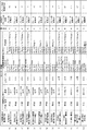
図5は、本発明の第2の実施の形態に係る人力駆動車のブレーキ制御装置の人力駆動車の駆動状態を判定するためのテーブル6の一例を示す図である。このテーブル6は、加速度角速度センサー4及び速度センサー5の検出する各センサー情報の組と、現在のブレーキの状態とに対応させて人力駆動車の駆動状態及びブレーキの制御方針を指定する。テーブル6内の“人力駆動車の駆動状態”は、(a)から(h)の場合は人力駆動車の減速の状態を示している。(i)から(m)の場合は人力駆動車の暴走の状態を示している。前進/後退”は人力駆動車の前進/後退を示し速度センサー5の速度がプラスのとき前進、マイナスのとき後進とする。“速度”は速度センサー5の速度を示し、(a)から(h)の場合のVtは、適度な減速(例えば、0.5G(Gは重力の加速度)程度)が行われた場合の減速中におけるブレーキ作動開始からt時間経過したときの人力駆動車の速度を示す。“加速度”は加速度角速度センサー4の加速度を示し単位はG(重力の加速度)である。“角速度”は加速度角速度センサー4の角速度を示し単位はdeg/s(度/秒)である。“優先度”は、“人力駆動車の駆動状態”の緊急度、危険度の度合い(AからDの順)を示す。制御部3が“優先度”に基づいて “人力駆動車の駆動状態”を選択する。“現在のブレーキの状態”は現在のブレーキが作動中なのか解除中なのかを示す。“ブレーキの制御方針”は、“ブレーキ作動中”の場合は、ブレーキの制動力の変更方針を示す。例えば、ブレーキ作動時のブレーキの制動力を8レベルに分け、現在のレベルの制動力から上下させるレベル数を指定する。また、“ブレーキ解除中”の場合は、ブレーキを作動させ、かつブレーキに制動力を掛けるための方針(例えば、ブレーキの位置の移動数)を示す。例えばブレーキを掛ける場合、“ブレーキ解除中”のブレーキの位置を1、ブレーキが掛かる位置を8として、ブレーキの掛かる位置以上までのブレーキの位置の移動数を指定する。すなわち、+7の場合は、ブレーキの位置は8となる。8以上の位置でブレーキが掛かり、制動力が強くなる。すなわち、“人力駆動車の駆動状態”が(i)から(m)の場合(人力駆動車が暴走の状態)には、8以上の位置でブレーキを掛けて暴走を止める。D.C.(Don’t care)は何でも良いことを示す。
FIG. 5 is a diagram showing an example of the table 6 for determining the driving state of the human-powered vehicle in the brake control device for the human-powered vehicle according to the second embodiment of the present invention. This table 6 designates the driving state of the manpowered vehicle and the brake control policy in correspondence with the set of sensor information detected by the acceleration
したがって、例えば(g)は、人力駆動車が前進、速度センサー5の示す速度がVtの20%以下、加速度がGx<−1G、角速度が90deg/s<Ay、そして、ブレーキ作動中の場合、“人力駆動車の駆動状態”は“前進中の減速が急激“であると判定し、ブレーキの制動力を4レベル下げることを示す”ブレーキの制御方針“を選択する。(g)以外の(a)から(m)も(g)と同様に、各センサー情報の組と、現在のブレーキの状態とに対応させて、人力駆動車の駆動状態を判定しブレーキの制御方針を示している。
Thus, for example, (g) is when the manpowered vehicle moves forward, the speed indicated by the
尚、図5で示すテーブル6内の各データ各情報等は、これにこだわることなく最適なものを実験等により適宜決めて良い。 It should be noted that each data item in the table 6 shown in FIG.
図6は、ブレーキ作動中における人力駆動車のブレーキの制動力を制御したときの人力駆動車の減速の変化を示す図である。 FIG. 6 is a diagram showing a change in deceleration of the manpowered vehicle when the braking force of the brake of the manpowered vehicle is controlled during the brake operation.
ここで、人力駆動車のブレーキ制御装置1の動作を説明する。制御部3は、人力駆動車のブレーキの作動中に、図4で示す加速度角速度センサー4の検出した加速度及び角速度と、人力駆動車の例えば座席の下に設けられた速度センサー5の検出した人力駆動車の速度とを取り込む。そして、これら加速度、角速度、人力駆動車の速度とから、図5で示すテーブル6を使用し、人力駆動車の駆動状態を判定する。制御部3はこの判定を例えば10msecから20msecの間隔で実施する。制御部3はこの判定した人力駆動車の駆動状態に対応したブレーキの制御方針に基づいて、人力駆動車が安全に走行できるようにブレーキの制動力を制御する。ブレーキの制動力の制御について、図6を使用して説明する。図6は走行中の人力駆動車のブレーキが作動して人力駆動車が停止するまでの速度と時間のイメージを示す。図6の(a)は、適度な減速(例えば、0.5G程度)が行われた状態を示しており、図中のVtは減速中におけるブレーキ作動開始からある時間tが経過したときの速度を示す。図6の(b)で示すように、現在の速度が、例えばVtの20%以下の場合は、図5のテーブル6により、減速がやや強いあるいは減速が急激であると判断して、ブレーキの制動力を下げ、減速の度合いを緩やかにする。また、逆に、図6の(c)のように、現在の速度が、例えばVtの20%以上の場合は、図5のテーブル6により、減速が不十分であると判断して、ブレーキの制動力を強め、減速の度合いを強める。
Here, the operation of the
ここで、ブレーキの一例を図7を参照して説明する。図7は本発明の実施の形態に係る人力駆動車のブレーキ制御装置の制御するブレーキの一例を説明する図である。図7の(b)の右図に示すように、サーボモータ14が制御部3の指示に基づいて回転し、サーボモータ14に接続されたブレーキワイヤー15がサーボモータ14の回転状況(回転角度、回転方向)をブレーキに伝えブレーキを制御する。サーボモータ14は駆動パルス信号のパルス幅の長さに応じて回転状況が変化する。図7の(a)に示すように、ブレーキの制動力を強めたり弱めたりする調整はパルス幅を16段階(例えば1msecから2msecの間)に変化させることで実現する。最小パルス幅は1msec、最大パルス幅は2msecであり、中間のパルス幅は(1+(n−1)×t)msecである。ここで、nはパルス幅の段階数、tは段階間のパルス幅の差であり、t=(最大パルス幅2msec−最小パルス幅1msec)/15msec、すなわち、t=1/15msecである。駆動パルス信号の周期は例えば10msecから20msecの間である。図7の(b)では、段階数n=1のパルス幅、すなわち1msecのパルス幅の駆動パルス信号をサーボモータ14へ出力するとサーボモータ14は−60度まで回転し、ブレーキは解除状態となる。図7の(c)では、段階数n=8のパルス幅、すなわち(1+7/15)msec=約1.5msecのパルス幅の駆動パルス信号をサーボモータ14へ出力するとサーボモータ14は約+0度まで回転し、ブレーキは作動状態となる。さらに、図7の(d)では、段階数n=16のパルス幅、すなわち(1+15/15)msec=2msecのパルス幅の駆動パルス信号をサーボモータ14へ出力するとサーボモータ14は+60度まで回転し、ブレーキは最大制動力での作動状態となる。ここで、サーボモータ14の回転角度は−60度〜+60度であるが、採用するサーボモータの種類によって回転角度は異なる。
Here, an example of the brake will be described with reference to FIG. FIG. 7 is a view for explaining an example of a brake controlled by the brake control device for a manpowered vehicle according to the embodiment of the present invention. As shown in the right diagram of FIG. 7B, the servo motor 14 rotates based on an instruction from the
したがって、制御部3は、例えば図5で示すテーブル6内の“ブレーキの制御方針“で示す‘制動力の上下させるレベル数’、又は‘ブレーキの位置の移動数’に応じた回転状況になるようなパルス幅を決める。そして、このパルス幅の駆動パルス信号をサーボモータ14に出力する。
(第3の実施の形態)
図8は、本発明の第3の実施の形態に係る人力駆動車の一例を示す図である。図8では、人力駆動車を車椅子として示し、車椅子を用いて説明する。
Therefore, for example, the
(Third embodiment)
FIG. 8 is a diagram illustrating an example of a human-powered vehicle according to the third embodiment of the present invention. In FIG. 8, a human-powered vehicle is shown as a wheelchair, and it demonstrates using a wheelchair.
本実施の形態に係る人力駆動車、例えば車椅子9は、駆動輪10と、ブレーキ装置11と、ハンドリム12と、制御部13とにより構成する。駆動輪10は、回転することにより車椅子9を動かす。ハンドリム12は、駆動輪10の外側(軸方向の外側)に駆動輪10と数箇所で結合されて付加され、押すことにより駆動輪10を回転させる。ブレーキ装置11は、指示に基づき駆動輪10に制動を掛けたり駆動輪10の制動を解除したりする。制御部13は、例えば、ブレーキ装置11に対して駆動輪10に制動を掛ける指示を出してブレーキ装置11により駆動輪10に制動が掛った状態で車椅子9を坂道に停める。そして、制御部13は、車椅子9が坂道に停まっているときに、ハンドリム12の操作に基づいて駆動輪10が回転した際に、この回転を検知しブレーキ装置11に駆動輪10の制動を解除する指示を出す。ブレーキ装置11は、この指示に基づき駆動輪10の制動を解除する。ここで、制御部13は、駆動輪10に制動が掛った状態で車椅子9が登り坂に停まっているときには、ハンドリム12の操作に基づいて車椅子9が前進する方向に駆動輪10が回転した際に、この回転を検知しブレーキ装置11に駆動輪10の制動を解除する指示を出す。また、制御部13は、駆動輪10に制動が掛った状態で車椅子9が下り坂に停まっているときには、ハンドリム12の操作に基づいて車椅子9が後退する方向に駆動輪10が回転した際に、この回転を検知しブレーキ装置11に駆動輪10の制動を解除する指示を出す。
A human-powered vehicle according to the present embodiment, for example, a wheelchair 9, includes a
すなわち、制御部13は、ブレーキ装置11に駆動輪10に制動を掛ける指示を出すと、ブレーキ装置11はこの指示に基づき駆動輪10に制動を掛ける。そして、車椅子9が駆動輪10に制動が掛って例えば坂道に斜めに停まっているときに、車椅子9の使用者が車椅子9を坂道発進する場合、車椅子9の使用者はハンドリム12を押して駆動輪10を回転させる。このとき、制御部13は、この回転を検知しブレーキ装置11に駆動輪10の制動を解除する指示を出す。ブレーキ装置11は、この指示に基づき駆動輪10の制動を解除する。
That is, when the
このように、本発明の第3の実施の形態によれば、車椅子が坂道に停まっているときに、車椅子の使用者がハンドリムを押して駆動輪を回転させ坂道発進する際、制御部がこの回転を検知しブレーキ装置に駆動輪の制動を解除する指示を出す。そして、ブレーキ装置がこの指示に基づき駆動輪の制動を解除する。このため、車椅子の使用者が車椅子を坂道発進する際に車椅子のブレーキが解除されるので、坂道発進するためにハンドリムを押してもハンドリムが重くなく、容易に坂道発進することができる。 Thus, according to the third embodiment of the present invention, when the wheelchair is stopped on a slope, when the user of the wheelchair pushes the hand rim to rotate the drive wheel and starts the slope, the control unit The rotation is detected and an instruction to release the braking of the driving wheel is issued to the brake device. Then, the brake device releases the braking of the driving wheel based on this instruction. For this reason, since the wheelchair user releases the wheelchair brake when the wheelchair user starts the hill, even if the hand rim is pushed to start the hill, the hand rim is not heavy and the hill can be started easily.
次に、本発明の実施の形態に係る人力駆動車の動作を図9から図19を参照して詳細に説明する。ここでは、人力駆動車を車椅子として示し、車椅子を用いて説明する。 Next, the operation of the human-powered vehicle according to the embodiment of the present invention will be described in detail with reference to FIGS. Here, a human-powered vehicle is shown as a wheelchair, and it demonstrates using a wheelchair.
図9は、図8に示す車椅子9においてブレーキ装置11の概要を付加した図である。この図において、ブレーキ装置11はサーボモータ14と、ブレーキワイヤー15と、リムブレーキ16と、スライド機構21とで構成する。サーボモータ14は、制御部13の指示に基づいて回転する。ブレーキワイヤー15は、サーボモータ14の回転状況(回転角度、回転方向)をリムブレーキ16に伝える。リムブレーキ16は、ブレーキパッド17を有し、ブレーキワイヤー15により伝えられたサーボモータ14の回転状況に基づいて駆動輪10にブレーキパッド17を押し当てたり駆動輪10から離したりする。スライド機構21は、ブレーキパッド17を駆動輪10に押し当てたときに駆動輪10の回転方向にリムブレーキ16を移動させる。
FIG. 9 is a diagram in which an outline of the brake device 11 is added to the wheelchair 9 shown in FIG. In this figure, the brake device 11 includes a servo motor 14, a brake wire 15, a rim brake 16, and a
図10は、本発明の第3の実施の形態に係る人力駆動車のブレーキ装置の一例を示す図である。ここでは、人力駆動車を車椅子として示し、車椅子を用いて説明する。ブレーキ装置11は、サーボモータ14と、回転状況伝達器19と、ブレーキワイヤー15と、リムブレーキ16と、スライド機構21とで構成する。回転状況伝達器19は、サーボモータ14の回転状況をブレーキワイヤー15に伝達する。ブレーキワイヤー15は回転状況伝達器19から伝達された回転状況をリムブレーキ16に伝達する。リムブレーキ16は、ブレーキワイヤー15により伝えられたサーボモータ14の回転状況に基づいて駆動輪10のリムにアーム18の先端に付いたブレーキパッド17を押し当てたり駆動輪10のリムから離したりすることにより駆動輪10に制動を掛けたり駆動輪10の制動を解除したりする。
FIG. 10 is a diagram illustrating an example of a brake device for a manpowered vehicle according to the third embodiment of the present invention. Here, a human-powered vehicle is shown as a wheelchair, and it demonstrates using a wheelchair. The brake device 11 includes a servo motor 14, a
図11は、本発明の第3の実施の形態に係る人力駆動車のリムブレーキがスライド機構上に取り付けられている様子の一例を示す図である。ここでは、人力駆動車を車椅子として示し、車椅子を用いて説明する。制御部13がブレーキ装置11に対して駆動輪10に制動を掛ける指示を出し車椅子9を坂道に停める際に、ブレーキパッド17が駆動輪10に押し当てられて駆動輪10が制動する。このとき、スライド機構21は、駆動輪10の回転方向の予め定めた位置(スライド機構21の端)にリムブレーキ16を移動させる。そして、スライド機構21は、駆動輪10に制動が掛った状態で車椅子9が坂道に停まっているときに、ハンドリム12の操作に基づいて駆動輪10が回転した際に、リムブレーキ16をスライド機構21の端から外れるようにする。そして、スライド機構21は、リムブレーキ16がスライド機構21の端から外れたことを示す信号を出力する。制御部13は、この信号を検知しブレーキ装置11に駆動輪10の制動を解除する指示を出す。ブレーキ装置11はこの指示に基づき駆動輪10の制動を解除する。
FIG. 11 is a diagram illustrating an example of a state in which a rim brake of a manpowered vehicle according to the third embodiment of the present invention is mounted on a slide mechanism. Here, a human-powered vehicle is shown as a wheelchair, and it demonstrates using a wheelchair. When the
ここで、坂道発進について説明する。 Here, the slope start will be described.
図11に示すように、リムブレーキ16は、車椅子9の車体に固定されたスライド機構21上に取り付けられている。リムブレーキ16は、スライド機構21上を例えば3から5cmほどスライドできる仕組みを持ち、スライド機構21の両端に接触センサー20を有する。リムブレーキ16とスライド機構21を繋ぐ可動部は摩擦抵抗が小さい機構を採用し、リムブレーキ16をスムーズにスライドできるようにする。
As shown in FIG. 11, the rim brake 16 is mounted on a
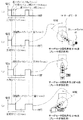
車椅子9が登り坂で停止し、坂道発進するときの動作を図12から図15を使用して説明する。図12から図15は、本発明の第3の実施の形態に係る人力駆動車の登り坂での坂道発進するときの動作を説明する図である。ここでは、人力駆動車を車椅子として示し、車椅子を用いて説明する。 The operation when the wheelchair 9 stops on the uphill and starts off the slope will be described with reference to FIGS. FIG. 12 to FIG. 15 are diagrams for explaining the operation when the hill drive starts on the uphill of the human-powered vehicle according to the third embodiment of the present invention. Here, a human-powered vehicle is shown as a wheelchair, and it demonstrates using a wheelchair.
図12に示すように車椅子9が登り坂にある場合、図13に示すようにブレーキ作動中ではリムブレーキ16が駆動輪10と同じ回転方向にスライドする。リムブレーキ16がスライド機構21の端に達したとき、接触センサー20がリムブレーキ16の接触を検出し接触センサー20の検出状態がOFFからONに変化する。制御部13がこの接触センサー20の検出状態を示す信号を検知する。その後、図14に示すように、ブレーキ作動中に登り坂を坂道発進しようと使用者がハンドリムを前方に押す(漕ぎ出す)とき、図15に示すように、リムブレーキ16がスライドしてスライド機構21の端から離れ、接触センサー20のリムブレーキ16の検出状態がONからOFFに変化する。制御部13がこの接触センサー20の検出状態を示す信号を検知する。制御部13は接触センサー20からの信号がONからOFFになったことを検知すると、ブレーキ装置11に駆動輪10の制動を解除する指示を出す。そして、ブレーキ装置11がこの指示に基づき駆動輪10の制動を解除する。このため、車椅子9の使用者が車椅子9を坂道発進する際に、車椅子9にブレーキ装置11による制動が掛かっていないので、坂道発進するためにハンドリム12を押してもハンドリム12が重くなく、容易に坂道発進することができる。
When the wheelchair 9 is on an uphill as shown in FIG. 12, the rim brake 16 slides in the same rotational direction as that of the
次に車椅子9が下り坂で停止し、坂道発進するときの動作を図16から図19を使用して説明する。図16から図19は、本発明の第3の実施の形態に係る人力駆動車の下り坂での坂道発進するときの動作を説明する図である。ここでは、人力駆動車を車椅子として示し、車椅子を用いて説明する。図16に示すように車椅子9が下り坂にある場合、図17に示すようにブレーキ作動中ではリムブレーキ16が登り坂のときとは反対の方向にスライドする。リムブレーキ16がスライド機構21の端に達したとき、接触センサー20がリムブレーキ16の接触を検出し接触センサー20の検出状態がOFFからONに変化する。制御部13がこの接触センサー20の検出状態を示す信号を検知する。その後、図18に示すように、ブレーキ作動中に下り坂を坂道発進しようと使用者がハンドリムを漕ぎ出すときは、図19に示すように一度、ハンドリム12を後進方向に例えば数cm動かし、リムブレーキ16をスライドさせてスライド機構21の端から離れさせる。すると、接触センサー20のリムブレーキ16の検出状態がONからOFFに変化する。制御部13がこの接触センサー20の検出状態を示す信号を検知する。制御部13は接触センサー20からの信号がONからOFFになったことを検知すると、ブレーキ装置11に駆動輪10の制動を解除する指示を出す。そして、ブレーキ装置11がこの指示に基づき駆動輪10の制動を解除する。このため、車椅子9の使用者が車椅子9を坂道発進する際に、車椅子9にブレーキ装置11による制動が掛かっていないので、坂道発進するためにハンドリム12を押してもハンドリム12が重くなく、容易に坂道発進することができる。
Next, the operation when the wheelchair 9 stops on the downhill and starts on the slope will be described with reference to FIGS. FIG. 16 to FIG. 19 are diagrams for explaining the operation when starting a downhill on the downhill of the human-powered vehicle according to the third embodiment of the present invention. Here, a human-powered vehicle is shown as a wheelchair, and it demonstrates using a wheelchair. When the wheelchair 9 is on the downhill as shown in FIG. 16, the rim brake 16 slides in the opposite direction to that on the uphill during the braking operation as shown in FIG. When the rim brake 16 reaches the end of the
このように、本発明の第3の実施の形態によれば、車椅子が坂道に停まっているときに、車椅子の使用者がハンドリムを押して駆動輪を回転させ坂道発進する際、制御部がこの回転を検知しブレーキ装置に駆動輪の制動を解除する指示を出す。そして、ブレーキ装置がこの指示に基づき駆動輪の制動を解除する。このため、車椅子の使用者が車椅子を坂道発進する際に、車椅子にブレーキ装置による制動が掛かっていないので、坂道発進するためにハンドリムを押してもハンドリムが重くなく、容易に坂道発進することができる。また、本発明の第3の実施の形態によれば、サーボモータによりブレーキワイヤーを介してリムブレーキを操作する構成を採用している。したがって、油圧ブレーキを使用していないので油圧ブレーキに必要なオイルを使用していない。このため、油圧ブレーキを車椅子に採用する場合に行っている、車椅子へブレーキを搭載する時の作業や車椅子の継続使用時での作業を行う必要がなくなり、車椅子へのブレーキの搭載や車椅子の維持が煩わしくなく容易である。 Thus, according to the third embodiment of the present invention, when the wheelchair is stopped on a slope, when the user of the wheelchair pushes the hand rim to rotate the drive wheel and starts the slope, the control unit The rotation is detected and an instruction to release the braking of the driving wheel is issued to the brake device. Then, the brake device releases the braking of the driving wheel based on this instruction. For this reason, when the user of the wheelchair starts the slope on the slope, the brake is not applied to the wheelchair, so even if the hand rim is pushed to start the slope, the hand rim is not heavy and the slope can be started easily. . In addition, according to the third embodiment of the present invention, a configuration is adopted in which a rim brake is operated via a brake wire by a servo motor. Therefore, since the hydraulic brake is not used, the oil necessary for the hydraulic brake is not used. For this reason, there is no need to perform work when installing a brake on a wheelchair or when using a wheelchair, and maintaining a wheelchair, and maintaining the wheelchair. Is not bothersome and easy.
尚、上記した人力駆動車のブレーキ装置は、本発明の第1の実施の形態及び第2の実施の形態に掛かる人力駆動車のブレーキ制御装置により制御されるようにしても良い。 The above-described brake device for a manpowered vehicle may be controlled by the brake control device for a manpowered vehicle according to the first and second embodiments of the present invention.
また、本発明について上記のように人力駆動車を車椅子を用いて説明したが、ベビーカー、三輪車、自転車等、車椅子と同様に人力で駆動する車であれば良く、車椅子に限定されない。 Moreover, although the human-powered vehicle was demonstrated using the wheelchair as mentioned above about this invention, it should just be a vehicle driven by human power similarly to a wheelchair, such as a stroller, a tricycle, and a bicycle, and is not limited to a wheelchair.
1 人力駆動車のブレーキ制御装置
2 センサー
3 制御部
4 加速度角速度センサー
5 速度センサー
6 テーブル
9 車椅子
10 駆動輪
11 ブレーキ装置
12 ハンドリム
13 制御部
14 サーボモータ
15 ブレーキワイヤー
16 リムブレーキ
17 ブレーキパッド
18 アーム
19 回転状況伝達器
20 接触センサー
21 スライド機構
DESCRIPTION OF
Claims (9)
前記センサーが検出した前記人力駆動車の移動状況から前記人力駆動車の駆動状態を判定し、前記人力駆動車のブレーキの作動中に、前記判定した前記人力駆動車の駆動状態に基づいて、前記人力駆動車の減速の度合いを弱めるように前記人力駆動車のブレーキの制動力を制御する制御部と、
を備え、
前記人力駆動車の移動状況を検出する前記センサーは、
前記人力駆動車に設定した座標軸の各方向の加速度と、前記座標軸周りの各角速度とを検出する加速度角速度センサーと、
前記人力駆動車の速度を検出する速度センサーと、を含み、
前記制御部は、前記加速度角速度センサーの検出した前記加速度及び前記角速度と前記速度センサーの検出した前記人力駆動車の速度とから前記人力駆動車の駆動状態を判定し、この判定した人力駆動車の駆動状態に基づいて前記ブレーキの制動力を制御する、
ことを特徴とする人力駆動車のブレーキ制御装置。 A sensor that detects the movement of a manpowered vehicle;
The driving state of the human-powered vehicle is determined from the movement state of the human-powered vehicle detected by the sensor, and during the operation of the brake of the human-powered vehicle, based on the determined driving state of the human-powered vehicle, A control unit for controlling the braking force of the brake of the manpowered vehicle so as to weaken the degree of deceleration of the manpowered vehicle;
With
The sensor for detecting the movement status of the human-powered vehicle is:
An acceleration angular velocity sensor that detects acceleration in each direction of the coordinate axis set in the human-powered vehicle and each angular velocity around the coordinate axis;
A speed sensor for detecting the speed of the human-powered vehicle,
The control unit determines the driving state of the human-powered vehicle from the acceleration and angular velocity detected by the acceleration angular velocity sensor and the speed of the human-powered vehicle detected by the speed sensor, and the determined human-powered vehicle Controlling the braking force of the brake based on the driving state;
A brake control device for a human-powered vehicle.
前記制御部は、前記テーブルを使用して前記人力駆動車の駆動状態を調べ、この状態に対応する前記ブレーキの制御方針に基づいて前記ブレーキの制動力を制御する、
ことを特徴とする請求項1又は2記載の人力駆動車のブレーキ制御装置。 A table for designating the driving state of the human-powered vehicle and the control policy of the brake in correspondence with a set of sensor information detected by the acceleration angular velocity sensor and the speed sensor and a current brake state;
The control unit examines the driving state of the manpowered vehicle using the table, and controls the braking force of the brake based on the braking control policy corresponding to this state.
The brake control device for a manpowered vehicle according to claim 1 or 2 .
指示に基づき前記駆動輪に制動を掛けたり前記駆動輪の制動を解除したりするブレーキ装置と、
前記駆動輪に付加され、押すことにより前記駆動輪を回転させるハンドリムと、
前記ブレーキ装置に前記駆動輪に制動を掛ける指示を出し前記ブレーキ装置により前記駆動輪に制動が掛った状態で、自人力駆動車が坂道に停まっているときに、前記ハンドリムの操作に基づいて前記駆動輪が回転した際に、この回転を検知し前記ブレーキ装置に前記駆動輪の制動を解除する指示を出す制御部と、
を備え、
前記制御部は、前記駆動輪に制動が掛った状態で自人力駆動車が下り坂に停まっているときに、前記ハンドリムの操作に基づいて自人力駆動車が後進する方向に前記駆動輪が回転した際に、この回転を検知し前記ブレーキ装置に前記駆動輪の制動を解除する指示を出す、
ことを特徴とする人力駆動車。 A drive wheel that moves a self-powered vehicle by rotating;
A brake device for braking the driving wheel or releasing the braking of the driving wheel based on an instruction;
A hand rim that is added to the drive wheel and rotates the drive wheel by pushing;
Based on the operation of the hand rim, when an instruction to brake the driving wheel is given to the braking device and the driving wheel is stopped on a slope with the braking device being braked by the braking device When the drive wheel rotates, a control unit that detects this rotation and issues an instruction to release the braking of the drive wheel to the brake device;
With
The control unit is configured such that when the self-powered drive vehicle is stopped on a downhill with the drive wheel being braked, the drive wheel is moved in a direction in which the self-powered drive vehicle moves backward based on the operation of the hand rim. When rotating, this rotation is detected and an instruction to release the braking of the drive wheel is issued to the brake device.
This is a human-powered vehicle.
指示に基づき前記駆動輪に制動を掛けたり前記駆動輪の制動を解除したりするブレーキ装置と、
前記駆動輪に付加され、押すことにより前記駆動輪を回転させるハンドリムと、
前記ブレーキ装置に前記駆動輪に制動を掛ける指示を出し前記ブレーキ装置により前記駆動輪に制動が掛った状態で、自人力駆動車が坂道に停まっているときに、前記ハンドリムの操作に基づいて前記駆動輪が回転した際に、この回転を検知し前記ブレーキ装置に前記駆動輪の制動を解除する指示を出す制御部と、を備え、
前記制御部は、前記駆動輪に制動が掛った状態で自人力駆動車が登り坂に停まっているときに、前記ハンドリムの操作に基づいて自人力駆動車が前進する方向に前記駆動輪が回転した際に、この回転を検知し前記ブレーキ装置に前記駆動輪の制動を解除する指示を出し、
前記ブレーキ装置は、
ブレーキパッドを有し、前記制御部の出力した指示に基づいて前記ブレーキパッドを前記駆動輪に押し当てたり前記駆動輪から離したりすることにより前記駆動輪に制動を掛けたり前記駆動輪の制動を解除したりするリムブレーキと、
前記制御部が前記ブレーキ装置に前記駆動輪に制動を掛ける指示を出し自人力駆動車を坂道に停める際に、前記ブレーキパッドが前記駆動輪に押し当てられて前記駆動輪が制動するときに前記駆動輪の回転方向の予め定めた位置に前記リムブレーキを移動させ、前記駆動輪に制動が掛った状態で自人力駆動車が坂道に停まっているときに、前記ハンドリムの操作に基づいて前記駆動輪が回転した際に、前記リムブレーキを前記予め定めた位置から外れるようにし、この位置から外れたことを示す信号を出力するスライド機構と、を有し、
前記制御部は、前記予め定めた位置から外れたことを示す前記信号を検知し前記ブレーキ装置に前記駆動輪の制動を解除する指示を出す、ことを特徴とする人力駆動車。 A drive wheel that moves a self-powered vehicle by rotating;
A brake device for braking the driving wheel or releasing the braking of the driving wheel based on an instruction;
A hand rim that is added to the drive wheel and rotates the drive wheel by pushing;
Based on the operation of the hand rim, when an instruction to brake the driving wheel is given to the braking device and the driving wheel is stopped on a slope with the braking device being braked by the braking device A control unit that detects the rotation when the driving wheel rotates and issues an instruction to release the braking of the driving wheel to the brake device;
The control unit is configured to move the driving wheel in a direction in which the driving vehicle moves forward based on the operation of the hand rim when the driving vehicle is stopped on an uphill while the driving wheel is braked. When rotating, this rotation is detected and an instruction to release the braking of the driving wheel is issued to the brake device,
The brake device is
A brake pad is provided, and the drive wheel is braked or the drive wheel is braked by pressing the brake pad against the drive wheel or separating it from the drive wheel based on an instruction output from the control unit. Rim brakes to release,
When the control unit instructs the brake device to brake the driving wheel and stops the self-powered vehicle on a slope, the brake pad is pressed against the driving wheel and the driving wheel brakes. The rim brake is moved to a predetermined position in the rotation direction of the drive wheel, and when the self-powered drive vehicle is stopped on a slope with the drive wheel being braked, the rim brake is operated based on the operation of the hand rim. A slide mechanism for causing the rim brake to come off from the predetermined position when the drive wheel rotates, and outputting a signal indicating that it has come off from this position;
The human-powered vehicle, wherein the control unit detects the signal indicating that the control unit has deviated from the predetermined position and issues an instruction to release the braking of the driving wheel to the brake device.
ブレーキパッドを有し、前記制御部の出力した指示に基づいて前記ブレーキパッドを前記駆動輪に押し当てたり前記駆動輪から離したりすることにより前記駆動輪に制動を掛けたり前記駆動輪の制動を解除したりするリムブレーキと、
前記制御部が前記ブレーキ装置に前記駆動輪に制動を掛ける指示を出し自人力駆動車を坂道に停める際に、前記ブレーキパッドが前記駆動輪に押し当てられて前記駆動輪が制動するときに前記駆動輪の回転方向の予め定めた位置に前記リムブレーキを移動させ、前記駆動輪に制動が掛った状態で自人力駆動車が坂道に停まっているときに、前記ハンドリムの操作に基づいて前記駆動輪が回転した際に、前記リムブレーキを前記予め定めた位置から外れるようにし、この位置から外れたことを示す信号を出力するスライド機構と、を有し、
前記制御部は、前記予め定めた位置から外れたことを示す前記信号を検知し前記ブレーキ装置に前記駆動輪の制動を解除する指示を出す、ことを特徴とする請求項5に記載された人力駆動車。 The brake device is
A brake pad is provided, and the drive wheel is braked or the drive wheel is braked by pressing the brake pad against the drive wheel or separating it from the drive wheel based on an instruction output from the control unit. Rim brakes to release,
When the control unit instructs the brake device to brake the driving wheel and stops the self-powered vehicle on a slope, the brake pad is pressed against the driving wheel and the driving wheel brakes. The rim brake is moved to a predetermined position in the rotation direction of the drive wheel, and when the self-powered drive vehicle is stopped on a slope with the drive wheel being braked, the rim brake is operated based on the operation of the hand rim. A slide mechanism for causing the rim brake to come off from the predetermined position when the drive wheel rotates, and outputting a signal indicating that it has come off from this position;
6. The human power according to claim 5, wherein the control unit detects the signal indicating that the position has deviated from the predetermined position, and instructs the brake device to release braking of the driving wheel. Driving car.
前記制御部の指示に基づいて回転するサーボモータと、
前記サーボモータの回転状況を前記リムブレーキに伝えるブレーキワイヤーと、
前記ブレーキワイヤーにより伝えられた前記サーボモータの回転状況に基づいて前記駆動輪に前記ブレーキパッドを押し当てたり前記駆動輪から離したりする前記リムブレーキと、
前記ブレーキパッドを前記駆動輪に押し当てたときに前記駆動輪の回転方向に前記リムブレーキを移動させる前記スライド機構と、
を備えたことを特徴とする請求項7又は8記載の人力駆動車。 The brake device is
A servo motor that rotates based on an instruction from the control unit;
A brake wire for transmitting the rotation status of the servo motor to the rim brake;
The rim brake that presses the brake pad against the driving wheel or releases it from the driving wheel based on the rotation state of the servo motor transmitted by the brake wire;
The slide mechanism for moving the rim brake in the rotational direction of the drive wheel when the brake pad is pressed against the drive wheel;
The human-powered vehicle according to claim 7 or 8, further comprising:
Priority Applications (1)
| Application Number | Priority Date | Filing Date | Title |
|---|---|---|---|
| JP2012034293A JP5932385B2 (en) | 2012-02-20 | 2012-02-20 | Brake control device for man-powered vehicle and man-powered vehicle |
Applications Claiming Priority (1)
| Application Number | Priority Date | Filing Date | Title |
|---|---|---|---|
| JP2012034293A JP5932385B2 (en) | 2012-02-20 | 2012-02-20 | Brake control device for man-powered vehicle and man-powered vehicle |
Publications (2)
| Publication Number | Publication Date |
|---|---|
| JP2013169871A JP2013169871A (en) | 2013-09-02 |
| JP5932385B2 true JP5932385B2 (en) | 2016-06-08 |
Family
ID=49264104
Family Applications (1)
| Application Number | Title | Priority Date | Filing Date |
|---|---|---|---|
| JP2012034293A Active JP5932385B2 (en) | 2012-02-20 | 2012-02-20 | Brake control device for man-powered vehicle and man-powered vehicle |
Country Status (1)
| Country | Link |
|---|---|
| JP (1) | JP5932385B2 (en) |
Families Citing this family (3)
| Publication number | Priority date | Publication date | Assignee | Title |
|---|---|---|---|---|
| JP5442899B1 (en) * | 2013-08-11 | 2014-03-12 | 俊之介 島野 | Safety system for baby carriage or nursing vehicle |
| JP5922200B2 (en) * | 2014-08-27 | 2016-05-24 | シャープ株式会社 | Walking assistance device, method for controlling walking assistance device, and program for causing computer to control walking assistance device |
| KR101743262B1 (en) | 2015-12-24 | 2017-06-07 | 주식회사 효원파워텍 | Device and method for controlling assist power |
Family Cites Families (3)
| Publication number | Priority date | Publication date | Assignee | Title |
|---|---|---|---|---|
| JP2001029396A (en) * | 1999-07-19 | 2001-02-06 | Hetsuzu:Kk | Controller for wheelchair wheel |
| JP2003320935A (en) * | 2002-04-30 | 2003-11-11 | Sanyo Electric Co Ltd | Electric-motor vehicle |
| JP2007075479A (en) * | 2005-09-16 | 2007-03-29 | Toshihiko Yasuda | One-handed wheelchair with traveling assist function |
-
2012
- 2012-02-20 JP JP2012034293A patent/JP5932385B2/en active Active
Also Published As
| Publication number | Publication date |
|---|---|
| JP2013169871A (en) | 2013-09-02 |
Similar Documents
| Publication | Publication Date | Title |
|---|---|---|
| CN111032478B (en) | Children's vehicle frame and children's vehicle | |
| JP6830882B2 (en) | Brake control and brake system | |
| US10800484B2 (en) | Scooter, control device and controlling method | |
| WO2008016074A1 (en) | Running device, and braking control method for the running device | |
| JP2018061819A (en) | Electric vehicle | |
| JP2009183407A (en) | Walking aid device | |
| JP5932385B2 (en) | Brake control device for man-powered vehicle and man-powered vehicle | |
| JPWO2014174554A1 (en) | Mobile radiography system | |
| JP2014176256A (en) | Regeneration control device | |
| JP6059279B2 (en) | Program for controlling walking assistance vehicles and walking assistance vehicles | |
| JP2016182268A (en) | Walking assisting device, method for controlling walking assisting device, and program to cause computer to control walking assisting device | |
| CN109982761B (en) | Vehicle comprising an electric motor and method of starting an electric motor for propelling a vehicle | |
| WO2014166336A1 (en) | Anti-lock brake system for electric riding vehicle and anti-lock device thereof | |
| TWI474814B (en) | Wheelchair constant speed safety device | |
| JP2005297749A (en) | Brake control system for battery type riding golf cart | |
| JP2017036009A (en) | Bicycle speed control device and bicycle | |
| JP6072975B2 (en) | Bogie equipment | |
| JP2022073187A (en) | Control device for human power-driven vehicle | |
| WO2016121465A1 (en) | Walking assisting vehicle | |
| JP2006054982A (en) | Electric motor type cart | |
| CN114466637A (en) | Electric vehicle, method for controlling electric vehicle, and program for controlling electric vehicle | |
| JP2021065468A (en) | Electric vehicle, and control method and control program of electric vehicle | |
| WO2017215601A1 (en) | Power control method and apparatus, vehicle and computer storage medium | |
| CN204527458U (en) | A kind of device with pedal with the self-balancing wheelbarrow of center of gravity self-regulating function | |
| JP5922200B2 (en) | Walking assistance device, method for controlling walking assistance device, and program for causing computer to control walking assistance device |
Legal Events
| Date | Code | Title | Description |
|---|---|---|---|
| A621 | Written request for application examination |
Free format text: JAPANESE INTERMEDIATE CODE: A621 Effective date: 20150119 |
|
| A977 | Report on retrieval |
Free format text: JAPANESE INTERMEDIATE CODE: A971007 Effective date: 20151221 |
|
| A131 | Notification of reasons for refusal |
Free format text: JAPANESE INTERMEDIATE CODE: A131 Effective date: 20160105 |
|
| A521 | Written amendment |
Free format text: JAPANESE INTERMEDIATE CODE: A523 Effective date: 20160302 |
|
| TRDD | Decision of grant or rejection written | ||
| A01 | Written decision to grant a patent or to grant a registration (utility model) |
Free format text: JAPANESE INTERMEDIATE CODE: A01 Effective date: 20160405 |
|
| A61 | First payment of annual fees (during grant procedure) |
Free format text: JAPANESE INTERMEDIATE CODE: A61 Effective date: 20160428 |
|
| R150 | Certificate of patent or registration of utility model |
Ref document number: 5932385 Country of ref document: JP Free format text: JAPANESE INTERMEDIATE CODE: R150 |