JP2005297749A - Brake control system for battery-powered golf carts - Google Patents
Brake control system for battery-powered golf carts Download PDFInfo
- Publication number
- JP2005297749A JP2005297749A JP2004116420A JP2004116420A JP2005297749A JP 2005297749 A JP2005297749 A JP 2005297749A JP 2004116420 A JP2004116420 A JP 2004116420A JP 2004116420 A JP2004116420 A JP 2004116420A JP 2005297749 A JP2005297749 A JP 2005297749A
- Authority
- JP
- Japan
- Prior art keywords
- brake
- battery
- golf cart
- control unit
- detection switch
- Prior art date
- Legal status (The legal status is an assumption and is not a legal conclusion. Google has not performed a legal analysis and makes no representation as to the accuracy of the status listed.)
- Abandoned
Links
Images


Landscapes
- Electric Propulsion And Braking For Vehicles (AREA)
- Valves And Accessory Devices For Braking Systems (AREA)
- Regulating Braking Force (AREA)
Abstract
【課題】 ドラムブレーキ12a〜dの系統が故障をした場合でも、バッテリー式乗用ゴルフカートを安全に停止をさせることができるブレーキ制御システムを提供する。
【解決手段】 バッテリー式乗用ゴルフカートのブレーキ制御システムとして、ドラムブレーキ12a〜d、駆動モータ9による回生制動及び電磁クラッチブレーキ11を併用して車両の制動をかける。ここで、ブレーキ検出スイッチ35と失陥検出スイッチ37の双方からの信号が走行制御部7に入力された場合には、走行制御部7はドラムブレーキ12a〜dが故障をしたと判断する。そして、走行制御部7は、駆動モータ9による回生制動によって規定速度まで減速をさせた後に、電磁クラッチブレーキ11を作動させて緊急停止をする。なお、走行制御部7は、緊急停止をすることを乗員に連絡するとともに、減速時の加速度が0.3Gを超えないように駆動モータ9による回生制動力を制御する。
【選択図】 図1PROBLEM TO BE SOLVED: To provide a brake control system capable of safely stopping a battery-powered riding golf cart even when a system of drum brakes 12a to d fails.
As a brake control system for a battery-powered riding golf cart, braking of a vehicle is performed by using drum brakes 12a to 12d, regenerative braking by a drive motor 9, and electromagnetic clutch brake 11 in combination. Here, when signals from both the brake detection switch 35 and the failure detection switch 37 are input to the travel control unit 7, the travel control unit 7 determines that the drum brakes 12a to 12d have failed. Then, the traveling control unit 7 decelerates to a specified speed by regenerative braking by the drive motor 9, and then operates the electromagnetic clutch brake 11 to make an emergency stop. The traveling control unit 7 notifies the occupant that an emergency stop will be performed, and controls the regenerative braking force by the drive motor 9 so that the acceleration during deceleration does not exceed 0.3 G.
[Selection] Figure 1
Description
本発明は、バッテリー式乗用ゴルフカートに関するものであり、詳細にはそのブレーキ制御システムに関するものである。 The present invention relates to a battery-powered golf cart, and more particularly to a brake control system thereof.
従来より、ゴルフ場内において、ゴルフプレーヤやゴルフバッグを自動運転又は手動運転により搬送する車両として、バッテリー式乗用ゴルフカートが用いられている。 Conventionally, battery-powered riding golf carts have been used as vehicles for carrying golf players and golf bags by automatic driving or manual driving in golf courses.
これらのバッテリー式乗用ゴルフカートには、乗り心地の向上、回生制動により得られる電力の利用、安全性の向上などから、ドラムブレーキ、駆動モータによる回生制動及び電磁クラッチブレーキの3系統の制動装置を併用して用いるブレーキ制御システムが開示されている(例えば、特許文献1参照。)。そして、これらの3系統のブレーキを併用することによって、乗り心地がよく、安全性の高いブレーキ制御システムを提供することができる。 These battery-powered golf carts are equipped with three types of braking devices: drum brakes, regenerative braking by drive motors and electromagnetic clutch brakes, in order to improve riding comfort, use electric power obtained by regenerative braking, and improve safety. A brake control system used in combination is disclosed (for example, see Patent Document 1). By using these three types of brakes in combination, it is possible to provide a brake control system that is comfortable to ride and has high safety.
ここで、実際の運転時においては、これら3系統のブレーキのうちで、ドラムブレーキの使用が最も細やかな制動制御をかけることができる。すなわち、自動運転をする場合においても手動運転をする場合においても、ドラムブレーキによって制動をかける手法が、車両の速度制御をしやすいということができる。 Here, during actual driving, among the three systems of brakes, it is possible to apply the most delicate braking control using the drum brake. That is, it can be said that the method of applying the brakes by the drum brake is easy to control the speed of the vehicle in both cases of automatic driving and manual driving.
しかしながら、ドラムブレーキの系統において、例えば、ブレーキシリンダの故障やブレーキオイル配管系統の破損によるオイル漏れなどの故障が生じることがある。このような場合には、回生制動による制動では制動力が不足することや、電磁クラッチブレーキによる制動ではスムーズに停止ができないという問題点がある。 However, in a drum brake system, for example, a failure such as a brake cylinder failure or an oil leak due to a breakage of a brake oil piping system may occur. In such a case, there is a problem that the braking force is insufficient in the braking by regenerative braking and that the braking by the electromagnetic clutch brake cannot be smoothly stopped.
本発明の目的は、ドラムブレーキの系統が故障をしたような場合でも、乗用ゴルフカートを安全に停止をさせることができる、いわゆるフェール・セーフ・システムを備えたバッテリー式乗用ゴルフカートのブレーキ制御システムに関するものである。 An object of the present invention is to provide a brake control system for a battery-powered riding golf cart equipped with a so-called fail-safe system that can safely stop the riding golf cart even when the drum brake system fails. It is about.
上記課題を解決するために、本発明のブレーキ制御システムでは、ブレーキペダルが踏み込まれていること、及び、通常のブレーキペダルの制動領域を越えて踏み込まれていることを検知して、乗用ゴルフカートを安全に停止させることができるようにしたものである。 In order to solve the above-mentioned problems, in the brake control system of the present invention, it is detected that the brake pedal is depressed and that the brake pedal is depressed beyond the braking area of the normal brake pedal, and the golf cart for riding is used. Can be safely stopped.
すなわち、請求項1の発明は、ドラムブレーキ、駆動モータによる回生制動及び電磁クラッチブレーキを併用して車両に制動をかけるバッテリー式乗用ゴルフカートのブレーキ制御システムにおいて、前記バッテリー式乗用ゴルフカートは、前記ドラムブレーキの作動を検知するブレーキ検出スイッチと、前記ドラムブレーキの失陥を検知する失陥検出スイッチとを備えており、前記ブレーキ検出スイッチと前記失陥検出スイッチの双方からの信号が走行制御部に入力された場合には、該走行制御部は、前記駆動モータによる回生制動をかけることによって規定速度まで前記バッテリー式乗用ゴルフカートを減速をさせた後に、前記電磁クラッチブレーキを作動させて緊急停止をすることを特徴としている。 That is, the invention of claim 1 is a brake control system for a battery-powered riding golf cart that brakes a vehicle using a drum brake, a regenerative braking by a drive motor, and an electromagnetic clutch brake. A brake detection switch for detecting the operation of the drum brake; and a failure detection switch for detecting the failure of the drum brake. A signal from both the brake detection switch and the failure detection switch The driving control unit decelerates the battery-powered riding golf cart to a specified speed by applying regenerative braking by the drive motor, and then operates the electromagnetic clutch brake to make an emergency stop. It is characterized by doing.
請求項2の発明は、請求項1の発明において、前記走行制御部は、前記駆動モータからの回生制動電流と前記バッテリー式乗用ゴルフカートの走行速度から、減速時の加速度が一定範囲を超えないように回生制動力を制御することを特徴としている。 According to a second aspect of the present invention, in the first aspect of the present invention, the traveling control unit is configured such that the acceleration during deceleration does not exceed a certain range from the regenerative braking current from the drive motor and the traveling speed of the battery-powered riding golf cart. Thus, the regenerative braking force is controlled as described above.
請求項3の発明は、請求項1又は請求項2の発明において、前記走行制御部は、前記ブレーキ検出スイッチと前記失陥検出スイッチの双方からの信号が入力された場合には、前記バッテリー式乗用ゴルフカートが、緊急停止をすることを乗員に連絡することを特徴としている。 According to a third aspect of the present invention, in the first or second aspect of the present invention, when the driving control unit receives signals from both the brake detection switch and the failure detection switch, the battery type A riding golf cart is characterized by notifying an occupant of an emergency stop.
本発明に係わるブレーキ制御システムを用いることによって、ドラムブレーキの系統が故障をしたような場合でも、バッテリー式乗用ゴルフカートを安全に、且つ、スムーズに停止をさせることができる。 By using the brake control system according to the present invention, it is possible to stop the battery-powered golf cart safely and smoothly even when the drum brake system fails.
以下に本発明の実施の形態を図面に基づいて説明する。 Embodiments of the present invention will be described below with reference to the drawings.
1.バッテリー式乗用ゴルフカートの構成
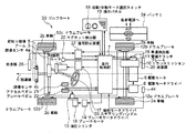
図3は、本発明の一実施例を示す電磁誘導式のバッテリー式乗用ゴルフカートの構成を示すブロック図である。なお、このバッテリー式乗用ゴルフカートは、乗員がステアリングハンドル23、アクセルペダル21及びブレーキペダル22を操作することによって、手動で運転をすることもできる。
1. Configuration of Battery Type Riding Golf Cart FIG. 3 is a block diagram showing a configuration of an electromagnetic induction type battery driving golf cart according to an embodiment of the present invention. The battery-powered riding golf cart can also be driven manually by operating the steering handle 23, the accelerator pedal 21 and the brake pedal 22 by the occupant.
また、図3に示すように、このゴルフカート30は、車体の前方中央に配置されている操舵モータ1の回転により舵取り機構5を操作し、前方の車輪2c、2dを自動で操舵することができる。そして、舵取り機構5の前方には、アーム3が装着されており、該アーム3は前方の車輪2c、2dとともに連動して左右に動くことができる。
Further, as shown in FIG. 3, the golf cart 30 can automatically steer the
アーム3の左右には、例えばコイルを用いた一対の誘導センサ4a、4bが備えられている。そして、走行路に敷設した誘導線6に低周波の交流電流を流すことにより誘導線6の上方に発生する磁界を、前記誘導線センサ4a、4bで検出し、検出した誘導信号により、走行制御部7、操舵モータドライバ17を介して操舵モータ1を駆動して車体を自動操舵させている。 On the left and right sides of the arm 3, for example, a pair of induction sensors 4a and 4b using coils are provided. The magnetic field generated above the guide wire 6 by passing a low-frequency alternating current through the guide wire 6 laid on the travel path is detected by the guide wire sensors 4a and 4b, and the travel control is performed based on the detected guide signal. The vehicle body is automatically steered by driving the steering motor 1 via the unit 7 and the steering motor driver 17.
自動走行中のゴルフカートの走行速度は、走行制御部7で制御される。すなわち、走行路のエリアに応じて走行制御部7に設定されている目標速度となるような速度指令が、走行制御部7から駆動モータドライバ8に出力され、駆動モータ9を回転させ、トランスミッション10を介して後の車輪2a、2bを回転させることによって車両が走行する。なお、車両の走行時には、駆動モータ9の回転軸に取り付けられた電磁クラッチブレーキ11に通電をすることによって、電磁クラッチブレーキ11を開放した状態にする。
The traveling speed of the golf cart during automatic traveling is controlled by the traveling control unit 7. That is, a speed command that is a target speed set in the travel control unit 7 according to the area of the travel path is output from the travel control unit 7 to the drive motor driver 8 to rotate the
ゴルフカート30が自動停止をする場合には、回生制動により駆動モータ9に制動をかけると同時に、車輪2a〜2dのおのおのに取り付けられた油圧式のドラムブレーキ12a〜12dを作動させて制動をかける。すなわち、走行制御部7は、制動指令をブレーキモータドライバ14に出力し、ブレーキモータ15の回転により油圧シリンダ13を加圧して、油圧式のドラムブレーキ12a〜12dを作動させて制動をかけるものである。
When the golf cart 30 automatically stops, the driving
その後、ゴルフカート30に制動がかかり、駆動モータ9の回転を検出する車速検出器16の検出速度がゼロになると、走行制御部7は電磁クラッチブレーキ11を閉じることによって、後の車輪2a、2bがロックされて、ゴルフカートは停止状態となる。
After that, when the golf cart 30 is braked and the detection speed of the vehicle speed detector 16 that detects the rotation of the
なお、ゴルフ場内の走行路上には、常時、複数台の電磁誘導式のゴルフカート30が自動で走行をしている。そこで、ゴルフカート30相互の追突を回避するために、車両の後部に送信機25、例えば、超音波式の発信機を備え、車両の前部に受信器26を備えている。そして、走行路の前を走行するゴルフカートの送信機25から発信される信号を、後続のゴルフカートの前方に設置した受信器26で受信する。そして、受信器26からの信号によって、後続のゴルフカート30を停止させるための追突防止装置27が備えられており、その停止指令で走行制御部7によって上述した停止制御が行われる。 Note that a plurality of electromagnetic induction golf carts 30 are always running automatically on the running road in the golf course. Therefore, in order to avoid a collision between the golf carts 30, a transmitter 25, for example, an ultrasonic transmitter is provided at the rear of the vehicle, and a receiver 26 is provided at the front of the vehicle. Then, the signal transmitted from the transmitter 25 of the golf cart traveling in front of the traveling path is received by the receiver 26 installed in front of the subsequent golf cart. Further, a rear-end collision prevention device 27 for stopping the subsequent golf cart 30 is provided by a signal from the receiver 26, and the stop control described above is performed by the traveling control unit 7 in accordance with the stop command.
なお、ゴルフコースではエリアごとにゴルフカート30を高速で運転をしたり、その逆に、低速で運転をしたい場合もある。そこで、走行路にあらかじめ埋め込まれている図示されていないマグネットの極性を検知することによって、ゴルフカート30に細かな速度制御ができるようになっている。すなわち、マグネット検出器20で、走行路6に埋め込まれているマグネットの極性を検知し、走行制御部7を介して走行速度の制御がされる方式である。 In some golf courses, the golf cart 30 may be driven at a high speed for each area, or vice versa. Therefore, the speed of the golf cart 30 can be finely controlled by detecting the polarity of a magnet (not shown) embedded in advance in the travel path. That is, the magnet detector 20 detects the polarity of the magnet embedded in the travel path 6 and the travel speed is controlled via the travel control unit 7.
2.本発明に係わるブレーキ制御システム
図1は、本発明に係わるブレーキ制御システムを示すフローチャートであり、図2は、本発明に係わるブレーキアーム32まわりの部分の概略図である。
2. Brake Control System According to the Present Invention FIG. 1 is a flowchart showing a brake control system according to the present invention, and FIG. 2 is a schematic view of a portion around a brake arm 32 according to the present invention.
図2の本発明に係わるブレーキアーム32まわりの部分において、運転者が足で踏み込むためのブレーキペダル22、運転者の踏力を伝えるブレーキアーム32、ブレーキアーム32の踏力をマスターシリンダ35に伝えるプッシュロッド33、プッシュロッド33からの踏力を液圧に変換するマスターシリンダ34、ブレーキペダル22の踏み込みの有無を検出するブレーキ検出スイッチ35より構成される。 2, a brake pedal 22 for the driver to step on with his / her foot, a brake arm 32 for transmitting the driver's pedaling force, and a push rod for transmitting the pedaling force of the brake arm 32 to the master cylinder 35. 33, a master cylinder 34 that converts pedal force from the push rod 33 into hydraulic pressure, and a brake detection switch 35 that detects whether the brake pedal 22 is depressed.
なお、ブレーキアーム32には、プッシュロッド33のストロークエンドに対応するストッパエンドの状態を、ストッパエンド位置39として図2の実線を用いて示している。一方、ブレーキペダル22を踏み込んでいない状態を、初期位置38として図2の破線を用いて示している。 The brake arm 32 shows a stopper end state corresponding to the stroke end of the push rod 33 as a stopper end position 39 using a solid line in FIG. On the other hand, a state where the brake pedal 22 is not depressed is shown as an initial position 38 by using a broken line in FIG.
本発明に係わるブレーキ制御システムでは、制動力を発生させる手段の一つとして液圧式のドラムブレーキ12a〜dで構成されており、本発明による失陥検出スイッチ37は、後述するように、ブレーキアーム32の異常な動きを検出することによって作動をするものである。 The brake control system according to the present invention includes hydraulic drum brakes 12a to 12d as one of means for generating a braking force, and the failure detection switch 37 according to the present invention includes a brake arm as will be described later. It operates by detecting 32 abnormal movements.
すなわち、ブレーキペダル22を踏み込むと、ブレーキアーム32は支点31を中心に回転動作する。そして、ブレーキ検出スイッチ35の接点が離れて、ドラムブレーキが作動したという信号を検知して走行制御部7へ送出する。ここで、ドラムブレーキが正常に動作しているのであれば、通常の踏力範囲では、プッシュロッド33の全ストロークの50%以内に動作範囲が収まるようにした。 That is, when the brake pedal 22 is depressed, the brake arm 32 rotates around the fulcrum 31. Then, the signal indicating that the contact of the brake detection switch 35 has been released and the drum brake has been activated is detected and sent to the traveling control unit 7. Here, if the drum brake is operating normally, the operating range falls within 50% of the entire stroke of the push rod 33 within the normal pedaling force range.
本発明による失陥検出スイッチ37は、全ストロークの60%以上に達した場合には、ブレーキアーム32にカム段差40を設けることにより、失陥検出スイッチ37の接点がONするように取り付けた。すなわち、ドラムブレーキが正常な範囲で動作をしているのであれば、失陥検出スイッチ37の接点がONすることはない。
The failure detection switch 37 according to the present invention is attached so that the contact of the failure detection switch 37 is turned on by providing a
しかしながら、マスタシリンダ34の故障や、ブレーキ液配管系統にオイル漏れが発生したような場合には、ブレーキペダル22を踏み込んでも液圧の上昇を伴わない。したがって、ブレーキペダル22が通常のストロークを越えて、全ストロークの60%以上に達する場合もある。このような状態では、ドラムブレーキによる制動力は大幅に不足することになる。そこで、プッシュロッド32の全ストロークの60%に達すると、ブレーキアーム32のカム段差40によって失陥検出スイッチ34がONとなるようにした。そして、失陥検出スイッチ34で検知された信号が、走行制御部7へ送出されて、ゴルフカートは緊急停止をするようにした。
However, when the master cylinder 34 is broken or when an oil leak occurs in the brake fluid piping system, the hydraulic pressure does not increase even when the brake pedal 22 is depressed. Therefore, the brake pedal 22 may exceed the normal stroke and reach 60% or more of the total stroke. In such a state, the braking force by the drum brake is significantly insufficient. Therefore, when 60% of the entire stroke of the push rod 32 is reached, the failure detection switch 34 is turned on by the
これらの詳細を、図1のフローチャートを用いて説明する。図1の本発明に係わるブレーキ制御システムを示すフローチャートにおいて、ゴルフカートがスタートすると、ステップ10で通常走行のモードに入る。 These details will be described with reference to the flowchart of FIG. In the flowchart of the brake control system according to the present invention shown in FIG.
ステップ20では、走行制御部7は、停止指令がゴルフコースに埋め込まれたマグネットにより入力や、比較的に長い期間にわたってブレーキペダル22の踏み込みがあった場合や、ゴルフプレーヤなどのリモコンから停止スイッチがONされたか否かを判断し、これらによる停止指令が入力された場合にはステップ30で通常の停止をする。 In step 20, the travel control unit 7 inputs a stop command with a magnet embedded in the golf course, or when the brake pedal 22 is depressed for a relatively long period of time, or when a stop switch is pressed from a remote controller such as a golf player. It is determined whether or not it is turned on, and when a stop command is input by these, a normal stop is performed at step 30.
前記した停止指令が入力されていない場合には、ステップ40で走行制御部7は、手動運転時においてブレーキペダル22を踏み込むこと、又は、自動運転時においてブレーキモータ15の作動によって発生する、ブレーキ検出スイッチ35からの信号が入力されたか否かを判断する。そして、ブレーキ検出スイッチ35からの信号が入力されていない場合には、ステップ10へもどる。
If the stop command is not input, the travel control unit 7 in
ブレーキ検出スイッチ35からの信号が入力された場合には、ステップ50で走行制御部7は、失陥検出スイッチ37からの信号が入力されたか否かを判断し、信号が入力されていない場合には、ステップ10へもどる。すなわち、失陥検出スイッチ37からの信号が入力されていない場合には、走行制御部7は、ドラムブレーキ12a〜dは正常に動作していると判断する。 When the signal from the brake detection switch 35 is input, the travel control unit 7 determines whether or not the signal from the failure detection switch 37 is input in step 50, and when the signal is not input. Return to step 10. That is, when the signal from the failure detection switch 37 is not input, the traveling control unit 7 determines that the drum brakes 12a to 12d are operating normally.
ここで、失陥検出スイッチ37からの信号が走行制御部7に入力された場合には、走行制御部7は、ステップ60でドラムブレーキ12a〜dが失陥の状況にあると認識する。すなわち、ブレーキ検出スイッチ35からの検知信号と、失陥検出スイッチ37からの検知信号の双方からの信号が走行制御部7に入力された場合には、走行制御部7はブレーキ失陥の状況にあることを認識するようにした。そして、走行制御部7は、駆動モータドライバ9に回生制動をかけるための指令を送出する。加えて、走行制御部7は、緊急停止をすることをブザー等によって乗員に連絡して、注意を喚起させるようにした。
Here, when the signal from the failure detection switch 37 is input to the traveling control unit 7, the traveling control unit 7 recognizes that the drum brakes 12a to 12d are in a failure state in step 60. That is, when signals from both the detection signal from the brake detection switch 35 and the detection signal from the failure detection switch 37 are input to the travel control unit 7, the travel control unit 7 is in a brake failure situation. Recognize that there is. Then, the travel control unit 7 sends a command for applying regenerative braking to the
なお、この場合の回生制動力は、車両の減速時の加速度が一定範囲を超えないように、例えば、0.3Gを越えないように回生制動力を決定するようにした。そして、ブレーキ失陥の状況にあるために非常事態ではあるものの、一般的には乗員が社外へ飛び出さない最大レベルの減速度の目安である0.3Gを越えないように、車速検出装置16で測定される車速に基づいて駆動モータ9による回生制動力を制御するようにした。すなわち、走行制御部は、駆動モータ9からバッテリ24への回生制動電流と、車速検出器16によるバッテリー式乗用ゴルフカートの走行速度から、減速時の加速度が一定範囲を超えないように回生制動力を制御するようにした。
In this case, the regenerative braking force is determined so that the acceleration at the time of deceleration of the vehicle does not exceed a certain range, for example, does not exceed 0.3G. Although it is an emergency because of a brake failure situation, the vehicle speed detection device 16 generally does not exceed 0.3 G, which is a guideline for the maximum level of deceleration at which the occupant does not jump out of the office. The regenerative braking force by the
しかしながら、駆動モータ9による回生制動力のみでは、車速が3km/h程度までしか減速できない。すなわち、3km/h以下の速度では十分な回生制動力が得られない。そこで、ステップ70では、車速検出装置16で測定される車速が規定速度、例えば、3.5km/h程度にまで減速したか否かを判断するようにした。そして、ゴルフカートの車速が規定速度以下になるまで、回生制動を続けるように、そのままループをするようにした。
However, only the regenerative braking force by the
ステップ80では、ゴルフカートの車速が規定速度以下になると、電磁クラッチブレーキ11を作動させて、緊急停止をするようにした。電磁クラッチブレーキ11を作動させることにより、ゴルフカートは、短時間で確実に停止をさせることができる。すなわち、本発明に係わるブレーキ制御システムを用いると、停止時のショックを最小限にして、安全にゴルフカートを停止させることができる。 In step 80, when the vehicle speed of the golf cart falls below a specified speed, the electromagnetic clutch brake 11 is operated to make an emergency stop. By operating the electromagnetic clutch brake 11, the golf cart can be stopped reliably in a short time. That is, when the brake control system according to the present invention is used, it is possible to safely stop the golf cart while minimizing the shock at the time of stopping.
本発明に係わるブレーキ制御システムを用いると、ドラムブレーキ系統におけるマスタシリンダ34の故障や、ブレーキオイル配管系統の液漏れが発生したような場合においても、スムーズにゴルフカートを緊急停止させることができる。 When the brake control system according to the present invention is used, the golf cart can be urgently stopped smoothly even when the master cylinder 34 in the drum brake system breaks down or the brake oil piping system leaks.
本発明に係わるブレーキ制御システムは、ドラムブレーキ、駆動モータによる回生制動及び電磁クラッチブレーキの3系統の制動装置を併用するバッテリー式乗用ゴルフカートのブレーキ制御システムに用いることができる。 The brake control system according to the present invention can be used for a brake control system for a battery-powered golf cart that uses a brake system of three systems of a drum brake, a regenerative braking by a drive motor, and an electromagnetic clutch brake.
1:操舵モータ、2a〜2d:車輪、3:アーム、4a,4b:誘導センサ、
5:舵取り機構、6:誘導線、7:走行制御部、8:駆動モータドライバ、
9:駆動モータ、10:トランスミッション、11:電磁クラッチブレーキ、
12a〜12d:ドラムブレーキ、13:油圧シリンダ、14:ブレーキモータドライバ、
15:ブレーキモータ、16:車速検出器、17:操舵モータドライバ、
18:自動/手動モード選択スイッチ、19:操作パネル、20:マグネット検出器、
21:アクセルペダル、22:ブレーキペダル、23:ステアリングハンドル、
24:バッテリー、25:送信器、26:受信器、27:追突防止装置、
31:支点、32:ブレーキアーム、33:プッシュロッド、34:マスタシリンダ、
35:ブレーキ検出スイッチ、37:失陥検出スイッチ、38:初期位置、
39:ストッパエンド位置、40:カム段差
1: steering motor, 2a-2d: wheels, 3: arm, 4a, 4b: induction sensor,
5: Steering mechanism, 6: Guide wire, 7: Travel controller, 8: Drive motor driver,
9: drive motor, 10: transmission, 11: electromagnetic clutch brake,
12a to 12d: drum brake, 13: hydraulic cylinder, 14: brake motor driver,
15: Brake motor, 16: Vehicle speed detector, 17: Steering motor driver,
18: Automatic / manual mode selection switch, 19: Operation panel, 20: Magnet detector,
21: Accelerator pedal, 22: Brake pedal, 23: Steering handle,
24: battery, 25: transmitter, 26: receiver, 27: rear-end collision prevention device,
31: fulcrum, 32: brake arm, 33: push rod, 34: master cylinder,
35: Brake detection switch, 37: Failure detection switch, 38: Initial position,
39: Stopper end position, 40: Cam step
Claims (3)
Priority Applications (1)
| Application Number | Priority Date | Filing Date | Title |
|---|---|---|---|
| JP2004116420A JP2005297749A (en) | 2004-04-12 | 2004-04-12 | Brake control system for battery-powered golf carts |
Applications Claiming Priority (1)
| Application Number | Priority Date | Filing Date | Title |
|---|---|---|---|
| JP2004116420A JP2005297749A (en) | 2004-04-12 | 2004-04-12 | Brake control system for battery-powered golf carts |
Publications (1)
| Publication Number | Publication Date |
|---|---|
| JP2005297749A true JP2005297749A (en) | 2005-10-27 |
Family
ID=35329822
Family Applications (1)
| Application Number | Title | Priority Date | Filing Date |
|---|---|---|---|
| JP2004116420A Abandoned JP2005297749A (en) | 2004-04-12 | 2004-04-12 | Brake control system for battery-powered golf carts |
Country Status (1)
| Country | Link |
|---|---|
| JP (1) | JP2005297749A (en) |
Cited By (7)
| Publication number | Priority date | Publication date | Assignee | Title |
|---|---|---|---|---|
| WO2007123036A1 (en) * | 2006-04-20 | 2007-11-01 | Toyota Jidosha Kabushiki Kaisha | Vehicle and its control method |
| JP2008126874A (en) * | 2006-11-22 | 2008-06-05 | Shin Kobe Electric Mach Co Ltd | Stop control method of electromagnetic induction type automatic traveling vehicle |
| JP2008148816A (en) * | 2006-12-15 | 2008-07-03 | Shin Kobe Electric Mach Co Ltd | Brake control system for electromagnetic induction golf cart |
| GB2455507A (en) * | 2007-12-11 | 2009-06-17 | Ford Global Tech Llc | Electric motor vehicle emergency braking system |
| EP2146426A1 (en) | 2008-07-16 | 2010-01-20 | Siemens Aktiengesellschaft | Method for operating a drive device and drive device for implementing the method |
| WO2016042852A1 (en) * | 2014-09-16 | 2016-03-24 | ヤマハモーターパワープロダクツ株式会社 | Vehicle |
| CN112277652A (en) * | 2020-11-03 | 2021-01-29 | 中车青岛四方机车车辆股份有限公司 | An emergency braking circuit, method and rail vehicle |
-
2004
- 2004-04-12 JP JP2004116420A patent/JP2005297749A/en not_active Abandoned
Cited By (7)
| Publication number | Priority date | Publication date | Assignee | Title |
|---|---|---|---|---|
| WO2007123036A1 (en) * | 2006-04-20 | 2007-11-01 | Toyota Jidosha Kabushiki Kaisha | Vehicle and its control method |
| JP2008126874A (en) * | 2006-11-22 | 2008-06-05 | Shin Kobe Electric Mach Co Ltd | Stop control method of electromagnetic induction type automatic traveling vehicle |
| JP2008148816A (en) * | 2006-12-15 | 2008-07-03 | Shin Kobe Electric Mach Co Ltd | Brake control system for electromagnetic induction golf cart |
| GB2455507A (en) * | 2007-12-11 | 2009-06-17 | Ford Global Tech Llc | Electric motor vehicle emergency braking system |
| EP2146426A1 (en) | 2008-07-16 | 2010-01-20 | Siemens Aktiengesellschaft | Method for operating a drive device and drive device for implementing the method |
| WO2016042852A1 (en) * | 2014-09-16 | 2016-03-24 | ヤマハモーターパワープロダクツ株式会社 | Vehicle |
| CN112277652A (en) * | 2020-11-03 | 2021-01-29 | 中车青岛四方机车车辆股份有限公司 | An emergency braking circuit, method and rail vehicle |
Similar Documents
| Publication | Publication Date | Title |
|---|---|---|
| US12275389B2 (en) | Control unit for providing a one-pedal feel and/or a creep function | |
| JP6803301B2 (en) | Saddle-type vehicle with autonomous braking and how to operate autonomous braking | |
| EP3789254B1 (en) | Method, device and system for automatic braking of vehicle | |
| JP2011166996A (en) | Apparatus and method for control of motor-driven vehicle | |
| KR101986847B1 (en) | Electronic Parking brake and control method applying the same | |
| CN107031586A (en) | Brakes for the method for the brakes that operates motor vehicles and for motor vehicles | |
| KR101888454B1 (en) | Apparatus and method for controlling fail-safe of intergrated electronic unit | |
| JP2005297749A (en) | Brake control system for battery-powered golf carts | |
| JP4873449B2 (en) | Vehicle equipped with road surface inclination angle calculation device | |
| JP2000302017A (en) | Brake mechanism for riding golf cart | |
| JP3802355B2 (en) | Electric vehicle speed control device | |
| JP3596389B2 (en) | Battery-powered golf cart | |
| JP7491706B2 (en) | Brake system | |
| JP2009213810A (en) | Traveling control system of electromagnetic induction type golf cart | |
| JP4238808B2 (en) | Autonomous vehicle braking system | |
| JP3840057B2 (en) | Charger | |
| JP2002229645A (en) | Autonomous vehicle control system | |
| JP2013169871A (en) | Brake control device of man-powered vehicle, and man-powered vehicle | |
| JP3802356B2 (en) | Electric vehicle travel control device | |
| JP2003005832A (en) | Self-driving car | |
| JP5938075B2 (en) | Vehicle and golf cart | |
| JP2008126874A (en) | Stop control method of electromagnetic induction type automatic traveling vehicle | |
| JP2009213865A (en) | Collision preventing system for electromagnetic induction type golf cart | |
| JP2003005834A (en) | Autonomous vehicle control system | |
| JP4998174B2 (en) | Brake control system for electromagnetic induction golf cart |
Legal Events
| Date | Code | Title | Description |
|---|---|---|---|
| A621 | Written request for application examination |
Free format text: JAPANESE INTERMEDIATE CODE: A621 Effective date: 20050921 |
|
| A977 | Report on retrieval |
Free format text: JAPANESE INTERMEDIATE CODE: A971007 Effective date: 20070914 |
|
| A131 | Notification of reasons for refusal |
Free format text: JAPANESE INTERMEDIATE CODE: A131 Effective date: 20070918 |
|
| A521 | Written amendment |
Free format text: JAPANESE INTERMEDIATE CODE: A523 Effective date: 20071113 |
|
| A131 | Notification of reasons for refusal |
Free format text: JAPANESE INTERMEDIATE CODE: A131 Effective date: 20080603 |
|
| A762 | Written abandonment of application |
Free format text: JAPANESE INTERMEDIATE CODE: A762 Effective date: 20080731 |