JP5929190B2 - Electrode drying method and electrode drying apparatus - Google Patents
Electrode drying method and electrode drying apparatus Download PDFInfo
- Publication number
- JP5929190B2 JP5929190B2 JP2011289569A JP2011289569A JP5929190B2 JP 5929190 B2 JP5929190 B2 JP 5929190B2 JP 2011289569 A JP2011289569 A JP 2011289569A JP 2011289569 A JP2011289569 A JP 2011289569A JP 5929190 B2 JP5929190 B2 JP 5929190B2
- Authority
- JP
- Japan
- Prior art keywords
- drying
- electrode
- solvent
- electrode layer
- furnace
- Prior art date
- Legal status (The legal status is an assumption and is not a legal conclusion. Google has not performed a legal analysis and makes no representation as to the accuracy of the status listed.)
- Active
Links
Images


Classifications
-
- H—ELECTRICITY
- H01—ELECTRIC ELEMENTS
- H01M—PROCESSES OR MEANS, e.g. BATTERIES, FOR THE DIRECT CONVERSION OF CHEMICAL ENERGY INTO ELECTRICAL ENERGY
- H01M4/00—Electrodes
- H01M4/02—Electrodes composed of, or comprising, active material
- H01M4/04—Processes of manufacture in general
- H01M4/0402—Methods of deposition of the material
- H01M4/0404—Methods of deposition of the material by coating on electrode collectors
-
- F—MECHANICAL ENGINEERING; LIGHTING; HEATING; WEAPONS; BLASTING
- F26—DRYING
- F26B—DRYING SOLID MATERIALS OR OBJECTS BY REMOVING LIQUID THEREFROM
- F26B23/00—Heating arrangements
- F26B23/04—Heating arrangements using electric heating
- F26B23/06—Heating arrangements using electric heating resistance heating
-
- F—MECHANICAL ENGINEERING; LIGHTING; HEATING; WEAPONS; BLASTING
- F26—DRYING
- F26B—DRYING SOLID MATERIALS OR OBJECTS BY REMOVING LIQUID THEREFROM
- F26B3/00—Drying solid materials or objects by processes involving the application of heat
- F26B3/02—Drying solid materials or objects by processes involving the application of heat by convection, i.e. heat being conveyed from a heat source to the materials or objects to be dried by a gas or vapour, e.g. air
- F26B3/04—Drying solid materials or objects by processes involving the application of heat by convection, i.e. heat being conveyed from a heat source to the materials or objects to be dried by a gas or vapour, e.g. air the gas or vapour circulating over or surrounding the materials or objects to be dried
-
- H—ELECTRICITY
- H01—ELECTRIC ELEMENTS
- H01M—PROCESSES OR MEANS, e.g. BATTERIES, FOR THE DIRECT CONVERSION OF CHEMICAL ENERGY INTO ELECTRICAL ENERGY
- H01M4/00—Electrodes
- H01M4/02—Electrodes composed of, or comprising, active material
- H01M4/04—Processes of manufacture in general
- H01M4/0471—Processes of manufacture in general involving thermal treatment, e.g. firing, sintering, backing particulate active material, thermal decomposition, pyrolysis
-
- H—ELECTRICITY
- H01—ELECTRIC ELEMENTS
- H01M—PROCESSES OR MEANS, e.g. BATTERIES, FOR THE DIRECT CONVERSION OF CHEMICAL ENERGY INTO ELECTRICAL ENERGY
- H01M10/00—Secondary cells; Manufacture thereof
- H01M10/05—Accumulators with non-aqueous electrolyte
- H01M10/052—Li-accumulators
- H01M10/0525—Rocking-chair batteries, i.e. batteries with lithium insertion or intercalation in both electrodes; Lithium-ion batteries
-
- Y—GENERAL TAGGING OF NEW TECHNOLOGICAL DEVELOPMENTS; GENERAL TAGGING OF CROSS-SECTIONAL TECHNOLOGIES SPANNING OVER SEVERAL SECTIONS OF THE IPC; TECHNICAL SUBJECTS COVERED BY FORMER USPC CROSS-REFERENCE ART COLLECTIONS [XRACs] AND DIGESTS
- Y02—TECHNOLOGIES OR APPLICATIONS FOR MITIGATION OR ADAPTATION AGAINST CLIMATE CHANGE
- Y02E—REDUCTION OF GREENHOUSE GAS [GHG] EMISSIONS, RELATED TO ENERGY GENERATION, TRANSMISSION OR DISTRIBUTION
- Y02E60/00—Enabling technologies; Technologies with a potential or indirect contribution to GHG emissions mitigation
- Y02E60/10—Energy storage using batteries
-
- Y—GENERAL TAGGING OF NEW TECHNOLOGICAL DEVELOPMENTS; GENERAL TAGGING OF CROSS-SECTIONAL TECHNOLOGIES SPANNING OVER SEVERAL SECTIONS OF THE IPC; TECHNICAL SUBJECTS COVERED BY FORMER USPC CROSS-REFERENCE ART COLLECTIONS [XRACs] AND DIGESTS
- Y02—TECHNOLOGIES OR APPLICATIONS FOR MITIGATION OR ADAPTATION AGAINST CLIMATE CHANGE
- Y02P—CLIMATE CHANGE MITIGATION TECHNOLOGIES IN THE PRODUCTION OR PROCESSING OF GOODS
- Y02P70/00—Climate change mitigation technologies in the production process for final industrial or consumer products
- Y02P70/50—Manufacturing or production processes characterised by the final manufactured product
Description
本発明は、電極乾燥方法および電極乾燥方法に関する。 The present invention relates to an electrode drying method and an electrode drying method.
リチウムイオン二次電池は、蓄電密度が大きく、充放電を繰り返し行っても蓄電性能をよく保つことから、自動車や家電製品の電源として広く用いられている。 Lithium ion secondary batteries are widely used as power sources for automobiles and home appliances because they have a high storage density and maintain good storage performance even after repeated charging and discharging.
リチウムイオン二次電池の電極形成過程においては、まず、正極のアルミニウム箔、負極の銅箔のような電極箔上に、溶媒を含むスラリー状態の電極スラリーを一定重量塗布することによって電極層を形成する。次に、乾燥炉の中において、電極層に含まれる溶媒を蒸発させて乾燥させ、電極層の固形分と電極箔とを固着させている。電極乾燥工程においては、乾燥炉内において、電極箔上の電極層に熱風を吹きつける方法が一般的である(例えば、特許文献1を参照)。 In the process of forming an electrode of a lithium ion secondary battery, first, an electrode layer is formed by applying a certain weight of a slurry slurry containing a solvent on an electrode foil such as a positive electrode aluminum foil or a negative electrode copper foil. To do. Next, in the drying furnace, the solvent contained in the electrode layer is evaporated and dried to fix the solid content of the electrode layer and the electrode foil. In the electrode drying step, a method of blowing hot air to the electrode layer on the electrode foil in a drying furnace is common (see, for example, Patent Document 1).
電極乾燥工程における溶媒の蒸発速度が速すぎると、電極層内での溶媒移動に伴い、電極スラリーに含まれるバインダーの移動を著しくさせ、電極層の上層へバインダーが偏在する。このようなバインダーの偏析が生じると、電極層の固形分と電極箔との間のバインダー量が減るために密着強度が低下し、電池内の抵抗値が高くなり、電極性能の低下を招くことになる。 If the evaporation rate of the solvent in the electrode drying step is too high, the binder contained in the electrode slurry is remarkably moved along with the movement of the solvent in the electrode layer, and the binder is unevenly distributed in the upper layer of the electrode layer. When such binder segregation occurs, the amount of binder between the solid content of the electrode layer and the electrode foil decreases, so that the adhesion strength decreases, the resistance value in the battery increases, and the electrode performance decreases. become.
また、電極乾燥工程における溶媒の蒸発速度が遅いと、密着強度は上がるが、電極スラリー内で材料に偏在が生じる可能性があり、この結果として、電池内の抵抗値が高くなり、電極性能の低下を招くことになる。 In addition, if the evaporation rate of the solvent in the electrode drying process is slow, the adhesion strength increases, but the material may be unevenly distributed in the electrode slurry, and as a result, the resistance value in the battery increases and the electrode performance is reduced. It will cause a decline.
したがって、溶媒の蒸発速度を適切に維持することが望ましいが、溶媒が蒸発するしたがって電極層内の溶媒の量が変化するため、望ましい蒸発速度を維持することは容易ではない。このため、例えば特許文献1では、電極乾燥工程を乾燥度により複数の領域に分割し、それぞれの領域での乾燥条件(温度、風速)を変更することで、電極層の乾燥度に応じて乾燥条件を変更している。 Therefore, it is desirable to maintain the solvent evaporation rate appropriately, but it is not easy to maintain the desired evaporation rate because the solvent evaporates and thus the amount of solvent in the electrode layer changes. For this reason, in Patent Document 1, for example, the electrode drying process is divided into a plurality of regions depending on the degree of drying, and the drying conditions (temperature, wind speed) in each region are changed, so that drying is performed according to the degree of drying of the electrode layer. The condition has been changed.
しかしながら、特許文献1に記載の方法は、溶媒の蒸発速度を測定できないため、経験と試行錯誤に基づいて乾燥条件を初期設定し、設定した条件を固定している。したがって、各領域での電極乾燥工程の終了時での乾燥状態の到達点を定義しているに過ぎず、品質に影響を与える連続的な乾燥状態を把握していない。 However, since the method described in Patent Document 1 cannot measure the evaporation rate of the solvent, the drying conditions are initially set based on experience and trial and error, and the set conditions are fixed. Therefore, it only defines the reaching point of the dry state at the end of the electrode drying process in each region, and does not grasp the continuous dry state that affects the quality.
本発明は、上記の課題を解決するためになされたものであり、電極層の連続的な乾燥状態を把握しつつ望ましい乾燥条件を設定できる電極乾燥方法および電極乾燥装置を提供することを目的とする。 The present invention has been made to solve the above-described problems, and an object thereof is to provide an electrode drying method and an electrode drying apparatus capable of setting desirable drying conditions while grasping the continuous drying state of the electrode layer. To do.
本発明に係る電極乾燥方法は、溶媒を含む電極スラリーを集電体に塗布することによって形成された電極層を乾燥炉の中において乾燥させる電極乾燥方法である。当該電極乾燥方法は、時間に対する前記電極層からの溶媒の蒸発量の軌跡で定義される乾燥基準値を予め設定し、前記乾燥炉内の温度、風速および溶媒濃度を含む乾燥因子を検出して当該乾燥因子に基づいて前記溶媒の蒸発量を算出する。そして、当該溶媒の蒸発量が乾燥基準値に追従するように、乾燥炉内を加熱する加熱部および乾燥炉内に送風する送風部を制御しつつ前記電極層を乾燥させる。乾燥炉内に電極層を保持する乾燥時間を変更する場合に、乾燥因子に基づいて算出される溶媒の蒸発量が、変更した後の乾燥時間に対応する既定の乾燥基準値に追従するように、加熱部および送風部を制御する。 The electrode drying method according to the present invention is an electrode drying method in which an electrode layer formed by applying an electrode slurry containing a solvent to a current collector is dried in a drying furnace. In the electrode drying method, a drying reference value defined by a trajectory of the evaporation amount of the solvent from the electrode layer with respect to time is set in advance, and a drying factor including a temperature, a wind speed, and a solvent concentration in the drying furnace is detected. The amount of evaporation of the solvent is calculated based on the drying factor. And the said electrode layer is dried, controlling the heating part which heats the inside of a drying furnace, and the ventilation part which ventilates in a drying furnace so that the evaporation amount of the said solvent follows a dry reference value. When changing the drying time for holding the electrode layer in the drying oven, the evaporation amount of the solvent calculated based on the drying factor should follow the default drying reference value corresponding to the changed drying time. The heating unit and the air blowing unit are controlled.
本発明に係る電極乾燥方法によれば、乾燥因子に基づいて算出される溶媒の蒸発量が乾燥基準値に追従するように加熱部および送風部を制御するため、電極層の連続的な乾燥状態を把握しつつ、望ましい乾燥条件を設定することができる。 According to the electrode drying method of the present invention, the heating part and the air blowing part are controlled so that the evaporation amount of the solvent calculated based on the drying factor follows the drying reference value. This makes it possible to set desirable drying conditions.
以下、添付した図面を参照しながら、本発明の実施形態を説明する。なお、図面の説明において同一の要素には同一の符号を付し、重複する説明を省略する。図面の寸法比率は、説明の都合上誇張されており、実際の比率とは異なる。 Hereinafter, embodiments of the present invention will be described with reference to the accompanying drawings. In the description of the drawings, the same elements are denoted by the same reference numerals, and redundant description is omitted. The dimensional ratios in the drawings are exaggerated for convenience of explanation, and are different from the actual ratios.
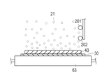
図1〜3に示すように、電極乾燥装置10は、溶媒21を含む電極スラリー20を電極箔30(集電体に相当する)に塗布することによって形成された電極層40を乾燥炉50の中において乾燥させる装置である。この電極乾燥装置10は、電極層40が形成された電極箔30を乾燥炉50内において搬送する搬送部60と、電極層40を乾燥させる熱を付与する加熱部80と、加熱された空気を乾燥炉50内に送風する送風部70と、加熱部80とは異なる追加加熱部90と、を有している。さらに、電極乾燥装置10は、複数の計測手段を備えており、電極層40の温度を計測する電極温度検出部100と、乾燥炉50内の風速を計測する風速検出部110と、炉内の雰囲気温度を計測する炉内温度検出部120と、蒸発した溶媒の濃度を計測する溶媒濃度検出部130と、を有している。電極乾燥装置10は、構成する各部位が制御部160によって統括的に制御される。以下、詳述する。
As shown in FIGS. 1 to 3, the
電極箔30は、集電体として用いられる。電極箔30は、適宜の材料、例えば、アルミニウム、銅、ニッケル、鉄、ステンレス鋼を用いることができる。具体的には、例えば、正極集電体にはアルミニウムなどの電極箔30を用い、負極集電体には銅などの電極箔30を用いることができる。電極箔30の具体的な厚さについて特に制限はないが、例えば、アルミニウムの場合には20μm、銅の場合には10μ程度の薄膜である。
The
電極スラリー20には、正極を形成するために用いる正極スラリーと、負極を形成するために用いる負極スラリーとがある。
The
正極スラリーは、例えば、正極活物質22、導電助剤24、およびバインダー23を有し、溶媒21を添加することで、所定の粘度にされる。正極活物質22は、例えば、マンガン酸リチウムである。導電助剤24は、例えば、アセチレンブラックである。バインダー23は、例えば、PVDF(ポリフッ化ビニリデン)である。溶媒21は、例えば、NMP(ノルマルメチルピロリドン)である。なお、正極活物質22は、マンガン酸リチウムに特に限定されないが、容量および出力特性の観点から、リチウム−遷移金属複合酸化物を適用することが好ましい。導電助剤24は、例えば、カーボンブラックやグラファイトを利用することも可能である。バインダー23および溶媒21は、PVDFおよびNMPに限定されない。溶媒21として水を用いることもできる。
The positive electrode slurry has, for example, a positive electrode
負極スラリーは、例えば、負極活物質22、導電助剤24、およびバインダー23を有し、溶媒21を添加することで、所定の粘度にされる。負極活物質22は、例えば、グラファイトである。導電助剤24、バインダー23、および溶媒21は、例えば、アセチレンブラック、PVDF、およびNMPである。なお、負極活物質22は、グラファイトに特に限定されず、ハードカーボンや、リチウム−遷移金属複合酸化物を利用することも可能である。導電助剤24は、例えば、カーボンブラックやグラファイトを利用することも可能である。バインダー23および溶媒21は、PVDFおよびNMPに限定されない。
溶媒21として水を用いることもできる。
The negative electrode slurry has, for example, a negative electrode
Water can also be used as the solvent 21.
電極箔30に正極スラリーを塗布することによって形成した正極の電極層40および負極スラリーを塗布することによって形成した負極の電極層40を、乾燥炉50において乾燥し、正極および負極を形成する。このとき、電極スラリー20に含まれる溶媒21としてのNMPは、蒸発することによって電極スラリー20から除去する。
The
電極乾燥装置10の乾燥炉50は、熱風通路および電極箔30の搬送路を形成するケーシング140を有している。乾燥炉50内は、複数(図示例にあっては、6個)に区画した乾燥ゾーン51〜56から構成されている。説明の便宜上、電極箔30を搬送する方向(以下、搬送方向という場合がある。)の上流側から順に(図1において左側から順に)、第1の乾燥ゾーン51、第2の乾燥ゾーン52、第3の乾燥ゾーン53、第4の乾燥ゾーン54、第5の乾燥ゾーン55、および第6の乾燥ゾーン56という。ケーシング140内に仕切り壁141を設けることによって、第1〜第6のそれぞれの乾燥ゾーン51〜56を形成している。搬送部60を配置するために、ケーシング140の端面、および仕切り壁141には開口部を設けている。第1〜第6の乾燥ゾーン51〜56のそれぞれには、搬送される電極箔30の上方位置から熱風を供給するための上ノズル142と、搬送される電極箔30の下方位置から熱風を供給するための下ノズル143と、乾燥ゾーン51〜56内から排気管190を介して排気するための排気口144とを設けている。
The drying
そして、各々の乾燥ゾーン51〜56ごとに、加熱部80、送風部70、追加加熱部90を設けている。さらに、各々の乾燥ゾーン51〜56ごとに、電極温度検出部100、風速検出部110、炉内温度検出部120、および溶媒濃度検出部130を設けている。
And the
上ノズル142および下ノズル143は、熱風供給管150が接続されており、熱風供給管150には、加熱部80と、送風部70とが接続されている。加熱部および送風部70は、制御部160に接続されており、加熱温度および送風量を任意に制御可能となっている。送風部70には、外部から空気を取り込む吸気管170と、乾燥ゾーン51〜56内の空気を再利用するための循環管180とが接続されており、循環管180に設けられるバルブ181が開閉することで、循環管180から排出された空気を、吸気管170からの空気と任意の割合で混合して再び利用することができる。排気を再利用することで、低コストでの量産が可能となる。
A hot
送風部70は、送風用のファン71を有している。加熱部80は、熱交換器であり、熱媒体(例えば、蒸気や蒸気還流水)との間で熱交換を行って空気を加熱する。なお、加熱部80は、空気を加熱できるのであれば熱交換器でなくてもよい。熱風の温度は、環境温度や電極スラリー20の種類などによって種々異なることから特に限定されないが、例えば100±40℃である。
The
追加加熱部90は、搬送される電極箔30の上方位置から電極層40へ赤外線を照射する照射部91と、照射部91を覆うことが可能なシャッター92とを備えている。シャッター92は、モータ等の駆動源によって開閉可能であり、閉じた状態では、照射部91からの赤外線が電極層40へ照射されず、開いた状態となることで、搬送方向と直交する幅方向(図1、図3の紙面奥行方向。以下、幅方向という場合がある。)に延びる一定間隔のスリット93を形成する(図8参照)。スリット93を通して照射された赤外線は、電極層40を加熱するが、この際、スリット93の延びる方向(幅方向)には均一な照射率となり、スリット93の隙間方向(搬送方向)には、中央部を頂点として両方向へ照射率が減少する。
The
溶媒濃度検出部130は、蒸発した溶媒を捕集するための捕集管131(排気経路)と、捕集管131へ向かう流れを乾燥炉50内に形成する捕集用ノズル132と、捕集管131内に設けられる溶媒濃度計134と、を有している。捕集管131および捕集用ノズル132は、間に電極層40を挟むように幅方向に対向して配置される。捕集用ノズル132は、バルブ151を有する熱風供給管150に接続されることで、加熱された空気を吐出でき、電極層40の上面に沿う空気の流れを形成して、捕集管131へ空気を導入させる。捕集管131は、捕集した空気を排気管190まで導く。溶媒濃度計134は、捕集された空気に含まれる溶媒の濃度を検出し、検出した信号を制御部160へ送信する。
The solvent
電極温度検出部100は、例えば放射式温度計であり、離間した位置から電極層40の温度を検出し、検出した信号を制御部160へ送信する。
The electrode
風速検出部110は、乾燥炉内の風速を検出し、検出した信号を制御部160へ送信する。
The wind
炉内温度検出部120は、例えば熱電対や抵抗温度計等であり、乾燥炉50内の雰囲気温度を検出して、検出した信号を制御部160へ送信する。
The furnace
搬送部60は、電極スラリー20を塗布する前の電極箔30を供給する供給ロール61と、電極層40を乾燥させた後の電極箔30を巻き取る巻取りロール62と、供給ロール61と巻取りロール62との間に配置され電極箔30の下面を保持する複数のサポートロール63と、を有している。供給ロール61には、電極箔30を予め巻回してある。巻取りロール62には、巻取りロール62を回転駆動するモータMを接続してある。モータMを駆動して巻取りロール62を回転駆動すると、電極箔30は、供給ロール61から繰り出され、乾燥炉50内を搬送され、巻取りロール62に巻き取られる。このようにして、搬送部60は、長尺状の電極箔30をロール・トゥ・ロール方式によって連続的に搬送する。
The
電極スラリー20の塗布は、電極箔30を搬送しつつ、塗布部145によって行う。塗布部145は、溶媒21を含むスラリー状の電極スラリー20を電極箔30に塗布するコーター146を有している。コーター146は、電極箔30に対向し、電極箔30を搬送しながら間欠的に電極スラリー20を塗布する。これにより、電極スラリー20は、一定の間隔の隙間を空けて間欠的に配列する。コーター146を使っての間欠塗工方式では、ロール・トゥ・ロール方式で供給される集電箔に、電極スラリー20を、膜厚30〜300μm程度で均一に塗工し、連続生産を行う。
Application | coating of the
制御部160は、CPUおよびメモリを主体として構成され、動作を制御するためのプログラムがメモリに記憶されている。制御部160は、塗布部145の作動を制御して、電極スラリー20の塗布量、塗布厚さなどを調整し、各々の乾燥ゾーン51〜56ごとに加熱部80および送風部70の作動を制御して、給気の温度、風量などを調整する。制御部160はまた、モータMの作動を制御して、電極箔30の搬送速度を調整する。
The
さらに、制御部160は、溶媒濃度検出部130、炉内温度検出部120、風速検出部110および電極温度検出部100から送信される信号から、溶媒蒸発量Mを算出する。すなわち、炉内における溶媒蒸発量Mは、雰囲気中の溶媒濃度、炉内温度、炉内の風速、および電極層40の温度の条件により決定されるため、これらの乾燥因子の計測値に基づいて、電極層40から蒸発した溶媒21の総量である溶媒蒸発量Mを算出する。なお、溶媒蒸発量Mは、雰囲気中の溶媒濃度が低く、炉内温度が高く、炉内の風速が高く、かつ電極層40の温度が高いほど上昇する。これらの乾燥因子に基づく溶媒蒸発量Mは、実験的に求めることができる。
Furthermore, the
また、制御部160には、図5に示すように、時間に対する溶媒蒸発量の軌跡で定義される乾燥基準値A1を予め記憶させる。そして、制御部160は、計測される乾燥因子から算出される溶媒蒸発量Mが乾燥基準値A1の範囲内に常に収まるように、加熱部80、追加加熱部90および送風部70を自動で調整する。加熱部80、追加加熱部90による加熱量を増加させ、かつ送風部70による送風量を上昇させるほど、溶媒蒸発量Mは上昇することになる。
Further, as shown in FIG. 5, the
なお、本実施形態では、乾燥基準値A1は、図5に示すように、溶媒蒸発量が幅を有する帯状の範囲で定義されているが、幅を有しない線で定義して、算出される溶媒蒸発量Mが線に極力追従するように制御してもよい。乾燥基準値A1は、実験等によって決定される。 In the present embodiment, the drying reference value A1 is defined as a band-shaped range having a width as shown in FIG. 5, but is defined and calculated by a line having no width. The solvent evaporation amount M may be controlled so as to follow the line as much as possible. The drying reference value A1 is determined by experiments or the like.
そして、乾燥基準値は、乾燥に必要な時間に応じて、複数(本実施形態では2つ)設けられる。図6は、図5に示す乾燥基準値A1よりも長い時間をかけて乾燥させる場合の乾燥基準値A2を示している。 A plurality (two in this embodiment) of reference drying values are provided according to the time required for drying. FIG. 6 shows a drying reference value A2 when drying is performed over a longer time than the drying reference value A1 shown in FIG.
本実施形態の作用を説明する前に、乾燥炉50に供給する給気の温度や風量が適切でないときに生じる不具合について説明する。
Before describing the operation of the present embodiment, a problem that occurs when the temperature and air volume of the supply air supplied to the drying
熱風を用いた乾燥炉50において乾燥速度の向上を図る場合には、熱風温度を高くするとともに風量を増加し、電極層40の表面と雰囲気57との界面部分における溶媒21(NMP)の除去量を増加させる。このような対応の場合、乾燥が早くなって、電極層40の表面近傍にバインダー23(PVDF)が偏析してしまう。このため、電極箔30に強く密着した塗膜つまり強密着の電極層40を得ることができなくなる。
When the drying rate is improved in the drying
熱風温度を高くした場合にバインダー23の偏析が生じる原因として、次のようなものを挙げることができる。すなわち、乾燥時においてはバインダー23を溶媒21に溶かしたものが電極層40に含まれているので、電極層40を高い温度の環境下にさらすと、電極層40内において溶媒21自体が対流を起こす。その結果、溶解しているバインダー23が偏析してしまう。
The following can be cited as causes of segregation of the
また、風量を増加した場合にバインダー23の偏析が生じる原因として、次のようなものを挙げることができる。すなわち、電極層40の表面近傍における溶媒21(NMP)だけが優先的に蒸発して表面近傍だけが先に乾き(表面先乾き)、この表面先乾き部分に生じた亀裂やホールなどによる毛細管現象によって、NMPを深部から表面に向けて吸い上げる。その結果、溶解しているバインダー23が偏析してしまう。
Moreover, the following can be mentioned as a cause of the segregation of the
乾燥時にバインダー23の偏析を生じ得る乾燥条件では、表面粗さが大きく、密着力も弱いことから、電極箔30と電極層40との接触量あるいは接触面積が少なくなる。このため、初期における電池内の抵抗値のみならず、充放電を繰り返した後の電池内の抵抗値も高くなり、電極性能の低下を招くことになる。
Under drying conditions that can cause segregation of the
発生したバインダー23の偏析を解消するために、乾燥後の電極をロールプレス機などによって圧縮する方法がある。しかしながら、乾燥が完了して電極層40が固着した後に強制的に構造変化させることになるため、電極層40の密着強度はさほど向上しない。しかも、低コストで量産を実現する観点から、乾燥工程の後に圧縮工程を付加することは避けることが望ましい。
In order to eliminate the segregation of the generated
次に、本実施形態の作用を説明する。 Next, the operation of this embodiment will be described.
モータMを駆動して巻取りロール62を回転駆動し、電極箔30を、供給ロール61から繰り出し、巻取りロール62に巻き取る。コーター146は、移動している電極箔30の表面に間欠的に電極スラリー20を塗布する。制御部160は、塗布部145の作動を制御し、電極スラリー20の塗布量、塗布厚さなどを調整している。加熱部80および送風部70は、熱風を、上下のノズル142,143から熱風通路内に供給する。電極箔30の表面に溶媒21を含む電極スラリー20を塗布した後、電極層40を第1の乾燥ゾーン51〜第6の乾燥ゾーン56へ順次搬送しつつ、各々の乾燥ゾーン51〜56の乾燥炉50内において、電極層40に含まれる溶媒21を蒸発させる。
The motor M is driven to rotationally drive the take-
また、各々の乾燥炉50内において、捕集用ノズル132からは、熱風供給管150から供給される加熱された空気を吐出し、電極層40の上面に沿う空気の流れを形成して、捕集管131へ空気を導入させる。空気の流れは、例えば、図7(A)に示すように電極層40に沿う層流としたり、または図7(B)に示すように直進性を有する渦状とすることができる。捕集管131は、捕集した空気を溶媒濃度計134に導いた後、排気管190へ排出する。このように、捕集用ノズル132および捕集管131を設けることで、電極層40から蒸発した溶媒を効果的に捕集することができ、溶媒21の蒸発に影響する電極層40の近傍の溶媒濃度を、溶媒濃度計134によって正確に計測できる。
Further, in each drying
そして、各々の乾燥ゾーン51〜56において、溶媒濃度検出部130、炉内温度検出部120、風速検出部110および電極温度検出部100により、雰囲気中の溶媒濃度、炉内温度、炉内の風速、および電極層40の温度を逐次検出し、検出した信号を制御部160に送信する。制御部160は、受信した信号から、搬送中の電極層40からの溶媒蒸発量Mを、逐次算出する。このように、乾燥炉50内における溶媒蒸発量Mは、雰囲気中の溶媒濃度、炉内温度、炉内の風速、および電極層40の温度の条件により決定されるため、これらの乾燥因子を計測することで、電極層40から蒸発した溶媒蒸発量Mを算出することができる。なお、炉内温度と電極層40の温度を略同一と近似して、一方のみを計測して溶媒蒸発量Mの算出に利用することもできる。
In each of the drying
そして、制御部160は、計測される乾燥因子から算出される溶媒蒸発量Mが、予め設定されている乾燥基準値A1の範囲内に常に収まるように、加熱部80および送風部70を制御して自動で調整する。
Then, the
そして、電極層40を第1の乾燥ゾーン51〜第6の乾燥ゾーン56へ順次搬送しつつ、各々の乾燥ゾーン51〜56の乾燥炉50内において、算出される溶媒蒸発量Mが予め設定されている乾燥基準値A1の範囲内に常に収まるように、電極層40に含まれる溶媒21を蒸発させる。このように、乾燥因子である雰囲気中の溶媒濃度、炉内温度、炉内の風速、および電極層40の温度を常に監視して溶媒蒸発量Mを乾燥基準値A1内に調整することで、時間の経過に応じて変化する乾燥基準値A1に追従するように、望ましい溶媒蒸発量Mを維持することができる。このため、剥離強度が強く性能の高い電極を安定して製造することができる。
The calculated solvent evaporation amount M is set in advance in the drying
そして、乾燥工程にかける時間を変更する必要が生じると、乾燥基準値A1を、図6に示す他の乾燥基準値A2に切り換える。 When the time required for the drying process needs to be changed, the drying reference value A1 is switched to another drying reference value A2 shown in FIG.
電極の製造工程には、電極スラリー20の固形分を溶媒21に分散する工程、電極スラリー20を電極箔に塗布する工程、電極スラリー20の乾燥工程、乾燥した電極層40をプレスする工程、そして電極を所定の形状に切断する工程が含まれており、これらの工程を連続的に行うことで、電極の高い生産速度を発揮する。しかしながら、各工程は個々の生産速度を有しており、工程間に、材料や生産物の受け渡しに伴う待ち時間や清掃時間等が発生する。しかしながら、電極乾燥装置10は、一旦停止させると再び起動するのに時間がかかるため、電極乾燥装置10が、停止させることなしに生産時間の増減を吸収できる能力を備えることが望ましい。そして、乾燥時間の異なる複数の乾燥基準値A1,A2を設けることで、乾燥時間を自在に変更可能とし、前後の工程との間での生産時間の増減を吸収することが可能となる。
The electrode manufacturing process includes a step of dispersing the solid content of the
したがって、例えば、容器に入れて一定量ずつ供給される電極スラリー20の容器を交換する場合に、電極乾燥装置10を停止させずに、乾燥基準値A2に切り換えて電極乾燥工程にかける時間を変更し、容器を交換する時間を稼ぐことができる。
Therefore, for example, when replacing the container of the
乾燥基準値A2に切り換わると、制御部160は、モータMを制御して搬送速度を変更する。
When switching to the drying reference value A2, the
そして、制御部160は、計測される乾燥因子から算出される溶媒蒸発量Mが、予め設定されている乾燥基準値A2の範囲内に常に収まるように、加熱部80および送風部70を制御して自動で調整する。そして、電極層40を第1の乾燥ゾーン51〜第6の乾燥ゾーン56へ順次搬送しつつ、各々の乾燥ゾーン51〜56の乾燥炉50内において、算出される溶媒蒸発量Mが、変更された乾燥基準値A2の範囲内に常に収まるように、電極層40に含まれる溶媒21を蒸発させる。
Then, the
そして、乾燥基準値A2への切り換えに伴い、いずれかの乾燥ゾーン51〜56において炉内温度を上昇させる必要が生じた場合、加熱部80による加熱は乾燥炉50内の全体を昇温させるために時間を要することから、加熱部80による加熱量を上昇させつつ、追加加熱部90をも作動させる。追加加熱部90は、シャッター92を閉じた状態で照射部91を作動させておくことで、図8に示すようにシャッター92を開くと同時に、電極層40を迅速に加熱することができる。シャッター92を開くと、スリット93から赤外線が照射されるが、この際、スリット93の延びる方向(幅方向)に均一な照射率となっているため、電極層40を幅方向に均一に加熱することができる。また、スリット93から照射される赤外線は、スリット93の隙間方向(搬送方向)には、中央部を頂点として両方向(搬送方向の上流方向および下流方向)へ照射率が減少するため、搬送方向へ移動する電極層40が赤外線の照射範囲に入る際に、急激に加熱されず、溶媒の乾燥を良好に維持することができる。この後、加熱部80による加熱によって乾燥炉50内の温度が全体的に上昇するに従い、追加加熱部90による加熱量を低減させ、最終的に追加加熱部90を停止させる。
And when it becomes necessary to raise the furnace temperature in any one of the drying
このように、乾燥因子である雰囲気中の溶媒濃度、炉内温度、炉内の風速、および電極層40の温度を常に監視して溶媒蒸発量Mを乾燥基準値A2内に調整することで、乾燥時間が変更されても、乾燥基準値A2に追従するように、望ましい溶媒蒸発量Mを維持することができる。このため、常に望ましい乾燥状態を維持できるため、バインダー23の偏析が生じることを防止できる。バインダー23の偏析を生じさせない条件にて電極層40を乾燥させているので、電極箔30と電極層40との密着性が向上し、電極箔30と電極層40との接触量あるいは接触面積が十分大きくなる。このため、初期における電池内の抵抗値はもちろんのこと、充放電を繰り返した後の電池内の抵抗値も低くなり、電極性能の向上を図ることが可能となる。
In this way, by constantly monitoring the solvent concentration in the atmosphere, which is a drying factor, the temperature in the furnace, the wind speed in the furnace, and the temperature of the
そして、電極スラリー20の容器の交換が終了すると、乾燥時間の短い(乾燥速度の速い)元の乾燥基準値A1に戻して、電極の乾燥を行うことになる。この際においても、いずれかの乾燥ゾーン51〜56において炉内温度を上昇させる必要が生じた場合、加熱部80による加熱量を上昇させるとともに、追加加熱部90を作動させる。そして、加熱部80による加熱によって乾燥炉50内の温度が全体的に上昇するに従い、追加加熱部90による加熱量を低減させ、最終的に追加加熱部90を停止させる。
When the replacement of the
<実験例>
炉内の搬送方向の長さX(m)の乾燥炉を用いて、搬送速度0.5X(m/分)で乾燥実験を行った。乾燥炉内は複数の乾燥ゾーンに区分けし、乾燥ゾーンごとに温度および風速を個別に設定できるようにした。各乾燥ゾーンに、溶媒濃度検出部、炉内温度検出部、風速検出部および電極温度検出部を設けて、雰囲気中の溶媒濃度、炉内温度、炉内の風速、および電極層の温度を監視して記録した。そして、計測される乾燥因子に基づいて溶媒蒸発量を算出し、溶媒蒸発量の時間変化の軌跡を求めた。この際、乾燥因子を変化させるように設備条件を変更し、表1の実験例1〜5に示すように、複数の溶媒蒸発量の時間変化の軌跡を得た。そして、実験例1〜5の条件で電極を作製し、剥離強度と、充放電を100回繰り返した後の電池内の抵抗値を評価した。結果を表1に示す。
<Experimental example>
Using a drying furnace having a length X (m) in the conveying direction in the furnace, a drying experiment was performed at a conveying speed of 0.5 X (m / min). The inside of the drying furnace was divided into a plurality of drying zones, and the temperature and wind speed could be set individually for each drying zone. Each drying zone is equipped with a solvent concentration detector, furnace temperature detector, wind speed detector, and electrode temperature detector to monitor the solvent concentration, furnace temperature, furnace wind speed, and electrode layer temperature in the atmosphere. And recorded. Then, the amount of solvent evaporation was calculated based on the measured drying factor, and the time course of the solvent evaporation amount was obtained. At this time, the equipment conditions were changed so as to change the drying factor, and as shown in Experimental Examples 1 to 5 in Table 1, a plurality of time courses of solvent evaporation were obtained. And the electrode was produced on the conditions of Experimental Examples 1-5, and the resistance value in a battery after repeating peeling strength and charging / discharging 100 times was evaluated. The results are shown in Table 1.

結果として、実験例1および実験例5は、剥離強度が低く抵抗値が高くなっており、電池としての品質を満たさなかった。これに対し、実験例2〜実験例4は、剥離強度が高く抵抗値が低くなっており、電池としての品質を満たした。このように、作製される電池が良好な性能を示す溶媒蒸発量の軌跡を複数得ることができた。したがって、実験例2〜実験例4の条件の範囲で、電池の品質が成立するための乾燥基準値を設定することが可能となった。 As a result, in Experimental Example 1 and Experimental Example 5, the peel strength was low and the resistance value was high, and the quality as a battery was not satisfied. On the other hand, Experimental Example 2 to Experimental Example 4 had high peel strength and low resistance, satisfying the quality as a battery. As described above, it was possible to obtain a plurality of solvent evaporation trajectories in which the produced battery exhibited good performance. Therefore, it is possible to set a drying reference value for establishing the quality of the battery within the range of the conditions of Experimental Example 2 to Experimental Example 4.
次に、同一の乾燥炉を用いて、搬送速度を先の実験の半分の0.25X(m/分)で乾燥実験を行った。なお、搬送速度以外は、先の実験と同一の乾燥条件とした。そして、各乾燥ゾーンでの溶媒蒸発量が実験例1〜5と同様となるように、乾燥ゾーンごとに温度および風速を制御して、実験例6〜10の結果を得た。すなわち、実験例6〜10は、実験例1〜5より得られた溶媒蒸発量の軌跡を乾燥基準値として用いて、電極を作製したものである。結果を表2に示す。 Next, using the same drying furnace, a drying experiment was performed at a conveyance speed of 0.25 × (m / min), which is half of the previous experiment. The drying conditions were the same as in the previous experiment except for the conveyance speed. And the temperature and wind speed were controlled for every drying zone so that the amount of solvent evaporation in each drying zone might become the same as that of Experimental Examples 1-5, and the result of Experimental Examples 6-10 was obtained. That is, in Experimental Examples 6 to 10, the electrodes were produced using the trajectory of the solvent evaporation amount obtained from Experimental Examples 1 to 5 as the drying reference value. The results are shown in Table 2.
結果として、実験例1および実験例5に対応する実験例6および実験例10は、剥離強度が低く抵抗値が高くなっており、電池としての品質を満たさなかった。これに対し、実験例2〜実験例4に対応する実験例7〜実験例9は、剥離強度が高く抵抗値が低くなっており、電池としての品質を満たした。このように、搬送速度が変化して、炉内の各乾燥ゾーンを通過する時間が変化しても、品質が成立する乾燥基準値を用いることで、好ましい電極を得られることが確認された。 As a result, in Experimental Example 6 and Experimental Example 10 corresponding to Experimental Example 1 and Experimental Example 5, the peel strength was low and the resistance value was high, and the quality as a battery was not satisfied. On the other hand, Experimental Example 7 to Experimental Example 9 corresponding to Experimental Example 2 to Experimental Example 4 had high peel strength and low resistance value, satisfying the quality as a battery. Thus, it was confirmed that a preferable electrode can be obtained by using a drying reference value that establishes quality even if the transport speed changes and the time for passing through each drying zone in the furnace changes.
以上説明したように、本実施形態によれば、時間に対する電極層40からの溶媒21の蒸発量の軌跡で定義される乾燥基準値A1,A2を予め設定し、乾燥炉50内の温度、風速および溶媒濃度を含む乾燥因子を検出して当該乾燥因子に基づいて溶媒蒸発量Mを算出する。そして、当該溶媒蒸発量Mが乾燥基準値A1,A2に追従するように、加熱部80および送風部70を制御しつつ電極層40を乾燥させている。したがって、電極層40の連続的な乾燥状態を把握しつつ、望ましい乾燥条件を設定することができる。このため、連続的に設けられる望ましい乾燥条件で電極層40を乾燥させるので、バインダー23の偏析が生じることを防止できる。バインダー23の偏析を生じさせない条件にて電極層40を乾燥させているので、電極箔30と電極層40との密着性が向上し、初期における電池内の抵抗値はもちろんのこと、充放電を繰り返した後の電池内の抵抗値も低くなり、電極性能の向上を図ることが可能となる。
As described above, according to the present embodiment, the drying reference values A1 and A2 defined by the trajectory of the evaporation amount of the solvent 21 from the
乾燥炉50内に電極層40を保持する乾燥時間を変更する場合に、乾燥因子に基づいて算出される溶媒蒸発量Mが、変更した後の乾燥時間に対応する既定の乾燥基準値A1,A2に追従するように、加熱部80および送風部70を制御する。したがって、乾燥時間を自在に変更可能とし、前後の工程との間での生産時間の増減を吸収することが可能となる。
When the drying time for holding the
乾燥炉50内に電極層40を保持する乾燥時間を変更する場合に、加熱部80に加えて加熱部80と異なる追加加熱部90を用いて電極層40を加熱する。このため、電極層40を迅速に加熱することが可能となり、変更された乾燥条件へ迅速に移行することができる。
When the drying time for holding the
乾燥炉50内に電極層40を保持する乾燥時間を変更する場合に、加熱部80による加熱量を増加させつつ追加加熱部90を作動させた後、追加加熱部90による加熱量を徐々に減少させる。このため、追加加熱部90を用いて変更された乾燥条件へ迅速に対応した後、加熱部80による加熱が効果を発揮するにつれて追加加熱部90による加熱を減少させることができ、望ましい乾燥条件を維持することができる。
When changing the drying time for holding the
電極層40から蒸発した溶媒21を排気するための専用の捕集管131(排気経路)を設け、捕集管131に溶媒濃度検出部130を配置して溶媒の濃度を検出する。このため、電極層40から蒸発した溶媒21を効果的に捕集でき、溶媒21の蒸発に影響する電極層40の近傍の溶媒濃度をより正確に検出できる。
A dedicated collection tube 131 (exhaust path) for exhausting the solvent 21 evaporated from the
乾燥炉50内に専用の捕集管131(排気経路)へ向かう流体の流れを生じさせて捕集管131へ蒸発した溶媒21を導くため、蒸発した溶媒21をより効果的に捕集できる。
Since the flow of the fluid which goes to the exclusive collection pipe | tube 131 (exhaust path | route) is produced in the drying
専用の捕集管131(排気経路)へ向かう流体の流れを生じさせる捕集用ノズル132を設け、捕集用ノズル132により捕集管131へ蒸発した溶媒21を導くため、望ましい流れを容易に形成でき、蒸発した溶媒21をより効果的に捕集できる。
A
(改変例)
乾燥炉50内を複数(6つ)の乾燥ゾーン51〜56に区画した実施形態を示したが、乾燥ゾーンは6つでなくてもよく、または1つだけの乾燥炉にも本発明を適用することはできる。
(Modification example)
Although the embodiment in which the inside of the drying
追加加熱部90は、赤外線の照射範囲が線状であると、照射範囲内のみで乾燥速度が急激に上昇しやすいため、照射率が電極層40の搬送方向に向かって徐々に変化するように、赤外線の透過率を設定できる赤外線反射膜を介して赤外線を照射してもよい。または、シャッター92を構成する材料に、赤外線反射膜を用いることもできる。
In the
また、図9に示すように、溶媒濃度検出部を捕集管に設けるのではなく、乾燥炉50内において電極層40からの距離が異なる複数個所に溶媒濃度検出部200,201を配置してもよい。このとき、溶媒濃度検出部200は、電極層40の上方に形成される気液境界層の上部に位置し、溶媒濃度検出部201は、電極層40の気液境界層の下部に位置している。これにより、複数の溶媒濃度検出部200,201による検出結果を平均化することで、場所による溶媒の濃度の偏りに左右されずに、正確な溶媒蒸発量Mを算出することができる。また、当然に、捕集管に設けられない1つの溶媒濃度検出部のみで構成することもできる。
In addition, as shown in FIG. 9, the solvent concentration detectors are not provided in the collection tube, but the
また、追加加熱部は、赤外線を照射する構成に限定されない。例えば、図10に示すように、サポートロール211に、サポートロール211自体を加熱する加熱源212と、サポートロール211内に冷媒を循環させてサポートロール211を冷却させる冷却手段213と、を設けた追加加熱部210とすることができる。加熱源212は、加熱可能であれば構成は限定されず、例えば電熱線、赤外線、熱交換器、または電磁誘導加熱等を利用できる。このような構成とすることで、サポートロール211に直接接する電極箔30を介して、電極層40を加熱することができる。また、冷却手段213が設けられることで、追加加熱部210による加熱が不要となった場合に、サポートロール211を迅速に冷却でき、目的の温度への追従性が向上する。また、加熱源212に電磁誘導加熱を利用する場合には、サポートロール211を加熱するのではなしに、金属製の電極箔30を直接加熱する構成としてもよい。
Moreover, an additional heating part is not limited to the structure which irradiates infrared rays. For example, as shown in FIG. 10, the support roll 211 is provided with a
また、図11に示すように、加熱部80と並列に設けられて、加熱部80と同様に乾燥炉50内へ送風される空気を加熱する追加加熱部220を設けてもよい。追加加熱部220は、制御部160によってバルブ221を開閉することで、熱風供給管150への熱風の供給および停止を切り換え可能である。
As shown in FIG. 11, an
また、各乾燥ゾーン51〜56には、同様の構成の追加加熱部90を設けているが、各乾燥ゾーン51〜56に、異なる構成の追加加熱部を設けてもよい。
Moreover, although the
また、電極箔30を連続して搬送する形態を図示したが、バッチ式で搬送する形態でもよい。
Moreover, although the form which conveys the
さらに、本発明は、電極スラリー20を間欠的に塗布する場合に限られるものではなく、電極スラリー20を連続塗布する場合にも適用できることは言うまでもない。
Further, the present invention is not limited to the case where the
10 電極乾燥装置、
20 電極スラリー、
21 溶媒、
40 電極層、
50 乾燥炉、
51〜56 第1〜第2の乾燥ゾーン、
60 搬送部、
70 送風部、
80 加熱部、
90,210 追加加熱部、
100 電極温度検出部、
110 風速検出部、
120 炉内温度検出部、
130,200,201 溶媒濃度検出部、
131 捕集管(専用の排気経路)、
132 捕集用ノズル、
134 溶媒濃度計、
145 塗布部、
160 制御部、
A1,A2 乾燥基準値、
M 溶媒蒸発量。
10 electrode drying device,
20 electrode slurry,
21 solvent,
40 electrode layers,
50 drying ovens,
51-56 first and second drying zones,
60 transport section,
70 Blower,
80 heating section,
90,210 Additional heating section,
100 electrode temperature detector,
110 wind speed detector,
120 furnace temperature detector,
130, 200, 201 solvent concentration detector,
131 Collection pipe (exclusive exhaust route),
132 Nozzle for collection,
134 solvent concentration meter,
145 application part,
160 control unit,
A1, A2 dry standard value,
M Solvent evaporation.
Claims (13)
時間に対する前記電極層からの溶媒の蒸発量の軌跡で定義される乾燥基準値を予め設定し、前記乾燥炉内の温度、風速および溶媒濃度を含む乾燥因子を検出して当該乾燥因子に基づいて前記溶媒の蒸発量を算出し、当該溶媒の蒸発量が前記乾燥基準値に追従するように、前記乾燥炉内を加熱する加熱部および前記乾燥炉内に送風する送風部を制御しつつ前記電極層を乾燥させ、
前記乾燥炉内に前記電極層を保持する乾燥時間を変更する場合に、前記乾燥因子に基づいて算出される前記溶媒の蒸発量が、変更した後の乾燥時間に対応する既定の乾燥基準値に追従するように、前記加熱部および送風部を制御する、電極乾燥方法。 An electrode drying method for drying an electrode layer formed by applying an electrode slurry containing a solvent to a current collector in a drying furnace,
A drying reference value defined by a trajectory of the amount of solvent evaporation from the electrode layer with respect to time is set in advance, and a drying factor including temperature, wind speed, and solvent concentration in the drying furnace is detected and based on the drying factor. Calculate the evaporation amount of the solvent, and control the heating unit that heats the inside of the drying furnace and the blowing unit that blows air into the drying furnace so that the evaporation amount of the solvent follows the drying reference value. Dry the layer ,
When changing the drying time for holding the electrode layer in the drying furnace, the evaporation amount of the solvent calculated based on the drying factor becomes a predetermined drying reference value corresponding to the changed drying time. An electrode drying method for controlling the heating unit and the air blowing unit so as to follow .
前記乾燥炉内の温度を検出する温度検出部と、 A temperature detector for detecting the temperature in the drying furnace;
前記乾燥炉内の風速を検出する風速検出部と、 A wind speed detector for detecting the wind speed in the drying furnace;
前記乾燥炉内の雰囲気の溶媒濃度を検出する溶媒濃度検出部と、 A solvent concentration detection unit for detecting the solvent concentration of the atmosphere in the drying furnace;
前記乾燥炉内を加熱する加熱部と、 A heating unit for heating the inside of the drying furnace;
前記乾燥炉内に送風する送風部と、 An air blower for blowing air into the drying furnace;
前記温度検出部、風速検出部および溶媒濃度検出部から検出された信号を受信し、検出値に基づいて前記溶媒の蒸発量を算出し、当該溶媒の蒸発量が、時間に対する前記電極層からの溶媒の蒸発量の軌跡で定義される予め設定された乾燥基準値に追従するように、前記加熱部および前記送風部を制御する制御部と、を有し、 Receiving signals detected from the temperature detection unit, the wind speed detection unit, and the solvent concentration detection unit, calculate the evaporation amount of the solvent based on the detection value, the evaporation amount of the solvent from the electrode layer with respect to time A control unit that controls the heating unit and the blower unit so as to follow a preset drying reference value defined by a trajectory of the evaporation amount of the solvent,
前記制御部は、前記乾燥炉内に前記電極層を保持する乾燥時間を変更する場合に、前記温度検出部、風速検出部および溶媒濃度検出部から受信した検出値に基づいて算出される前記溶媒の蒸発量が、変更した後の乾燥時間に対応する既定の乾燥基準値に追従するように、前記加熱部および送風部を制御する、電極乾燥装置。 The control unit calculates the solvent calculated based on the detection values received from the temperature detection unit, the wind speed detection unit, and the solvent concentration detection unit when changing the drying time for holding the electrode layer in the drying furnace. The electrode drying apparatus which controls the said heating part and ventilation part so that the evaporation amount of may follow the predetermined drying reference value corresponding to the drying time after changing.
前記制御部は、前記乾燥炉内に前記電極層を保持する乾燥時間を変更する場合に、前記加熱部に加えて前記追加加熱部を作動させる、請求項8に記載の電極乾燥装置。 An additional heating part different from the heating part,
The electrode drying apparatus according to claim 8, wherein the control unit operates the additional heating unit in addition to the heating unit when changing a drying time for holding the electrode layer in the drying furnace .
Priority Applications (2)
| Application Number | Priority Date | Filing Date | Title |
|---|---|---|---|
| JP2011289569A JP5929190B2 (en) | 2011-12-28 | 2011-12-28 | Electrode drying method and electrode drying apparatus |
| KR1020120154479A KR101467640B1 (en) | 2011-12-28 | 2012-12-27 | Method and apparatus for drying electrode |
Applications Claiming Priority (1)
| Application Number | Priority Date | Filing Date | Title |
|---|---|---|---|
| JP2011289569A JP5929190B2 (en) | 2011-12-28 | 2011-12-28 | Electrode drying method and electrode drying apparatus |
Publications (2)
| Publication Number | Publication Date |
|---|---|
| JP2013139889A JP2013139889A (en) | 2013-07-18 |
| JP5929190B2 true JP5929190B2 (en) | 2016-06-01 |
Family
ID=48990237
Family Applications (1)
| Application Number | Title | Priority Date | Filing Date |
|---|---|---|---|
| JP2011289569A Active JP5929190B2 (en) | 2011-12-28 | 2011-12-28 | Electrode drying method and electrode drying apparatus |
Country Status (2)
| Country | Link |
|---|---|
| JP (1) | JP5929190B2 (en) |
| KR (1) | KR101467640B1 (en) |
Families Citing this family (15)
| Publication number | Priority date | Publication date | Assignee | Title |
|---|---|---|---|---|
| KR101867659B1 (en) * | 2012-09-25 | 2018-06-15 | 도요타지도샤가부시키가이샤 | Manufacturing method for secondary battery electrode, and hot air drying furnace |
| JP6052083B2 (en) * | 2013-07-12 | 2016-12-27 | トヨタ自動車株式会社 | Drying apparatus, drying method, and battery manufacturing method |
| JP6252757B2 (en) * | 2014-01-31 | 2017-12-27 | 株式会社豊田自動織機 | Electrode manufacturing method and heating device |
| JP6417810B2 (en) * | 2014-09-17 | 2018-11-07 | 株式会社豊田自動織機 | Drying apparatus and electrode manufacturing method |
| CN106766741B (en) * | 2016-11-25 | 2019-04-12 | 吴保康 | A kind of dampness graphite electrode high efficiency drying equipment |
| JP6280194B1 (en) * | 2016-12-12 | 2018-02-14 | 中外炉工業株式会社 | Paint drying apparatus and paint drying method |
| KR102090043B1 (en) * | 2017-09-12 | 2020-03-17 | 주식회사 엘지화학 | Drying control system of coating layer |
| CN108800773A (en) * | 2018-07-19 | 2018-11-13 | 般若涅利(北京)装备技术有限公司 | A kind of lithium battery electric core vacuum drying oven |
| KR102324681B1 (en) * | 2019-08-22 | 2021-11-10 | 주식회사 스마텍 | Resdual moisture drying apparatus for battery electrode |
| KR102388446B1 (en) * | 2020-06-11 | 2022-04-21 | 주식회사 나래나노텍 | Apparatus and method for drying electrode sheet for battery |
| KR20220028271A (en) * | 2020-08-28 | 2022-03-08 | 주식회사 엘지에너지솔루션 | Apparatus for evaluating drying quality of electrode and method for evaluating drying quality of electrode |
| US20230143349A1 (en) * | 2020-11-27 | 2023-05-11 | Lg Energy Solution, Ltd. | Electrode Drying System and Electrode Drying Method |
| KR20220145029A (en) * | 2021-04-21 | 2022-10-28 | 주식회사 엘지에너지솔루션 | Automated sytstem for drying conditions of electrodes for secondary battery |
| DE102021118534A1 (en) * | 2021-07-19 | 2023-01-19 | Ulf Reinhardt | Drying device and method for drying container units containing solvent |
| WO2024049139A1 (en) * | 2022-08-29 | 2024-03-07 | 주식회사 엘지에너지솔루션 | Method for manufacturing electrode for secondary battery |
Family Cites Families (5)
| Publication number | Priority date | Publication date | Assignee | Title |
|---|---|---|---|---|
| JP3953911B2 (en) * | 2002-08-08 | 2007-08-08 | 松下電器産業株式会社 | Method for producing coating sheet |
| JP4571841B2 (en) * | 2004-09-30 | 2010-10-27 | 大日本印刷株式会社 | Electrode plate manufacturing method |
| JP2007078246A (en) * | 2005-09-14 | 2007-03-29 | Oji Paper Co Ltd | Sheet drying method and device, and method of manufacturing coated sheet |
| KR101286003B1 (en) * | 2006-03-09 | 2013-07-15 | 삼성에스디아이 주식회사 | Method of drying slurry for electrode of rechargeable battery and Apparatus for the same |
| JP5233248B2 (en) * | 2007-11-05 | 2013-07-10 | トヨタ自動車株式会社 | Electrode manufacturing equipment |
-
2011
- 2011-12-28 JP JP2011289569A patent/JP5929190B2/en active Active
-
2012
- 2012-12-27 KR KR1020120154479A patent/KR101467640B1/en active IP Right Grant
Also Published As
| Publication number | Publication date |
|---|---|
| JP2013139889A (en) | 2013-07-18 |
| KR20130076759A (en) | 2013-07-08 |
| KR101467640B1 (en) | 2014-12-01 |
Similar Documents
| Publication | Publication Date | Title |
|---|---|---|
| JP5929190B2 (en) | Electrode drying method and electrode drying apparatus | |
| KR101286003B1 (en) | Method of drying slurry for electrode of rechargeable battery and Apparatus for the same | |
| JP5325332B1 (en) | Battery electrode coating film drying method and drying furnace | |
| US20140014037A1 (en) | Electrode plate production device | |
| CN103165858B (en) | The manufacture method of electrode | |
| JP5909986B2 (en) | Electrode drying method and electrode drying apparatus | |
| JP2012172960A (en) | Drying device and thermal processing system | |
| JP2013137139A (en) | Drying device and heat treatment system | |
| KR20200068650A (en) | Web coating and calendering system and method | |
| CN104662711A (en) | Electricity storage device and electricity storage module | |
| JP2015036590A (en) | Infrared ray processing device and infrared ray processing method | |
| JP5259875B1 (en) | Battery electrode coating film drying method and drying furnace | |
| JP2008103098A (en) | Manufacturing method of electrode plate for nonaqueous electrolyte secondary battery and its manufacturing equipment | |
| JP2012202600A (en) | Drying device and heat treatment system | |
| WO2014129214A1 (en) | Simulation device for drying coating and device for drying coating | |
| JP6011478B2 (en) | Battery electrode plate manufacturing apparatus and battery electrode plate manufacturing method | |
| JP6211461B2 (en) | Electrode material coating system with shutdown function layer | |
| KR101931018B1 (en) | Manufacturing method of electrode and manufacturing apparatus of electrode | |
| JP6423267B2 (en) | Horizontal type double-side coating equipment | |
| JP5887437B2 (en) | Drying equipment and heat treatment system | |
| JP2012013383A (en) | Drying device in thin film coating device | |
| JP2014127438A (en) | Method of manufacturing electrode and dryer | |
| JP2013089573A (en) | Electrode, electrode manufacturing device, and electrode manufacturing method | |
| JP2003178752A (en) | Dried state evaluation method for sheet-shaped electrode | |
| US20240072236A1 (en) | Electrode Manufacturing Apparatus and Method |
Legal Events
| Date | Code | Title | Description |
|---|---|---|---|
| A621 | Written request for application examination |
Free format text: JAPANESE INTERMEDIATE CODE: A621 Effective date: 20141029 |
|
| A977 | Report on retrieval |
Free format text: JAPANESE INTERMEDIATE CODE: A971007 Effective date: 20150807 |
|
| A131 | Notification of reasons for refusal |
Free format text: JAPANESE INTERMEDIATE CODE: A131 Effective date: 20150929 |
|
| A521 | Request for written amendment filed |
Free format text: JAPANESE INTERMEDIATE CODE: A523 Effective date: 20151113 |
|
| TRDD | Decision of grant or rejection written | ||
| A01 | Written decision to grant a patent or to grant a registration (utility model) |
Free format text: JAPANESE INTERMEDIATE CODE: A01 Effective date: 20160405 |
|
| A61 | First payment of annual fees (during grant procedure) |
Free format text: JAPANESE INTERMEDIATE CODE: A61 Effective date: 20160418 |
|
| R151 | Written notification of patent or utility model registration |
Ref document number: 5929190 Country of ref document: JP Free format text: JAPANESE INTERMEDIATE CODE: R151 |
|
| S111 | Request for change of ownership or part of ownership |
Free format text: JAPANESE INTERMEDIATE CODE: R313111 |
|
| R350 | Written notification of registration of transfer |
Free format text: JAPANESE INTERMEDIATE CODE: R350 |
|
| R250 | Receipt of annual fees |
Free format text: JAPANESE INTERMEDIATE CODE: R250 |
|
| R250 | Receipt of annual fees |
Free format text: JAPANESE INTERMEDIATE CODE: R250 |
|
| R250 | Receipt of annual fees |
Free format text: JAPANESE INTERMEDIATE CODE: R250 |