JP5922052B2 - Curtain airbag device - Google Patents
Curtain airbag device Download PDFInfo
- Publication number
- JP5922052B2 JP5922052B2 JP2013059998A JP2013059998A JP5922052B2 JP 5922052 B2 JP5922052 B2 JP 5922052B2 JP 2013059998 A JP2013059998 A JP 2013059998A JP 2013059998 A JP2013059998 A JP 2013059998A JP 5922052 B2 JP5922052 B2 JP 5922052B2
- Authority
- JP
- Japan
- Prior art keywords
- tab
- insertion hole
- folded
- width direction
- curtain airbag
- Prior art date
- Legal status (The legal status is an assumption and is not a legal conclusion. Google has not performed a legal analysis and makes no representation as to the accuracy of the status listed.)
- Active
Links
- 238000003780 insertion Methods 0.000 claims description 60
- 230000037431 insertion Effects 0.000 claims description 60
- 238000009958 sewing Methods 0.000 claims description 8
- 230000004048 modification Effects 0.000 description 17
- 238000012986 modification Methods 0.000 description 17
- 238000010586 diagram Methods 0.000 description 6
- 230000015572 biosynthetic process Effects 0.000 description 4
- 239000000463 material Substances 0.000 description 4
- 239000004744 fabric Substances 0.000 description 3
- 238000009434 installation Methods 0.000 description 3
- 239000002184 metal Substances 0.000 description 3
- 238000000034 method Methods 0.000 description 3
- 238000005452 bending Methods 0.000 description 2
- 238000003860 storage Methods 0.000 description 2
- 238000004804 winding Methods 0.000 description 2
- 238000005520 cutting process Methods 0.000 description 1
- 230000007423 decrease Effects 0.000 description 1
- 230000000694 effects Effects 0.000 description 1
- 230000014509 gene expression Effects 0.000 description 1
- 238000005304 joining Methods 0.000 description 1
- 238000010030 laminating Methods 0.000 description 1
- 238000009987 spinning Methods 0.000 description 1
Images


Landscapes
- Air Bags (AREA)
Description
本発明は、車両の側面衝突時やロールオーバ(横転)時に、乗員保護を目的として車両室内の側面部に沿うように膨張展開するクッション部を備えたカーテンエアバッグ装置に関するものである。 The present invention relates to a curtain airbag device provided with a cushion portion that inflates and deploys along a side surface in a vehicle compartment for the purpose of protecting an occupant during a vehicle side collision or rollover (rollover).
近年の車両にはエアバッグがほぼ標準装備されている。エアバッグは、車両衝突などの緊急時に作動する安全装置であって、ガス圧で膨張展開して乗員を受け止めて保護する。エアバッグには、設置箇所や用途に応じて様々な種類がある。例えば、前後方向からの衝突から運転者を守るために、ステアリングの中央にはフロントエアバッグが設けられている。また、側面衝突やそれに続いて起こるロールオーバ(横転)から乗員を守るために、壁部の天井付近にはサイドウィンドウに沿って膨張展開するカーテンエアバッグが設けられている。 Modern vehicles are almost equipped with airbags as standard. An airbag is a safety device that operates in an emergency such as a vehicle collision, and inflates and deploys with gas pressure to receive and protect an occupant. There are various types of airbags depending on the installation location and application. For example, a front airbag is provided in the center of the steering wheel in order to protect the driver from collisions in the front-rear direction. In addition, a curtain airbag that inflates and deploys along the side window is provided in the vicinity of the ceiling of the wall portion in order to protect the occupant from a side collision and subsequent rollover (rollover).
カーテンエアバッグの壁部への取付けには、カーテンエアバッグの上縁に帯状のタブを設け、このタブと金属製のブラケットとを組み合わせて行う構造が従来から利用されている。例えば特許文献1に記載のカーテンエアバッグでは、タブと同様に、上部に取付片部と呼ばれている帯状の部位が設けられていて、この取付片部をブラケットの孔に通してブラケットを壁部にボルト締結することで車両に取り付けている。 For attaching the curtain airbag to the wall, a structure in which a strip-like tab is provided on the upper edge of the curtain airbag and this tab is combined with a metal bracket has been conventionally used. For example, in the curtain airbag described in Patent Document 1, a strip-like portion called an attachment piece portion is provided on the upper portion like the tab, and the bracket is attached to the wall by passing the attachment piece portion through the hole of the bracket. It is attached to the vehicle by bolting to the part.
上記のタブとブラケットとを使用してカーテンエアバッグを壁部へ取り付ける場合、一般的には、ブラケットの孔にタブを通し、そのタブを下方へ折ってカーテンエアバッグに縫付けるなどして、タブによってカーテンエアバッグをブラケットに吊り下げるような構成で取り付けることが多い。このような構成は、簡潔ではあるものの、タブにカーテンエアバッグの荷重などがかかり、ブラケットの下縁との擦れによってタブが損傷するおそれがあった。 When attaching a curtain airbag to the wall using the above tab and bracket, in general, pass the tab through the hole in the bracket, fold the tab downward and sew it to the curtain airbag, etc. In many cases, the curtain airbag is attached to the bracket by a tab. Although such a configuration is simple, a load of a curtain airbag is applied to the tab, and the tab may be damaged by rubbing with the lower edge of the bracket.
本発明は、このような課題に鑑み、簡潔な構成で、ブラケットに対するタブの耐久性を向上させたカーテンエアバッグ装置を提供することを目的としている。 The present invention has been made in view of such a problem, and an object of the present invention is to provide a curtain airbag device that has a simple configuration and improves the durability of a tab with respect to a bracket.
上記課題を解決するために、本発明にかかるカーテンエアバッグ装置の代表的な構成は、車室側壁の上部に車両前後方向へ沿って複数取り付けられ、車両前後方向に長径を有する挿通孔をそれぞれ備えたブラケットと、車室側壁に沿って膨張展開可能なクッション部と、帯状であって複数のブラケットの挿通孔それぞれに通されてブラケットにクッション部を吊り下げる複数のタブと、を備え、タブは、挿通孔上において幅方向両側の側縁がそれぞれ挿通孔の下縁側へ折り返された折返し部を有することを特徴とする。 In order to solve the above problems, a typical configuration of a curtain airbag device according to the present invention includes a plurality of insertion holes that are attached to the upper part of a vehicle compartment side wall in the vehicle front-rear direction and have a long diameter in the vehicle front-rear direction. Provided with a bracket, a cushion part that can be inflated and deployed along the side wall of the passenger compartment, and a plurality of tabs that pass through the insertion holes of the plurality of brackets and suspend the cushion part from the brackets. Is characterized in that the side edges on both sides in the width direction on the insertion hole have folded portions that are folded back to the lower edge side of the insertion hole.
上記構成では、タブのうち、ブラケットの下縁に接するために荷重がかかりやすい部位には、折返し部を設けている。この折返し部によってタブは厚みが増すため、クッション部から荷重がかかってブラケット部の挿通孔の下縁との間の擦れが大きくなっても、損傷を防ぐことが可能である。 In the said structure, the folding | turning part is provided in the site | part which is easy to apply a load in order to contact | connect the lower edge of a bracket among tabs. Since the thickness of the tab is increased by the folded portion, damage can be prevented even if a load is applied from the cushion portion and the rubbing between the lower edge of the insertion hole of the bracket portion increases.
上記の折返し部は、タブの幅方向内側に頂点を有する三角形状の領域を折り返して設けられるとよい。このような簡潔な構成の折返し部によっても、タブの耐久性を向上させることができる。 The folded portion may be provided by folding a triangular area having a vertex inside the width direction of the tab. The durability of the tab can be improved also by the folded portion having such a simple configuration.
上記課題を解決するために、本発明にかかるカーテンエアバッグ装置の他の代表的な構成は、車室側壁の上部に車両前後方向へ沿って複数取り付けられ、車両前後方向に長径を有する挿通孔をそれぞれ備えたブラケットと、車室側壁に沿って膨張展開可能なクッション部と、帯状であって複数のブラケットの挿通孔それぞれに通されてブラケットにクッション部を吊り下げる複数のタブと、を備え、タブは、挿通孔付近において幅方向両側の側縁から幅方向内側へ向かって切り込まれた横スリットと、幅方向両側の側縁のうち横スリットによって折り返し可能となってそれぞれ挿通孔の下縁側へ折り返された折返し部と、
を有することを特徴とする。
In order to solve the above-mentioned problem, another typical configuration of the curtain airbag device according to the present invention is a plurality of attachment holes that are attached to the upper part of the vehicle compartment side wall in the vehicle front-rear direction and have a long diameter in the vehicle front-rear direction. Each of the bracket, a cushion part that can be inflated and deployed along the side wall of the passenger compartment, and a plurality of tabs that are band-shaped and are passed through the insertion holes of the plurality of brackets and suspend the cushion part from the brackets. The tabs can be folded back by the horizontal slits cut inward in the width direction from the side edges on both sides in the width direction and the side slits on the side edges on both sides in the width direction. A folded portion folded back to the edge side;
It is characterized by having.
上記構成においても、タブには折返し部を設け、この折返し部でブラケットの挿通孔の下縁に接している。したがってタブは、クッション部から荷重がかかって挿通孔の下縁との間の擦れが大きくなっても、損傷を防止できる。 Also in the above configuration, the tab is provided with a folded portion, and the folded portion is in contact with the lower edge of the insertion hole of the bracket. Accordingly, the tab can be prevented from being damaged even when a load is applied from the cushion portion and the friction between the tab and the lower edge of the insertion hole increases.
上記の横スリットは、タブの1つの側縁につき、少なくとも2つ設けられ、折返し部は、2つの横スリットに区画されて折り返し可能となってもよい。このように、2つの横スリットを設けることで、折返し部が簡単に形成できるようになる。 The lateral slits may be provided at least two per one side edge of the tab, and the folded portion may be divided into two lateral slits and be foldable. Thus, by providing two horizontal slits, the folded portion can be easily formed.
上記のタブは、折返し部の折り目となる箇所に折り目の所定範囲にわたって切り込まれた縦スリットを有してもよい。この縦スリットを設けることによっても、折返し部が簡単に形成できるようになる。 Said tab may have the vertical slit cut | disconnected over the predetermined range of the crease | fold in the location used as the crease | fold of a folding | returning part. By providing this vertical slit, the folded portion can be easily formed.
上記2つの横スリットは、タブの側縁から幅方向内側へ向かって、互いの間隔が次第に広がるよう設けられてもよい。また、2つの横スリットは、タブの側縁から幅方向内側へ向かって、互いの間隔が次第に狭まるよう設けられてもよい。これら、先端に向かって拡がる折返し部や、根元側の広い折返し部によると、タブに対してブラケットが少々移動しても、折返し部はその範囲が広いために挿通孔上から外れることがなく、好適である。 The two lateral slits may be provided so that the distance between the side slits gradually increases from the side edge of the tab toward the inside in the width direction. Further, the two horizontal slits may be provided so that the distance between the side slits gradually decreases from the side edge of the tab toward the inner side in the width direction. According to these folded parts that expand toward the tip and the wide folded part on the base side, even if the bracket moves a little with respect to the tab, the folded part does not come off from the insertion hole because its range is wide, Is preferred.
上記のタブは、その幅が挿通孔の長径よりも広く、タブの幅方向両側の側縁からそれぞれ幅方向内側へ向かって設けられる対向する横スリットは、少なくとも挿通孔の長径よりも広く離間して設けられ、折返し部は、タブの側縁の全体ごと折り返して設けられてもよい。 The width of the tab is wider than the major axis of the insertion hole, and the opposing lateral slits provided from the side edges on both sides in the width direction toward the inner side in the width direction are at least wider than the major axis of the insertion hole. The folded portion may be provided by folding the entire side edge of the tab.
上記のタブはその幅が挿通孔の長径よりも広いため、挿通孔に通す際に側縁を折り曲げて挿入することになる。その際、上記構成では、タブの両縁を挿通孔に通せる程にまで折り曲げると、この折り曲げられた範囲には横スリットの全域も含まれることになる。すなわち、タブを挿通孔に通す際に折り曲げることで、折返し部の折り返しも共に行うことができる。そして、折り曲げたタブを挿通孔に通すことで、折返し部も挿通孔の下縁上に設置することができるため、上記構成であれば折返し部の形成や挿通孔の下縁上への設置等の一連の作業が簡単に行える。 Since the width of the tab is wider than the long diameter of the insertion hole, the side edge is bent and inserted when passing through the insertion hole. At that time, in the above configuration, when the both edges of the tab are bent to such an extent that they can be passed through the insertion hole, the entire range of the lateral slit is included in the bent range. That is, the folded portion can be folded together by folding the tab when the tab is passed through the insertion hole. And by passing the bent tab through the insertion hole, the folded part can also be installed on the lower edge of the insertion hole, so if the above configuration, the formation of the folded part, installation on the lower edge of the insertion hole, etc. A series of operations can be easily performed.
上記のタブは、折返し部を保持する縫製ラインを有してもよい。このように、折返し部の形成を縫製ラインで保持することで、ブラケットの挿通孔への挿入時等における作業性が向上する。 The tab may have a sewing line that holds the folded portion. Thus, workability at the time of inserting the bracket into the insertion hole is improved by holding the formation of the folded portion with the sewing line.
本発明によれば、簡潔な構成で、ブラケットに対するタブの耐久性を向上させることが可能なカーテンエアバッグ装置を提供することが可能となる。 ADVANTAGE OF THE INVENTION According to this invention, it becomes possible to provide the curtain airbag apparatus which can improve durability of the tab with respect to a bracket with a simple structure.
以下に添付図面を参照しながら、本発明の好適な実施形態について詳細に説明する。かかる実施形態に示す寸法、材料、その他具体的な数値などは、発明の理解を容易とするための例示にすぎず、特に断る場合を除き、本発明を限定するものではない。なお、本明細書及び図面において、実質的に同一の機能、構成を有する要素については、同一の符号を付することにより重複説明を省略し、また本発明に直接関係のない要素は図示を省略する。 Hereinafter, preferred embodiments of the present invention will be described in detail with reference to the accompanying drawings. The dimensions, materials, and other specific numerical values shown in the embodiment are merely examples for facilitating understanding of the invention, and do not limit the present invention unless otherwise specified. In the present specification and drawings, elements having substantially the same function and configuration are denoted by the same reference numerals, and redundant description is omitted, and elements not directly related to the present invention are not illustrated. To do.
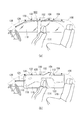
図1は、本発明の実施形態にかかるカーテンエアバッグ装置を例示した図である。図1(a)は車両室内を車幅方向の車内側から見た図であって、カーテンエアバッグ装置(以下、「エアバッグ100」と記載する。)のクッション部102の収納形態を例示している。また、図1(b)は、図1(a)のクッション部102の展開時を例示している。
FIG. 1 is a diagram illustrating a curtain airbag device according to an embodiment of the present invention. FIG. 1A is a view of the interior of a vehicle as viewed from the vehicle inner side in the vehicle width direction, and illustrates a storage form of a
図1(a)に例示するクッション部102は、緊急時に膨張展開して乗員を保護する部位である。このクッション部102は、巻回されて車両前後に長尺なロール状の収納形態となって、車両室内の側壁の上部(ルーフサイドレール104)に取り付けられ、設置される。通常、ルーフサイドレール104はその上をルーフトリム(図示省略)が覆うため、収納されたクッション部102は車両室内からは視認不能である。
The
エアバッグ100はガス発生装置であるインフレータ106を備えている。クッション部102は、インフレータ106から供給されるガスの圧力により膨張して乗員を拘束する。本実施形態で採用しているインフレータ106は、シリンダ型(筒型)のものである。現在普及しているインフレータには、ガス発生剤が充填されていてこれを燃焼させてガスを発生させるタイプや、圧縮ガスが充填されていて熱を発生させることなくガスを供給するタイプ、さらにはガス発生剤と圧縮ガスとを両方備えたタイプのものなどがある。インフレータ106としては、いずれのタイプも利用可能である。
The
図1(a)の状態において、車両108に側面衝突時やロールオーバ(横転)等が発生すると、まず車両108に備えられたセンサ(図示省略)が衝撃を感知し、これに起因してインフレータ106へ信号が発信される。この信号を受けることでインフレータ106は作動し、ガスをクッション部102へ供給する。クッション部102は、インフレータ106からのガスを受給すると、図1(b)に例示するように、車室の側壁(図1(a)のサイドウィンドウ110等)に沿うように下方へ向かって膨張展開し、乗員の保護を行う。
In the state of FIG. 1 (a), when a side collision or rollover (rollover) occurs in the
図2は、図1(b)のクッション部102の非膨張時における展開状態を例示した図である。本実施形態では、クッション部102は表面を構成する2枚の基布を重ねて縫製したり接着したりすることで形成されている。また他の例として、クッション部はOPW(One-Piece Woven)を用いての紡織によっても形成可能である。これらの手法によって、クッション部102は袋状に形成される。
FIG. 2 is a diagram illustrating an expanded state when the
インフレータ106(図1(b)参照)が作動すると、ガスは、まずクッション部102の上部のダクト部112へと流れる。ダクト部112は、車両前後方向に延びていて、ガスをクッション部102内の車両前後方向の各膨張領域へ効率よく分配する働きをする。
When the inflator 106 (see FIG. 1B) is activated, the gas first flows into the
クッション部102の膨張領域は、乗員が接触し得る位置などを考慮して、複数の小部屋(チャンバ)に区画されている。例えば、車両前側には、前部座席114(図1(b)参照)の乗員を受け止めることを目的としてチャンバ116およびチャンバ118が設けられている。また、車両後側には、後部座席120の乗員を受け止めることを目的としてチャンバ122が設けられている。
The inflating region of the
クッション部102の前端には、帯形状のストラップ124が設けられている。ストラップ124は、クッション部102とフロントピラー126(図1(b)等参照)とをつなぐ部材であって、クッション部102の膨張展開時の揺動を抑えて展開挙動を安定させ、加えてクッション部102に車両前後方向への張力を与える働きを有している。
A belt-shaped
クッション部102の上縁128に沿っては、車両108(図1(b)等参照)への取付部位として、帯状のタブ130および金属製のブラケット132が複数設けられている。以下、図3を参照して、このタブ130およびブラケット132を中心とした構成について説明する。
Along the
図3は、図2のブラケット132付近の拡大図である。図3(a)に例示するブラケット132は、ボルト等でルーフサイドレール104(図1(b)等参照)に固定される部位であって、クッション部102のタブ130に通されている。タブ130は、ブラケット132の挿通孔134に通したうえで、クッション部102の上部に縫製ラインL1等で接合される。車両取付後のクッション部102は、図1(a)のように、タブ130によってブラケット132に吊り下げた状態となる。
FIG. 3 is an enlarged view of the vicinity of the
図3(b)は、図3(b)の分解図である。ブラケット132は、板状の金属に曲げ加工等を施すことで形成されている。ブラケット132にはボルト孔136が設けられていて、このボルト孔136にボルト(図示省略)を通してルーフサイドレール104(図1(a)参照)に締結される。ボルト孔136の両脇側の端には、ルーフサイドレール104側(図中奥側)に向かってL字に延びたフック部138a、138bがそれぞれ設けられている。フック部138a、138bは、ブラケット132をルーフサイドレール104に位置決めするための部位であり、ルーフサイドレール104に設けられた所定の孔に差し込まれる。
FIG. 3B is an exploded view of FIG. The
ブラケット132の下部には、前述の挿通孔134が設けられている。挿通孔134は、車両前後方向に長径R1(図3(a)参照)を有する横長の形状をしていて、タブ130が通される。なお、本実施形態における挿通孔134は細長い楕円に近い形状であるが、挿通孔134の形状はこれに限定されない。例えば、タブ130から荷重が加えられた際の応力集中を避けるよう、長手方向の両端を上方へ湾曲させた形状なども採用可能である。
The
タブ130は、クッション部102と同様の素材で構成されていて、ブラケット132の挿通孔134に通された後、その長手方向の両端を纏めて、図3(a)のようにクッション部102の上部に縫い付けられる。タブ130は、その幅が挿通孔134よりも広く、挿通孔134に通す際には所定の領域が幅方向に折り曲げられる。
The
図4は、図3(b)のタブ130をブラケット132の挿通孔134に通す過程を例示した図である。本実施形態では、タブ130を挿通孔134に通す際に、タブ130の耐久性が向上するよう、工夫を施している。
FIG. 4 is a view illustrating a process of passing the
図4(a)に例示するように、タブ130は、布材をタブ130の幅方向に巻き重ねることで、ある程度の厚みを持たせて帯状に形成されている。このタブ130には、図4(b)に例示するように、折返し部140a、140bを設ける。折返し部140a、140bは、タブ130の幅方向の両側の側縁142a、142bをブラケット132の挿通孔134の下縁144側(図4(c)参照)に折り返すことで設けられていて、本実施形態では図4(a)に例示するタブ130の幅方向内側に頂点P1、P2を有する三角形状の領域E1、E2を折り返すことでそれぞれ設けられる。このようにして折返し部140a、140bを形成したタブ130は、図4(c)に例示するように、その折返し部140a、140bを挿通孔134の下縁144に重ねるようにして、挿通孔134に通す。
As illustrated in FIG. 4A, the
このようにして、本実施形態では図4(d)のように、タブ130のうち、ブラケット132の挿通孔134の下縁144に接するために荷重がかかりやすい部位は、折返し部E1、E2が設けられて厚みが増している。これによってタブ130は、クッション部102から荷重がかかって挿通孔134の下縁144との間で大きく擦れても、損傷することを防止できる。
As described above, in this embodiment, as shown in FIG. 4D, the folded portions E1 and E2 are portions of the
なお、図5は図4(b)の折返し部140a、140bの変形例であるが、図5に例示するように、タブ130には、折返し部140a、140bを保持する縫製ラインL2を設けてもよい。この縫製ラインL2で折返し部140a、140bの形成を保持することで、タブ130は挿通孔134へ通しやすくなり、作業性が向上する。
5 is a modified example of the folded
(タブの第1変形例)
図6は、図4のタブの第1変形例を例示した図である。図6に例示するタブ200は、折返し部202a、202bの構成において、図4のタブ130と異なっている。なお、以降に説明する各変形例において、既に説明した構成要素と同一のものに対しては、同一の符号を付することによってその説明を省略する。
(First variation of tab)
FIG. 6 is a diagram illustrating a first modification of the tab of FIG. The
図6(a)に例示するように、本例では、タブ200は、布材をタブ200の長手方向に巻き重ねることで帯状に形成されている。タブ200には、幅方向両側の側縁204a、204bにそれぞれ2つずつ、計4つの横スリット206a〜206dが設けられている。これら横スリット206a〜206dは、タブ200のうち挿通孔134(図6(c)参照)付近において、幅方向両側の側縁204a、204bから幅方向内側へ向かって切り込みを入れることで形成されている。
As illustrated in FIG. 6A, in this example, the
図6(b)に例示するように、折返し部202a、202bは、それぞれ2つの横スリットに区画されたことで、四角形状に折り返すことが可能になっている。また、このときの折り返しがよりスムーズに行えるよう、図6(a)に例示するように、折返し部202a、202bの折り目となる箇所には、その所定範囲にわたって切り込みをいれて縦スリット208a、208bを設けている。この縦スリット208a、208bを設けることによって、折返し部202a、202bは簡単に形成できるようになっている。
As illustrated in FIG. 6B, the folded
そして、図6(c)に例示するように、折返し部202a、202bもまた挿通孔134の下縁144側に折り返されていて、この下縁144に重ねられる。このようにして、本例においても図6(d)のように、タブ200のうち荷重がかかりやすい部位に折返し部202a、202bが設けられ、タブ200は挿通孔134の下縁144との間の擦れが大きくなっても損傷を防ぐことが可能になっている。
As illustrated in FIG. 6C, the folded
(タブの第2変形例)
図7は、図4のタブ130の第2変形例を例示した図である。図7に例示するタブ300もまた、折返し部302a、302bの構成において、図4のタブ130と異なっている。
(Second modification of tab)
FIG. 7 is a diagram illustrating a second modification of the
図7(a)に例示するように、タブ300にも両側の側縁304a、304bにそれぞれ2つずつ、計4つの横スリット306a〜306dが設けられている。これら横スリット306a〜306dは、例えば片側の側縁304aにおける横スリット306a、306bのように、側縁304aから幅方向内側へ向かって互いの間隔が次第に広がるよう設けられている。そのため、折返し部302a、302bは、図7(b)に例示するように、根元側が広い台形形状に形成される。そして、図7(c)のように折返し部302a、302b上にブラケット132が位置するようタブ300を挿通孔134(図7(d)参照)に通し、これによって図7(d)に例示するように挿通孔134の下縁144に折返し部302a、302bが重ねられる。
As illustrated in FIG. 7A, the
このように本例では、例えば図7(c)に例示するように、折返し部302a、302bは台形形状であってその根元側の範囲が広くなっている。したがって、タブ300に対してブラケット132が少々移動しても、折返し部302a、302bはその範囲が広いために挿通孔134上から外れることがなく、好適である。
Thus, in this example, as illustrated in FIG. 7C, for example, the folded
(タブの第3変形例)
図8は、図4のタブ130の第3変形例を例示した図である。図8(a)に例示するように、タブ400の横スリット406a〜406dもまた、例えば片側の側縁404aにおける横スリット406a、406bのように、側縁404aから幅方向内側へ向かって互いの間隔が次第に狭まるよう設けられている。そのため、折返し部402a、402bは、図8(b)に例示するように、先端側が広い台形形状に形成される。そして、図8(c)のように折返し部402a、402b上にブラケット132が位置するようタブ400を挿通孔134(図8(d)参照)に通し、図8(d)のように挿通孔134の下縁144に折返し部402a、402bが重ねられる。
(Third modification of tab)
FIG. 8 is a diagram illustrating a third modification of the
本例では、例えば図8(c)に例示するように、折返し部402a、402bは台形形状であってその先端側の範囲が広くなっている。したがって、図7(c)のタブ300と同様に、図8(c)のタブ400に対してブラケット132が少々移動しても、折返し部402a、402bはその範囲が広いために挿通孔134上から外れることがない。
In this example, as illustrated in FIG. 8C, for example, the folded-
(タブの変形例4)
図9は、図4のタブ130の第4変形例を例示した図である。図9(a)に例示するように、タブ500の両側の側縁504a、504bから内側へ向かって設けられた横スリット506a〜506dは、例えば横スリット506a、506cのように対向するもの同士が、互いの間の領域W1が挿通孔134の長径R1よりも広くなるよう離間して設けられている。このとき、タブ500はその幅自体が挿通孔134の長径R1よりも広いため、図9(b)に例示するように、タブ500を挿通孔134に通す際は側縁504a、504bの全域にわたって折り曲げて挿入することになる。
(Tab variant 4)
FIG. 9 is a diagram illustrating a fourth modification of the
本例では、タブ500が挿通孔134に通せる程にまで側縁504a、504bを折り曲げると、この折り曲げられた範囲には横スリット506a〜506dの全域も含まれることになる。この構成であると、タブ500を挿通孔134に通す際に折り曲げることで、折返し部502a、502dも同時に形成することができる。そしてこの折り曲げたタブ500を挿通孔134に通すことで、図9(c)に例示するように折返し部502a、502bを挿通孔134の下縁144上に位置させる。これによって図9(d)に例示するように、挿通孔134の下縁144に折返し部502a、502bが重ねられる。このように、本例であれば、折返し部502a、502bの形成や下縁144上への設置等の一連の作業が簡単にできる。
In this example, when the side edges 504a and 504b are bent to such an extent that the
以上、添付図面を参照しながら本発明の好適な実施形態について説明したが、以上に述べた実施形態は、本発明の好ましい例であって、これ以外の実施態様も、各種の方法で実施または遂行できる。特に本願明細書中に限定される主旨の記載がない限り、この発明は、添付図面に示した詳細な部品の形状、大きさ、および構成配置等に制約されるものではない。また、本願明細書の中に用いられた表現および用語は、説明を目的としたもので、特に限定される主旨の記載がない限り、それに限定されるものではない。 The preferred embodiments of the present invention have been described above with reference to the accompanying drawings. However, the embodiments described above are preferred examples of the present invention, and other embodiments can be implemented or performed in various ways. Can be carried out. The invention is not limited to the detailed shape, size, configuration, and the like of the components shown in the accompanying drawings unless otherwise specified in the present specification. In addition, expressions and terms used in the present specification are for the purpose of explanation, and are not limited thereto unless otherwise specified.
したがって、当業者であれば、特許請求の範囲に記載された範疇内において、各種の変更例または修正例に想到し得ることは明らかであり、それらについても当然に本発明の技術的範囲に属するものと了解される。 Therefore, it is obvious for those skilled in the art that various changes and modifications can be conceived within the scope of the claims, and these naturally belong to the technical scope of the present invention. It is understood.
また、上記実施形態においては本発明にかかるエアバッグ100を自動車に適用した場合を想定して説明したが、自動車以外にも航空機や船舶などに適用することも可能であり、同様の作用効果を得ることができる。
Moreover, in the said embodiment, although demonstrated supposing the case where the
本発明は、車両の側面衝突時やロールオーバ(横転)時に、乗員保護を目的として車両室内の側面部に沿うように膨張展開するクッション部を備えたカーテンエアバッグ装置に利用することができる。 INDUSTRIAL APPLICABILITY The present invention can be used for a curtain airbag device provided with a cushion portion that inflates and deploys along a side portion in a vehicle interior for the purpose of protecting an occupant at the time of a side collision or rollover (rollover) of a vehicle.
100 …エアバッグ、102 …クッション部、104 …ルーフサイドレール、106 …インフレータ、108 …車両、110 …サイドウィンドウ、112 …ダクト部、114 …前部座席、116、118 …前部座席付近のチャンバ、120 …後部座席、122 …後部座席付近のチャンバ、124 …ストラップ、126 …フロントピラー、128 …クッション部の上縁、130 …タブ、132 …ブラケット、134 …挿通孔、136 …ボルト孔、138a、138b …フック部、140a、140b …折返し部、142a、142b …タブの側縁、144 …挿通孔の下縁、R1 …挿通孔の長径、L1 …タブを接合する縫製ライン、P1、P2 …三角形状の領域の頂点、E1、E2 …三角形状の領域、L2 …折返し部を保持する縫製ライン、200 …第1変形例のタブ、202a、202b …折返し部、204a、204b …タブの側縁、206a、206b、206c、206d …横スリット、208a、208b …縦スリット、300 …第2変形例のタブ、302a、302b …折返し部、304a、304b …タブの側縁、306a、306b、306c、306d …横スリット、400 …第3変形例のタブ、402a、402b …折返し部、404a、404b …側縁、406a、406b、406c、406d …横スリット、500 …第4変形例のタブ、502a、502b …折返し部、504a、504b …タブの側縁、506a、506b、506c、506d …横スリット、W1 …対向する横スリット同士の間の領域
DESCRIPTION OF
Claims (6)
前記車室側壁に沿って膨張展開可能なクッション部と、
帯状であって前記複数のブラケットの挿通孔それぞれに通されて該ブラケットに前記クッション部を吊り下げる複数のタブと、
を備え、
前記タブは、
幅方向両側の側縁から幅方向内側へ向かって1つの側縁につき少なくとも2つ切り込まれた横スリットと、
前記幅方向両側の側縁のうち前記2つの横スリットに区画されて折り返し可能となってそれぞれ該挿通孔の下縁側へ折り返された折返し部と、
を有することを特徴とするカーテンエアバッグ装置。 A plurality of brackets that are attached to the upper part of the side wall of the passenger compartment along the vehicle front-rear direction, each having an insertion hole having a long diameter in the vehicle front-rear direction,
A cushion portion that can be inflated and deployed along the side wall of the passenger compartment;
A plurality of tabs that are band-shaped and are respectively passed through the insertion holes of the plurality of brackets and suspend the cushion portion on the brackets;
With
The tab is
Lateral slits cut at least two per side edge from the side edges on both sides in the width direction;
Folded portions that are divided into the two lateral slits of the side edges on both sides in the width direction and can be folded back and folded back to the lower edge side of the insertion hole,
A curtain airbag device comprising:
前記タブの幅方向両側の側縁からそれぞれ幅方向内側へ向かって設けられる対向する横スリットは、少なくとも前記挿通孔の長径よりも広く離間して設けられ、
前記折返し部は、前記タブの側縁の全体ごと折り返して設けられることを特徴とする請求項1から4のいずれか1項に記載のカーテンエアバッグ装置。 The tab is wider in width than the long diameter of the insertion hole,
Opposing lateral slits provided from the side edges on both sides in the width direction of the tab toward the inner side in the width direction are provided at least widely apart from the long diameter of the insertion hole,
The curtain airbag device according to any one of claims 1 to 4 , wherein the folded portion is provided by folding the entire side edge of the tab.
Priority Applications (1)
| Application Number | Priority Date | Filing Date | Title |
|---|---|---|---|
| JP2013059998A JP5922052B2 (en) | 2013-03-22 | 2013-03-22 | Curtain airbag device |
Applications Claiming Priority (1)
| Application Number | Priority Date | Filing Date | Title |
|---|---|---|---|
| JP2013059998A JP5922052B2 (en) | 2013-03-22 | 2013-03-22 | Curtain airbag device |
Publications (2)
| Publication Number | Publication Date |
|---|---|
| JP2014184792A JP2014184792A (en) | 2014-10-02 |
| JP5922052B2 true JP5922052B2 (en) | 2016-05-24 |
Family
ID=51832775
Family Applications (1)
| Application Number | Title | Priority Date | Filing Date |
|---|---|---|---|
| JP2013059998A Active JP5922052B2 (en) | 2013-03-22 | 2013-03-22 | Curtain airbag device |
Country Status (1)
| Country | Link |
|---|---|
| JP (1) | JP5922052B2 (en) |
Families Citing this family (7)
| Publication number | Priority date | Publication date | Assignee | Title |
|---|---|---|---|---|
| CN106143389B (en) * | 2015-04-07 | 2020-10-27 | 福特环球技术公司 | Airbag connection and vehicle airbag system comprising said airbag connection |
| US10144385B2 (en) * | 2016-12-19 | 2018-12-04 | Ford Global Technologies, Llc | Side curtain including a strip connected to an inboard panel |
| US10647285B2 (en) * | 2018-02-06 | 2020-05-12 | Autoliv Asp, Inc. | Mounting tab assemblies for securing an airbag to a vehicle |
| US11130464B2 (en) | 2018-02-06 | 2021-09-28 | Autoliv Asp, Inc. | Mounting tab assemblies for securing an airbag to a vehicle |
| CN112172732B (en) * | 2019-07-01 | 2023-07-14 | 奥托立夫开发公司 | Airbag module |
| WO2021076406A1 (en) * | 2019-10-18 | 2021-04-22 | Autoliv Asp, Inc. | Mounting tab assemblies for securing an airbag to a vehicle |
| CN212604972U (en) | 2020-06-19 | 2021-02-26 | 奥托立夫开发公司 | Lifting lug for safety air bag and safety air bag |
Family Cites Families (7)
| Publication number | Priority date | Publication date | Assignee | Title |
|---|---|---|---|---|
| JPS5248269U (en) * | 1975-10-01 | 1977-04-06 | ||
| JPS5544859Y2 (en) * | 1976-10-20 | 1980-10-21 | ||
| JPS597349Y2 (en) * | 1980-09-26 | 1984-03-06 | 株式会社椿本チエイン | fiber sling |
| US6149215A (en) * | 1998-07-07 | 2000-11-21 | Dp Brown Of Detroit Incorporated | Durable slings for vehicle frame turnover machines and method of making the slings |
| GB2356392B (en) * | 1999-11-22 | 2001-12-12 | Breed Automotive Tech | Apparatus and method for feeding seat belt webbing through an opening in a sill end bracket. |
| US7823914B2 (en) * | 2007-05-14 | 2010-11-02 | Autoliv Asp, Inc. | Airbag mounting assembly and method of manufacture |
| JP4852510B2 (en) * | 2007-10-04 | 2012-01-11 | 本田技研工業株式会社 | Airbag mounting bracket |
-
2013
- 2013-03-22 JP JP2013059998A patent/JP5922052B2/en active Active
Also Published As
| Publication number | Publication date |
|---|---|
| JP2014184792A (en) | 2014-10-02 |
Similar Documents
| Publication | Publication Date | Title |
|---|---|---|
| JP5922052B2 (en) | Curtain airbag device | |
| JP5922250B2 (en) | Curtain airbag device | |
| JP5595154B2 (en) | Curtain airbag | |
| JP6214787B2 (en) | Curtain airbag device | |
| JP5401288B2 (en) | Curtain airbag device | |
| JP5969792B2 (en) | Assembling the head protection airbag | |
| JP5826093B2 (en) | Head protection airbag device | |
| JP5746666B2 (en) | Curtain airbag for vehicle and mounting structure thereof | |
| JP2018176863A (en) | Curtain airbag device | |
| JP5478219B2 (en) | Airbag | |
| JP5968292B2 (en) | Gas guide and airbag device for vehicle airbag | |
| JP2019043197A (en) | Airbag | |
| JP5972856B2 (en) | Curtain airbag device | |
| JP2016124497A (en) | Air bag | |
| JP5998097B2 (en) | Curtain airbag | |
| JP2014180925A (en) | Curtain airbag | |
| JP7368210B2 (en) | Airbag and its folding method | |
| JP6129761B2 (en) | Gas guide and airbag device for vehicle airbag | |
| JP5947760B2 (en) | Curtain airbag device | |
| JP6768079B2 (en) | Curtain airbag device | |
| JP6111054B2 (en) | Curtain airbag device | |
| JP6580480B2 (en) | Curtain airbag device | |
| JP6379444B2 (en) | Airbag device | |
| JP2016052824A (en) | Fitting structure for curtain airbag device and curtain airbag device | |
| JP5537624B2 (en) | Airbag device |
Legal Events
| Date | Code | Title | Description |
|---|---|---|---|
| A621 | Written request for application examination |
Free format text: JAPANESE INTERMEDIATE CODE: A621 Effective date: 20141002 |
|
| A977 | Report on retrieval |
Free format text: JAPANESE INTERMEDIATE CODE: A971007 Effective date: 20151015 |
|
| A131 | Notification of reasons for refusal |
Free format text: JAPANESE INTERMEDIATE CODE: A131 Effective date: 20151110 |
|
| A521 | Request for written amendment filed |
Free format text: JAPANESE INTERMEDIATE CODE: A523 Effective date: 20151216 |
|
| A131 | Notification of reasons for refusal |
Free format text: JAPANESE INTERMEDIATE CODE: A131 Effective date: 20160126 |
|
| A521 | Request for written amendment filed |
Free format text: JAPANESE INTERMEDIATE CODE: A523 Effective date: 20160226 |
|
| TRDD | Decision of grant or rejection written | ||
| A01 | Written decision to grant a patent or to grant a registration (utility model) |
Free format text: JAPANESE INTERMEDIATE CODE: A01 Effective date: 20160405 |
|
| A61 | First payment of annual fees (during grant procedure) |
Free format text: JAPANESE INTERMEDIATE CODE: A61 Effective date: 20160413 |
|
| R150 | Certificate of patent or registration of utility model |
Ref document number: 5922052 Country of ref document: JP Free format text: JAPANESE INTERMEDIATE CODE: R150 |
|
| R250 | Receipt of annual fees |
Free format text: JAPANESE INTERMEDIATE CODE: R250 |
|
| R250 | Receipt of annual fees |
Free format text: JAPANESE INTERMEDIATE CODE: R250 |
|
| R250 | Receipt of annual fees |
Free format text: JAPANESE INTERMEDIATE CODE: R250 |
|
| R250 | Receipt of annual fees |
Free format text: JAPANESE INTERMEDIATE CODE: R250 |
|
| R250 | Receipt of annual fees |
Free format text: JAPANESE INTERMEDIATE CODE: R250 |
|
| R250 | Receipt of annual fees |
Free format text: JAPANESE INTERMEDIATE CODE: R250 |