JP5920895B2 - Method and device for isolating cells from heterogeneous solutions using microfluidic capture vortices - Google Patents
Method and device for isolating cells from heterogeneous solutions using microfluidic capture vortices Download PDFInfo
- Publication number
- JP5920895B2 JP5920895B2 JP2013528369A JP2013528369A JP5920895B2 JP 5920895 B2 JP5920895 B2 JP 5920895B2 JP 2013528369 A JP2013528369 A JP 2013528369A JP 2013528369 A JP2013528369 A JP 2013528369A JP 5920895 B2 JP5920895 B2 JP 5920895B2
- Authority
- JP
- Japan
- Prior art keywords
- cells
- microfluidic
- microfluidic channel
- vortex
- solution
- Prior art date
- Legal status (The legal status is an assumption and is not a legal conclusion. Google has not performed a legal analysis and makes no representation as to the accuracy of the status listed.)
- Active
Links
- 238000000034 method Methods 0.000 title claims description 42
- 206010028980 Neoplasm Diseases 0.000 claims description 30
- 239000012530 fluid Substances 0.000 claims description 30
- 210000004369 blood Anatomy 0.000 claims description 28
- 239000008280 blood Substances 0.000 claims description 28
- 201000011510 cancer Diseases 0.000 claims description 28
- 230000000630 rising effect Effects 0.000 claims description 10
- 230000004044 response Effects 0.000 claims description 6
- 239000003795 chemical substances by application Substances 0.000 claims description 4
- 238000004140 cleaning Methods 0.000 claims description 3
- 239000000834 fixative Substances 0.000 claims description 3
- 239000003330 peritoneal dialysis fluid Substances 0.000 claims description 2
- 210000004910 pleural fluid Anatomy 0.000 claims description 2
- 210000002700 urine Anatomy 0.000 claims description 2
- 230000007423 decrease Effects 0.000 claims 2
- 210000004027 cell Anatomy 0.000 description 203
- 239000000243 solution Substances 0.000 description 53
- 239000002245 particle Substances 0.000 description 22
- 239000000523 sample Substances 0.000 description 22
- 208000005443 Circulating Neoplastic Cells Diseases 0.000 description 17
- LOKCTEFSRHRXRJ-UHFFFAOYSA-I dipotassium trisodium dihydrogen phosphate hydrogen phosphate dichloride Chemical compound P(=O)(O)(O)[O-].[K+].P(=O)(O)([O-])[O-].[Na+].[Na+].[Cl-].[K+].[Cl-].[Na+] LOKCTEFSRHRXRJ-UHFFFAOYSA-I 0.000 description 14
- 239000002953 phosphate buffered saline Substances 0.000 description 14
- 238000002372 labelling Methods 0.000 description 13
- 210000000601 blood cell Anatomy 0.000 description 12
- 238000010586 diagram Methods 0.000 description 12
- 238000005406 washing Methods 0.000 description 9
- 239000003153 chemical reaction reagent Substances 0.000 description 8
- 239000004205 dimethyl polysiloxane Substances 0.000 description 8
- 210000003743 erythrocyte Anatomy 0.000 description 8
- 238000001914 filtration Methods 0.000 description 8
- 239000004005 microsphere Substances 0.000 description 8
- 229920000435 poly(dimethylsiloxane) Polymers 0.000 description 8
- 238000002360 preparation method Methods 0.000 description 8
- 108010090804 Streptavidin Proteins 0.000 description 7
- 238000004458 analytical method Methods 0.000 description 7
- 239000012141 concentrate Substances 0.000 description 7
- 238000000926 separation method Methods 0.000 description 7
- 238000011144 upstream manufacturing Methods 0.000 description 6
- FWBHETKCLVMNFS-UHFFFAOYSA-N 4',6-Diamino-2-phenylindol Chemical compound C1=CC(C(=N)N)=CC=C1C1=CC2=CC=C(C(N)=N)C=C2N1 FWBHETKCLVMNFS-UHFFFAOYSA-N 0.000 description 5
- 238000003556 assay Methods 0.000 description 5
- 238000005119 centrifugation Methods 0.000 description 5
- 239000011325 microbead Substances 0.000 description 5
- 239000000758 substrate Substances 0.000 description 5
- 238000013459 approach Methods 0.000 description 4
- 239000007788 liquid Substances 0.000 description 4
- 239000002609 medium Substances 0.000 description 4
- 206010006187 Breast cancer Diseases 0.000 description 3
- 208000026310 Breast neoplasm Diseases 0.000 description 3
- 229930040373 Paraformaldehyde Natural products 0.000 description 3
- 239000011324 bead Substances 0.000 description 3
- 238000012512 characterization method Methods 0.000 description 3
- 238000001514 detection method Methods 0.000 description 3
- 230000000694 effects Effects 0.000 description 3
- 239000007850 fluorescent dye Substances 0.000 description 3
- 239000011521 glass Substances 0.000 description 3
- 238000002955 isolation Methods 0.000 description 3
- 238000001000 micrograph Methods 0.000 description 3
- 229920002866 paraformaldehyde Polymers 0.000 description 3
- 238000012545 processing Methods 0.000 description 3
- 238000011160 research Methods 0.000 description 3
- 101000738771 Homo sapiens Receptor-type tyrosine-protein phosphatase C Proteins 0.000 description 2
- 102100037422 Receptor-type tyrosine-protein phosphatase C Human genes 0.000 description 2
- XUIMIQQOPSSXEZ-UHFFFAOYSA-N Silicon Chemical compound [Si] XUIMIQQOPSSXEZ-UHFFFAOYSA-N 0.000 description 2
- 230000008901 benefit Effects 0.000 description 2
- 230000015572 biosynthetic process Effects 0.000 description 2
- 238000011109 contamination Methods 0.000 description 2
- 230000008602 contraction Effects 0.000 description 2
- 238000002474 experimental method Methods 0.000 description 2
- 230000001605 fetal effect Effects 0.000 description 2
- 239000000463 material Substances 0.000 description 2
- 230000008569 process Effects 0.000 description 2
- 229910052710 silicon Inorganic materials 0.000 description 2
- 239000010703 silicon Substances 0.000 description 2
- UCSJYZPVAKXKNQ-HZYVHMACSA-N streptomycin Chemical compound CN[C@H]1[C@H](O)[C@@H](O)[C@H](CO)O[C@H]1O[C@@H]1[C@](C=O)(O)[C@H](C)O[C@H]1O[C@@H]1[C@@H](NC(N)=N)[C@H](O)[C@@H](NC(N)=N)[C@H](O)[C@H]1O UCSJYZPVAKXKNQ-HZYVHMACSA-N 0.000 description 2
- 230000004083 survival effect Effects 0.000 description 2
- 101001011741 Bos taurus Insulin Proteins 0.000 description 1
- 238000000018 DNA microarray Methods 0.000 description 1
- 239000006144 Dulbecco’s modified Eagle's medium Substances 0.000 description 1
- 102000018651 Epithelial Cell Adhesion Molecule Human genes 0.000 description 1
- 108010066687 Epithelial Cell Adhesion Molecule Proteins 0.000 description 1
- 102000011782 Keratins Human genes 0.000 description 1
- 108010076876 Keratins Proteins 0.000 description 1
- 229930182555 Penicillin Natural products 0.000 description 1
- JGSARLDLIJGVTE-MBNYWOFBSA-N Penicillin G Chemical compound N([C@H]1[C@H]2SC([C@@H](N2C1=O)C(O)=O)(C)C)C(=O)CC1=CC=CC=C1 JGSARLDLIJGVTE-MBNYWOFBSA-N 0.000 description 1
- 239000004793 Polystyrene Substances 0.000 description 1
- 201000001718 Roberts syndrome Diseases 0.000 description 1
- 208000012474 Roberts-SC phocomelia syndrome Diseases 0.000 description 1
- 239000000980 acid dye Substances 0.000 description 1
- 230000002776 aggregation Effects 0.000 description 1
- 238000004220 aggregation Methods 0.000 description 1
- 210000001124 body fluid Anatomy 0.000 description 1
- 239000010839 body fluid Substances 0.000 description 1
- IXIBAKNTJSCKJM-BUBXBXGNSA-N bovine insulin Chemical compound C([C@@H](C(=O)N[C@@H](CC(C)C)C(=O)N[C@H]1CSSC[C@H]2C(=O)N[C@@H](C)C(=O)N[C@@H](CO)C(=O)N[C@H](C(=O)N[C@H](C(N[C@@H](CO)C(=O)N[C@@H](CC(C)C)C(=O)N[C@@H](CC=3C=CC(O)=CC=3)C(=O)N[C@@H](CCC(N)=O)C(=O)N[C@@H](CC(C)C)C(=O)N[C@@H](CCC(O)=O)C(=O)N[C@@H](CC(N)=O)C(=O)N[C@@H](CC=3C=CC(O)=CC=3)C(=O)N[C@@H](CSSC[C@H](NC(=O)[C@H](C(C)C)NC(=O)[C@H](CC(C)C)NC(=O)[C@H](CC=3C=CC(O)=CC=3)NC(=O)[C@H](CC(C)C)NC(=O)[C@H](C)NC(=O)[C@H](CCC(O)=O)NC(=O)[C@H](C(C)C)NC(=O)[C@H](CC(C)C)NC(=O)[C@H](CC=3NC=NC=3)NC(=O)[C@H](CO)NC(=O)CNC1=O)C(=O)NCC(=O)N[C@@H](CCC(O)=O)C(=O)N[C@@H](CCCNC(N)=N)C(=O)NCC(=O)N[C@@H](CC=1C=CC=CC=1)C(=O)N[C@@H](CC=1C=CC=CC=1)C(=O)N[C@@H](CC=1C=CC(O)=CC=1)C(=O)N[C@@H]([C@@H](C)O)C(=O)N1[C@@H](CCC1)C(=O)N[C@@H](CCCCN)C(=O)N[C@@H](C)C(O)=O)C(=O)N[C@@H](CC(N)=O)C(O)=O)=O)CSSC[C@@H](C(N2)=O)NC(=O)[C@H](CCC(N)=O)NC(=O)[C@H](CCC(O)=O)NC(=O)[C@H](C(C)C)NC(=O)[C@@H](NC(=O)CN)[C@@H](C)CC)C(C)C)NC(=O)[C@H](CCC(N)=O)NC(=O)[C@H](CC(N)=O)NC(=O)[C@@H](NC(=O)[C@@H](N)CC=1C=CC=CC=1)C(C)C)C1=CN=CN1 IXIBAKNTJSCKJM-BUBXBXGNSA-N 0.000 description 1
- 230000008859 change Effects 0.000 description 1
- 210000003040 circulating cell Anatomy 0.000 description 1
- 238000003759 clinical diagnosis Methods 0.000 description 1
- 230000003750 conditioning effect Effects 0.000 description 1
- 230000003247 decreasing effect Effects 0.000 description 1
- 238000013461 design Methods 0.000 description 1
- 238000003745 diagnosis Methods 0.000 description 1
- 239000012470 diluted sample Substances 0.000 description 1
- 238000010790 dilution Methods 0.000 description 1
- 239000012895 dilution Substances 0.000 description 1
- 230000009977 dual effect Effects 0.000 description 1
- 238000005516 engineering process Methods 0.000 description 1
- 238000011049 filling Methods 0.000 description 1
- 239000010419 fine particle Substances 0.000 description 1
- 238000002073 fluorescence micrograph Methods 0.000 description 1
- 238000001215 fluorescent labelling Methods 0.000 description 1
- 238000013537 high throughput screening Methods 0.000 description 1
- 210000002287 horizontal cell Anatomy 0.000 description 1
- 238000012744 immunostaining Methods 0.000 description 1
- 238000011534 incubation Methods 0.000 description 1
- 238000002347 injection Methods 0.000 description 1
- 239000007924 injection Substances 0.000 description 1
- 238000009434 installation Methods 0.000 description 1
- 210000000265 leukocyte Anatomy 0.000 description 1
- 230000036210 malignancy Effects 0.000 description 1
- 238000004519 manufacturing process Methods 0.000 description 1
- 230000008774 maternal effect Effects 0.000 description 1
- 238000005459 micromachining Methods 0.000 description 1
- 239000011859 microparticle Substances 0.000 description 1
- 238000012986 modification Methods 0.000 description 1
- 230000004048 modification Effects 0.000 description 1
- 238000012544 monitoring process Methods 0.000 description 1
- 230000000877 morphologic effect Effects 0.000 description 1
- UPSFMJHZUCSEHU-JYGUBCOQSA-N n-[(2s,3r,4r,5s,6r)-2-[(2r,3s,4r,5r,6s)-5-acetamido-4-hydroxy-2-(hydroxymethyl)-6-(4-methyl-2-oxochromen-7-yl)oxyoxan-3-yl]oxy-4,5-dihydroxy-6-(hydroxymethyl)oxan-3-yl]acetamide Chemical compound CC(=O)N[C@@H]1[C@@H](O)[C@H](O)[C@@H](CO)O[C@H]1O[C@H]1[C@H](O)[C@@H](NC(C)=O)[C@H](OC=2C=C3OC(=O)C=C(C)C3=CC=2)O[C@@H]1CO UPSFMJHZUCSEHU-JYGUBCOQSA-N 0.000 description 1
- 150000007523 nucleic acids Chemical class 0.000 description 1
- 102000039446 nucleic acids Human genes 0.000 description 1
- 108020004707 nucleic acids Proteins 0.000 description 1
- 239000008188 pellet Substances 0.000 description 1
- 229940049954 penicillin Drugs 0.000 description 1
- 229920002120 photoresistant polymer Polymers 0.000 description 1
- -1 polydimethylsiloxane Polymers 0.000 description 1
- 229920002223 polystyrene Polymers 0.000 description 1
- 238000003793 prenatal diagnosis Methods 0.000 description 1
- 238000004393 prognosis Methods 0.000 description 1
- 230000003134 recirculating effect Effects 0.000 description 1
- 238000011084 recovery Methods 0.000 description 1
- 238000010992 reflux Methods 0.000 description 1
- 238000005001 rutherford backscattering spectroscopy Methods 0.000 description 1
- 238000002174 soft lithography Methods 0.000 description 1
- 238000010561 standard procedure Methods 0.000 description 1
- 229960005322 streptomycin Drugs 0.000 description 1
- 239000000126 substance Substances 0.000 description 1
- 239000006228 supernatant Substances 0.000 description 1
- 238000012546 transfer Methods 0.000 description 1
- 210000004881 tumor cell Anatomy 0.000 description 1
- 239000002699 waste material Substances 0.000 description 1
Images


Classifications
-
- C—CHEMISTRY; METALLURGY
- C12—BIOCHEMISTRY; BEER; SPIRITS; WINE; VINEGAR; MICROBIOLOGY; ENZYMOLOGY; MUTATION OR GENETIC ENGINEERING
- C12Q—MEASURING OR TESTING PROCESSES INVOLVING ENZYMES, NUCLEIC ACIDS OR MICROORGANISMS; COMPOSITIONS OR TEST PAPERS THEREFOR; PROCESSES OF PREPARING SUCH COMPOSITIONS; CONDITION-RESPONSIVE CONTROL IN MICROBIOLOGICAL OR ENZYMOLOGICAL PROCESSES
- C12Q1/00—Measuring or testing processes involving enzymes, nucleic acids or microorganisms; Compositions therefor; Processes of preparing such compositions
- C12Q1/02—Measuring or testing processes involving enzymes, nucleic acids or microorganisms; Compositions therefor; Processes of preparing such compositions involving viable microorganisms
- C12Q1/24—Methods of sampling, or inoculating or spreading a sample; Methods of physically isolating an intact microorganisms
-
- B—PERFORMING OPERATIONS; TRANSPORTING
- B01—PHYSICAL OR CHEMICAL PROCESSES OR APPARATUS IN GENERAL
- B01L—CHEMICAL OR PHYSICAL LABORATORY APPARATUS FOR GENERAL USE
- B01L3/00—Containers or dishes for laboratory use, e.g. laboratory glassware; Droppers
- B01L3/50—Containers for the purpose of retaining a material to be analysed, e.g. test tubes
- B01L3/502—Containers for the purpose of retaining a material to be analysed, e.g. test tubes with fluid transport, e.g. in multi-compartment structures
- B01L3/5027—Containers for the purpose of retaining a material to be analysed, e.g. test tubes with fluid transport, e.g. in multi-compartment structures by integrated microfluidic structures, i.e. dimensions of channels and chambers are such that surface tension forces are important, e.g. lab-on-a-chip
- B01L3/502746—Containers for the purpose of retaining a material to be analysed, e.g. test tubes with fluid transport, e.g. in multi-compartment structures by integrated microfluidic structures, i.e. dimensions of channels and chambers are such that surface tension forces are important, e.g. lab-on-a-chip characterised by the means for controlling flow resistance, e.g. flow controllers, baffles
-
- B—PERFORMING OPERATIONS; TRANSPORTING
- B01—PHYSICAL OR CHEMICAL PROCESSES OR APPARATUS IN GENERAL
- B01L—CHEMICAL OR PHYSICAL LABORATORY APPARATUS FOR GENERAL USE
- B01L3/00—Containers or dishes for laboratory use, e.g. laboratory glassware; Droppers
- B01L3/50—Containers for the purpose of retaining a material to be analysed, e.g. test tubes
- B01L3/502—Containers for the purpose of retaining a material to be analysed, e.g. test tubes with fluid transport, e.g. in multi-compartment structures
- B01L3/5027—Containers for the purpose of retaining a material to be analysed, e.g. test tubes with fluid transport, e.g. in multi-compartment structures by integrated microfluidic structures, i.e. dimensions of channels and chambers are such that surface tension forces are important, e.g. lab-on-a-chip
- B01L3/502761—Containers for the purpose of retaining a material to be analysed, e.g. test tubes with fluid transport, e.g. in multi-compartment structures by integrated microfluidic structures, i.e. dimensions of channels and chambers are such that surface tension forces are important, e.g. lab-on-a-chip specially adapted for handling suspended solids or molecules independently from the bulk fluid flow, e.g. for trapping or sorting beads, for physically stretching molecules
-
- C—CHEMISTRY; METALLURGY
- C12—BIOCHEMISTRY; BEER; SPIRITS; WINE; VINEGAR; MICROBIOLOGY; ENZYMOLOGY; MUTATION OR GENETIC ENGINEERING
- C12M—APPARATUS FOR ENZYMOLOGY OR MICROBIOLOGY; APPARATUS FOR CULTURING MICROORGANISMS FOR PRODUCING BIOMASS, FOR GROWING CELLS OR FOR OBTAINING FERMENTATION OR METABOLIC PRODUCTS, i.e. BIOREACTORS OR FERMENTERS
- C12M23/00—Constructional details, e.g. recesses, hinges
- C12M23/02—Form or structure of the vessel
- C12M23/16—Microfluidic devices; Capillary tubes
-
- C—CHEMISTRY; METALLURGY
- C12—BIOCHEMISTRY; BEER; SPIRITS; WINE; VINEGAR; MICROBIOLOGY; ENZYMOLOGY; MUTATION OR GENETIC ENGINEERING
- C12M—APPARATUS FOR ENZYMOLOGY OR MICROBIOLOGY; APPARATUS FOR CULTURING MICROORGANISMS FOR PRODUCING BIOMASS, FOR GROWING CELLS OR FOR OBTAINING FERMENTATION OR METABOLIC PRODUCTS, i.e. BIOREACTORS OR FERMENTERS
- C12M29/00—Means for introduction, extraction or recirculation of materials, e.g. pumps
-
- C—CHEMISTRY; METALLURGY
- C12—BIOCHEMISTRY; BEER; SPIRITS; WINE; VINEGAR; MICROBIOLOGY; ENZYMOLOGY; MUTATION OR GENETIC ENGINEERING
- C12M—APPARATUS FOR ENZYMOLOGY OR MICROBIOLOGY; APPARATUS FOR CULTURING MICROORGANISMS FOR PRODUCING BIOMASS, FOR GROWING CELLS OR FOR OBTAINING FERMENTATION OR METABOLIC PRODUCTS, i.e. BIOREACTORS OR FERMENTERS
- C12M47/00—Means for after-treatment of the produced biomass or of the fermentation or metabolic products, e.g. storage of biomass
- C12M47/04—Cell isolation or sorting
-
- C—CHEMISTRY; METALLURGY
- C12—BIOCHEMISTRY; BEER; SPIRITS; WINE; VINEGAR; MICROBIOLOGY; ENZYMOLOGY; MUTATION OR GENETIC ENGINEERING
- C12Q—MEASURING OR TESTING PROCESSES INVOLVING ENZYMES, NUCLEIC ACIDS OR MICROORGANISMS; COMPOSITIONS OR TEST PAPERS THEREFOR; PROCESSES OF PREPARING SUCH COMPOSITIONS; CONDITION-RESPONSIVE CONTROL IN MICROBIOLOGICAL OR ENZYMOLOGICAL PROCESSES
- C12Q1/00—Measuring or testing processes involving enzymes, nucleic acids or microorganisms; Compositions therefor; Processes of preparing such compositions
- C12Q1/68—Measuring or testing processes involving enzymes, nucleic acids or microorganisms; Compositions therefor; Processes of preparing such compositions involving nucleic acids
-
- G—PHYSICS
- G01—MEASURING; TESTING
- G01N—INVESTIGATING OR ANALYSING MATERIALS BY DETERMINING THEIR CHEMICAL OR PHYSICAL PROPERTIES
- G01N1/00—Sampling; Preparing specimens for investigation
- G01N1/28—Preparing specimens for investigation including physical details of (bio-)chemical methods covered elsewhere, e.g. G01N33/50, C12Q
- G01N1/40—Concentrating samples
- G01N1/4077—Concentrating samples by other techniques involving separation of suspended solids
-
- G—PHYSICS
- G01—MEASURING; TESTING
- G01N—INVESTIGATING OR ANALYSING MATERIALS BY DETERMINING THEIR CHEMICAL OR PHYSICAL PROPERTIES
- G01N33/00—Investigating or analysing materials by specific methods not covered by groups G01N1/00 - G01N31/00
- G01N33/48—Biological material, e.g. blood, urine; Haemocytometers
- G01N33/50—Chemical analysis of biological material, e.g. blood, urine; Testing involving biospecific ligand binding methods; Immunological testing
- G01N33/5005—Chemical analysis of biological material, e.g. blood, urine; Testing involving biospecific ligand binding methods; Immunological testing involving human or animal cells
- G01N33/5091—Chemical analysis of biological material, e.g. blood, urine; Testing involving biospecific ligand binding methods; Immunological testing involving human or animal cells for testing the pathological state of an organism
-
- G—PHYSICS
- G01—MEASURING; TESTING
- G01N—INVESTIGATING OR ANALYSING MATERIALS BY DETERMINING THEIR CHEMICAL OR PHYSICAL PROPERTIES
- G01N33/00—Investigating or analysing materials by specific methods not covered by groups G01N1/00 - G01N31/00
- G01N33/48—Biological material, e.g. blood, urine; Haemocytometers
- G01N33/50—Chemical analysis of biological material, e.g. blood, urine; Testing involving biospecific ligand binding methods; Immunological testing
- G01N33/58—Chemical analysis of biological material, e.g. blood, urine; Testing involving biospecific ligand binding methods; Immunological testing involving labelled substances
- G01N33/582—Chemical analysis of biological material, e.g. blood, urine; Testing involving biospecific ligand binding methods; Immunological testing involving labelled substances with fluorescent label
-
- B—PERFORMING OPERATIONS; TRANSPORTING
- B01—PHYSICAL OR CHEMICAL PROCESSES OR APPARATUS IN GENERAL
- B01L—CHEMICAL OR PHYSICAL LABORATORY APPARATUS FOR GENERAL USE
- B01L2200/00—Solutions for specific problems relating to chemical or physical laboratory apparatus
- B01L2200/06—Fluid handling related problems
- B01L2200/0647—Handling flowable solids, e.g. microscopic beads, cells, particles
- B01L2200/0668—Trapping microscopic beads
-
- B—PERFORMING OPERATIONS; TRANSPORTING
- B01—PHYSICAL OR CHEMICAL PROCESSES OR APPARATUS IN GENERAL
- B01L—CHEMICAL OR PHYSICAL LABORATORY APPARATUS FOR GENERAL USE
- B01L2300/00—Additional constructional details
- B01L2300/08—Geometry, shape and general structure
- B01L2300/0809—Geometry, shape and general structure rectangular shaped
- B01L2300/0816—Cards, e.g. flat sample carriers usually with flow in two horizontal directions
-
- B—PERFORMING OPERATIONS; TRANSPORTING
- B01—PHYSICAL OR CHEMICAL PROCESSES OR APPARATUS IN GENERAL
- B01L—CHEMICAL OR PHYSICAL LABORATORY APPARATUS FOR GENERAL USE
- B01L2300/00—Additional constructional details
- B01L2300/08—Geometry, shape and general structure
- B01L2300/0861—Configuration of multiple channels and/or chambers in a single devices
- B01L2300/0864—Configuration of multiple channels and/or chambers in a single devices comprising only one inlet and multiple receiving wells, e.g. for separation, splitting
-
- B—PERFORMING OPERATIONS; TRANSPORTING
- B01—PHYSICAL OR CHEMICAL PROCESSES OR APPARATUS IN GENERAL
- B01L—CHEMICAL OR PHYSICAL LABORATORY APPARATUS FOR GENERAL USE
- B01L2300/00—Additional constructional details
- B01L2300/08—Geometry, shape and general structure
- B01L2300/0861—Configuration of multiple channels and/or chambers in a single devices
- B01L2300/0867—Multiple inlets and one sample wells, e.g. mixing, dilution
-
- B—PERFORMING OPERATIONS; TRANSPORTING
- B01—PHYSICAL OR CHEMICAL PROCESSES OR APPARATUS IN GENERAL
- B01L—CHEMICAL OR PHYSICAL LABORATORY APPARATUS FOR GENERAL USE
- B01L2300/00—Additional constructional details
- B01L2300/08—Geometry, shape and general structure
- B01L2300/0861—Configuration of multiple channels and/or chambers in a single devices
- B01L2300/087—Multiple sequential chambers
-
- B—PERFORMING OPERATIONS; TRANSPORTING
- B01—PHYSICAL OR CHEMICAL PROCESSES OR APPARATUS IN GENERAL
- B01L—CHEMICAL OR PHYSICAL LABORATORY APPARATUS FOR GENERAL USE
- B01L2400/00—Moving or stopping fluids
- B01L2400/04—Moving fluids with specific forces or mechanical means
- B01L2400/0475—Moving fluids with specific forces or mechanical means specific mechanical means and fluid pressure
- B01L2400/0487—Moving fluids with specific forces or mechanical means specific mechanical means and fluid pressure fluid pressure, pneumatics
-
- B—PERFORMING OPERATIONS; TRANSPORTING
- B01—PHYSICAL OR CHEMICAL PROCESSES OR APPARATUS IN GENERAL
- B01L—CHEMICAL OR PHYSICAL LABORATORY APPARATUS FOR GENERAL USE
- B01L2400/00—Moving or stopping fluids
- B01L2400/08—Regulating or influencing the flow resistance
- B01L2400/082—Active control of flow resistance, e.g. flow controllers
-
- B—PERFORMING OPERATIONS; TRANSPORTING
- B01—PHYSICAL OR CHEMICAL PROCESSES OR APPARATUS IN GENERAL
- B01L—CHEMICAL OR PHYSICAL LABORATORY APPARATUS FOR GENERAL USE
- B01L2400/00—Moving or stopping fluids
- B01L2400/08—Regulating or influencing the flow resistance
- B01L2400/084—Passive control of flow resistance
- B01L2400/086—Passive control of flow resistance using baffles or other fixed flow obstructions
-
- G—PHYSICS
- G01—MEASURING; TESTING
- G01N—INVESTIGATING OR ANALYSING MATERIALS BY DETERMINING THEIR CHEMICAL OR PHYSICAL PROPERTIES
- G01N1/00—Sampling; Preparing specimens for investigation
- G01N1/28—Preparing specimens for investigation including physical details of (bio-)chemical methods covered elsewhere, e.g. G01N33/50, C12Q
- G01N1/40—Concentrating samples
Landscapes
- Health & Medical Sciences (AREA)
- Chemical & Material Sciences (AREA)
- Life Sciences & Earth Sciences (AREA)
- Engineering & Computer Science (AREA)
- Organic Chemistry (AREA)
- General Health & Medical Sciences (AREA)
- Zoology (AREA)
- Wood Science & Technology (AREA)
- Biotechnology (AREA)
- Bioinformatics & Cheminformatics (AREA)
- Biochemistry (AREA)
- Analytical Chemistry (AREA)
- Immunology (AREA)
- Biomedical Technology (AREA)
- Molecular Biology (AREA)
- Microbiology (AREA)
- Hematology (AREA)
- Physics & Mathematics (AREA)
- General Engineering & Computer Science (AREA)
- Genetics & Genomics (AREA)
- Dispersion Chemistry (AREA)
- Clinical Laboratory Science (AREA)
- Pathology (AREA)
- Urology & Nephrology (AREA)
- Proteomics, Peptides & Aminoacids (AREA)
- Cell Biology (AREA)
- Sustainable Development (AREA)
- Chemical Kinetics & Catalysis (AREA)
- General Physics & Mathematics (AREA)
- Medicinal Chemistry (AREA)
- Food Science & Technology (AREA)
- Biophysics (AREA)
- Fluid Mechanics (AREA)
- Physiology (AREA)
- Tropical Medicine & Parasitology (AREA)
- Apparatus Associated With Microorganisms And Enzymes (AREA)
- Physical Or Chemical Processes And Apparatus (AREA)
- Micro-Organisms Or Cultivation Processes Thereof (AREA)
Description
関連出願
本出願は、2010年9月14日に出願された米国暫定特許出願第61/382,840号の優先権を主張する。優先権は35U.S.C.§119に基づく。上述の特許出願は、ここに完全に記載されているものとして引用により組み込まれている。
RELATED APPLICATION This application claims priority to US Provisional Patent Application No. 61 / 382,840, filed Sep. 14, 2010. The priority is 35U. S. C. Based on §119. The aforementioned patent applications are hereby incorporated by reference as if fully set forth herein.
技術分野
本発明が属する分野は、一般的に、細胞又は粒子の単離と選別を行うマイクロ流体デバイスおよび方法に関する。特に、本発明が属する分野は、マイクロ流体捕獲渦を使用して細胞又は粒子を不均一溶液から単離するマイクロ流体デバイスおよび方法に関する。
TECHNICAL FIELD The field to which the present invention relates generally relates to microfluidic devices and methods for isolating and sorting cells or particles. In particular, the field to which the present invention relates relates to microfluidic devices and methods for isolating cells or particles from heterogeneous solutions using microfluidic capture vortices.
標準的な卓上遠心分離機は、生命科学の研究所で細胞生物学研究と医療診断における試料調整に普遍的に使用されている最も一般的な器具の一つである。典型的な調整手順では、細胞を標識化して洗浄するのに複数回の遠心分離ステップが必要であるが、診断と研究に時間と手間とコストがかかる。実際、アッセイ自体は非常に小型化され自動化されているが、これらのアッセイに必要なサンプル調整は将来的な自動化のキーターゲットとして認識されてきた。 A standard tabletop centrifuge is one of the most common instruments used universally for sample preparation in cell biology research and medical diagnostics in life science laboratories. Typical conditioning procedures require multiple centrifugation steps to label and wash cells, but are time consuming, labor intensive and costly for diagnosis and research. In fact, the assays themselves are very small and automated, but the sample preparation required for these assays has been recognized as a key target for future automation.
遠心分離機は、遠心分離機を非常に広く使用する三つの臨界的サンプル調整ステップである、(i)サイズ/密度による細胞分離、(ii)細胞濃縮、及び(iii)溶液交換、を行う。遠心分離機はこのような全く異なる機能を実行することができるため、小型化したプラットフォームでこれらの機能を実現することは困難であった。小型化したマイクロ流体によるアプローチは、これらの機能のうち一つか二つを実装することができることがある。例えば、サイズと密度による細胞分離は、物理的な障害物、外力、あるいは流体力を用いて、異なるアウトレットにおける回収用マイクロチャネル内の規定の場所に粒子を案内することによって行うことができる。これらの方法では、高分解能の細胞分離を提供できる一方で、典型的な回収液量が注入した液量と同じである。すなわち、有意な濃度が達成されない。この出力量が大きいと、大きな視野をスキャニングして対象の細胞を観察することが必要である下流側の細胞検出プラットフォームを邪魔したり、あるいは、回収した細胞を溶解させなくてはならない場合に、対象の生物分子を希釈してしまうことがある。したがって、ある濃縮方法を分離システムとインラインで用いて迅速な検出と分析を行うためには、液量を低減する必要がある。 The centrifuge performs three critical sample preparation steps that use the centrifuge very widely: (i) cell separation by size / density, (ii) cell concentration, and (iii) solution exchange. Since centrifuges can perform such completely different functions, it has been difficult to achieve these functions on a miniaturized platform. A miniaturized microfluidic approach may be able to implement one or two of these functions. For example, cell separation by size and density can be performed by guiding particles to defined locations within collection microchannels at different outlets using physical obstacles, external forces, or fluid forces. While these methods can provide high resolution cell separation, the typical recovery volume is the same as the injected volume. That is, no significant concentration is achieved. If this output is large, it may interfere with the downstream cell detection platform that needs to scan the large field of view and observe the cells of interest, or if the recovered cells must be lysed, The target biomolecule may be diluted. Therefore, in order to perform rapid detection and analysis using a certain concentration method in-line with the separation system, it is necessary to reduce the amount of liquid.
マイクロ流体システムを用いて局所領域に粒子と細胞を濃縮させる技術には様々なものがある。これらの技術の内、機械的なトラップが最も一般的に使用されている方法である。この方法は粒子と細胞を物理的構造体に固定して、試薬を複数段階でかん流させて、溶液交換を介してオンチップで細胞アッセイを行うことができる。しかしながら、更に下流側で分析を行うために、必要に応じて粒子と細胞を放出することが重要になることがある。濃度と放出に成功しても、これらのトラップ−放出システムで固定された細胞は、トラップの中に無理に入り、より容量の大きいスループットで操作するときにダメージを受けることになり、これによって、濃縮ファクタが希少細胞濃度に、あるいは細胞溶液を希釈するのに必要なもの以下に制限される。したがって、伝統的な遠心分離器のすべての機能とフレキシビリティを概括する一般的な小型化ツールは、未だにできていない。 There are various techniques for concentrating particles and cells in a local region using a microfluidic system. Of these techniques, mechanical traps are the most commonly used method. This method can immobilize particles and cells to a physical structure, perfuse the reagents in multiple steps, and perform on-chip cell assays via solution exchange. However, it may be important to release particles and cells as needed for further downstream analysis. Despite successful concentration and release, cells fixed in these trap-release systems will be forced into the trap and will be damaged when operating at higher capacity throughput, The concentration factor is limited to the rare cell concentration or below that required to dilute the cell solution. Thus, a general miniaturization tool that outlines all the functions and flexibility of a traditional centrifuge has not yet been made.
マイクロ流体構造内での渦の形成は、集束とフィルタレーションの強化に用いられてきた。例えば、Park et al.(Jae−Sung et al.,Conituous focusing of microparticles using inertial lift force and vorticity via multi−orifice microfluidic channels,Lab Chip,9,939−948(2009))は実験に使用するマイクロ流体デバイスを開示しており、これは、一連の突然拡張及び収縮するチャネルを用いて硬い微粒子を集束させる。所定の流速で、この拡張したチャネル内に渦が形成される。この膨張したチャネル内に形成された渦が、筒状ピンチ効果のような横方向の粒子の移動を誘発する。ある長さのマイクロチャネルに沿って一連のこれらの拡張したチャネルを設けることによって、剛体マイクロ粒子が徐々にマイクロチャネルの反対側に移動する(すなわち、集束して)ことができる。しかしながら、重要なことは、拡張したチャネルが粒子をトラップしないことである。代替的に、Park et al.は、デバイスを通過する微粒子が連続的に集束する構造を開示している。Park et al.では、小径(直径7μm)のポリスチレンマイクロスフェアが、マルチオリフィスマイクロチャネルを通過したが、これらの粒子の捕獲は観察されなかった。Park et al.は、更に、大きいサイズの粒子は、渦が形成された拡張チャネル領域から離れる傾向にあることを観察した。Park et al.は、また、最大慣性揚力値とするためにはサンプル中の粒子が硬い球形でなくてはならず、これはもともと一般的に変形可能な生体細胞と共に使用することに明らかに逆行している。構造的には、Park et al.は、むしろ小さいサイズの拡張チャネルを開示しており、これは、上流側の収縮チャネルに対して約80μm外側に拡張する。更に、拡張チャネルの長さも短く、200μmであると開示されている。 Vortex formation within microfluidic structures has been used to enhance focusing and filtering. For example, Park et al. (Jae-Sung et al., Continuus focusing of microparticulates using internal lift force and vitality vitality multi-oriented microfluidics, 9 This focuses hard particles using a series of suddenly expanding and contracting channels. A vortex is formed in this expanded channel at a predetermined flow rate. The vortices formed in this expanded channel induce lateral particle movement such as a cylindrical pinch effect. By providing a series of these expanded channels along a length of microchannel, rigid microparticles can gradually move (ie, focus) to the opposite side of the microchannel. However, what is important is that the expanded channel does not trap particles. Alternatively, Park et al. Discloses a structure in which fine particles passing through a device are continuously focused. Park et al. Then, small diameter (7 μm diameter) polystyrene microspheres passed through multi-orifice microchannels, but no capture of these particles was observed. Park et al. Further observed that larger sized particles tend to move away from the expanded channel region where vortices are formed. Park et al. Also, in order to achieve maximum inertial lift values, the particles in the sample must be hard spheres, which is clearly contrary to use with living cells that are generally generally deformable. Structurally, Park et al. Discloses a rather small size expansion channel, which extends about 80 μm outward relative to the upstream contraction channel. Furthermore, the length of the extension channel is also short and is disclosed as 200 μm.
米国特許出願第2008/0318324号(Chiu et al.)は、がん細胞の高スループットスクリーニング用バイオチップを開示している。このデバイスは、噴出フィルタレーションを使用して、体液サンプルから腫瘍細胞を分離するようにしている。噴出フィルタレーションとは、フローチャネル内部のフィルタレーション媒体又は形態学的特徴によって流体が分散するあるいは再分配されるフィルタレーション構造を意味する。Chiu et al.では、フィルタレーション媒体が細胞の幅より小さい幅を有する側壁開口である。一の実施例では、Chiu et al.は、流れを遅くしたり早くしたりする拡張及び収縮ポイントを有する1−Dチャネルを開示している。Chiu et al.は、高速で流体が分離し、流体フローを動的に代えることによって、フィルタレーション動作に役立つ内部微小渦を形成することを開示している。しかしながら、この微小渦は、デバイスを通過する細胞をトラップしない。むしろ、チャネル部分を埋めている開口が、サイズの大きい細胞がそこを通過しないようにすることによって、サイズの大きい細胞を保持している。集中又はフィルタレーション媒体を助ける目的で渦を生成する構造が開示されているが、これらの構造は、その中の細胞を選択的に捕獲するように使用されていない。 US Patent Application No. 2008/0318324 (Chiu et al.) Discloses a biochip for high-throughput screening of cancer cells. This device uses ejection filtration to separate tumor cells from a body fluid sample. By ejection filtration is meant a filtration structure in which fluid is dispersed or redistributed by a filtering medium or morphological features within the flow channel. Chiu et al. Then, the filtration medium is a side wall opening having a width smaller than the width of the cell. In one embodiment, Chiu et al. Discloses a 1-D channel with expansion and contraction points that slow or speed the flow. Chiu et al. Discloses the formation of internal micro-vortices that aid in filtration operations by separating fluids at high speed and dynamically changing fluid flow. However, this microvortex does not trap cells passing through the device. Rather, the opening filling the channel portion retains the large cells by preventing large cells from passing therethrough. Although structures that generate vortices for the purpose of aiding concentration or filtering media have been disclosed, these structures have not been used to selectively capture cells therein.
本発明の一実施例では、細胞を分離する方法が、インレットとアウトレットに連結された少なくとも一のマイクロ流体チャネルを有するマイクロ流体デバイスを提供するステップを具えており、少なくとも一のマイクロ流体チャネルがその長さに沿って配置した少なくとも一の拡張領域を具え、この少なくとも一の拡張領域が、流体の流れに応じて少なくとも一の拡張領域内で渦を生成するように構成された少なくとも一のマイクロ流体チャネルの断面寸法の急激な増大を含む。細胞集団を含む溶液をインレットに流す。少なくともいくつかの細胞が、少なくとも一の拡張領域内にできた渦内にトラップされ、この少なくともいくつかの細胞の径は≧10μmである。捕獲された細胞は、少なくとも一のマイクロ流体チャネルを通る溶液の流速を低くすることによって、複数の拡張領域から解放される。 In one embodiment of the present invention, a method for separating cells comprises providing a microfluidic device having at least one microfluidic channel coupled to an inlet and an outlet, wherein the at least one microfluidic channel is At least one extension region disposed along the length, wherein the at least one extension region is configured to generate a vortex within the at least one extension region in response to fluid flow. Includes a sharp increase in channel cross-sectional dimensions. A solution containing the cell population is poured into the inlet. At least some cells are trapped in a vortex created in at least one expansion region, the diameter of the at least some cells being ≧ 10 μm. Captured cells are released from the plurality of expansion regions by lowering the solution flow rate through the at least one microfluidic channel.
本発明の別の実施例では、分離した細胞周辺の溶液を交換する方法が、インレットとアウトレットに連結された少なくとも一のマイクロ流体チャネルを有するマイクロ流体デバイスを提供するステップを具え、この少なくとも一のマイクロ流体チャネルがその長さに沿って配置された少なくとも一の拡張領域を具え、この少なくとも一の拡張領域が、流体の流れに応じて少なくとも一の拡張領域内に渦を発生させるように構成された、少なくとも一のマイクロ流体チャネルの断面寸法において急激な増大を具えている。細胞集団を含む第1の溶液をインレットに流す。少なくとも一の拡張領域内にできた渦内に細胞の少なくとも一部がトラップされる。第1の溶液と異なる一またはそれ以上の溶液を、インレットに流す一方で、捕獲したセルを含む渦を連続的に維持する。 In another embodiment of the present invention, a method for exchanging separated pericellular solutions comprises providing a microfluidic device having at least one microfluidic channel coupled to an inlet and an outlet, the at least one of which The microfluidic channel comprises at least one extension region disposed along its length, and the at least one extension region is configured to generate a vortex in the at least one extension region in response to fluid flow. Also, there is a sharp increase in the cross-sectional dimension of at least one microfluidic channel. A first solution containing the cell population is flowed into the inlet. At least a portion of the cells are trapped in a vortex created in at least one expansion region. One or more solutions different from the first solution are flowed into the inlet while the vortex containing the captured cells is continuously maintained.
本発明の別の実施例では、サイズによって粒子又は細胞を捕獲する方法が、インレットとアウトレットに連結された少なくとも一のマイクロ流体チャネルを有するマイクロ流体デバイスを提供するステップを具え、この少なくとも一のマイクロ流体チャネルがその長さに沿って配置された少なくとも一の拡張領域を具え、この少なくとも一の拡張領域が、流体の流れに応じて少なくとも一の拡張領域内で渦を生成するように構成された少なくとも一のマイクロ流体チャネルの断面寸法において急激な増大を具えている。複数の細胞又は粒子を含む溶液をインレットに流す。少なくとも一の拡張領域内にできた渦内に細胞又は粒子の少なくともいくつかがトラップされ、閾値を超えるサイズを有する細胞又は粒子が、渦内に実質的に捕獲され、閾値以下のサイズを有する細胞又は粒子は、実質的に渦を通過する。 In another embodiment of the present invention, a method for capturing particles or cells by size comprises providing a microfluidic device having at least one microfluidic channel coupled to an inlet and an outlet, the microfluidic device comprising: The fluid channel comprises at least one expansion region disposed along its length, the at least one expansion region configured to generate vortices in the at least one expansion region in response to fluid flow A sharp increase in the cross-sectional dimension of the at least one microfluidic channel. A solution containing a plurality of cells or particles is flowed into the inlet. At least some of the cells or particles are trapped in a vortex created in at least one expansion region, and cells or particles having a size above the threshold are substantially trapped in the vortex and have a size below the threshold Or the particles pass substantially through the vortex.
本発明の別の実施例では、マイクロ流体デバイスが、少なくとも一のインレットとアウトレットに連結された少なくとも一のマイクロ流体チャネルを含む基体を具え、この少なくとも一のマイクロ流体チャネルが、少なくとも一のマイクロ流体チャネルの長さに沿って配置された少なくとも一の拡張領域を具え、この少なくとも一の拡張領域が、少なくとも一のマイクロ流体チャネルの断面寸法において少なくとも80μmの急激な増大を具え、少なくとも一の拡張領域が流体の流れに応じて少なくとも一の拡張領域内に渦を生成するように構成されている。 In another embodiment of the present invention, a microfluidic device comprises a substrate including at least one microfluidic channel coupled to at least one inlet and outlet, the at least one microfluidic channel comprising at least one microfluidic channel. At least one extension region disposed along the length of the channel, the at least one extension region comprising a sudden increase of at least 80 μm in the cross-sectional dimension of the at least one microfluidic channel, and at least one extension region. Are configured to generate vortices in at least one expansion region in response to fluid flow.
本発明の別の実施例では、マイクロ流体システムが、少なくとも一のインレットとアウトレットに連結された少なくとも一のマイクロ流体チャネルを含む基体を具え、この少なくとも一のマイクロ流体チャネルが、少なくとも一のマイクロ流体チャネルの長さに沿って配置された少なくとも一の拡張領域を具え、この少なくとも一の拡張領域が、少なくとも一の拡張領域が流体の流れに応じて少なくとも一の拡張領域内に渦を生成するように構成されている少なくとも一のマイクロ流体チャネルの断面寸法において急激な増大を具えている。このシステムは、粒子又は細胞を含む少なくとも一のインレットへ流体を送り込むように構成された少なくとも一のポンプを具える。この少なくとも一のポンプにコンピュータが操作可能に接続されており、少なくとも一のマイクロ流体チャネルを通過する流体の流速を調整する。 In another embodiment of the invention, a microfluidic system comprises a substrate that includes at least one microfluidic channel coupled to at least one inlet and outlet, the at least one microfluidic channel comprising at least one microfluidic channel. At least one expansion region disposed along the length of the channel, the at least one expansion region such that the at least one expansion region generates a vortex in the at least one expansion region in response to fluid flow A sharp increase in the cross-sectional dimension of at least one microfluidic channel configured in The system includes at least one pump configured to deliver fluid to at least one inlet containing particles or cells. A computer is operably connected to the at least one pump and regulates the flow rate of fluid through the at least one microfluidic channel.
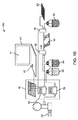
図1Aは、サイズの異なる細胞12を含む不均一溶液から細胞12を単離するマイクロ流体デバイス10を示す。マイクロ流体デバイス10は、細胞12を単離するために使用するように図1Aに示されているが、マイクロ流体デバイス10は、粒子(図示せず)の分離に関連して使用することができると解するべきである。したがって、ここでの用語「細胞」の使用は、粒子に置き換えることができる。図1Aに見られるように、マイクロ流体デバイス10は、インレット18とアウトレット20に接続したマイクロ流体チャネル16を含む基板14を具える。マイクロ流体チャネル16の寸法は、様々である。一例として、マイクロ流体チャネルは幅50μm、高さ70μmである。マイクロ流体チャネル16の幅の典型的な寸法は、20μm乃至200μmの範囲である。マイクロ流体チャネル16の高さの典型的な寸法は、20μm乃至500μmの範囲である。長さも様々であるが、一般的に長さ数センチメートル(例えば、4.5cm)である。基板14は、マイクロ流体デバイスに使用される従来の材料でできている。これらの材料には、ガラス、シリコン、あるいはポリジメチルシロキサン(PDMS)がある。PDMSでは、マイクロ流体デバイス10を作るのにソフトリソグラフィ技術を用いることができる。PDMSの実施例では、モールド作成用に、4インチのシリコンウエファを厚さ70μmのネガティブフォトレジスト(KMPR 1050、Microchem)でスピンコートし、設計されたCr−フォトマスクを介して紫外線に露出させ、現像する。PDMS(Sylgard 184, Dow Corning)を、予め準備したモールドに入れて、脱気した。焼成したPDMS鋳造物を、モールドから外して、ピン万力(ピン万力セットA、Techinical Innovations Inc.)でインレット18とアウトレット20をあけた。パンチで穴をあけたPDMS層を、PDMSとスライドグラス表面をともにエアプラズマ(Plasma Cleaner,Harrick Plasma)にかけて、スライドグラスに接続し、デバイスを封入した。
FIG. 1A shows a
図1Aの実施例では、インレット18は実際は、インレット18’とインレット18”の二つのインレットを含む。第1のインレット18’を用いて、不均一な細胞集団12を含む溶液を導入する。第2のインレット18”は、第2の別の溶液を導入するのに使用できる。以下により詳細に説明するように、第2のインレット18”は、洗浄液、標識(例えば、蛍光ラベル、抗体、核酸染料、蛍光発生基質)、あるいはその他の化学物質(例えば、固定剤あるいは透過剤)をマイクロ流体チャネル16に導入するのに使用できる。
In the embodiment of FIG. 1A, the
図1Aに見られるように、インレット18’、18”は、それぞれポンプ22、24に連結されている。各ポンプ22、24を用いて、設定した流速で各溶液をマイクロ流体デバイス10に送達することができる。当業者に知られているどのようなタイプのポンプでも本発明に関連して使用することができる。このようなポンプには、限定するものではなく、シリンジポンプ、圧搾空気に作用して流体をくみ上げるポンプ、蠕動ポンプ又は容積型ポンプなどがある。図1Aは、マイクロ流体デバイス10と共に使用するシリンジポンプ22、24を示している。例えば、Harvard Apparatus,PHD2000シリンジポンプを用いて、10μl/分乃至4.5ml/分の範囲の全流速を維持することができる。通常は、ポンプ22、24の設定は、マイクロ流体デバイス10を通る流速が100μl/分になるように設定する。
As seen in FIG. 1A, the
図1Aは、システム100の一部として、マイクロ流体デバイス10を制御するのに使用できるコンピュータ40を示す。コンピュータ40は、通常、その中に少なくとも一のプロセッサ42を具えており、コンピュータ40内にある、あるいはコンピュータ40に保存されているソフトウエアを実行する。コンピュータ40はまた、マイクロ流体デバイス10の様々なパラメータを表示するのに使用できるモニタ44を具えている。これらのパラメータには、例えば、ポンプ22、24の流速、ポンプ22、24に含まれる流体の体積、及びその他の操作データがある。コンピュータ40は、好ましくは、ポンプ22、24に、コンピュータ40がポンプ4の個々の流速又は操作状態を調整できるように、接続されている。コンピュータ40は、あらかじめ設定したアルゴリズム又はコンピュータ40に保存している指示セットを用いて、ポンプ22、24を自動的に制御することができる。代替的に、ポンプ22、24の制御を、通常コンピュータとともに使用されるインターフェースデバイス(例えば、キーボード、マウス、その他)を用いて手動で調整できる。
FIG. 1A shows a
溶液交換操作中に、コンピュータ40によって、所望の溶液の流れをマイクロ流体デバイス10で確実に維持することができる。例えば、一のポンプ22が遅くなるか、止まってしまったときに、第2のポンプ24の流速を上げて、所望の流速を確実に維持する。
During the solution exchange operation, the
図1Bは、圧力駆動ポンプシステム46を使用する代替のシステム200を示す。ポンプシステム46は、第1の流体52(例えば、洗浄液)と第2の流体54(例えば、血液)をデバイス10に送り込むのに、レギュレータ50とともに、圧力ガス源48を使用している。このシステム200では、液体用バルブ56、58が、デバイス10のインレットとアウトレットにそれぞれ設けられている。コンピュータ40は、圧力駆動ポンプシステム46と液体用バルブ56、58を制御するように構成されている。例えば、バルブ56を用いて、第1の流体52又は第2の流体54のデバイス10への流れを開閉することができる。バルブ58は、廃液容器60と、例えば、96ウエルプレートを具える回収デバイス62の間のアウトレットの流れを切り替えるのに使用することができる。
FIG. 1B shows an
図1Aに見られるように、マイクロ流体チャネル16は、マイクロ流体チャネル16の長さに沿って選択されたポイントに位置する複数の拡張領域30を具える。拡張領域30は、マイクロ流体チャネル16の幅が急激に増大し、これは、所定の閾値流速であるいはこの流速以上で各拡張領域30内に渦を形成させる、分離した境界層を作る。拡張領域30内にできた渦であり、これがマイクロ流体デバイス10を通って移動する不均一な細胞12の溶液から細胞亜集団12を捕捉する。しかしながら、これらの渦は、慣性を用いて湾曲させたチャネルフローにできるDean渦(J.Wang et al.Vortex−assisted DNA Delivery,Lab Chip,2010,10,2057−2061(2010))や、非対称的に構成されたマイクロチャネルによって形成された渦(Stott,et al.,Isolation of Circulating Tumor Cells Using a Microvortex−Generating Herringbone−Chip,Proc Natl.Acad.Sci.107(43):18392−7(2010)) など流れ方向にできた渦と異なる。以下により詳細に説明するように、所定の閾値あるいはカットオフサイズ(マイクロ流体デバイス10の流速とジオメトリによる)以上の細胞12は、拡張領域30に入り、再循環している渦の中に捕捉又は捕獲される。この閾値サイズより小さい細胞12は捕捉されることなく、マイクロ流体デバイス10の下流側へ流れてゆく。一般的に、最も有効な捕獲は、直径15μmより大きい細胞12に対して生じる。10μmより小さい径では、捕獲効率は低い(例えば5%)。したがって、意味のある捕獲を行うには、捕獲する細胞12の径が≧10μmでなくてはならない。拡張領域30のジオメトリはさまざまである。例えば、拡張領域30は、図1Aに示すように矩形でもよいが、図1C乃至1Gに示すように正方形、三角形、多角形、あるいは半円形プロファイルであってもよい。矩形型の拡張領域30では、主マイクロ流体チャネル16に平行な方向にある拡張領域30の長手側で捕獲能力がより良好である。一般的に、拡張領域30の主壁31(図1Cに示す)は、上流側マイクロ流体チャネル16の流れ方向に対して45°またはそれ以上の角度がついている。
As seen in FIG. 1A, the
図1Cは、上流側マイクロ流体チャネル16に沿った単一の拡張領域30を示している。上述したように、立ち上がりの壁31は、図1Cに破線Aで示す流れの軸に対して45°又はそれ以上角度がついている。これに関して、拡張領域30は、断面寸法(例えば、幅と高さ)が、マイクロ流体チャネル16のすぐ上流側部分における断面寸法に比して、急激に増大している。図1Cの実施例では、立ち上がり壁31は、ちょうど90°より小さい角度がついており、最小限45°の閾値を大きく超えている。拡張領域30はまた、立ち下がり壁33を有している。立ち下がり壁33は、流れ方向Aに対して角度がついていてもよい。一般的に、立ち下がり壁33の角度は重要でなく、どのような角度であってもよい。例えば、一の実施例では、立ち下がり壁33の角度が小さく、立ち下がり壁33を、マイクロ流体チャネル16の幅に対して徐々にテーパさせるようにしてもよい。さらに別の代替例では、立ち下がり壁33がなく、拡張部分がマイクロ流体チャネル16の元の寸法に戻らない。
FIG. 1C shows a
図1Jに示す別の実施例では、拡張領域30は、湾曲した立ち上がり壁31を具える。この点で、立ち上がり壁31は、始めに、マイクロ流体チャネル16の上流側から徐々に開いてゆき、立ち上がり壁31の長さに沿って大きく開いている。この実施例では、立ち上がり壁31の様々なポイントに沿ってひかれた接線が、流れAの軸に比べてかなり異なる角度を有する。例えば、立ち上がり壁31の開始部分近傍では、角度θ1が小さく、45°より小さい。しかし、立ち上がり壁31の終端付近では、角度θ2が急であり、45°以上である。図1Jに示すもののように湾曲したあるいは不連続的な拡張領域30の場合、立ち上がり壁31の全長に沿って、流れAの軸に対する平均角度を表すθAVEが、45°より大きくなくてはならない(θAVE>45°)。
In another embodiment shown in FIG. 1J, the
図1Hは、マイクロ流体チャネル16の長さに沿って設けた複数の拡張領域30の平面図である。図1Iは、図1HのA−A’線に沿った断面図である。図1Hと1Iともに、マイクロ流体チャネル16と拡張領域30の様々な寸法を示す。上述したように、マイクロ流体チャネル16の幅(w)の典型的な寸法は、20μm乃至200μmの範囲である。マイクロ流体チャネル16の高さ(h)の典型的な寸法は、20μm乃至500μmの範囲である。拡張領域30は、80μm乃至800μmの範囲であが、少なくとも80μmでなくてはならない距離(x)を延在している。拡張領域30は、200μm乃至2mmの範囲である距離(y)を延在している。隣接する拡張領域30は、典型的には20μmを超える距離(z)だけ分かれている。いくつかの実施例では、単一の拡張領域30があり、ここでは隣接する拡張領域30がない。マイクロ流体チャネル16の断面プロファイルは、ほぼ矩形、台形、あるいは正方形である。マイクロ加工プロセスは、若干台形の断面を作るか、あるいは若干丸みを帯びたコーナーを作る。チャネル16は、円形又は半円形の断面を有していてもよいが、現在のマイクロ加工技術はこれらのジオメトリを製造しない。ここに述べた方法とデバイスは、これらの変形例に及ぶ。
FIG. 1H is a plan view of a plurality of
図1Aに戻ると、拡張領域30は、マイクロ流体チャネル16の反対側に設けることができる。これによって、単一のマイクロ流体チャネル16がより大きい捕獲能力を有するようになる。更に、以下により詳細に説明するように、この構成によって、多数のチャネル16が平行構造に整列している場合、拡張領域30の千鳥配列が可能になる。すなわち拡張領域30が互いにオフセットして、図3に見られるように隣接するマイクロ流体チャネル16の拡張領域30と交互になるので、隣接するマイクロ流体チャネル16を密に詰めることができる。更に、図1Aを参照すると、より大きいサイズの細胞12が拡張領域30で捕獲される一方、より小さいサイズの細胞12は捕獲されず、マイクロ流体チャネル16を下流側に流れて、アウトレット20から出てゆく。より大きいサイズの細胞12(拡張領域30に示されている細胞)は、拡張領域30内に作られた渦流内に捕獲される。より小さいサイズの細胞12は、そのサイズが小さいため、渦流内に捕獲されず、拡張領域30の外へ出てゆく。したがって、より小さいサイズの細胞12は、拡張領域30の渦で捕獲されることなく、マイクロ流体チャネル16の下流側へ流れ続ける。
Returning to FIG. 1A, the
図2は、サイズの異なる細胞12を含む不均一溶液から細胞12を単離するデバイス10、並びにマイクロ流体チャネル16と拡張領域30内の対応する流れを示す。図2は、マイクロ流体チャネル16と拡張領域30の、A、B、Cで特定される三つの領域を拡大して示す図である。図Aに見られるように、サイズの異なる不均一な細胞集団12が、シリンジポンプ22、24のうちの一方を介してデバイスに送り込まれる。他方のシリンジポンプは、洗浄液あるいはPBSなどのその他の溶液を含んでいてもよい。まず、図Aに示すように、細胞12はy方向にランダムに分散される。細胞12に、二つの対抗する力、すなわち、細胞12をマイクロ流体チャネル16の壁に向かって移動させるよう細胞に作用するせん断勾配揚力(FLせん断勾配)と、マイクロ流体チャネル16の壁から細胞12を遠ざけるウォール効果揚力(FLウォール効果)がかかる。
FIG. 2 shows
断面が矩形のまっすぐなマイクロ流体チャネル16を用いることで、流れている細胞12の動的均衡位置によって、図2の図Bに示すように、動的水平方向均衡位置Xeqと、均一な細胞速度になる。ここで、Xeqは、細胞12の中心とマイクロ流体チャネル16の壁との間の距離として定義される。細胞12が拡張領域30に進むと(図2においては、二つの相対する拡張領域30がある)、より大きいFLせん断勾配がかかっているより大きい細胞12が、渦の中心に向かって押されて捕獲され、一方で、より小さい細胞12は拡張領域30の外にチャネル内へ流されて、アウトレット20へと下流へ流れ続ける。一般的に、FLせん断勾配力は、細胞径(a)の三乗に対応しており、より大きい細胞12にはより大きいFLせん断勾配力がかかる。サイズに応じた水平方向の移動が、細胞12を、細胞12が分離されて残り、その周辺を回る渦の中心に向けて分離下境界線(区分線)を超えて流線の向こう側に駆動する。これによって、切り捨てサイズ以下のサイズを選択する捕獲が可能となり、細胞は区分線を越えて、フォーカスされた流れに残るのに十分な速度で移動せず、アウトレット20から流れ出る。
By using the straight
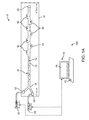
図3は、細胞12を単離するマイクロ流体デバイス10の別の実施例を示す図である。このデバイスはインレット18とアウトレット20に連結された複数のチャネル16を具える。図3は、8つの独立したチャネル16を示しており、これらのチャネルは互いにほぼ平行に配置されている。各マイクロ流体チャネル16は、10個の独立した拡張領域30を有する。もちろん、使用するチャネル16の数はいくつでもよいと解するべきである。同じことが、単一のマイクロ流体チャネル16に沿って設けた拡張領域30の数にも言える。単一のマイクロ流体チャネル16に沿って設けた隣接する拡張領域30間のスペースは、様々であるが、1mmのスペースが機能することが分かっている。追加のチャネル16を加えて、大規模なパラレルデバイス10を作ってもよい。チャネル16は、互いに千鳥配置されている隣接するチャネル16の拡張領域30に対してまっすぐである。この設計により、隣接するチャネル16を互いに密に配置することが可能となり、これによって、マイクロ流体デバイス10の全体的な設置面積が小さくなる。図3は、二次元レイアウトされたチャネル16のアレイを示しているが、このチャネル16のアレイは三次元レイアウトにしてもよい。三次元構造により、スループットを上げることができる。
FIG. 3 is a diagram illustrating another embodiment of the
図3のデバイスでは、マイクロ流体チャネル16が、幅50μm、高さ70μmの、矩形の高アスペクト比を持つチャネルである。インレット18は、細胞12を含むサンプル用の第1のインレット18’と、PBS又はその他の洗浄溶液を含む第2のインレット18”を具える。デュアルインレット18’、18”構成は、マイクロ流体デバイス10内で容易かつ迅速な溶液交換が可能となり、例えば、捕獲されなかった細胞12を洗い流し、回収したサンプルの最終的な濃縮比と純度を強化する手段を提供する。マイクロ流体デバイス10の長さは数センチメートルである。拡張領域30は、所定のコンパクトな設置面積に最大数の拡張領域30を配置するために、交互になったパターンにおかれている。図3に示すデバイスでは、拡張領域が、400μm×400μmの寸法を有する正方形である。
In the device of FIG. 3, the
細胞12が拡張領域30に捕獲されると、渦のサイズを小さくしてゆき、最後になくすことで細胞12は拡張領域30から放出される。これは、入力流速を低減する(例えば、ポンプ22、24の流速を低減する)ことによって行われる。低減させた流速が、渦のサイズを小さくして、そこに捕獲されている細胞12をマイクロ流体チャネル16の流れの中に放出させ、デバイスのアウトレット20へ運ぶ。図3に示すデバイスでは約4ml/分の流速が、最も良いことが分かっている。代替的に、流速を急にほぼゼロになるまで小さくして、マイクロ流体デバイス10を流れる流体の流れを止めるようにしてもよい。この代替例では、オフチップではなく、オンチップで細胞12を回収することができる。
When the
実施例1:稀ながん細胞の血液からの濃縮
図3のマイクロ流体デバイス10を、正常な人の血液細胞(直径2乃至15μm)からがん細胞(直径20μm)を分離して集中させるのに適用し、高スループットでサイズベースの濃縮及び集中させる有用性を示した。血液から濃縮及び集中させたがん細胞は、循環腫瘍細胞(CTCs)が患者の状態に関する情報をリアルタイムで提供することができ、がん治療をモニタリングできるので、臨床診断に特に重要である。生存CTCsを血液から迅速、有効、かつ標識のないアプローチで単離することは、依然として技術的に非常に難しい。CTCsは、10億の血液細胞につき一の細胞というほど低い割合の稀な事象である。現在の戦略は、診断用のCTCsの計数に注目が集まっているが、研究目的で生存CTCsのより大きいサンプルを集めることが緊急目的である。このことは、大きな血液体積をより高いスループットで処理し、修飾した基質又は磁気ビーズに目的の細胞をつけることなく濃縮することが必要であり、更なる分析又は培養のために、捕捉した細胞を個々に選択するアドバンテージを提供している。
Example 1: Concentration of rare cancer cells from blood The
このデバイス10は、稀な細胞を、mL/分の範囲で液体体積を処理し、サイズと密度をベースにした分離を行って目的の細胞を濃縮し、捕獲した細胞をより小さい濃縮した体積にして放出する、大規模な平行デバイスで濃縮するという要望に取り組むものである。稀な細胞濃縮を示すために、希釈したヒトの血液中にスパイクさせた蛍光ラベルを行った乳がん細胞(MCF−7)を、図3に示すデバイスと同様のデバイス10に、4.4mL/分の速度で注入した。MCF7の乳がん細胞を、10%のFBSと、1%の牛のインスリンと、1%のペニシリン/ストレプトマイシンで補填したDMEMを含む媒体で培養し、使用する前にトリプシン処理を行って再度懸濁させた。血液は、健康な人間のポランティアから、訓練された外科医が回収し、実験用にPBS中で5乃至20%に希釈した。
The
これらの高い流速では、上流側渦タンクにチャネルの変形が見られたが、周囲圧力により近いところで作動する下流側の渦チャンバは変形しないことを考えると、捕獲は影響を受けない。より高い操作流速は、むしろ結合強度によって制限を受ける。 At these high flow rates, channel deformation was seen in the upstream vortex tank, but capture is not affected given that the downstream vortex chamber operating closer to ambient pressure does not deform. Higher operating flow rates are rather limited by bond strength.
単細胞と2−4細胞クラスタに含まれるクラスタ細胞としてのスパイクMCF−7細胞は、臨床サンプルに有意なレベルで存在していることが示されていた。血液細胞とがん細胞が、図4Aの上側パネルにある単一の拡張領域30の図に示すように、注入ステップの間に渦の中に入り周回するのが観察された。図4Aの下側パネルは、拡張領域30中に含まれる赤血球細胞と共に捕獲されたがん細胞を示す顕微鏡画像である。赤血球細胞は、希釈サンプルを用いた実験では同じサイズの粒子が渦の中へ移動しなかった場合でも、渦に入ることが観察された。同様に、高い細胞濃度は、細胞間に衝突と流体力学的攪乱を誘発し、クロスストリームの移動と渦へ入ることを引き起こす。
Spike MCF-7 cells as cluster cells contained in single cells and 2-4 cell clusters have been shown to be present at significant levels in clinical samples. Blood and cancer cells were observed to enter the vortex and circulate during the injection step, as shown in the single expanded
更に、各拡張領域30が維持される細胞の最大容量がある。渦が拡張領域30全体を占めた後、最大で〜40単細胞MCF7をより高い流速範囲以上で維持することができる。ほとんどのスパイク実験条件は、この最大値以下に保たれた。溶液が完全に処理されると、渦で捕獲した細胞を、渦をこわすことなくPBSで洗浄した。このことは、図4Bの上側パネルに示されている。図4Bの下側パネルは、より小さく密度の高いRBCsを除去するために、PBS洗浄溶液を導入した後も捕獲されたがん細胞を示す顕微鏡画像である。興味深いことに、最初に渦に入った血液細胞は安定的に捕獲されずトラップからシステムの外にまたすぐに出てしまい、周回しているより大きい安定的に捕獲されたがん細胞を残すことが観察された。赤血球細胞と白血球細胞は、両方ともより密度が高く及び/又はサイズがより小さいため、安定した周回を形成できない。洗浄した細胞は、特性評価と計数用に、96−ウエル−プレートのうちの一のウエルに放出した。
Furthermore, there is a maximum capacity of cells in which each
マイクロ流体デバイス10は、目標細胞濃度、濃縮、及び純度の重要な数値指標を定量化する場合に、良好に機能する。〜500がん細胞でスパイクした5%v/vの血液(例えば、0.5mLの全血、または、〜25億の血液細胞)の10mL容量の血液細胞(n≧6サンプル)を、比較的少量の血液細胞コンタミネーションで、<3分間、200mLより少ない最終容量へ濃縮した(20倍の容量濃縮)。これは、図5Aに見られるように、3.4百万の濃縮比(出力溶液中の混入血液細胞に対する目標がん細胞の比を、入力溶液中の同じ比で除したもの)に該当する。この高い濃縮レベルによって、200mLの最終容量にいて高純度のがん細胞を導出する:図5Bに見られるように、〜40%(平均で、102±21のがん細胞、及び221±155の血液細胞)である。マイクロ流体デバイス10とサンプルで処理したスパイクがん細胞(n=3)がない血液サンプルがウエルに回収され、これは772±283の赤血球細胞と、4±1CD45+の赤血球細胞を有することが分かった。これは、スパイク血液サンプルを用いてマイクロウエルに見られる血液細胞混入量と同じである。達成した濃縮レベルは、百万乃至一千万の濃縮を報告している目標細胞を分離する分子親和性ベース及びフィルターベースのアプローチと比較できる。処理したサンプルの純度は、9.2乃至14.0%のスパイクがん細胞の純度を報告している親和性ベースのアプローチに比較して、高い。処理したサンプル中の血液の希釈を少なくすることで細胞処理スループットが上がるが、スパイク細胞の捕獲効率は下がる。図5Cに示すように、血液濃度が高くなり、捕獲効率が下がり、10乃至20%のスパイクがん細胞が回収された。より高い血液濃度によって、流体渦のサイズと位置を変化させる流体粘度がより高くなり、捕獲効率が下がる。
The
この高い血液濃度での比較的低い捕獲効率は、この技術を1乃至10細胞/mLで生じる超稀な細胞を単離するのに有効なものにするためには、高容量の血液を処理しなければならない(10mL又はそれ以上)ことを示唆している。しかしながら、ここに述べたマイクロ流体デバイス10の高いスループット(2cm2のチップに対して〜5mL/分の希釈血液)は、妥当な時間(<30分)内で大容量の操作を行いうることを示している。
This relatively low capture efficiency at high blood concentrations allows high volumes of blood to be processed in order to make this technique effective for isolating extremely rare cells occurring at 1-10 cells / mL. Suggests that it must be (10 mL or more). However, the high throughput of the
マイクロ流体デバイス10に捕捉した細胞は、高い生存レベルを維持した。蛍光生/死アッセイで測定したところ、デバイスを通って細胞を注入した後の細胞の生存には有意な変化は見られなかった(90.1% vs 90.3%初期)。生存細胞は、いくつかのサンプル調整アプリケーションに重要である。マイクロ流体デバイス10で捕捉して放出した細胞は、免疫染色などの標準的な分子アッセイに使用できる。この結果、標識のないスパイク血液サンプルがマイクロ流体デバイス10で濃縮された。次いで、がん細胞は放出され、マイクロウエルで標識した。染色したがん細胞は、サイトケラチン−PEとDAPIに対してポジティブであり、CD45に対してネガティブである。この一のデバイスで濃縮するが、細胞を更なる処理用に小容量に移す能力は、稀な単細胞の分析に大きなアドバンテージを提供する。
Cells captured by the
図4C乃至4Fは、レイノルド数(Rc)270で、図3のマイクロ流体デバイス10を用いて、HeLa細胞でスパイクした血液サンプルを同様に濃縮した結果を示す。マイクロ流体デバイス10は、HeLa細胞が拡張領域30で捕捉されると、PBS洗浄液で洗浄する。捕獲したHeLa細胞は、流速をRC=5に下げることによって拡張領域30から放出させた。図4Gは、細胞濃度に応じたマイクロ流体デバイス10の捕獲効率の比較を示す。細胞数は、マイクロ流体デバイス10を通して処理したスパイクHeLa細胞の数を表す。
4C-4F show the results of similarly enriching a blood sample spiked with HeLa cells using the
実施例2:細胞標識と溶液交換
マイクロ流体デバイス10は、特定分子のマーカーとして細胞を効果的に標識するのに使用することもできる。伝統的な遠心分離機では、一連の標識化及び洗浄ステップを介して細胞サンプルを特定のマーカーとして標識している。これは、標識化試薬を用いて遠心分離管で細胞をインキュベートするステップと、この細胞を卓上遠心分離機でペレットに濃縮するステップと、手動吸引によって非結合標識化試薬を含む上澄み層を除去するステップと、細胞を新しい媒体に手動で再懸濁させるステップを含む。これらの操作は、流体渦内に細胞を捕獲することによってマイクロ流体デバイス10内で行われ、連続して、捕獲されて周回する細胞を標識化試薬に露出させ、更に、PBS洗浄溶液で洗浄する。標識化細胞は、次いで流速を下げることによって、回収バイアルに小容量で放出された。
Example 2: Cell labeling and solution exchange The
図6A乃至6Dは、それぞれ、捕獲(図6A)、第1の溶液交換(図6B),反応(図6C)、及び第2の溶液交換(図6D)を示す。図6E乃至6Hは、それぞれ、マイクロ流体デバイス10に注入したビオチニル化したEpCAMでインキュベートした実際のMCF7細胞の図6A乃至6Dに対応する顕微鏡画像である。図6Eに示すように、細胞が渦に捕獲され、一定の回転及び周回動作を行っている。図6Fは、ストレプタビジンで被覆したマイクロスフェアを用いた第1の溶液交換を示す。ストレプタビジンで被覆したマイクロスフェアは、拡張領域30に入る。図6Gは、ストレプタビジンで被覆したマイクロスフェアのMCF7細胞との連続的な反応を示す。図6Hは、第2の溶液(すなわち、PBS洗浄液)との溶液交換を示す。PBS洗浄液は、非結合マイクロスフェア(矢印A)を除去する。洗浄が完了した後、マイクロ流体デバイス10の流速を下げることで細胞が渦トラップから放出され、特徴化を行うために96ウエルプレートに回収される。図6Hの矢印Bは、2分以上で次第に細胞に結合した粒子を指している。
FIGS. 6A-6D show capture (FIG. 6A), first solution exchange (FIG. 6B), reaction (FIG. 6C), and second solution exchange (FIG. 6D), respectively. 6E-6H are microscopic images corresponding to FIGS. 6A-6D, respectively, of actual MCF7 cells incubated with biotinylated EpCAM injected into
流体渦の中の適所に細胞を安定して保持する能力によって、標識化剤と洗浄溶液との複数の溶液交換を自動化できるフォーマットで行うことが可能である。追加の新しい溶液は、各々、完全に交換するには約100msかかる。同じ標識化反応は、従来の遠心分離ベースのプロセスでは3回の洗浄ステップを含む6回の遠心分離ステップが必要であり、>30分のサンプル調整時間(標識化試薬でのインキュベーション時間を除く)を要する。各遠心分離及び洗浄ステップは、潜在的に一部の細胞が失われ、5乃至10分を要する。 The ability to stably hold cells in place in the fluid vortex can be done in a format that can automate multiple solution exchanges between the labeling agent and the wash solution. Each additional new solution takes about 100 ms to be completely replaced. The same labeling reaction requires 6 centrifugation steps, including 3 wash steps, in a conventional centrifuge-based process,> 30 min sample preparation time (excluding incubation time with labeling reagent) Cost. Each centrifugation and wash step potentially takes 5 to 10 minutes with some cells lost.
高速標識化は、常にリフレッシュした環境の分子標識に露出させるように流体渦の中で回転し周回している細胞によって支援される。換言すると、渦中の標識化試薬の強い還流によって、細胞表面近くに試薬の非常に小さな空乏化した領域ができ、細胞表面により多くの試薬を強い勾配で引き寄せる。この高速標識は、細胞表面上のストレプタビジンで被覆したマイクロスフェアのビオチニル化した抗EpCAM抗体への結合(図6A乃至6H)を調べることによって観察した。マイクロ流体デバイス10中の細胞が、同数のマイクロビーズを5分で蓄積し、標準プロトコルで調整した細胞は30分で蓄積することがわかった。更に、30分後、マイクロ流体デバイス10で標識した細胞は、標準的な方法に比べて細胞あたりに結合したマイクロビーズの数が平均で2倍であった。
Fast labeling is assisted by cells rotating and orbiting in the fluid vortex so that they are always exposed to molecular labels in a refreshed environment. In other words, the strong reflux of the labeled reagent in the vortex creates a very small depleted region of the reagent near the cell surface, attracting more reagent to the cell surface with a strong gradient. This rapid labeling was observed by examining the binding of streptavidin-coated microspheres on the cell surface to biotinylated anti-EpCAM antibodies (FIGS. 6A-6H). It was found that cells in
実施例3:シーケンシャル操作:標識化に続いて行う稀な細胞の濃縮
遠心分離機で行うことができる複数のシーケンシャルのサンプル調整ステップ(例えば、捕獲、蛍光溶液交換、反応及び洗浄)を、図7に示すマイクロ流体デバイス10を用いて成功裏に行った。この実施例では、マイクロ流体デバイス10が、三つのインレット18’、18”、および18’’’を具える。一のインレット18’は、細胞サンプルを送達するのに使用されるシリンジポンプ22に接続されている。第2のシリンジポンプ24は、蛍光剤を送達するのに使用される。第3のシリンジポンプ26は、洗浄液(PBS)を送達するのに使用される。サイズベースの血液からのがん細胞の捕獲、シーケンシャルな蛍光標識、及び、放出した細胞の分析を<1時間で行った。希釈したがん細胞でスパイクしたヒトの血液(10mL)をマイクロ流体デバイス10に〜3分間注入し、がん細胞を濃縮した。次いで、捕獲された細胞を、固定剤(パラホルムアルデヒド)と透過剤で調整し、蛍光抗体(抗サイトケラチンPE&DAPI)で20分間染色した。捕獲、第1の溶液交換、反応、第2の溶液交換のシーケンスは、図8A乃至8Dに示す。次いで、細胞をPBSで<1分間洗浄し、特徴化を行うために96−ウエルプレートに回収した。回収した細胞は、サイトケラチンとDAPIに対してはポジティブであり、流体渦内部にシーケンシャルに捕獲され、パラホルムアルデヒドで固定され、透視化され、抗サイトケラチン−PE&DAPIで標識化した細胞クラスタの蛍光画像を示す図9に見られるように、シーケンシャルなサンプル調整が成功したことがわかる。図10Aに示すように、ビオチニル化した抗サイトケラチン−EpCAMで被覆したMCF7細胞は、ストレプタビジン結合マイクロビーズでの30分後の標準オフチッププロトコルと同じレベルで、<5分以内で被覆した。図11Aは、30分後の細胞集団の上にマイクロビーズを用いた均一な標識を示す。更に、マイクロ流体デバイス10(遠心分離−オンチップ)により、細胞あたりより多数のビーズが結合した。この結果、単一の簡単なプラットフォームでの細胞分析に必要なすべてのサンプル調整プロセスへの完全なルートが示された。
Example 3 Sequential Operation: Rare Cell Concentration Performed Following Labeling Multiple sequential sample preparation steps (eg, capture, fluorescent solution exchange, reaction and wash) that can be performed in a centrifuge are shown in FIG. The
ここに述べたデバイス10と方法は、安価で迅速な循環腫瘍細胞(CTC)の分析に有益である。CTCの検出と計数は、乳がんの状況と予後をモニタする価値のある有望な診断ツールである。CTCは、血流を介して拡散する腫瘍由来の細胞であり、腫瘍の悪性度を反映することができる。CTCは10億個の細胞あたり1個というほど低い割合で生じる稀な事象である。したがって、CTCの単離は、有意な技術的チャレンジを提供する。ここに述べたデバイス10と方法は、CTCと血液細胞間の細胞サイズ差(CTCは、RBCより2−4倍大きい)を利用して、生きたCTCを全血から標識をしない方法で単離できる。デバイス10と方法のその他の潜在的アプリケーションには、母体血液細胞から胎児細胞を単離する工程を含む出生前診断がある。対象となる胎児細胞を、標識化することなく、あるいは外付けの大きな機械を使うことなく単離することができる。
The
マイクロ流体デバイス10は、CTCの単離に特定のアプリケーションを有するが、その他のアプリケーションに、サンプルから得た細胞12の濃縮がある。例えば、拡張領域30で捕獲できるサイズを有する目標の細胞12を捕捉して、サンプル中に濃縮した形で放出される。例えば、尿、胸膜液、腹腔洗浄液などの生物学的源の流体に含まれる細胞12をマイクロ流体デバイス10に流して、ここに含まれる細胞12を濃縮することができる。この点に関して、マイクロ流体デバイス10は、細胞12の濃縮に非常に適している。例えば、容積ベースでは、マイクロ流体デバイス10は、細胞12を、最初の溶液中の細胞12の濃度の10倍又は20倍以上に濃縮することができる。
The
実施例を示して説明したが、ここに開示した本発明の概念の範囲から外れることなく、様々な変形例が考えられる。例えば、ここにはいくつかの実施例が説明されているが、様々な態様あるいは要素がその他の個別の実施例と交換可能であることは自明である。本発明は、したがって、特許請求の範囲の記載及びその均等物以外によっては限定されるものではない。 While the embodiments have been shown and described, various modifications are possible without departing from the scope of the inventive concept disclosed herein. For example, although several embodiments are described herein, it is obvious that various aspects or elements can be interchanged with other individual embodiments. Accordingly, the invention is not limited except as by the appended claims and their equivalents.
Claims (19)
インレットとアウトレットに接続された少なくとも一のマイクロ流体チャネルを有するマイクロ流体デバイスであって、前記少なくとも一のマイクロ流体チャネルが当該チャネルの長さに沿って配置された少なくとも一の拡張領域を具え、前記少なくとも一の拡張領域が、流体の流れに応じて前記少なくとも一の拡張領域内に渦を発生させるように構成された、前記少なくとも一のマイクロ流体チャネルの断面寸法において急激に増大する部分を具える、マイクロ流体デバイスを提供するステップと;
細胞集団を含む溶液を前記インレットに流すステップと;
前記少なくとも一の拡張領域内にできた渦の中の少なくともいくつかの細胞であって、その径が10μmを超えるいくつかの細胞を捕獲するステップと;
前記少なくとも一のマイクロ流体チャネルを通る溶液の流速を下げることによって、前記複数の拡張領域から前記捕獲した細胞を放出するステップと;
を具えることを特徴とする方法。 In a method of isolating cells:
A microfluidic device having at least one microfluidic channel connected to an inlet and an outlet, wherein the at least one microfluidic channel comprises at least one expansion region disposed along the length of the channel; At least one expansion region comprises a rapidly increasing portion in the cross-sectional dimension of the at least one microfluidic channel configured to generate vortices in the at least one expansion region in response to fluid flow Providing a microfluidic device;
Flowing a solution containing a cell population through the inlet;
Capturing at least some of the cells in a vortex created in the at least one expansion region, the diameter of which exceeds 10 μm;
Releasing the captured cells from the plurality of expansion regions by lowering the flow rate of the solution through the at least one microfluidic channel;
A method characterized by comprising.
Applications Claiming Priority (3)
| Application Number | Priority Date | Filing Date | Title |
|---|---|---|---|
| US38284010P | 2010-09-14 | 2010-09-14 | |
| US61/382,840 | 2010-09-14 | ||
| PCT/US2011/051224 WO2012037030A2 (en) | 2010-09-14 | 2011-09-12 | Method and device for isolating cells from heterogeneous solution using microfluidic trapping vortices |
Publications (2)
| Publication Number | Publication Date |
|---|---|
| JP2013541331A JP2013541331A (en) | 2013-11-14 |
| JP5920895B2 true JP5920895B2 (en) | 2016-05-25 |
Family
ID=45832184
Family Applications (1)
| Application Number | Title | Priority Date | Filing Date |
|---|---|---|---|
| JP2013528369A Active JP5920895B2 (en) | 2010-09-14 | 2011-09-12 | Method and device for isolating cells from heterogeneous solutions using microfluidic capture vortices |
Country Status (7)
| Country | Link |
|---|---|
| US (4) | US9133499B2 (en) |
| EP (1) | EP2616551B1 (en) |
| JP (1) | JP5920895B2 (en) |
| CN (2) | CN104741157B (en) |
| AU (2) | AU2011302302B2 (en) |
| CA (1) | CA2809877C (en) |
| WO (1) | WO2012037030A2 (en) |
Families Citing this family (116)
| Publication number | Priority date | Publication date | Assignee | Title |
|---|---|---|---|---|
| WO2012037030A2 (en) | 2010-09-14 | 2012-03-22 | The Regents Of The University Of California | Method and device for isolating cells from heterogeneous solution using microfluidic trapping vortices |
| EP2689254A4 (en) | 2011-03-24 | 2014-09-03 | Anpac Bio Medical Science Co Ltd | Micro-devices for disease detection |
| CN106995780B (en) * | 2011-05-05 | 2019-11-22 | 安派科生物医学科技有限公司 | Tumour cell detector |
| US9541480B2 (en) | 2011-06-29 | 2017-01-10 | Academia Sinica | Capture, purification, and release of biological substances using a surface coating |
| US9103754B2 (en) | 2011-08-01 | 2015-08-11 | Denovo Sciences, Inc. | Cell capture system and method of use |
| US10466160B2 (en) | 2011-08-01 | 2019-11-05 | Celsee Diagnostics, Inc. | System and method for retrieving and analyzing particles |
| US9404864B2 (en) | 2013-03-13 | 2016-08-02 | Denovo Sciences, Inc. | System for imaging captured cells |
| US10564147B2 (en) | 2012-05-25 | 2020-02-18 | The Regents Of The University Of California | Microfluidic systems for particle trapping and separation using cavity acoustic transducers |
| WO2014061631A1 (en) * | 2012-10-15 | 2014-04-24 | 国立大学法人名古屋大学 | Microchannel chip for microparticle separation, microparticle separation method and system for microparticle separation using chip |
| US9857333B2 (en) | 2012-10-31 | 2018-01-02 | Berkeley Lights, Inc. | Pens for biological micro-objects |
| WO2014078779A1 (en) * | 2012-11-16 | 2014-05-22 | Lightstat, Llc | Disposable sample collection method and apparatus |
| US9752181B2 (en) | 2013-01-26 | 2017-09-05 | Denovo Sciences, Inc. | System and method for capturing and analyzing cells |
| JP2016517416A (en) * | 2013-03-15 | 2016-06-16 | アダマ・マクテシム・リミテッド | Termicide composition and method for treating termites |
| US10391490B2 (en) | 2013-05-31 | 2019-08-27 | Celsee Diagnostics, Inc. | System and method for isolating and analyzing cells |
| US9856535B2 (en) | 2013-05-31 | 2018-01-02 | Denovo Sciences, Inc. | System for isolating cells |
| CN114272964B (en) * | 2013-06-25 | 2024-04-23 | 华盛顿大学商业中心 | Self-digitization of sample volumes |
| US11293001B2 (en) | 2013-07-29 | 2022-04-05 | 9493662 Canada Inc. | Microfluidic cell culture systems |
| US9029109B2 (en) * | 2013-08-07 | 2015-05-12 | President And Fellows Of Harvard College | Microfluidic vortex-assisted electroporation system and method |
| KR20160075568A (en) * | 2013-10-16 | 2016-06-29 | 클리어브릿지 바이오메딕스 피티이 엘티디 | Microfluidics Sorter for Cell Detection and Isolation |
| JP6563914B2 (en) * | 2013-10-22 | 2019-08-21 | バークレー ライツ,インコーポレイテッド | Removing a selected group of micro objects from a microfluidic device |
| SG10202002543UA (en) | 2013-10-22 | 2020-05-28 | Berkeley Lights Inc | Micro-fluidic devices for assaying biological activity |
| DK3060912T3 (en) * | 2013-10-22 | 2020-09-28 | Berkeley Lights Inc | PROCEDURE AND MICROFLUID DEVICE FOR ANALYSIS OF BIOLOGICAL ACTIVITY |
| DK3060645T3 (en) * | 2013-10-22 | 2019-04-08 | Berkeley Lights Inc | MICROFLUID DEVICES WITH INSULATION DISEASES AND METHODS FOR TESTING BIOLOGICAL MICRO-OBJECTS |
| IL283153B2 (en) | 2013-10-22 | 2023-04-01 | Berkeley Lights Inc | Microfluidic devices having isolation pens and methods of testing biological micro-objects with same |
| US9889445B2 (en) | 2013-10-22 | 2018-02-13 | Berkeley Lights, Inc. | Micro-fluidic devices for assaying biological activity |
| SG2013090790A (en) * | 2013-12-04 | 2015-07-30 | Clearbridge Mfluidics Pte Ltd | A microfluidic device |
| WO2015156876A2 (en) * | 2014-01-17 | 2015-10-15 | Massachusetts Institute Of Technology | Integrated electrical profiling system for measuring leukocytes activation from whole blood |
| CN106662514A (en) | 2014-04-01 | 2017-05-10 | 中央研究院 | Methods and systems for cancer diagnosis and prognosis |
| US11192107B2 (en) | 2014-04-25 | 2021-12-07 | Berkeley Lights, Inc. | DEP force control and electrowetting control in different sections of the same microfluidic apparatus |
| US20150306599A1 (en) | 2014-04-25 | 2015-10-29 | Berkeley Lights, Inc. | Providing DEP Manipulation Devices And Controllable Electrowetting Devices In The Same Microfluidic Apparatus |
| WO2015200857A1 (en) * | 2014-06-27 | 2015-12-30 | The Regents Of The University Of California | Apparatus and method for label-free analysis of rare cells from bodily fluids |
| WO2016011059A1 (en) * | 2014-07-14 | 2016-01-21 | President And Fellows Of Harvard College | Drug cocktail analyses using microscale vortex-assisted electroporation |
| EP2998026B1 (en) | 2014-08-26 | 2024-01-17 | Academia Sinica | Collector architecture layout design |
| FI127992B (en) * | 2014-08-29 | 2019-07-15 | Svanbaeck Sami | Method and system for determining dissolution properties of matter |
| CN110918142B (en) | 2014-12-08 | 2022-10-25 | 伯克利之光生命科技公司 | Directional flow actuated microfluidic structures in microfluidic devices and methods of using the same |
| CN107206377B (en) | 2014-12-09 | 2020-02-11 | 伯克利之光生命科技公司 | Automated detection of positive assay regions in microfluidic devices |
| EP3919892A1 (en) | 2014-12-09 | 2021-12-08 | Berkeley Lights, Inc. | Automated detection and repositioning of micro-objects in microfluidic devices |
| WO2016094715A2 (en) | 2014-12-10 | 2016-06-16 | Berkeley Lights, Inc. | Movement and selection of micro-objects in a microfluidic apparatus |
| US10987670B2 (en) | 2015-04-14 | 2021-04-27 | President And Fellows Of Harvard College | Electrode array for vortex-assisted electroporation |
| US10751715B1 (en) | 2015-04-22 | 2020-08-25 | Berkeley Lights, Inc. | Microfluidic reporter cell assay methods and kits thereof |
| US10101250B2 (en) | 2015-04-22 | 2018-10-16 | Berkeley Lights, Inc. | Manipulation of cell nuclei in a micro-fluidic device |
| KR102538721B1 (en) | 2015-04-22 | 2023-05-31 | 버클리 라잇츠, 인크. | Microfluidic cell culture |
| EP3285927A2 (en) | 2015-04-22 | 2018-02-28 | Berkeley Lights, Inc. | Freezing and archiving cells on a microfluidic device |
| WO2016205742A1 (en) * | 2015-06-17 | 2016-12-22 | The Regents Of The University Of California | High efficiency microfluidic device for trapping circulating tumor cells |
| KR101684138B1 (en) * | 2015-06-30 | 2016-12-21 | 한국표준과학연구원 | Apparatus and method for small degree off-axis micro-channel system to improve performance of solution immersed silicon biosensors |
| US9862941B2 (en) | 2015-10-14 | 2018-01-09 | Pioneer Hi-Bred International, Inc. | Single cell microfluidic device |
| US10799865B2 (en) | 2015-10-27 | 2020-10-13 | Berkeley Lights, Inc. | Microfluidic apparatus having an optimized electrowetting surface and related systems and methods |
| KR20180085783A (en) | 2015-11-23 | 2018-07-27 | 버클리 라잇츠, 인크. | In situ-generated microfluidic isolation structures, kits, and methods of use thereof |
| CA3005077C (en) | 2015-12-08 | 2023-02-28 | Berkeley Lights, Inc. | In situ-generated microfluidic assay structures, related kits, and methods of use thereof |
| CA3009073A1 (en) | 2015-12-30 | 2017-07-06 | Berkeley Lights, Inc. | Microfluidic devices for optically-driven convection and displacement, kits and methods thereof |
| TWI808934B (en) | 2015-12-31 | 2023-07-21 | 美商伯克利之光生命科技公司 | Tumor infilitrating cells engineered to express a pro-inflammatory polypeptide |
| EP3889176A1 (en) | 2016-01-15 | 2021-10-06 | Berkeley Lights, Inc. | Methods of producing patient-specific anti-cancer therapeutics and methods of treatment therefor |
| US10107726B2 (en) | 2016-03-16 | 2018-10-23 | Cellmax, Ltd. | Collection of suspended cells using a transferable membrane |
| EP3429753A4 (en) | 2016-03-16 | 2019-11-06 | Berkeley Lights, Inc. | Methods, systems and devices for selection and generation of genome edited clones |
| US10675625B2 (en) | 2016-04-15 | 2020-06-09 | Berkeley Lights, Inc | Light sequencing and patterns for dielectrophoretic transport |
| EP3446102A4 (en) | 2016-04-15 | 2020-01-15 | Berkeley Lights, Inc. | Methods, systems and kits for in-pen assays |
| US20190168221A1 (en) * | 2016-04-15 | 2019-06-06 | Vortex Biosciences, Inc. | Microfluidic Chips and Cartridges and Systems Utilizing Microfluidic Chips and Cartridges |
| SG11201809539RA (en) | 2016-05-26 | 2018-12-28 | Berkeley Lights Inc | Covalently modified surfaces, kits, and methods of preparation and use |
| WO2017214323A1 (en) * | 2016-06-08 | 2017-12-14 | The Regents Of The University Of California | Method and device for processing tissues and cells |
| CN109952106B (en) | 2016-07-21 | 2022-08-05 | 伯克利之光生命科技公司 | Sorting T lymphocytes in a microfluidic device |
| WO2018039084A1 (en) * | 2016-08-20 | 2018-03-01 | The Regents Of The University Of California | High-throughput system and method for the temporary permeablization of cells |
| US10717086B2 (en) * | 2016-08-29 | 2020-07-21 | The Regents Of The University Of California | Integrated system for isolation and emulsification of particles and cells |
| WO2018071448A1 (en) | 2016-10-11 | 2018-04-19 | The Regents Of The University Of California | Systems and methods to encapsulate and preserve organic matter for analysis |
| CN107955788A (en) * | 2016-10-14 | 2018-04-24 | 中国科学院大连化学物理研究所 | A kind of micro fluid dynamcis method on organ chip |
| WO2018119296A1 (en) * | 2016-12-22 | 2018-06-28 | The Charles Stark Draper Laboratory, Inc. | System and method of using a microfluidic electroporation device for cell treatment |
| AU2017388874A1 (en) | 2016-12-30 | 2019-07-18 | Berkeley Lights, Inc. | Methods for selection and generation of genome edited T cells |
| US11213823B2 (en) * | 2017-01-11 | 2022-01-04 | The Regents Of The University Of California | Microfluidic in situ labelling on stable interfaces |
| CN106823475B (en) * | 2017-02-07 | 2023-01-24 | 重庆科技学院 | Blood shunt |
| US11213824B2 (en) | 2017-03-29 | 2022-01-04 | The Research Foundation For The State University Of New York | Microfluidic device and methods |
| US10544413B2 (en) | 2017-05-18 | 2020-01-28 | 10X Genomics, Inc. | Methods and systems for sorting droplets and beads |
| EP3625353B1 (en) | 2017-05-18 | 2022-11-30 | 10X Genomics, Inc. | Methods and systems for sorting droplets and beads |
| US11517901B2 (en) | 2017-06-09 | 2022-12-06 | The Regents Of The University Of California | High-efficiency particle encapsulation in droplets with particle spacing and downstream droplet sorting |
| WO2018227210A1 (en) * | 2017-06-09 | 2018-12-13 | The Regents Of The University Of California | High-efficiency encapsulation in droplets based on hydrodynamic vortices control |
| EP3655776A2 (en) * | 2017-07-18 | 2020-05-27 | Avectas Limited | Payload delivery across cell membranes using continuous flow fluidic system |
| US10549279B2 (en) | 2017-08-22 | 2020-02-04 | 10X Genomics, Inc. | Devices having a plurality of droplet formation regions |
| JP6980904B2 (en) | 2017-08-29 | 2021-12-15 | バイオ−ラッド ラボラトリーズ インコーポレイテッド | Systems and methods for isolating and analyzing cells |
| EP3655158A1 (en) * | 2017-09-07 | 2020-05-27 | Sony Corporation | Particle capturing chamber, particle capturing chip, particle capturing method, apparatus, and particle analysis system |
| WO2019067319A2 (en) * | 2017-09-29 | 2019-04-04 | Schlumberger Technology Corporation | Microfluidic technique for detection of multi-contact miscibility |
| WO2019075409A1 (en) | 2017-10-12 | 2019-04-18 | The Regents Of The University Of California | Microfluidic label-free isolation and identification of cells using fluorescence lifetime imaging (flim) |
| EP3721209B1 (en) | 2017-10-15 | 2024-02-07 | Berkeley Lights, Inc. | Methods for in-pen assays |
| US11499127B2 (en) | 2017-10-20 | 2022-11-15 | The Regents Of The University Of California | Multi-layered microfluidic systems for in vitro large-scale perfused capillary networks |
| US11745179B2 (en) | 2017-10-20 | 2023-09-05 | The Regents Of The University Of California | Microfluidic systems and methods for lipoplex-mediated cell transfection |
| WO2019083852A1 (en) | 2017-10-26 | 2019-05-02 | 10X Genomics, Inc. | Microfluidic channel networks for partitioning |
| JP2019086340A (en) * | 2017-11-02 | 2019-06-06 | シスメックス株式会社 | Cell detection method and cell detection system |
| CN107974392A (en) * | 2017-12-27 | 2018-05-01 | 深圳市合川医疗科技有限公司 | A kind of method of circulating tumor cell in micro-fluidic chip and separating trap blood |
| CN108359577B (en) * | 2018-01-29 | 2022-03-04 | 燕山大学 | Zebra fish egg rotation micro-operation system based on micro-fluid drive and control method |
| KR102019602B1 (en) * | 2018-06-01 | 2019-09-06 | 주종일 | Microfluidic Chip for 3-Dimensional Cell Culture and Method of 3-Dimensional Cell Culture Using the Same |
| US20210163866A1 (en) * | 2018-08-21 | 2021-06-03 | Hewlett-Packard Development Company, L.P. | Cell measurements after isolation from solutions in a microfluidic channel |
| CN108854892B (en) * | 2018-08-23 | 2020-08-25 | 浙江工业大学上虞研究院有限公司 | Micro-reactor |
| CN109666584A (en) * | 2018-12-29 | 2019-04-23 | 北京工业大学 | A kind of experimental provision can be used for carrying out circulating tumor cell sorting experiment |
| KR20210119437A (en) * | 2019-01-23 | 2021-10-05 | 하플로믹 테크놀로지즈 피티와이 엘티디 | microfluidic device |
| IT201900002777A1 (en) * | 2019-02-26 | 2020-08-26 | Menarini Silicon Biosystems Spa | METHOD AND MICROFLUIDIC SYSTEM FOR THE ISOLATION OF PARTICLES |
| EP3939701A4 (en) * | 2019-03-12 | 2023-05-10 | MxT Biotech | Microfluidic system for intracellular delivery of substances and method therefor |
| US10633693B1 (en) | 2019-04-16 | 2020-04-28 | Celsee Diagnostics, Inc. | System and method for leakage control in a particle capture system |
| CN109975265B (en) * | 2019-04-22 | 2020-06-16 | 中国矿业大学 | Three-dimensional contraction and expansion microfluidic device and method for multidirectional induced Dean flow |
| CN114126762B (en) | 2019-04-30 | 2023-01-03 | 伯克利之光生命科技公司 | Methods for encapsulating and assaying cells |
| US11578322B2 (en) | 2019-05-07 | 2023-02-14 | Bio-Rad Laboratories, Inc. | System and method for automated single cell processing |
| US11273439B2 (en) | 2019-05-07 | 2022-03-15 | Bio-Rad Laboratories, Inc. | System and method for target material retrieval from microwells |
| CN111909823B (en) * | 2019-05-08 | 2023-04-18 | 清华大学 | Inertial micro-fluidic chip for enriching circulating tumor cells |
| KR20220033484A (en) | 2019-06-14 | 2022-03-16 | 바이오 래드 래버러토리스 인코오포레이티드 | Systems and Methods for Automated Single Cell Processing and Analysis |
| CN110257223A (en) * | 2019-07-15 | 2019-09-20 | 北京工业大学 | A kind of cell micro-environment regulation chip apparatus based on groove droplet capture |
| AU2020380721B2 (en) * | 2019-11-06 | 2023-11-09 | Korea University Research And Business Foundation | Droplet deformation-based method of transferring material into cells and chip for same |
| CN111060364A (en) * | 2019-11-20 | 2020-04-24 | 天津大学 | Integrated method for staining and screening tumor cells and matched microfluidic chip |
| CN111040928B (en) * | 2019-12-27 | 2023-12-26 | 天津大学 | High-flux micro-fluidic chip for Crypthecodinium cohnii treatment and collection |
| US20230033651A1 (en) * | 2020-01-08 | 2023-02-02 | The General Hospital Corporation | Microfluidic systems and methods for low-shear isolation of rare cells from large sample volumes |
| CN111088146A (en) * | 2020-01-09 | 2020-05-01 | 天津大学 | Micro-fluidic chip for screening tumor cells from pleural effusion |
| CN111207988B (en) * | 2020-02-18 | 2021-08-27 | 中南大学 | Ore pulp monitoring devices based on microfluid |
| US11504719B2 (en) | 2020-03-12 | 2022-11-22 | Bio-Rad Laboratories, Inc. | System and method for receiving and delivering a fluid for sample processing |
| CN111690534B (en) * | 2020-06-16 | 2023-05-30 | 东南大学 | Tumor cell multistage sorting device based on viscoelastic focusing technology |
| WO2022067174A1 (en) * | 2020-09-28 | 2022-03-31 | Georgia Tech Research Corporation | Microfluidic devices for particle capture and methods thereof |
| US11959186B2 (en) * | 2020-11-26 | 2024-04-16 | Changxin Memory Technologies, Inc. | Electroplating method and electroplating apparatus |
| EP4019131A1 (en) | 2020-12-22 | 2022-06-29 | Albert-Ludwigs-Universität Freiburg | Microfluidic device and method for isolating objects |
| USD1016323S1 (en) | 2021-04-09 | 2024-02-27 | Ananda Devices Inc. | Microfluidic slab |
| USD1004128S1 (en) | 2021-04-09 | 2023-11-07 | Ananda Devices Inc. | Microfluidic slab |
| CN113528447A (en) * | 2021-06-10 | 2021-10-22 | 广州市第一人民医院(广州消化疾病中心、广州医科大学附属市一人民医院、华南理工大学附属第二医院) | Micro-fluidic chip and application thereof in sorting, amplifying and recycling tumor stem cells |
| CN114395463B (en) * | 2021-12-10 | 2023-11-17 | 广州大学 | CTC enrichment and release system based on micro-fluidic and micro-optical tweezers arrays and preparation method |
Family Cites Families (24)
| Publication number | Priority date | Publication date | Assignee | Title |
|---|---|---|---|---|
| US6252375B1 (en) * | 2000-07-24 | 2001-06-26 | In-System Design, Inc. | Power management system and current augmentation and battery charger method and apparatus for a computer peripheral |
| GB2375399A (en) * | 2001-05-11 | 2002-11-13 | Suisse Electronique Microtech | Microfluidic system for the manipulation and concentration of particles suspended in fluid |
| ATE510605T1 (en) | 2003-03-14 | 2011-06-15 | Univ Columbia | SYSTEMS AND METHODS FOR BLOOD BASED THERAPY USING A MEMBRANELESS MICROFLUID EXCHANGE DEVICE |
| US7767435B2 (en) * | 2003-08-25 | 2010-08-03 | University Of Washington | Method and device for biochemical detection and analysis of subcellular compartments from a single cell |
| WO2005036139A1 (en) * | 2003-10-03 | 2005-04-21 | Vrije Universiteit Brussel | Method and device for size-separating particles present in a fluid |
| US7803599B2 (en) | 2004-01-16 | 2010-09-28 | University Of Washington | Steady streaming particle traps |
| US20060079003A1 (en) * | 2004-10-12 | 2006-04-13 | Witty Thomas R | Apparatus and method for a precision flow assay |
| US7682817B2 (en) * | 2004-12-23 | 2010-03-23 | Kimberly-Clark Worldwide, Inc. | Microfluidic assay devices |
| CN101137440A (en) * | 2005-01-12 | 2008-03-05 | 因弗因斯医药瑞士股份有限公司 | A method of producing a microfluidic device and microfluidic devices |
| US7993821B2 (en) | 2005-08-11 | 2011-08-09 | University Of Washington | Methods and apparatus for the isolation and enrichment of circulating tumor cells |
| US8186913B2 (en) | 2007-04-16 | 2012-05-29 | The General Hospital Corporation | Systems and methods for particle focusing in microchannels |
| US8841135B2 (en) | 2007-06-20 | 2014-09-23 | University Of Washington | Biochip for high-throughput screening of circulating tumor cells |
| TW200920841A (en) * | 2007-09-25 | 2009-05-16 | Cytyc Corp | Microfluidic apparatus for manipulating imaging and analyzing cells of a cytological specimen |
| CN101177663A (en) * | 2007-11-05 | 2008-05-14 | 吉林大学 | DNA separating micro-fluidic chip |
| FR2931085B1 (en) * | 2008-05-13 | 2011-05-27 | Commissariat Energie Atomique | METHOD OF SORTING PARTICLES OR AMAS FROM PARTICLES IN A FLUID CIRCULATING IN A CHANNEL |
| FR2931079B1 (en) | 2008-05-13 | 2010-07-30 | Commissariat Energie Atomique | DEVICE AND METHOD FOR SEPARATING A SUSPENSION |
| FR2931141B1 (en) | 2008-05-13 | 2011-07-01 | Commissariat Energie Atomique | MICROFLUIDIC SYSTEM AND METHOD FOR THE SORTING OF AMAS FROM CELLS AND PREFERENCE FOR CONTINUOUS ENCAPSULATION THROUGH THEIR SORTING |
| CA2736178A1 (en) | 2008-09-05 | 2010-03-11 | Peter Kuhn | Methods for the detection of circulating tumor cells |
| CN102227637A (en) | 2008-09-26 | 2011-10-26 | 通用医疗公司 | Capturing particles |
| US20110070581A1 (en) | 2009-04-27 | 2011-03-24 | Amit Gupta | Separation of Leukocytes |
| JP2010281701A (en) * | 2009-06-05 | 2010-12-16 | Tohoku Univ | Fine particle continuous sorting/measuring device and micro-fluid chip |
| US8208138B2 (en) | 2009-09-24 | 2012-06-26 | University Of Cincinnati | Spiral microchannel particle separators, straight microchannel particle separators, and continuous particle separator and detector systems |
| SG170702A1 (en) | 2009-10-20 | 2011-05-30 | Agency Science Tech & Res | Microfluidic system for trapping and detection of a biological entity in a sample |
| WO2012037030A2 (en) | 2010-09-14 | 2012-03-22 | The Regents Of The University Of California | Method and device for isolating cells from heterogeneous solution using microfluidic trapping vortices |
-
2011
- 2011-09-12 WO PCT/US2011/051224 patent/WO2012037030A2/en active Application Filing
- 2011-09-12 EP EP11825738.5A patent/EP2616551B1/en active Active
- 2011-09-12 CN CN201510088710.9A patent/CN104741157B/en active Active
- 2011-09-12 US US13/823,112 patent/US9133499B2/en active Active
- 2011-09-12 CA CA2809877A patent/CA2809877C/en active Active
- 2011-09-12 AU AU2011302302A patent/AU2011302302B2/en active Active
- 2011-09-12 CN CN201180044092.8A patent/CN103261436B/en active Active
- 2011-09-12 JP JP2013528369A patent/JP5920895B2/en active Active
-
2015
- 2015-02-23 AU AU2015200910A patent/AU2015200910B2/en active Active
- 2015-08-05 US US14/819,302 patent/US10407709B2/en active Active
- 2015-11-20 US US14/948,119 patent/US10351894B2/en active Active
-
2016
- 2016-11-07 US US15/345,359 patent/US20170114385A1/en not_active Abandoned
Also Published As
| Publication number | Publication date |
|---|---|
| US9133499B2 (en) | 2015-09-15 |
| US20130171628A1 (en) | 2013-07-04 |
| US20150355060A1 (en) | 2015-12-10 |
| CN103261436A (en) | 2013-08-21 |
| AU2011302302B2 (en) | 2014-12-11 |
| WO2012037030A2 (en) | 2012-03-22 |
| AU2015200910B2 (en) | 2016-09-22 |
| CA2809877A1 (en) | 2012-03-22 |
| AU2015200910A1 (en) | 2015-03-12 |
| CA2809877C (en) | 2021-11-23 |
| US20170114385A1 (en) | 2017-04-27 |
| US20160139015A1 (en) | 2016-05-19 |
| CN103261436B (en) | 2015-03-25 |
| US10407709B2 (en) | 2019-09-10 |
| WO2012037030A3 (en) | 2012-06-07 |
| EP2616551A4 (en) | 2016-05-04 |
| CN104741157B (en) | 2017-04-12 |
| US10351894B2 (en) | 2019-07-16 |
| AU2011302302A1 (en) | 2013-03-21 |
| EP2616551A2 (en) | 2013-07-24 |
| EP2616551B1 (en) | 2020-08-19 |
| JP2013541331A (en) | 2013-11-14 |
| CN104741157A (en) | 2015-07-01 |
Similar Documents
| Publication | Publication Date | Title |
|---|---|---|
| JP5920895B2 (en) | Method and device for isolating cells from heterogeneous solutions using microfluidic capture vortices | |
| JP6752338B2 (en) | Microfluidic methods and systems for isolating particle clusters | |
| US10900896B2 (en) | Flow cells utilizing surface-attached structures, and related systems and methods | |
| US9090663B2 (en) | Systems and methods for the capture and separation of microparticles | |
| CA2966611C (en) | Sorting particles in a microfluidic device | |
| Mach et al. | Automated cellular sample preparation using a Centrifuge-on-a-Chip | |
| US9290812B2 (en) | Methods and compositions for separating rare cells from fluid samples | |
| US8263387B2 (en) | Sheath flow devices and methods | |
| CN107828651B (en) | Micro-fluidic chip for preparing single-cell micro-droplet sample | |
| US10697871B2 (en) | Particle isolation/enrichment using continuous closed-loop micro-fluidics | |
| KR101533230B1 (en) | Multistage microfluidic chip and method for selective isolation of sample using the same | |
| JP2019530850A (en) | Method, system, and apparatus for concentrating particles | |
| RU2423698C1 (en) | Method of selective recovery of viable cell population from biological fluids | |
| Tervamäki | Label-free size-based rare cell separation by microfluidics | |
| Garg et al. | Whole-blood sorting, enrichment and in situ immunolabeling of cellular subsets using |
Legal Events
| Date | Code | Title | Description |
|---|---|---|---|
| A621 | Written request for application examination |
Free format text: JAPANESE INTERMEDIATE CODE: A621 Effective date: 20140910 |
|
| A131 | Notification of reasons for refusal |
Free format text: JAPANESE INTERMEDIATE CODE: A131 Effective date: 20150929 |
|
| A521 | Request for written amendment filed |
Free format text: JAPANESE INTERMEDIATE CODE: A523 Effective date: 20151224 |
|
| TRDD | Decision of grant or rejection written | ||
| A01 | Written decision to grant a patent or to grant a registration (utility model) |
Free format text: JAPANESE INTERMEDIATE CODE: A01 Effective date: 20160308 |
|
| A61 | First payment of annual fees (during grant procedure) |
Free format text: JAPANESE INTERMEDIATE CODE: A61 Effective date: 20160406 |
|
| R150 | Certificate of patent or registration of utility model |
Ref document number: 5920895 Country of ref document: JP Free format text: JAPANESE INTERMEDIATE CODE: R150 |
|
| R250 | Receipt of annual fees |
Free format text: JAPANESE INTERMEDIATE CODE: R250 |
|
| R250 | Receipt of annual fees |
Free format text: JAPANESE INTERMEDIATE CODE: R250 |
|
| R250 | Receipt of annual fees |
Free format text: JAPANESE INTERMEDIATE CODE: R250 |
|
| R250 | Receipt of annual fees |
Free format text: JAPANESE INTERMEDIATE CODE: R250 |
|
| R250 | Receipt of annual fees |
Free format text: JAPANESE INTERMEDIATE CODE: R250 |
|
| R250 | Receipt of annual fees |
Free format text: JAPANESE INTERMEDIATE CODE: R250 |