JP5916617B2 - Apparatus and method for brush conditioning and pad conditioning - Google Patents
Apparatus and method for brush conditioning and pad conditioning Download PDFInfo
- Publication number
- JP5916617B2 JP5916617B2 JP2012535203A JP2012535203A JP5916617B2 JP 5916617 B2 JP5916617 B2 JP 5916617B2 JP 2012535203 A JP2012535203 A JP 2012535203A JP 2012535203 A JP2012535203 A JP 2012535203A JP 5916617 B2 JP5916617 B2 JP 5916617B2
- Authority
- JP
- Japan
- Prior art keywords
- axis
- conditioner
- cylindrical rollers
- cylindrical
- rollers
- Prior art date
- Legal status (The legal status is an assumption and is not a legal conclusion. Google has not performed a legal analysis and makes no representation as to the accuracy of the status listed.)
- Active
Links
- 230000003750 conditioning effect Effects 0.000 title claims description 60
- 238000000034 method Methods 0.000 title description 27
- 244000185238 Lophostemon confertus Species 0.000 claims description 17
- 239000000758 substrate Substances 0.000 description 52
- 239000000463 material Substances 0.000 description 41
- 238000012545 processing Methods 0.000 description 28
- 238000004140 cleaning Methods 0.000 description 24
- 238000005498 polishing Methods 0.000 description 16
- 230000008569 process Effects 0.000 description 15
- 239000012530 fluid Substances 0.000 description 12
- 239000011148 porous material Substances 0.000 description 7
- 238000011282 treatment Methods 0.000 description 7
- 239000002245 particle Substances 0.000 description 6
- 239000000126 substance Substances 0.000 description 4
- 150000001875 compounds Chemical class 0.000 description 3
- 230000001143 conditioned effect Effects 0.000 description 3
- 238000010586 diagram Methods 0.000 description 3
- 229920001971 elastomer Polymers 0.000 description 3
- 239000011521 glass Substances 0.000 description 3
- 239000004065 semiconductor Substances 0.000 description 3
- XKRFYHLGVUSROY-UHFFFAOYSA-N Argon Chemical compound [Ar] XKRFYHLGVUSROY-UHFFFAOYSA-N 0.000 description 2
- IJGRMHOSHXDMSA-UHFFFAOYSA-N Atomic nitrogen Chemical compound N#N IJGRMHOSHXDMSA-UHFFFAOYSA-N 0.000 description 2
- 239000004734 Polyphenylene sulfide Substances 0.000 description 2
- 239000004372 Polyvinyl alcohol Substances 0.000 description 2
- 230000008901 benefit Effects 0.000 description 2
- 230000000694 effects Effects 0.000 description 2
- 239000000806 elastomer Substances 0.000 description 2
- 238000004519 manufacturing process Methods 0.000 description 2
- 238000011369 optimal treatment Methods 0.000 description 2
- 239000004033 plastic Substances 0.000 description 2
- 229920003023 plastic Polymers 0.000 description 2
- 229920000642 polymer Polymers 0.000 description 2
- 229920000069 polyphenylene sulfide Polymers 0.000 description 2
- 229920002635 polyurethane Polymers 0.000 description 2
- 239000004814 polyurethane Substances 0.000 description 2
- 229920002451 polyvinyl alcohol Polymers 0.000 description 2
- 238000003672 processing method Methods 0.000 description 2
- 238000012546 transfer Methods 0.000 description 2
- 235000012431 wafers Nutrition 0.000 description 2
- 239000002699 waste material Substances 0.000 description 2
- 235000002754 Acer pseudoplatanus Nutrition 0.000 description 1
- 240000004731 Acer pseudoplatanus Species 0.000 description 1
- 239000004677 Nylon Substances 0.000 description 1
- -1 PTFA Polymers 0.000 description 1
- 235000006485 Platanus occidentalis Nutrition 0.000 description 1
- 239000004952 Polyamide Substances 0.000 description 1
- 239000003082 abrasive agent Substances 0.000 description 1
- 230000009471 action Effects 0.000 description 1
- 229910052782 aluminium Inorganic materials 0.000 description 1
- XAGFODPZIPBFFR-UHFFFAOYSA-N aluminium Chemical compound [Al] XAGFODPZIPBFFR-UHFFFAOYSA-N 0.000 description 1
- 230000003466 anti-cipated effect Effects 0.000 description 1
- 229910052786 argon Inorganic materials 0.000 description 1
- 239000006227 byproduct Substances 0.000 description 1
- 239000000919 ceramic Substances 0.000 description 1
- 229910010293 ceramic material Inorganic materials 0.000 description 1
- 230000008859 change Effects 0.000 description 1
- 239000011248 coating agent Substances 0.000 description 1
- 238000000576 coating method Methods 0.000 description 1
- 238000004891 communication Methods 0.000 description 1
- 238000011109 contamination Methods 0.000 description 1
- 230000008878 coupling Effects 0.000 description 1
- 238000010168 coupling process Methods 0.000 description 1
- 238000005859 coupling reaction Methods 0.000 description 1
- 229910003460 diamond Inorganic materials 0.000 description 1
- 239000010432 diamond Substances 0.000 description 1
- 239000004811 fluoropolymer Substances 0.000 description 1
- 229920002313 fluoropolymer Polymers 0.000 description 1
- 239000006261 foam material Substances 0.000 description 1
- 239000007789 gas Substances 0.000 description 1
- 239000001307 helium Substances 0.000 description 1
- 229910052734 helium Inorganic materials 0.000 description 1
- SWQJXJOGLNCZEY-UHFFFAOYSA-N helium atom Chemical compound [He] SWQJXJOGLNCZEY-UHFFFAOYSA-N 0.000 description 1
- 238000011065 in-situ storage Methods 0.000 description 1
- 239000011261 inert gas Substances 0.000 description 1
- 238000003780 insertion Methods 0.000 description 1
- 230000037431 insertion Effects 0.000 description 1
- 150000002500 ions Chemical class 0.000 description 1
- 239000007788 liquid Substances 0.000 description 1
- 230000014759 maintenance of location Effects 0.000 description 1
- 229910052751 metal Inorganic materials 0.000 description 1
- 239000002184 metal Substances 0.000 description 1
- 150000002739 metals Chemical class 0.000 description 1
- 229910052757 nitrogen Inorganic materials 0.000 description 1
- 229920001778 nylon Polymers 0.000 description 1
- 238000007517 polishing process Methods 0.000 description 1
- 229920002647 polyamide Polymers 0.000 description 1
- 239000004417 polycarbonate Substances 0.000 description 1
- 229920000515 polycarbonate Polymers 0.000 description 1
- 229920001296 polysiloxane Polymers 0.000 description 1
- 239000004810 polytetrafluoroethylene Substances 0.000 description 1
- 229920001343 polytetrafluoroethylene Polymers 0.000 description 1
- 239000005060 rubber Substances 0.000 description 1
- 239000002210 silicon-based material Substances 0.000 description 1
- 230000003746 surface roughness Effects 0.000 description 1
- 229920001169 thermoplastic Polymers 0.000 description 1
- 239000012815 thermoplastic material Substances 0.000 description 1
- 229920001187 thermosetting polymer Polymers 0.000 description 1
- 239000004416 thermosoftening plastic Substances 0.000 description 1
- WFKWXMTUELFFGS-UHFFFAOYSA-N tungsten Chemical compound [W] WFKWXMTUELFFGS-UHFFFAOYSA-N 0.000 description 1
- 229910052721 tungsten Inorganic materials 0.000 description 1
- 239000010937 tungsten Substances 0.000 description 1
- XLYOFNOQVPJJNP-UHFFFAOYSA-N water Substances O XLYOFNOQVPJJNP-UHFFFAOYSA-N 0.000 description 1
Images


Classifications
-
- B—PERFORMING OPERATIONS; TRANSPORTING
- B24—GRINDING; POLISHING
- B24B—MACHINES, DEVICES, OR PROCESSES FOR GRINDING OR POLISHING; DRESSING OR CONDITIONING OF ABRADING SURFACES; FEEDING OF GRINDING, POLISHING, OR LAPPING AGENTS
- B24B1/00—Processes of grinding or polishing; Use of auxiliary equipment in connection with such processes
-
- B08B1/12—
-
- B08B1/32—
-
- B08B1/50—
-
- B08B1/52—
-
- B08B1/54—
-
- B—PERFORMING OPERATIONS; TRANSPORTING
- B08—CLEANING
- B08B—CLEANING IN GENERAL; PREVENTION OF FOULING IN GENERAL
- B08B15/00—Preventing escape of dirt or fumes from the area where they are produced; Collecting or removing dirt or fumes from that area
- B08B15/04—Preventing escape of dirt or fumes from the area where they are produced; Collecting or removing dirt or fumes from that area from a small area, e.g. a tool
-
- B—PERFORMING OPERATIONS; TRANSPORTING
- B08—CLEANING
- B08B—CLEANING IN GENERAL; PREVENTION OF FOULING IN GENERAL
- B08B3/00—Cleaning by methods involving the use or presence of liquid or steam
- B08B3/04—Cleaning involving contact with liquid
- B08B3/041—Cleaning travelling work
-
- B—PERFORMING OPERATIONS; TRANSPORTING
- B24—GRINDING; POLISHING
- B24B—MACHINES, DEVICES, OR PROCESSES FOR GRINDING OR POLISHING; DRESSING OR CONDITIONING OF ABRADING SURFACES; FEEDING OF GRINDING, POLISHING, OR LAPPING AGENTS
- B24B37/00—Lapping machines or devices; Accessories
- B24B37/04—Lapping machines or devices; Accessories designed for working plane surfaces
- B24B37/07—Lapping machines or devices; Accessories designed for working plane surfaces characterised by the movement of the work or lapping tool
- B24B37/08—Lapping machines or devices; Accessories designed for working plane surfaces characterised by the movement of the work or lapping tool for double side lapping
-
- B—PERFORMING OPERATIONS; TRANSPORTING
- B24—GRINDING; POLISHING
- B24B—MACHINES, DEVICES, OR PROCESSES FOR GRINDING OR POLISHING; DRESSING OR CONDITIONING OF ABRADING SURFACES; FEEDING OF GRINDING, POLISHING, OR LAPPING AGENTS
- B24B37/00—Lapping machines or devices; Accessories
- B24B37/11—Lapping tools
- B24B37/20—Lapping pads for working plane surfaces
-
- B—PERFORMING OPERATIONS; TRANSPORTING
- B24—GRINDING; POLISHING
- B24B—MACHINES, DEVICES, OR PROCESSES FOR GRINDING OR POLISHING; DRESSING OR CONDITIONING OF ABRADING SURFACES; FEEDING OF GRINDING, POLISHING, OR LAPPING AGENTS
- B24B53/00—Devices or means for dressing or conditioning abrasive surfaces
- B24B53/017—Devices or means for dressing, cleaning or otherwise conditioning lapping tools
-
- B—PERFORMING OPERATIONS; TRANSPORTING
- B24—GRINDING; POLISHING
- B24D—TOOLS FOR GRINDING, BUFFING OR SHARPENING
- B24D13/00—Wheels having flexibly-acting working parts, e.g. buffing wheels; Mountings therefor
- B24D13/02—Wheels having flexibly-acting working parts, e.g. buffing wheels; Mountings therefor acting by their periphery
- B24D13/12—Wheels having flexibly-acting working parts, e.g. buffing wheels; Mountings therefor acting by their periphery comprising assemblies of felted or spongy material, e.g. felt, steel wool, foamed latex
-
- H—ELECTRICITY
- H01—ELECTRIC ELEMENTS
- H01L—SEMICONDUCTOR DEVICES NOT COVERED BY CLASS H10
- H01L21/00—Processes or apparatus adapted for the manufacture or treatment of semiconductor or solid state devices or of parts thereof
- H01L21/67—Apparatus specially adapted for handling semiconductor or electric solid state devices during manufacture or treatment thereof; Apparatus specially adapted for handling wafers during manufacture or treatment of semiconductor or electric solid state devices or components ; Apparatus not specifically provided for elsewhere
- H01L21/67005—Apparatus not specifically provided for elsewhere
- H01L21/67011—Apparatus for manufacture or treatment
- H01L21/67017—Apparatus for fluid treatment
- H01L21/67028—Apparatus for fluid treatment for cleaning followed by drying, rinsing, stripping, blasting or the like
- H01L21/6704—Apparatus for fluid treatment for cleaning followed by drying, rinsing, stripping, blasting or the like for wet cleaning or washing
- H01L21/67046—Apparatus for fluid treatment for cleaning followed by drying, rinsing, stripping, blasting or the like for wet cleaning or washing using mainly scrubbing means, e.g. brushes
-
- A—HUMAN NECESSITIES
- A46—BRUSHWARE
- A46B—BRUSHES
- A46B13/00—Brushes with driven brush bodies or carriers
- A46B13/001—Cylindrical or annular brush bodies
-
- A—HUMAN NECESSITIES
- A46—BRUSHWARE
- A46B—BRUSHES
- A46B2200/00—Brushes characterized by their functions, uses or applications
- A46B2200/30—Brushes for cleaning or polishing
- A46B2200/3093—Brush with abrasive properties, e.g. wire bristles
Landscapes
- Engineering & Computer Science (AREA)
- Mechanical Engineering (AREA)
- Physics & Mathematics (AREA)
- Condensed Matter Physics & Semiconductors (AREA)
- General Physics & Mathematics (AREA)
- Manufacturing & Machinery (AREA)
- Computer Hardware Design (AREA)
- Microelectronics & Electronic Packaging (AREA)
- Power Engineering (AREA)
- Cleaning Or Drying Semiconductors (AREA)
- Cleaning In General (AREA)
- Mechanical Treatment Of Semiconductor (AREA)
Description
本発明の実施形態は、電子デバイス製造に関係する。特に、実施形態は、半導体基板、ウエハ、コンパクトディスク、ガラス基板、等などの薄いディスクを洗浄するおよび/または研磨するためのスクラバボックスに関係する。 Embodiments of the invention relate to electronic device manufacturing. In particular, embodiments relate to a scrubber box for cleaning and / or polishing thin disks such as semiconductor substrates, wafers, compact disks, glass substrates, and the like.
スクラバまたはスクラバボックスと時には呼ばれるブラシ洗浄装置を、電子デバイス製造プロセスの1つまたは複数のステージにおいて半導体基板を研磨するためおよび/または洗浄するために多くの場合に利用する。例えば、その上に配置されたパッド材料またはブラシ本体を有する円柱状ローラを使用する洗浄デバイスを、基板の主要面から材料を除去するために基板の少なくとも1つの主要面と接触させることができる。1つの典型的なプロセスでは、化学機械研磨(CMP)プロセスを使用して基板を研磨するために、その上に配置されたパッド材料を有する円柱状ローラを、回転する基板に対して回転させ、強く押し付けるようにさせる。別の1つの典型的なプロセスでは、CMPプロセスの後で基板を洗浄するために、その上に配置されたブラシ本体を有する円柱状ローラを、回転する基板に対して回転させ、強く押し付けるようにさせる。 A brush cleaning apparatus, sometimes referred to as a scrubber or scrubber box, is often utilized to polish and / or clean a semiconductor substrate in one or more stages of an electronic device manufacturing process. For example, a cleaning device using a cylindrical roller having a pad material or brush body disposed thereon can be brought into contact with at least one major surface of the substrate to remove material from the major surface of the substrate. In one exemplary process, to polish a substrate using a chemical mechanical polishing (CMP) process, a cylindrical roller having a pad material disposed thereon is rotated relative to the rotating substrate, Make it push hard. In another exemplary process, to clean the substrate after the CMP process, a cylindrical roller having a brush body disposed thereon is rotated and pressed against the rotating substrate. Let
これらの装置において円柱状ローラ上に配置されたパッド材料またはブラシ本体の研磨表面は、時間とともに摩耗する傾向があり、これが除去速度または洗浄効率を低下させる。したがって、所望の研磨結果または洗浄結果を実現するために、パッド材料またはブラシ本体を頻繁に交換する必要がある場合がある。パッド材料またはブラシ本体の交換は、費用がかかり、ダウンタイムを生じさせ、これがより大きな所有コストおよびより低いスループットという結果をもたらす。 In these devices, the pad material disposed on the cylindrical roller or the abrasive surface of the brush body tends to wear over time, which reduces the removal rate or cleaning efficiency. Thus, it may be necessary to frequently replace the pad material or brush body to achieve the desired polishing or cleaning result. Replacement of the pad material or brush body is expensive and results in downtime, which results in higher cost of ownership and lower throughput.
集積回路に対する要求が増加し続けるので、チップ製造業者は、増加したスループットを有する半導体プロセス工作機械設備およびより確固とした処理装置を要求している。かかる要求を満足させるために、スループットを最大にし、機器構成要素の耐用年数を増加させ、所有コストを低下させるために、装置および方法が開発されている。 As the demand for integrated circuits continues to increase, chip manufacturers are demanding semiconductor process machine tool equipment and more robust processing equipment with increased throughput. In order to meet these requirements, devices and methods have been developed to maximize throughput, increase the service life of equipment components, and reduce cost of ownership.
必要とされるものは、表面の摩耗を取り除き、表面から凝集した材料を除去することのほか、パッド材料またはブラシ本体の耐用寿命を延ばすために、円柱状ローラ上に配置されたパッド材料またはブラシ本体の処理表面をリフレッシュさせるための装置および方法である。 What is needed is a pad material or brush placed on a cylindrical roller to remove surface wear and remove agglomerated material from the surface, as well as to extend the useful life of the pad material or brush body. An apparatus and method for refreshing a treated surface of a body.
本明細書において説明する実施形態は、基板研磨システムまたは基板洗浄システムの一部であるブラシボックス内に配置された円柱状ローラの処理表面をコンディショニングするための方法および装置に関係する。一実施形態では、ブラシボックスを記載する。ブラシボックスは、内部容積を有するタンクと、内部容積内に少なくとも部分的に配置された1対の円柱状ローラであって、円柱状ローラの各々がそれぞれの軸の周りを回転可能である、1対の円柱状ローラと、円柱状ローラが互いに近接している第1の位置と円柱状ローラが互いに間隔を空けて離れている第2の位置との間でそれぞれの円柱状ローラを移動させるために、円柱状ローラの各々に連結されたアクチュエータアセンブリと、円柱状ローラの各々のためのコンディショニング装置であって、各コンディショニング装置が内部容積内に配置されたコンディショナを含み、ローラが第2の位置にあるときに、コンディショナが円柱状ローラの各々の外側表面と接触する、コンディショニング装置とを含む。 Embodiments described herein relate to methods and apparatus for conditioning a processing surface of a cylindrical roller disposed within a brush box that is part of a substrate polishing system or substrate cleaning system. In one embodiment, a brush box is described. The brush box is a tank having an internal volume and a pair of cylindrical rollers disposed at least partially within the internal volume, each of the cylindrical rollers being rotatable about a respective axis. To move each cylindrical roller between a pair of cylindrical rollers and a first position where the cylindrical rollers are close to each other and a second position where the cylindrical rollers are spaced apart from each other An actuator assembly coupled to each of the cylindrical rollers, and a conditioning device for each of the cylindrical rollers, wherein each conditioning device is disposed within the internal volume, wherein the rollers are second A conditioning device in which the conditioner contacts the outer surface of each of the cylindrical rollers when in position.
別の一実施形態では、ブラシボックスを記載する。ブラシボックスは、内部容積を有するタンクと、内部容積内に配置された1対の円柱状ローラであって、ローラの各々がそれぞれの第1の軸の周りを回転可能である、1対の円柱状ローラと、ローラが互いに近接している第1の位置とローラが互いに間隔を空けて離れている第2の位置との間でそれぞれのローラを移動させるために、円柱状ローラの各々に連結されたアクチュエータアセンブリと、ローラの各々のためのコンディショニング装置であって、各コンディショニング装置が内部容積内に配置されたコンディショナを含み、ローラが第2の位置にあるときに、各コンディショナが円柱状ローラの各々の外側表面と接触し、各コンディショナが第1の軸とは異なる第2の軸の周りを回転可能である、コンディショニング装置とを含む。 In another embodiment, a brush box is described. The brush box is a tank having an internal volume and a pair of cylindrical rollers disposed within the internal volume, each of the rollers being rotatable about a respective first axis. Connected to each of the cylindrical rollers to move each roller between a columnar roller and a first position where the rollers are close to each other and a second position where the rollers are spaced apart from each other Actuator assembly and a conditioning device for each of the rollers, each conditioning device including a conditioner disposed within the internal volume, wherein each conditioner is circular when the roller is in the second position. A conditioning device in contact with the outer surface of each of the columnar rollers, wherein each conditioner is rotatable about a second axis different from the first axis.
別の一実施形態では、基板を処理するための方法を記載する。本方法は、タンクへ基板を搬送するステップと、タンク内に配置された2つの円柱状ローラの間に基板を設置するステップと、円柱状ローラの各々の処理表面が基板の主要面に接触する第1の位置へと2つの円柱状ローラの各々を移動させるステップと、2つの円柱状ローラのうちの少なくとも1つと基板との間に相対的な運動を与えることによって基板を処理するステップと、基板の主要面から間隔を空けて離れた第2の位置へ2つの円柱状ローラの各々を移動させるステップであって、第2の位置が処理表面をコンディショニング装置と接触させることを含む、移動させるステップと、処理表面をコンディショニングしながらタンクの外へ基板を搬送するステップとを含む。 In another embodiment, a method for processing a substrate is described. The method includes the steps of transporting a substrate to a tank, placing the substrate between two cylindrical rollers disposed in the tank, and each processing surface of the cylindrical roller contacts a major surface of the substrate. Moving each of the two cylindrical rollers to a first position; treating the substrate by providing a relative movement between at least one of the two cylindrical rollers and the substrate; Moving each of the two cylindrical rollers to a second position spaced apart from a major surface of the substrate, wherein the second position comprises contacting the processing surface with a conditioning device. And transporting the substrate out of the tank while conditioning the processing surface.
したがって、本発明の上に記述した特徴を詳細に理解することが可能な方式で、上に簡潔に要約されている本発明のより詳しい説明を、その一部が添付した図面に図示されている実施形態を参照することによって知ることができる。しかしながら、添付した図面が本発明の典型的な実施形態だけを図示し、本発明が他の同様に有効な実施形態を許容することができるので、それゆえ、本発明の範囲を限定するようには見なされないことに、留意すべきである。 Accordingly, a more detailed description of the invention, briefly summarized above, is shown in part in the accompanying drawings in a manner that provides a thorough understanding of the features described above. This can be known by referring to the embodiment. However, the attached drawings only illustrate exemplary embodiments of the invention, and the invention may allow other equally effective embodiments, therefore, so as to limit the scope of the invention Note that is not considered.
理解を容易にするために、可能である場合には、複数の図に共通な同一の要素を示すために、同一の参照番号を使用している。一実施形態において開示した要素を、具体的な記述がなくとも別の実施形態において利益をもたらすように利用することができることが予想される。 To facilitate understanding, identical reference numerals have been used, where possible, to designate identical elements that are common to the figures. It is anticipated that elements disclosed in one embodiment can be utilized to benefit in another embodiment without specific description.
本明細書において説明する実施形態は、スクラバボックスにおいて利用されるブラシ型洗浄システム内で円柱状ローラ上に配置されたパッド材料またはブラシ本体の処理表面をコンディショニングするためまたはリフレッシュするための装置および方法を一般に提供する。本発明による利点に適合することができるスクラバボックスの実施形態は、SYCAMORE(商標)研磨システムおよびDESICA(登録商標)洗浄装置の一部である洗浄モジュールを含み、両者ともSanta Clara、Californiaに所在するApplied Materials,Inc.から入手可能である。本明細書において説明する実施形態を、他の製造業者から入手可能なブラシ型洗浄システムおよび研磨システムにおいてやはり利用することができる。加えて、スクラバボックスの実施形態を、垂直の向きである基板を処理するように説明しているが、ある実施形態を、水平の向きである基板を処理するように構成されたスクラバボックスにおいて利用することができる。 The embodiments described herein provide an apparatus and method for conditioning or refreshing the treatment surface of a pad material or brush body disposed on a cylindrical roller in a brush-type cleaning system utilized in a scrubber box. To the general public. Scrubber box embodiments that can accommodate the benefits of the present invention include a SYCAMORE ™ polishing system and a cleaning module that is part of a DESICA® cleaning device, both located in Santa Clara, California. Applied Materials, Inc. Is available from The embodiments described herein can also be utilized in brush-type cleaning systems and polishing systems available from other manufacturers. In addition, although an embodiment of the scrubber box is described to process substrates that are vertically oriented, certain embodiments may be utilized in a scrubber box that is configured to process substrates that are horizontally oriented. can do.
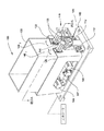
図1は、上に説明したような洗浄モジュールにおいて利用することができるスクラバボックス100の等角図である。スクラバボックス100は、第1の支持体125および第2の支持体130中に少なくとも部分的に入れられているタンク105を含む。支持体125、130の各々を、スクラバボックス100のタンク105に対して外である(すなわち外側にある)リンケージ110に連結する。支持体125、130の各々は、アクチュエータ135を支持するように適合している。各アクチュエータ135を、タンク105の内側に置かれた円柱状ローラ115、120(図2Aに図示する)に連結する。アクチュエータ135は、軸A’およびA”の周りでのそれぞれ円柱状ローラ115、120の回転運動を与える。アクチュエータ135の各々を、軸A’およびA”の周りにそれぞれ円柱状ローラ115、120を回転させるように適合した直接駆動サーボモータなどの駆動モータとすることができる。アクチュエータ135の各々を、円柱状ローラ115、120の回転速度を制御するように適合したコントローラに連結する。
FIG. 1 is an isometric view of a
リンケージ110を、支持体125、130の各々、ベース140、およびアクチュエータ145に連結する。基板101(図2に図示する)の主要面に対して、タンク105の内側に置かれた円柱状ローラ115、120の使いやすく正確な作動/運動のために、リンケージ110を利用する。加えて、ブラシ115、120、アクチュエータ135、および支持体125、130の間の回転連結を実現するために、クリアランスホール(図示せず)をタンク105内に形成することができる。フレキシブルワッシャ、シールまたはベローズなどの柔軟な結合素子150を、各穴の周りに配置することができ、タンク105と支持体125、130との間に装着することができる。かかる配置は、(1)タンク105の壁に対して円柱状ローラ115、120の相対運動を可能にし、(2)別のやり方ではタンク壁中の穴を通してタンク105の内部へと通過するはずの粒子汚染に対して基板101を保護し、および/または(3)流体が穴を通って排出されることを防止する一方で、タンク105内の流体レベルが穴のレベルに達するまたは超えることを可能にする。リンケージ110の運動を制御するために、アクチュエータ145をコントローラに連結する。
第1の支持体125および第2の支持体130を(互いに上側におよび内側に向かって、ならびに/または互いに下側におよび外側に向かって離れて)ピボット回転するように適合させることができるピボット点112によって、第1の支持体125および第2の支持体130の各々をベース140に連結する。動作では、第1の支持体125および第2の支持体130を、ベース140に対して、図1に示したように、それぞれの円弧1461、1462を介して同時に移動させることができる。かかる運動は、第1の円柱状ローラ115および第2の円柱状ローラ120を図2Aに示したように基板101に対して閉じさせることができる、またはスクラバボックス100への基板101の挿入および/またはこれからの取り出しを可能にするために、第1の円柱状ローラ115および第2の円柱状ローラ120を(図2Bに示したように)間の間隔を空けて離すことができる。
A pivot that can be adapted to pivot the
図2Aは、円柱状ローラ115、120が閉じられている、すなわち基板101の主要面に対して押し付けられている処理位置にある円柱状ローラ115、120を示している図1のスクラバボックス100の上面図である。図2Bは、円柱状ローラ115、120が基板の搬送を容易にするように間隔を空けて離れている搬送位置にある図2Aのスクラバボックス100の上面図である。スクラバボックス100はまた、1つまたは複数の駆動モータ144および回転装置147を含む。基板101を支持するようにおよび/または係合するように構成され、基板101の回転を容易にするように構成されたローラアセンブリに、駆動モータ144の各々および回転装置147を連結する。
2A shows the
円柱状ローラ115、120の各々は、その上に配置された管状カバー128を含む。管状カバー128を、基板101を研磨するために利用することができるパッド材料または基板101を洗浄するように適合したブラシ本体から作られた脱着可能なスリーブとすることができる。
Each of the
管状カバー128として利用することができるパッド材料の例は、化学機械研磨(CMP)プロセスにおいて典型的に利用される高分子パッド材料を含む。高分子材料を、ポリウレタン、ポリカーボネート、フロロポリマ、PTFE、PTFA、硫化ポリフェニレン(PPS)、またはこれらの組み合わせとすることができる。パッド材料は、連続気泡または独立気泡発泡ポリマ、エラストマ、フェルト、含浸フェルト、プラスチック、および処理化学薬品に対応する類似の材料をさらに備えることができる。別の一実施形態では、パッド材料は、多孔質コーティングを用いて含浸させたフェルト材料である。
Examples of pad materials that can be utilized as the
管状カバー128として利用することができるブラシ本体の例は、発泡材料(例えば、ポリビニルアルコール(PVA)、ポリウレタン)などの高分子材料、ならびに熱可塑性材料、またはナイロンなどのポリアミド材料を含む。管状カバー128は、基板101を削り落すためおよび基板101の洗浄を引き起こすために利用する複数の盛り上がった形体、小結節、またはブリッスル(図示せず)をさらに含むことができる。
Examples of brush bodies that can be utilized as the
管状カバー128の具体的な材料に応じて、管状カバー128の処理表面の洗浄効果および/または研磨効果は、適した気孔率および平均細孔サイズに一般に依存する。ある実施形態では、管状カバー128の処理表面の気孔率を、約85%よりも大きくすることができる。管状カバー128の他の特性は、望ましい平均細孔サイズまたは開口を含む。細孔サイズ開口は、ある実施形態では約10ミクロンから約200ミクロンまでの範囲である。細孔構造が、基板の機能面の洗浄またはそこからの材料除去をもたらす。研磨コンパウンド保持、研磨活性度または除去活性度、ならびに材料搬送および流体搬送などの属性が、除去速度にやはり影響を及ぼす。
Depending on the specific material of the
基板からの材料の最適な除去を容易にするように、比較的高く安定な除去速度および/または最大にした洗浄効率を提供するために、これらの微視的な細孔を完全にかつ均等に開かせなければならない。これらの細孔構造は、開いているときに、処理表面の濡れ性を向上させることによって、処理表面粗さを維持することによって、および、例えば、研磨コンパウンドから供給される砥粒粒子などの研磨コンパウンドを分散させることによって、材料除去を促進させる。 These microscopic pores are completely and evenly provided to provide a relatively high and stable removal rate and / or maximized cleaning efficiency so as to facilitate optimal removal of material from the substrate. It must be opened. These pore structures, when open, improve the wettability of the treated surface, maintain the treated surface roughness, and polish, for example, abrasive particles supplied from a polishing compound Dispersing the compound facilitates material removal.
研磨プロセスまたは洗浄プロセス中の基板から材料を除去するプロセスにおいて、管状カバー128の処理表面は、摩耗するようになり、除去した材料、化学物質、およびその他の副生成物が管状カバー128の処理表面に付着するようになる。管状カバー128の洗浄効率および/または研磨効率を維持するために、管状カバー128を交換することができる、これはコストがかかり、時間がかかる。あるいは、管状カバー128の処理表面を向上させるために、管状カバー128の処理表面を、定期的にコンディショニングするまたはリフレッシュすることができる。
In the process of removing material from the substrate during the polishing or cleaning process, the treated surface of the
図2Aおよび図2Bは、円柱状ローラ115、120の各々の上に配置された管状カバー128の処理表面をコンディショニングするためおよび/またはリフレッシュするために利用することができるコンディショニング装置200の一実施形態を図示する。この実施形態では、専用のコンディショニング装置200を、円柱状ローラ115、120の各々に対して設けているが、1つだけのコンディショニング装置200を利用することができる。コンディショニング装置200を、1つまたは複数の支持体部材210によってタンク105の側壁205に隣接して装着する。コンディショニング装置200をタンク105の中心から離して設置する、それで、コンディショニング装置200が基板搬送および/または基板研磨プロセスもしくは洗浄プロセスを邪魔しない。しかしながら、第1の支持体125および第2の支持体130を互いに離して下に向けておよび外に向けて作動させるときには、コンディショニング装置200を円柱状ローラ115、120の各々と接触するように設置する。一実施形態では、第1の支持体125および第2の支持体130の移動が、円柱状ローラ115、120をそれぞれのコンディショニング装置200と接触させる。円柱状ローラ115、120がこの位置にあるときには、円柱状ローラ115、120とコンディショニング装置200との間に相対的な運動を生じさせることによって、円柱状ローラ115、120の各々の上に配置された管状カバー128の処理表面を、コンディショニングすることができる。
2A and 2B illustrate one embodiment of a
一実施形態では、円柱状ローラ115、120は、コンディショニング装置200に対してそれぞれの第1の軸A’およびA”の周りを回転する。軸A’およびA”の回転方向は、同じであることも異なることもある。例えば、第1の軸A’および第2の軸A”の回転方向を、両方とも時計回りまたは反時計回りとすることができる。あるいは、第1の軸A’の回転方向を時計回りとすることができ、第2の軸A”の回転方向を反時計回りとすることができる、またはこの逆にすることができる。別の一実施形態では、円柱状ローラ115、120の運動または軸回転に基づいて円柱状ローラ115、120の各々に対して、コンディショニング装置200を回転させることができる。別の一実施形態では、コンディショニング装置200および円柱状ローラ115、120の両方を独立に回転させることができる。
In one embodiment, the
コンディショニング装置200は、管状カバー128との機械的接触によって管状カバー128の処理表面を洗浄するように、削り落すように、または向上させるように構成された物品である。一実施形態では、コンディショニング装置200は、研磨剤材料から作られた研磨剤物品であるおよび/またはダイアモンドもしくはセラミック材料などの研磨剤粒子を含む。あるいは、コンディショニング装置200を、管状カバー128の処理表面の硬度よりも硬い材料から作ることができる。例は、とりわけ他の材料の中で、ガラス、ケイ素材料、熱硬化性物質、アルミニウムまたはタングステンなどのプロセス対応金属を含む。コンディショニング装置200の外側表面を、管状カバー128の処理表面の研磨作用を向上させるために粗くすることができる。この実施形態では、各コンディショニング装置200は、細長い円柱状部材または管状部材である。他の実施形態では、各コンディショニング装置200を、ブリッスルを有する平坦なブラシもしくは円柱状ブラシまたはディスク形状をした部材として構成することができる。
図3Aは、円柱状ローラ115上に配置された管状カバー128の処理表面301と接触しているコンディショナ300を有するコンディショニング装置200の一実施形態の上面図である。この実施形態では、コンディショナ300は、円柱状ロッドまたは円柱状チューブ302形である。一実施形態では、コンディショナ300は、管状カバー128の処理表面301を削り落すように適合した粗くした外側表面303を含む。一実施形態では、コンディショナ300の外側表面303は、複数の研磨剤粒子305を含む。
FIG. 3A is a top view of one embodiment of a
この実施形態では、コンディショナ300を、円柱状ローラ115に対して回転するように適合させる。コンディショナ300を、スピンドル312によって各端部で支持体部材210に連結する。スピンドル312は、支持体部材210および円柱状ローラ115に対するコンディショナ300の回転を可能にする。コンディショナ300を、円柱状ローラ115の回転に基づいて回転させるように適合させることができる、またはコンディショナ300を、円柱状ローラ115とは独立に回転させることができる。一実施形態では、第3の軸Bと呼ぶことができる軸Bの周りにコンディショナ300を回転させるアクチュエータ315に、コンディショナ300を連結する。一実施形態では、コンディショナ300を回転させることができるが、円柱状ローラ115は静止している。別の一実施形態では、コンディショナ300を軸Bの周りに回転させることができるが、円柱状ローラ115は軸A”の周りを回転する。一態様では、回転軸A”およびBは、実質的に平行である。一実施形態では、回転軸A’およびA”の回転方向を、両方とも時計回りまたは反時計回りとすることができる。あるいは、軸A’の回転方向を時計回りとすることができ、軸A”の回転方向を反時計回りとすることができる、またはこの逆にすることができる。別の一実施形態では、軸Bの回転方向を時計回りとすることも反時計回りとすることもでき、回転運動を、円柱状ローラ115、120の回転とは独立にすることができる。さらに別の一実施形態では、円柱状ローラ115、120およびコンディショナ300のうちのいずれかまたはすべての回転力を、パルス的にオンおよびオフさせることができ、回転速度を変更するために変えることができ、および/または間欠的に反対にすることができる。
In this embodiment,
図3Bは、図3Aの円柱状ローラ115およびコンディショナ300の断面図である。コンディショナ300は、コア320を含み、これをコンディショナ300の縦軸上に配置されたシャフトとすることができる。コア320を、スピンドル312(図3A)に連結することができる。円柱状ローラ115は、円柱状ローラ115の縦軸上の管状コア317を含むマンドレルアセンブリ316を含む。管状コア317は、管状コア317から円柱状ローラ115の周辺へと延びる複数の放射状導管318と連通する。一実施形態では、基板の処理中に放射状導管318を通して管状カバー128へ洗浄流体または研磨流体を与える流体源319に、管状コア317を連結する。別の一実施形態では、流体源319は、処理表面301の洗浄を向上させるために、コンディショニング中に管状カバー128へ流体を与える。この実施形態では、流体源319は、放射状導管318を通して管状カバー128へ液体またはガスを与える。一実施形態では、流体を、処理表面301からの材料の除去を促進させることができる他の材料の中でとりわけ、イオンが除去された水(DIW)、アルゴン、窒素、ヘリウムなどの不活性ガスとすることができる。
3B is a cross-sectional view of the
図3Cは、コンディショナ300の少なくとも一部の周囲を囲むまたは取り巻くハウジング325を有するコンディショニング装置200の別の一実施形態の側面断面図である。ハウジング325は、管状カバー128の処理表面301と接触するように適合したワイパ328を含む。一実施形態では、ワイパ328は、処理表面301を削り落すために利用されるブリッスルおよび/または研磨剤(図示せず)を含む。この実施形態では、ワイパ328を、コンディショナ300を用いてまたは用いずに利用することができる。例えば、一実施形態では、ワイパ328を、コンディショナ300を必要とせずにコンディショニング装置として利用することができる。別の一実施形態では、ワイパ328を、コンディショニングプロセスによって生成されるいずれかの材料を抑制するためにコンディショナ300とともに利用する。この実施形態では、ワイパ328を、管状カバー128の処理表面301のトポロジに対応するように適合したフレキシブル材料または柔軟な材料から作成する。コンディショナ300を用いるまたは用いないワイパ328の使用に応じて、ワイパ328用の材料は、セラミック、ガラス、熱可塑性物質などの堅固な材料ならびにポリマ、プラスチック、シリコン、エラストマおよびゴムなどのより柔軟な材料を含む。
FIG. 3C is a side cross-sectional view of another embodiment of a
一実施形態では、ハウジング325が、負圧領域335の周囲を囲む。この実施形態では、ハウジング325は、領域335内に負圧を発生させるまたは維持するように適合した真空ポンプ330と流体連結する。この実施形態では、ワイパ328を、ハウジング325内に負圧を封じ込めるための柔軟なシールとして構成する。処理表面301の洗浄を、真空ポンプ330からの吸引によって向上させることができる。管状カバー128の処理表面301から除去した材料ならびに何らかの流体を、ハウジング325の内部から除去し、廃棄物システムまたは排除システムへ送ることができる。
In one embodiment, the
図4Aは、円柱状ローラ115上に配置された管状カバー128の処理表面301と接触しているコンディショナ400を有するコンディショニング装置200の別の一実施形態の上面図である。この実施形態では、コンディショナ400を、円柱状ローラ115の長さに及ぶ棒状の形状をした構造部材402を有するブラシまたはコームとして構成する。構造部材402の各端部を、支持体部材210に連結する。この実施形態では、支持体部材210のうちの一方または両方を、構造部材402の一方または両方の端部に圧力をかけるように適合した線形アクチュエータ415に連結する。このようにして、コンディショナ400と管状カバー128の処理表面301との間の圧力または力を、変えることができる。動作では、円柱状ローラ115を軸A”の周りに回転させ、一方でコンディショナ400を管状カバー128の処理表面301に対して制御できるように強く押し付ける。
FIG. 4A is a top view of another embodiment of a
図4Bは、図4Aの円柱状ローラ115およびコンディショナ400の断面図である。一実施形態では、コンディショナ400は、ブリッスル、研磨剤粒子、構造的突起物、またはこれらの組み合わせとすることができる複数の盛り上がった形体405を含む。図示していないが、コンディショナ400を、図3Cに示したような真空ポンプと連通するハウジングによって周囲を囲むことができる。
4B is a cross-sectional view of the
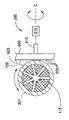
図5Aは、円柱状ローラ115上に配置された管状カバー128の処理表面301と接触しているコンディショナ500を有するコンディショニング装置200の別の一実施形態の上面図である。この実施形態では、コンディショナ500は、本体502の幾何学的中心のところで支持体部材510に連結されたディスク形状をした本体502を含む。この実施形態では、支持体部材510をアクスルとして適合させ、アクスルを、軸Cの周りに本体502を回転させるために利用するアクチュエータ515に連結する。この実施形態では、タンク105の内部容積が真空ポンプ330によってもたらされる負圧を封じ込めることを可能にするリッド(図示せず)とともに、タンク105を設けることができる。材料が管状カバー128の処理表面301から除去されるので、除去された材料、ならびに何らかの流体を、タンク105の内部から除去し、廃棄物システムまたは排除システムへと送ることができる。
FIG. 5A is a top view of another embodiment of a
図5Bは、図5Aの円柱状ローラ115およびコンディショナ500の断面図である。コンディショナ500は、外側表面503を含み、外側表面を、管状カバー128の処理表面301を削り落すために粗くすることができる。一実施形態では、外側表面503は、複数の盛り上がった形体505を含み、これを、ブリッスル、研磨剤粒子、構造的突起物、またはこれらの組み合わせとすることができる。
FIG. 5B is a cross-sectional view of the
この実施形態では、コンディショナ500を、円柱状ローラ115に対して回転するように適合させる。円柱状ローラ115に対する本体502の回転を容易にするために、コンディショナ500を支持体部材510に連結する。コンディショナ500を、円柱状ローラ115の回転に基づいて回転させるように適合させることができる、またはコンディショナ500が、円柱状ローラ115とは独立に回転させられる場合がある。一実施形態では、本体502を第4の軸Cと呼ぶことができる軸Cの周りで回転させるアクチュエータ515に、コンディショナ500を連結する。一実施形態では、本体502を回転させることができるが、円柱状ローラ115は静止している。別の一実施形態では、本体502を軸Cの周りに回転させることができるが、円柱状ローラ115は軸A”の周りを回転する。一態様では、回転軸A”は、回転軸Cに実質的に垂直である。
In this embodiment,
図6は、本明細書において説明したコンディショニング装置200を使用するコンディショニング方法600の一実施形態を示す流れ図である。610ところでは、処理表面301を有する円柱状ローラ115、120の一方または両方を、本明細書において説明したコンディショナ300、400または500などのコンディショナに接触するように設置する。620ところでは、相対的な運動を、処理表面301とコンディショナとの間に与える。相対的な運動を、コンディショナに対して円柱状ローラ115、120を回転させることによって、円柱状ローラ115、120に対してコンディショナを回転させることによって、またはこれらの組み合わせによって与えることができる。
FIG. 6 is a flow diagram illustrating one embodiment of a
図7は、本明細書において説明したようなスクラバボックス100を使用する基板処理方法700の一実施形態を示す流れ図である。710ところでは、基板を、2つの円柱状ローラ115、120の間の位置までタンク105へと搬送する。720ところでは、2つの円柱状ローラ115、120の各々を、円柱状ローラ115、120の処理表面301と基板の主要面との間の接触を容易にする第1の位置へと基板に向けて強く押し付ける。ステップ720中には、円柱状ローラ115、120および基板を、洗浄プロセスまたは研磨プロセスを実行するために相対的に回転させることができる。
FIG. 7 is a flow diagram illustrating one embodiment of a
730のところでは、基板の搬送を容易にするために、基板から離して円柱状ローラ115、120を間隔を空けて設置する第2の位置へと、円柱状ローラ115、120を移動させる。第2の位置は、円柱状ローラ115、120の各々の処理表面をコンディショニング装置と接触させることをやはり含み、コンディショニング装置を本明細書において説明したようなコンディショナ300、400、または500とすることができる。図6に説明したようなコンディショニング方法を、基板をタンク105の外へ搬送しながら実行することができる。もう1つの基板をタンク105中へと搬送し、方法を710のとろで始めて繰り返すことができるまで、コンディショニング方法を継続することができる。
At 730, in order to facilitate transport of the substrate, the
本明細書において説明したようなコンディショニング装置200の実施形態は、スクラバボックス100の円柱状ローラ115、120上で利用される管状カバー128の処理表面301の寿命を延長する。コンディショニング装置200の使用は、円柱状ローラ115、120をタンク105から取り除く必要がないように、円柱状ローラ115、120の処理表面301のその場洗浄を提供する。一実施形態では、新品または未使用の管状カバー128の処理表面301を、スクラバボックス100内で実行されるブレークインプロセスにおいてコンディショニングすることができる。ブレークインプロセスにおいてコンディショニング装置200を使用することは、ダミーウエハの必要性を最小にするまたは削除し、時間を節約する。加えて、基板搬送プロセス中での円柱状ローラ115、120の処理表面301のコンディショニングは、スクラバボックス100のスループットに影響を及ぼさない。本明細書において説明したようなコンディショニング装置200は、細孔を開かせることによって、ならびに処理表面301から凝集物および/または余剰な材料を除去することによって、管状カバー128の最適な処理表面301をやはり維持する。最適な処理表面301は、除去速度または洗浄効率を増加させ、管状カバー128の交換頻度を最小にする。したがって、スループットを最大にしながら、所有コストを最小にする。
Embodiments of the
上記は本発明の実施形態に向けられているが、本発明の別の実施形態およびさらなる実施形態を、本発明の基本的な範囲から乖離せずに考案することができる。 While the above is directed to embodiments of the invention, other and further embodiments of the invention may be devised without departing from the basic scope thereof.
Claims (12)
前記内部容積の外部に配置されたそれぞれの支持体部材に各端部で連結された1対の円柱状ローラであって、前記円柱状ローラの各々が、前記内部容積内に少なくとも部分的に配置され、それぞれの軸の周りを回転可能である、1対の円柱状ローラと、
前記円柱状ローラが互いに近接している第1の位置と前記円柱状ローラが互いに間隔を空けて離れている第2の位置との間で前記それぞれの円柱状ローラを移動させるために、前記円柱状ローラの各々に連結されたアクチュエータアセンブリと、
前記円柱状ローラの各々のためのコンディショニング装置であって、各コンディショニング装置が前記内部容積内に配置されたコンディショナを含み、前記円柱状ローラが前記第2の位置にあるときに、前記コンディショナが前記円柱状ローラの各々の外側表面と接触する、コンディショニング装置と
を備え、
前記コンディショナが、1つまたは複数の支持体部材によって前記タンクの側壁に回転可能に連結され、
前記1つまたは複数の支持体部材が、アクチュエータに連結され、
前記円柱状ローラが、第1の軸および第2の軸の周りを回転可能であって、前記第1の軸が、前記第2の軸とは異なり、前記第2の軸に平行であり、
前記アクチュエータが、前記第1の軸または前記第2の軸に実質垂直である第3の軸の周りに前記コンディショナを回転させる、
ブラシボックス。 A tank having an internal volume;
A pair of cylindrical rollers connected at each end to respective support members disposed outside the internal volume, each of the cylindrical rollers being at least partially disposed within the internal volume A pair of cylindrical rollers that are rotatable about respective axes;
In order to move the respective cylindrical rollers between a first position where the cylindrical rollers are close to each other and a second position where the cylindrical rollers are spaced apart from each other, An actuator assembly coupled to each of the columnar rollers;
A conditioning device for each of the cylindrical rollers, each conditioning device including a conditioner disposed within the internal volume, wherein the conditioner is in the second position when the cylindrical roller is in the second position. A conditioning device in contact with the outer surface of each of said cylindrical rollers,
The conditioner is rotatably coupled to the side wall of the tank by one or more support members ;
The one or more support members are coupled to an actuator;
The cylindrical roller is rotatable about a first axis and a second axis, the first axis being different from the second axis and parallel to the second axis;
The actuator rotates the conditioner about a third axis that is substantially perpendicular to the first axis or the second axis;
Brush box.
前記内部容積の外部に移動できるように配置されたそれぞれの支持部材に各端部で連結された1対の円柱状ローラであって、前記円柱状ローラの各々が、前記内部容積内に少なくとも部分的に配置され、それぞれの第1の軸の周りを回転可能である、1対の円柱状ローラと、
前記円柱状ローラが互いに近接している第1の位置と前記円柱状ローラが互いに間隔を空けて離れている第2の位置との間で前記それぞれの円柱状ローラを移動させるために、前記円柱状ローラの各々に連結されたアクチュエータアセンブリと、
前記ローラの各々のためのコンディショニング装置であって、各コンディショニング装置が前記内部容積内に配置されたコンディショナを含み、前記円柱状ローラが前記第2の位置にあるときに、各コンディショナが前記円柱状ローラの各々の外側表面と接触する、コンディショニング装置と
を備え、
各コンディショナが、1つまたは複数の支持体部材によって前記タンクの側壁に回転可能に連結され、
前記1つまたは複数の支持体部材が、アクチュエータに連結され、
前記アクチュエータが、第2の軸の周りに前記コンディショナを回転させ、前記第2の軸が、前記第1の軸とは異なる、
ブラシボックス。 A tank having an internal volume;
A pair of cylindrical rollers connected at respective ends to respective support members arranged to be movable outside the internal volume, each of the cylindrical rollers being at least partially within the internal volume A pair of cylindrical rollers that are arranged and rotatable about respective first axes;
In order to move the respective cylindrical rollers between a first position where the cylindrical rollers are close to each other and a second position where the cylindrical rollers are spaced apart from each other, An actuator assembly coupled to each of the columnar rollers;
A conditioning device for each of the rollers, wherein each conditioning device includes a conditioner disposed within the internal volume, wherein each conditioner is in the second position when the cylindrical roller is in the second position. contact with each of the outer surface of the cylindrical roller, Bei example a conditioning device,
Each conditioner is rotatably connected to the side wall of the tank by one or more support members;
The one or more support members are coupled to an actuator;
The actuator rotates the conditioner about a second axis, wherein the second axis is different from the first axis;
Brush box.
Applications Claiming Priority (3)
| Application Number | Priority Date | Filing Date | Title |
|---|---|---|---|
| US12/603,771 US8458843B2 (en) | 2009-10-22 | 2009-10-22 | Apparatus and methods for brush and pad conditioning |
| US12/603,771 | 2009-10-22 | ||
| PCT/US2010/046599 WO2011049671A1 (en) | 2009-10-22 | 2010-08-25 | Apparatus and methods for brush and pad conditioning |
Publications (3)
| Publication Number | Publication Date |
|---|---|
| JP2013508969A JP2013508969A (en) | 2013-03-07 |
| JP2013508969A5 JP2013508969A5 (en) | 2013-10-03 |
| JP5916617B2 true JP5916617B2 (en) | 2016-05-11 |
Family
ID=43897340
Family Applications (1)
| Application Number | Title | Priority Date | Filing Date |
|---|---|---|---|
| JP2012535203A Active JP5916617B2 (en) | 2009-10-22 | 2010-08-25 | Apparatus and method for brush conditioning and pad conditioning |
Country Status (4)
| Country | Link |
|---|---|
| US (3) | US8458843B2 (en) |
| JP (1) | JP5916617B2 (en) |
| TW (1) | TWI535529B (en) |
| WO (1) | WO2011049671A1 (en) |
Families Citing this family (17)
| Publication number | Priority date | Publication date | Assignee | Title |
|---|---|---|---|---|
| US8458843B2 (en) * | 2009-10-22 | 2013-06-11 | Applied Materials, Inc. | Apparatus and methods for brush and pad conditioning |
| US9646859B2 (en) * | 2010-04-30 | 2017-05-09 | Applied Materials, Inc. | Disk-brush cleaner module with fluid jet |
| US20130196572A1 (en) * | 2012-01-27 | 2013-08-01 | Sen-Hou Ko | Conditioning a pad in a cleaning module |
| CN102601736A (en) * | 2012-03-22 | 2012-07-25 | 珠海镇东有限公司 | Back pressure roller, leveling brush system and leveling brush method for plate polishing machine |
| CN104289470B (en) * | 2014-09-30 | 2017-11-14 | 重庆益新阳工贸有限公司 | A kind of brush formula spinning spindle supersonic wave cleaning machine |
| WO2018125821A1 (en) | 2016-12-30 | 2018-07-05 | Applied Materials, Inc. | Spray bar design for uniform liquid flow distribution on a substrate |
| US11923208B2 (en) * | 2017-05-19 | 2024-03-05 | Illinois Tool Works Inc. | Methods and apparatuses for chemical delivery for brush conditioning |
| US10410936B2 (en) * | 2017-05-19 | 2019-09-10 | Illinois Tool Works Inc. | Methods and apparatuses for effluent monitoring for brush conditioning |
| US10149135B1 (en) * | 2017-05-30 | 2018-12-04 | Illinois Tool Works Inc. | Methods and apparatuses for wireless communication with a brush |
| US10170343B1 (en) * | 2017-06-30 | 2019-01-01 | Taiwan Semiconductor Manufacturing Co., Ltd. | Post-CMP cleaning apparatus and method with brush self-cleaning function |
| CN107377441B (en) * | 2017-07-31 | 2021-01-22 | 京东方科技集团股份有限公司 | Cleaning device, cleaning equipment and cleaning method |
| CN108940939A (en) * | 2018-06-14 | 2018-12-07 | 东莞市光纳光电科技有限公司 | A kind of fingerprint recognition screen having self-cleaning ability |
| US11839907B2 (en) * | 2018-08-17 | 2023-12-12 | Taiwan Semiconductor Manufacturing Company, Ltd. | Breaking-in and cleaning method and apparatus for wafer-cleaning brush |
| NL2022059B1 (en) | 2018-11-23 | 2020-06-09 | Gerald Jg Belemans | Cleaning device for a pair of spectacles having bar-shaped cleaning elements. |
| JP7161418B2 (en) | 2019-01-30 | 2022-10-26 | 株式会社荏原製作所 | SUBSTRATE CLEANING APPARATUS, SUBSTRATE PROCESSING APPARATUS, SELF-CLEANING METHOD OF CLEANING MEMBER |
| JP7274883B2 (en) * | 2019-02-19 | 2023-05-17 | 株式会社荏原製作所 | Cleaning equipment for cleaning members and substrate processing equipment |
| JP7284514B2 (en) * | 2020-05-11 | 2023-05-31 | アピックヤマダ株式会社 | RESIN MOLDING DEVICE AND CLEANING METHOD |
Family Cites Families (22)
| Publication number | Priority date | Publication date | Assignee | Title |
|---|---|---|---|---|
| JPS4514156Y1 (en) * | 1965-12-29 | 1970-06-15 | ||
| US5775983A (en) * | 1995-05-01 | 1998-07-07 | Applied Materials, Inc. | Apparatus and method for conditioning a chemical mechanical polishing pad |
| US5639311A (en) * | 1995-06-07 | 1997-06-17 | International Business Machines Corporation | Method of cleaning brushes used in post CMP semiconductor wafer cleaning operations |
| US5745945A (en) * | 1996-06-28 | 1998-05-05 | International Business Machines Corporation | Brush conditioner for a semiconductor cleaning brush |
| JPH10323631A (en) * | 1997-05-23 | 1998-12-08 | Ebara Corp | Device for self-cleaning cleaning member |
| WO1999049995A1 (en) * | 1998-03-27 | 1999-10-07 | Rippey Corporation | A microcleaning process for sponge or porous polymeric products |
| US6158448A (en) * | 1998-03-27 | 2000-12-12 | Rippey Corporation | System for cleaning sponge or porous polymeric products |
| JP2001054765A (en) * | 1999-08-19 | 2001-02-27 | Dainippon Screen Mfg Co Ltd | Substrate cleaning device |
| US20020006767A1 (en) * | 1999-12-22 | 2002-01-17 | Applied Materials, Inc. | Ion exchange pad or brush and method of regenerating the same |
| AU2001251178A1 (en) * | 2000-03-31 | 2001-10-15 | Lam Research Corporation | Wafer preparation apparatus |
| US6328640B1 (en) * | 2000-03-31 | 2001-12-11 | Lam Research Corporation | Wafer preparation apparatus including rotatable wafer preparation assemblies |
| US20020115283A1 (en) * | 2001-02-20 | 2002-08-22 | Chartered Semiconductor Manufacturing Ltd. | Planarization by selective electro-dissolution |
| US6620029B2 (en) * | 2002-01-30 | 2003-09-16 | International Business Machines Corporation | Apparatus and method for front side chemical mechanical planarization (CMP) of semiconductor workpieces |
| JP2003311536A (en) * | 2002-04-23 | 2003-11-05 | Sony Corp | Polishing apparatus and method for polishing |
| US7377002B2 (en) | 2003-10-28 | 2008-05-27 | Applied Materials, Inc. | Scrubber box |
| KR20070119823A (en) | 2006-06-16 | 2007-12-21 | 삼성전자주식회사 | Apparatus for cleaning semiconductor wafer |
| KR20080024579A (en) | 2006-09-14 | 2008-03-19 | 삼성전자주식회사 | Pad conditioning apparatus in semiconductor device fabricating equipment |
| JP4934644B2 (en) * | 2007-06-25 | 2012-05-16 | 株式会社日立ハイテクノロジーズ | Disc cleaning mechanism and disc cleaning device |
| TW200914202A (en) * | 2007-09-19 | 2009-04-01 | Powerchip Semiconductor Corp | Polishing pad conditioner and method for conditioning polishing pad |
| US8795035B2 (en) * | 2008-06-26 | 2014-08-05 | Saint-Gobain Abrasives, Inc. | Chemical mechanical planarization pad conditioner and method of forming |
| US8458843B2 (en) * | 2009-10-22 | 2013-06-11 | Applied Materials, Inc. | Apparatus and methods for brush and pad conditioning |
| US20130196572A1 (en) * | 2012-01-27 | 2013-08-01 | Sen-Hou Ko | Conditioning a pad in a cleaning module |
-
2009
- 2009-10-22 US US12/603,771 patent/US8458843B2/en active Active
-
2010
- 2010-08-25 WO PCT/US2010/046599 patent/WO2011049671A1/en active Application Filing
- 2010-08-25 JP JP2012535203A patent/JP5916617B2/en active Active
- 2010-08-31 TW TW099129282A patent/TWI535529B/en active
-
2013
- 2013-05-17 US US13/897,008 patent/US8813293B2/en active Active
-
2014
- 2014-08-26 US US14/469,188 patent/US20140360976A1/en not_active Abandoned
Also Published As
| Publication number | Publication date |
|---|---|
| TWI535529B (en) | 2016-06-01 |
| US8813293B2 (en) | 2014-08-26 |
| US20110094537A1 (en) | 2011-04-28 |
| US8458843B2 (en) | 2013-06-11 |
| US20140360976A1 (en) | 2014-12-11 |
| WO2011049671A4 (en) | 2011-07-07 |
| JP2013508969A (en) | 2013-03-07 |
| TW201114548A (en) | 2011-05-01 |
| US20130247314A1 (en) | 2013-09-26 |
| WO2011049671A1 (en) | 2011-04-28 |
Similar Documents
| Publication | Publication Date | Title |
|---|---|---|
| JP5916617B2 (en) | Apparatus and method for brush conditioning and pad conditioning | |
| JP5279463B2 (en) | Single substrate processing apparatus and method | |
| JP4621055B2 (en) | Interface between the substrate and the meniscus and the handling method thereof | |
| US8382554B2 (en) | Substrate polishing apparatus and method of polishing substrate using the same | |
| US8382555B2 (en) | Substrate supporting unit, and apparatus and method for polishing substrate using the same | |
| EP0878831B1 (en) | Double side cleaning apparatus for semiconductor substrate | |
| US7052371B2 (en) | Vacuum-assisted pad conditioning system and method utilizing an apertured conditioning disk | |
| US20070151867A1 (en) | Apparatus and a method for electrochemical mechanical processing with fluid flow assist elements | |
| KR102211533B1 (en) | Polishing system with local area rate control | |
| KR20160024797A (en) | Buffing apparatus, and substrate processing apparatus | |
| KR20130066562A (en) | Tuning of polishing process in multi-carrier head per platen polishing station | |
| US10256120B2 (en) | Systems, methods and apparatus for post-chemical mechanical planarization substrate buff pre-cleaning | |
| CN111868889A (en) | Substrate cleaning apparatus and substrate cleaning method | |
| US10610994B2 (en) | Polishing system with local area rate control and oscillation mode | |
| US20090061743A1 (en) | Method of soft pad preparation to reduce removal rate ramp-up effect and to stabilize defect rate | |
| US10434623B2 (en) | Local area polishing system and polishing pad assemblies for a polishing system | |
| JP5675626B2 (en) | Stretching of polishing pad edge | |
| US20080020682A1 (en) | Method for conditioning a polishing pad | |
| CN116435220A (en) | Wafer cleaning device | |
| JP2000254856A (en) | Polishing device and polishing method | |
| WO2007111729A2 (en) | An apparatus and a method for electrochemical mechanical processing with fluid flow assist elements | |
| JP2004209644A (en) | Substrate polishing method and device | |
| KR20100019545A (en) | Single type substrate treating apparatus and method |
Legal Events
| Date | Code | Title | Description |
|---|---|---|---|
| A521 | Request for written amendment filed |
Free format text: JAPANESE INTERMEDIATE CODE: A523 Effective date: 20130814 |
|
| A621 | Written request for application examination |
Free format text: JAPANESE INTERMEDIATE CODE: A621 Effective date: 20130814 |
|
| A977 | Report on retrieval |
Free format text: JAPANESE INTERMEDIATE CODE: A971007 Effective date: 20140806 |
|
| A131 | Notification of reasons for refusal |
Free format text: JAPANESE INTERMEDIATE CODE: A131 Effective date: 20140812 |
|
| A521 | Request for written amendment filed |
Free format text: JAPANESE INTERMEDIATE CODE: A523 Effective date: 20141107 |
|
| A131 | Notification of reasons for refusal |
Free format text: JAPANESE INTERMEDIATE CODE: A131 Effective date: 20150512 |
|
| A521 | Request for written amendment filed |
Free format text: JAPANESE INTERMEDIATE CODE: A523 Effective date: 20150703 |
|
| TRDD | Decision of grant or rejection written | ||
| A01 | Written decision to grant a patent or to grant a registration (utility model) |
Free format text: JAPANESE INTERMEDIATE CODE: A01 Effective date: 20160308 |
|
| A61 | First payment of annual fees (during grant procedure) |
Free format text: JAPANESE INTERMEDIATE CODE: A61 Effective date: 20160405 |
|
| R150 | Certificate of patent or registration of utility model |
Ref document number: 5916617 Country of ref document: JP Free format text: JAPANESE INTERMEDIATE CODE: R150 |
|
| R250 | Receipt of annual fees |
Free format text: JAPANESE INTERMEDIATE CODE: R250 |
|
| R250 | Receipt of annual fees |
Free format text: JAPANESE INTERMEDIATE CODE: R250 |
|
| R250 | Receipt of annual fees |
Free format text: JAPANESE INTERMEDIATE CODE: R250 |
|
| R250 | Receipt of annual fees |
Free format text: JAPANESE INTERMEDIATE CODE: R250 |
|
| R250 | Receipt of annual fees |
Free format text: JAPANESE INTERMEDIATE CODE: R250 |