JP5914064B2 - Printing device - Google Patents
Printing device Download PDFInfo
- Publication number
- JP5914064B2 JP5914064B2 JP2012054653A JP2012054653A JP5914064B2 JP 5914064 B2 JP5914064 B2 JP 5914064B2 JP 2012054653 A JP2012054653 A JP 2012054653A JP 2012054653 A JP2012054653 A JP 2012054653A JP 5914064 B2 JP5914064 B2 JP 5914064B2
- Authority
- JP
- Japan
- Prior art keywords
- ink
- printing
- turntable
- controller
- Prior art date
- Legal status (The legal status is an assumption and is not a legal conclusion. Google has not performed a legal analysis and makes no representation as to the accuracy of the status listed.)
- Expired - Fee Related
Links
- 238000007639 printing Methods 0.000 title description 65
- 238000013459 approach Methods 0.000 claims description 2
- 239000000976 ink Substances 0.000 description 72
- 239000003086 colorant Substances 0.000 description 4
- 239000006229 carbon black Substances 0.000 description 3
- 238000010586 diagram Methods 0.000 description 3
- 230000000694 effects Effects 0.000 description 3
- 239000012744 reinforcing agent Substances 0.000 description 3
- 230000000452 restraining effect Effects 0.000 description 3
- 238000006243 chemical reaction Methods 0.000 description 2
- 239000011888 foil Substances 0.000 description 2
- 230000006870 function Effects 0.000 description 2
- 238000000034 method Methods 0.000 description 2
- 239000003973 paint Substances 0.000 description 2
- 238000009792 diffusion process Methods 0.000 description 1
- 238000007599 discharging Methods 0.000 description 1
- 239000000428 dust Substances 0.000 description 1
- 230000004886 head movement Effects 0.000 description 1
- 238000007641 inkjet printing Methods 0.000 description 1
- 238000012986 modification Methods 0.000 description 1
- 230000004048 modification Effects 0.000 description 1
- 230000002093 peripheral effect Effects 0.000 description 1
- 230000004044 response Effects 0.000 description 1
- 239000007921 spray Substances 0.000 description 1
- XLYOFNOQVPJJNP-UHFFFAOYSA-N water Substances O XLYOFNOQVPJJNP-UHFFFAOYSA-N 0.000 description 1
Images


Classifications
-
- B—PERFORMING OPERATIONS; TRANSPORTING
- B05—SPRAYING OR ATOMISING IN GENERAL; APPLYING FLUENT MATERIALS TO SURFACES, IN GENERAL
- B05C—APPARATUS FOR APPLYING FLUENT MATERIALS TO SURFACES, IN GENERAL
- B05C5/00—Apparatus in which liquid or other fluent material is projected, poured or allowed to flow on to the surface of the work
- B05C5/02—Apparatus in which liquid or other fluent material is projected, poured or allowed to flow on to the surface of the work the liquid or other fluent material being discharged through an outlet orifice by pressure, e.g. from an outlet device in contact or almost in contact, with the work
- B05C5/0208—Apparatus in which liquid or other fluent material is projected, poured or allowed to flow on to the surface of the work the liquid or other fluent material being discharged through an outlet orifice by pressure, e.g. from an outlet device in contact or almost in contact, with the work for applying liquid or other fluent material to separate articles
- B05C5/0212—Apparatus in which liquid or other fluent material is projected, poured or allowed to flow on to the surface of the work the liquid or other fluent material being discharged through an outlet orifice by pressure, e.g. from an outlet device in contact or almost in contact, with the work for applying liquid or other fluent material to separate articles only at particular parts of the articles
- B05C5/0216—Apparatus in which liquid or other fluent material is projected, poured or allowed to flow on to the surface of the work the liquid or other fluent material being discharged through an outlet orifice by pressure, e.g. from an outlet device in contact or almost in contact, with the work for applying liquid or other fluent material to separate articles only at particular parts of the articles by relative movement of article and outlet according to a predetermined path
-
- B—PERFORMING OPERATIONS; TRANSPORTING
- B41—PRINTING; LINING MACHINES; TYPEWRITERS; STAMPS
- B41J—TYPEWRITERS; SELECTIVE PRINTING MECHANISMS, i.e. MECHANISMS PRINTING OTHERWISE THAN FROM A FORME; CORRECTION OF TYPOGRAPHICAL ERRORS
- B41J3/00—Typewriters or selective printing or marking mechanisms characterised by the purpose for which they are constructed
- B41J3/407—Typewriters or selective printing or marking mechanisms characterised by the purpose for which they are constructed for marking on special material
- B41J3/4073—Printing on three-dimensional objects not being in sheet or web form, e.g. spherical or cubic objects
-
- B—PERFORMING OPERATIONS; TRANSPORTING
- B05—SPRAYING OR ATOMISING IN GENERAL; APPLYING FLUENT MATERIALS TO SURFACES, IN GENERAL
- B05B—SPRAYING APPARATUS; ATOMISING APPARATUS; NOZZLES
- B05B13/00—Machines or plants for applying liquids or other fluent materials to surfaces of objects or other work by spraying, not covered by groups B05B1/00 - B05B11/00
- B05B13/02—Means for supporting work; Arrangement or mounting of spray heads; Adaptation or arrangement of means for feeding work
- B05B13/0221—Means for supporting work; Arrangement or mounting of spray heads; Adaptation or arrangement of means for feeding work characterised by the means for moving or conveying the objects or other work, e.g. conveyor belts
- B05B13/0228—Means for supporting work; Arrangement or mounting of spray heads; Adaptation or arrangement of means for feeding work characterised by the means for moving or conveying the objects or other work, e.g. conveyor belts the movement of the objects being rotative
-
- B—PERFORMING OPERATIONS; TRANSPORTING
- B41—PRINTING; LINING MACHINES; TYPEWRITERS; STAMPS
- B41J—TYPEWRITERS; SELECTIVE PRINTING MECHANISMS, i.e. MECHANISMS PRINTING OTHERWISE THAN FROM A FORME; CORRECTION OF TYPOGRAPHICAL ERRORS
- B41J2/00—Typewriters or selective printing mechanisms characterised by the printing or marking process for which they are designed
- B41J2/005—Typewriters or selective printing mechanisms characterised by the printing or marking process for which they are designed characterised by bringing liquid or particles selectively into contact with a printing material
- B41J2/01—Ink jet
- B41J2/015—Ink jet characterised by the jet generation process
- B41J2/04—Ink jet characterised by the jet generation process generating single droplets or particles on demand
- B41J2/045—Ink jet characterised by the jet generation process generating single droplets or particles on demand by pressure, e.g. electromechanical transducers
- B41J2/04501—Control methods or devices therefor, e.g. driver circuits, control circuits
- B41J2/04503—Control methods or devices therefor, e.g. driver circuits, control circuits aiming at compensating carriage speed
-
- B—PERFORMING OPERATIONS; TRANSPORTING
- B41—PRINTING; LINING MACHINES; TYPEWRITERS; STAMPS
- B41J—TYPEWRITERS; SELECTIVE PRINTING MECHANISMS, i.e. MECHANISMS PRINTING OTHERWISE THAN FROM A FORME; CORRECTION OF TYPOGRAPHICAL ERRORS
- B41J2/00—Typewriters or selective printing mechanisms characterised by the printing or marking process for which they are designed
- B41J2/005—Typewriters or selective printing mechanisms characterised by the printing or marking process for which they are designed characterised by bringing liquid or particles selectively into contact with a printing material
- B41J2/01—Ink jet
- B41J2/21—Ink jet for multi-colour printing
- B41J2/2107—Ink jet for multi-colour printing characterised by the ink properties
- B41J2/2114—Ejecting transparent or white coloured liquids, e.g. processing liquids
- B41J2/2117—Ejecting white liquids
-
- B—PERFORMING OPERATIONS; TRANSPORTING
- B60—VEHICLES IN GENERAL
- B60C—VEHICLE TYRES; TYRE INFLATION; TYRE CHANGING; CONNECTING VALVES TO INFLATABLE ELASTIC BODIES IN GENERAL; DEVICES OR ARRANGEMENTS RELATED TO TYRES
- B60C13/00—Tyre sidewalls; Protecting, decorating, marking, or the like, thereof
- B60C13/001—Decorating, marking or the like
Description
本発明はプリント装置に係り、特に、タイヤの側面等のドーナッツ状の面に所望の絵柄や文字をプリントするプリント装置に関する。 The present invention relates to a printing apparatus, and more particularly to a printing apparatus that prints a desired pattern or character on a donut-shaped surface such as a side surface of a tire.
自動車のタイヤはゴムの補強剤としてカーボンブラックが配合されていることから黒いものが殆どであるが、黒だけでなくカラフルなカラータイヤの要望もあったことからカーボンブラックを使用しない補強剤も開発され、種々の色のタイヤを製造することができるようになった。しかし、コスト面や性能面でカーボンブラックを越える補強剤がないことからカラータイヤが普及しない要因となっている。 Automobile tires are mostly black because carbon black is blended as a rubber reinforcing agent, but because there was a demand for not only black but also colorful color tires, a reinforcing agent that does not use carbon black was also developed. Thus, tires of various colors can be manufactured. However, since there is no reinforcing agent that exceeds carbon black in terms of cost and performance, it is a factor that prevents the use of color tires.
そのため、タイヤのゴム自体をカラーにするのではなく、黒いタイヤにプリントによってカラフルな色を付する方法や装置が提案されている。例えば、特許文献1はタイヤの側面にフルカラーの印刷を施すための装置及び方法を開示している。その装置としては、具体的には、搬入部、反転部、印刷部、搬出部及びこれらを制御する制御部及び印刷部の印刷動作を制御する印刷制御部からなり、印刷部ではタイヤの印刷面を清浄及びプライマー塗布を行い、次いでIJP(インクジェット)印刷装置で印刷を行い、次いで、各印刷の度毎にUVランプUの照射によりインクの硬化・定着を行うものであり、印刷時には識別カメラによって予め付されたタイヤの印刷原点マークを認識し、リングエンコーダが発生する回転パルスの所定のパルス数目を印刷開始位置とし、各IJPヘッドに印刷開始信号を送信して各IJPヘッドからインキを噴射することにより、タイヤの所定の印刷位置に所定の印刷パターンを印刷するというものである。
Therefore, there has been proposed a method and an apparatus for applying a colorful color to a black tire by printing, instead of making the rubber of the tire itself a color. For example,
しかし、特許文献1のインクジェット印刷装置は、印刷の制御に識別カメラを用いて印刷原点マークの認識や原点信号の発生等を行っていることからカメラのレンズに汚れやごみ等が付着した場合に正しい印刷ができなくなる恐れがあり、また、部品点数も多く制御が複雑になるという問題があった。
また、搬入部、反転部、印刷部、搬出部を備え、各部は搬送チェーンコンベアで連結されて構成されており、装置が大型化するという問題があった。
さらに、印刷時には上抑えロールによってタイヤの側面を強制的に抑え込んで平坦性を確保した上で印刷を行うような構成とされているがタイヤの側面を抑え付けて印刷した印刷面が上抑えロールによる負荷が解放されて元の状態に復元した後では印刷に歪みが生じることが懸念される。
However, the inkjet printing apparatus of
Moreover, a carrying-in part, a reversing part, a printing part, and a carrying-out part are provided, and each part is configured by being connected by a transport chain conveyor, which causes a problem that the apparatus becomes large.
Furthermore, when printing, the side surface of the tire is forcibly suppressed by a top restraining roll to ensure flatness and printing is performed, but the printed surface printed by restraining the tire side surface is the top restraining roll. There is a concern that the printing may be distorted after the load caused by is released and restored to the original state.
そこで、本発明の目的は、かかる従来の装置の欠点を改良し、簡単な構成でありながらタイヤの側面等のドーナッツ状の面に正確かつ美しい絵柄や文字をフルカラーでプリントすることが可能なプリント装置を提供することにある。 Therefore, an object of the present invention is to improve the drawbacks of the conventional apparatus, and can print an accurate and beautiful pattern and characters in full color on a donut-shaped surface such as a side surface of a tire with a simple configuration. To provide an apparatus.
上記目的を達成するため、請求項1に記載の本発明は、ドーナッツ状の被プリント面を上方に向けて載置したプリント対象物を回転させる回転台と、インクを吐出するノズルを複数備え、回転台に載置されたプリント対象物の被プリント面の回転の外側から回転中心に向かって移動可能なプリントヘッドと、プリントヘッドの移動速度、回転台の回転速度及び複数のノズルからのインクの吐出を制御するコントローラとを備え、コントローラは、回転台に載置したプリント対象物を回転させつつ、プリントヘッドを連続的に移動させながら複数のノズルからインクを吐出させると共に、回転中心に近づくにしたがって回転速度及びプリントヘッドの移動速度を速くすることにより被プリント面とプリントヘッドの相対速度が一定になるようにして被プリント面に螺旋状にプリントするように制御することを特徴とする。
In order to achieve the above object, the present invention described in
本発明に係るタイヤ用プリント装置によれば、プリントヘッドの移動を停止させることなく連続してインクを吐出しながらプリントすることができるので短時間にプリントを行うことができるという効果がある。
また、簡単な構成でありながらタイヤの側面等のドーナッツ状の面に所望の絵柄や文字をフルカラーでプリントすることができるという効果がある。
According to the tire printing apparatus of the present invention, printing can be performed in a short time because printing can be performed while ejecting ink continuously without stopping the movement of the print head.
In addition, there is an effect that a desired pattern and characters can be printed in full color on a donut-shaped surface such as a side surface of a tire with a simple configuration.
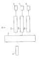
以下、本発明に係るプリント装置について好ましい一実施形態に基づき図面を参照しつつ詳細に説明する。図1(a)は本発明に係るプリント装置の概要を示す側面図、(b)はその平面図である。 Hereinafter, a printing apparatus according to the present invention will be described in detail based on a preferred embodiment with reference to the drawings. FIG. 1A is a side view showing an outline of a printing apparatus according to the present invention, and FIG. 1B is a plan view thereof.
[プリント装置の構成]
図示されたプリント装置1は、概略として、プリント対象物の被プリント面にフルカラーのプリントを行うプリント部10と、プリント部10の後述するインクタンク21a〜21fに加圧エアを送るエアコンプレッサ40と、プリント対象物へのプリントを制御するプリントのコントローラ50を備えて構成されている。
[Configuration of printing device]
The illustrated
プリント部10は、プリントを行うための各種の機器によって形成されたプリント本体20と、プリント対象物を回転可能に載置するテーブル部30を備えて構成されており、プリント本体20及びテーブル部30は架台11に配置されている。
The
プリント本体20は、各色別のインク(塗料)をそれぞれ収容する6つのインクタンク21a〜21fと、各色のインクタンク21a〜21fのそれぞれから送られたインクをプリント対象物の被プリント面に吐出するためのノズル23a〜23fを所定の配列で配置したプリントヘッド23と、プリントヘッド23をテーブル部30に載置されたプリント対象物の被プリント面の近傍へ位置させると共にプリント時には被プリント面の回転の外側から回転中心に向かって移動させる案内装置24を備えている。また、プリント本体20は、エアコンプレッサ40から送られてくる加圧エアの圧力を調整してインクタンク21a〜21fのそれぞれに送るエアレギュレータ26と、案内装置24に移動可能に取り付けられたプリントヘッド23のプリント対象物の被プリント面との高さ位置を調整するノズル上下移動機構29を備えている。
The print
インクタンク21は、上述のように、6つのインクタンク21a〜21fを備えて構成されており、インクタンク21aには白(W1)のインクが収容され、インクタンク21bにも白(W2)のインクが収容され、インクタンク21cには黒(K)のインクが収容され、インクタンク21dにはシアン(C)のインクが収容され、インクタンク21eにはマゼンタ(M)のインクが収容され、インクタンク21fにはイエロー(Y)のインクが収容されている。尚、インクタンク21a,21bにはそれぞれ白(W1及びW2)のインクが充填されているが白(W)はインクタンク21aのみとし、インクタンク21b〜21eはそれぞれ黒(K)、シアン(C)、マゼンタ(M)、イエロー(Y)とし、インクタンク21fは予備とすることもできる。また、インクタンク21a〜21fの数はこれに限定されるものではなく、適宜の数を配置してもよい。また、各色のインクは環境に優しい水性インクが利用される。
As described above, the ink tank 21 includes the six
そして、各インクタンク21a〜21fのそれぞれはインク供給チューブを介して各スプレーガンのノズル23a〜23fと接続されている。すなわち、インクタンク21a(W1)にはノズル23aが接続され、インクタンク21b(W2)にはノズル23bが接続され、インクタンク21c(K)にはノズル23cが接続され、インクタンク21d(C)にはノズル23dが接続され、インクタンク21e(M)にはノズル23eが接続され、インクタンク21fにはノズル23f(Y)が接続されている。尚、図示された各色のノズル23a〜23fは各インクタンク21a〜21fに対して1つとされているが、これに限らず各色のインクタンク21a〜21fに対してノズル23a〜23fを複数、例えば5個ずつ設けることも可能である。
Each of the
ノズル上下移動機構29は、プリントヘッド23の高さ位置の調整を行うための機構である。ノズル上下移動機構29は、図2に示すように、ネジ溝を備えたネジ部29bに、このネジ部29bの回転によって上下移動するナット部29cが配置されており、ネジ部29bの上端にはハンドル29aを有して構成されている。そして、ナット部29cには案内装置24が取り付けられている。これにより、ハンドル29aを回すことによって案内装置24の高さ位置を調整することによって案内装置24に取り付けられたプリントヘッド23の高さを調整することが可能となる。尚、ネジ部29bは架台11上に立設された支持台28に回転可能に支持されて立設されている。
The nozzle
案内装置24は、直線状のレールの上を往復走行する図示しない走行ブロックを備えた直動装置によって構成されており、この走行ブロックにプリントヘッド23が取り付けられて構成されている。また、走行ブロックは水平軸移動モータ25によってレール上を走行するように構成されている。そして、水平軸移動モータ25は、後述するコントローラ50からの制御信号を受けて図示しない走行ブロックを移動させることによりテーブル部30に載置されたプリント対象物の被プリント面への所定位置へプリントヘッド23を案内してプリントを行うようになっている。また、案内装置24は、後述するテーブル部30にプリント対象物を載置するための作業を阻害することがないよう、ナット部29cを回転させる等して適宜の場所に待避させることができるようになっている。
The
テーブル部30は、プリント対象物を回転可能に載置する載置台であり、概略として、プリント対象物を載置して回転するターンテーブル33と、プリント対象物の回転中心を位置決めする位置決めガイド31と、位置決めガイド31を中心にしてターンテーブル33を回転させる回転軸モータ35(図2参照)とを備えて構成されている。そして、ターンテーブル33の表面には回転時にプリント対象物がターンテーブル33と共に回転するよう滑り止め部材36、例えば、板状のゴム等が配設されている。本実施形態ではプリント対象物として自動車のタイヤTを示している。すなわち、タイヤTはホイルを取り付けた状態でホイルの中心に設けられている開口部を位置決めガイド31へ挿入し、ホイルの裏面側がターンテーブル33に回転可能に保持されるようにしてタイヤTのプリントを施すべき面側を上にして載置する。このように、単に位置決めガイド31にタイヤTのホイルの開口部を挿入するようにして配置することでタイヤTの中心をターンテーブル33の回転中心に簡単に位置合わせすることができるようになっている。また、ターンテーブル33にゴム等の滑り止め部材36を配設したことでターンテーブル33にタイヤTを載置するだけで安定して回転させることができるのでタイヤTの取り付け取り外しの作業性が向上する。そして、回転軸モータ35は後述するコントローラ50からの制御信号を受けてターンテーブル33上に載置されたタイヤTを回転させる。
The
エアコンプレッサ40は、図4に示すように、各色のインクが充填されたインクタンク21a〜21fのそれぞれに加圧エアの供給を行う加圧エアの供給装置である。このエアコンプレッサ40から供給された加圧エアは、エアレギュレータ26によって所定の圧力に調整された後、各インクタンク21a〜21fへ供給され、各ノズル23a〜23fからインクを加圧状態で吐出してプリントを行う。具体的には、図4に示すように、ノズル23aの内部には電磁アクチュエータ231aと、電磁アクチュエータ231aによって開閉動作を行うニードル弁232aが配置されおり、電磁アクチュエータ231aはコントローラ50内に設けられた後述するノズル駆動コントローラ53aによってその動作が制御されるようになっている。これにより、ノズル23aからのインク(W)の吐出の制御が行われ、タイヤTの被プリント面へのプリントが行われる。ノズル23aからのインク(W)の吐出は、その吐出量の多少による色の濃淡についても後述するコントローラ50によって制御が行われるようになっている。尚、図4ではノズル23aについて示しているが他のノズル23b〜23fも同様の構造となっている。
As shown in FIG. 4, the
ここで、プリントヘッド23のノズル23a〜23fは、最初に白(W1及びW2)のインクからペイントが開始されるようにして配置されている。具体的には、図1(b)及び図2に示すように、最も位置決めガイド31に近い側に白(W)のインクをプリントするためのノズル23aが配置されている。これにより、初めにノズル23a,23bによって白(W1及びW2)のインクをプリントした後、プリントヘッド23の前進によって次に配置された黒(K)のインクをプリントするノズル23cが白(W)のインクがプリントされた部分に位置することとなる。白(W1及びW2)を最初にプリントするのは各色のインクの色を正しく発色させるためである。従って、白(W1及びW2)が最初であれば、その他の色の順番は特に限定されることはない。
Here, the
次に、コントローラ50は、図示しない中央制御装置(CPU)及びメモリ等の記憶装置からなる演算装置51を備えて構成されており、演算装置51の記憶装置に記録されたプログラムをCPUによって処理することにより各種の動作を行ういわゆるコンピュータの機能を有している。コントローラ50には、図3に示すように、ノズル23a〜23fからの各インクの吐出の制御を行うノズル駆動コントローラ53aと、水平軸移動モータ25の回転を制御することによってプリントヘッド23の水平方向への移動の制御を行う水平移動軸モータコントローラ53bと、回転軸モータ35を制御してターンテーブル33上に載置されたプリント対象物(タイヤT)の回転数を制御する回転軸モータコントローラ53cが設けられており、図示しない記憶装置に記録されたプログラムによって実行されることでそれらの機能が発揮されるようになっている。尚、CPUやメモリ等の記憶装置等の機器類やその具体的な構造等については公知であり、その詳しい説明は省略する。
Next, the
また、コントローラ50は、プリント部10及びテーブル部30の動作の設定を入力するための入力部61を備えており、それらはキーボードの他、タッチパネル62によって提供されている。また、プリント装置1の動作状況を示すための表示部63を備えている。尚、タイヤTの被プリント面にプリントする絵柄や文字等のデータは入力部61のインターフェイスを介してコントローラ50に読み込まれ、タッチパネル62からの入力指示に基づいてコントローラ50のノズル駆動コントローラ53a、水平移動軸モータコントローラ53b、回転軸モータコントローラ53cの動作が制御されてプリントが行われる。
The
次に、コントローラ50によるプリント制御について説明する。図5(a)に示すように、本発明に係るプリント装置1は、プリント対象物であるタイヤTを回転させると同時に、プリントヘッド23を外周側から回転中心である位置決めガイド31方向に連続移動させることにより、タイヤTの被プリント面に螺旋状にプリントを行うものである。そして、この螺旋状のプリントは、ターンテーブル33の回転速度とプリントヘッド23の移動速度さらにはノズル23a〜23fからのインクの吐出位置や吐出量等を水平移動軸モータコントローラ53bと回転軸モータコントローラ53cさらにはノズル駆動コントローラ53aを互いにリンクさせながら制御を行なうことによって行われる。
Next, print control by the
具体的には、回転するタイヤTの円心を座標(0,0)の原点と定義する。そして、プリントする画像データの中心位置は、タイヤTの中心と定義する。プリントが行われている際は、タイヤTがターンテーブル33上に固定され、プリントヘッド23が回転していると解釈してノズル23a〜23fの位置を回転中心からの座標値で表現する。ノズル23a〜23fからインクを吐出すべき位置をドット位置と称し、その位置を一定回転角毎または一定距離毎に決定する。次いで、このドット位置に対応する画像データの画素値を、そのドット位置の表現するデータ値とする。各ノズル23a〜23fのドット位置に対応する画像データ上の座標は、タイヤTの回転角とノズル23a〜23fの移動量から、回転行列式にて直交座標から極座標に変換して求める。
Specifically, the circle center of the rotating tire T is defined as the origin of the coordinates (0, 0). The center position of the image data to be printed is defined as the center of the tire T. When printing is performed, the tire T is fixed on the

次いで、回転行列式による変換によって求めた画像データの座標位置における画素データをコントローラ50によってサンプリングする。この時に座標値が整数にならない場合は、コントローラ50は画像処理の補間を行ない、あるいは、サンプリングした画素データの濃度値からノズル23a〜23fから吐出すべきインクの量を算出する際に1ドットで表現出来なかった誤差分については周辺ドットに拡散する誤差拡散方式を使用する等して画像データを適宜に修正してプリントを行う。このようなプリントにおける一連の動作はコントローラ50の演算装置51に設けられた記憶装置に記録保存されたプログラムに基づくノズル駆動コントローラ53a、水平移動軸モータコントローラ53b及び回転軸モータコントローラ53cによって実行される。このようにしてタイヤTの被プリント面にプリントを行う。
Next, the
プリント時におけるコントローラ50による各部の制御は、水平移動軸モータコントローラ53bと回転軸モータコントローラ53cさらにはノズル駆動コントローラ53aを互いにリンクさせることにより、例えば、ターンテーブル33の回転速度とプリントヘッド23が回転中心に近づくほど速くすることにより螺旋軌道上のプリントヘッド23とタイヤTの相対移動速度が均一になるようにしてプリントしたり、ターンテーブル33の回転数は一定に保持しながらプリントヘッドの移動速度を速めたり、あるいは、ノズル23a〜23fからの各インクの吐出量及び吐出速度を適宜に調整することによって行われる。
Control of each part by the
[プリンタ装置の動作]
次に、プリント装置1の動作について説明する。
初めに、プリント対象物の被プリント面にプリントすべき絵柄や文字等の画像データを入力部61を介してコントローラ50の演算装置51に記録保存する。そして、プリントを行うべきプリント対象物(タイヤT)の被プリント面を上にしてテーブル部30のターンテーブル33に載置する。このとき位置決めガイド31によってタイヤTはその中心がターンテーブル33の回転中心に位置されると共に、ターンテーブル33の表面に設けられた滑り止め部材36によってしっかりと保持される。そして、ハンドル29aを操作してプリントヘッド23を所定の高さ位置に合わせる。次いで、コントローラ50のタッチパネル62の図示しない操作ボタンを押してプリントを開始する。タッチパネル62上のプリント開始ボタンが押されると水平移動軸モータコントローラ53bと回転軸モータコントローラ53cによってそれぞれ水平軸移動モータ25及び回転軸モータ35が作動を開始してプリントを開始する。尚、ターンテーブル33の回転速度はおおよそ1〜2回転/秒であるが、プリントする絵柄や文字に応じて適宜の速度で回転させることができる。
[Printer operation]
Next, the operation of the
First, image data such as a pattern and characters to be printed on the print surface of the print object is recorded and stored in the
プリントヘッド23が被プリント面へのプリント開始位置に位置すると最初にノズル23aから白(W1)のインクが吐出されてプリントが開始される。プリントヘッド23は回転中心方向に移動しつつターンテーブル33が回転しているので被プリント面に対するノズル23aからの白(W1)のインクによるプリントは螺旋状に行われることになる。そして、プリントヘッド23のターンテーブル33の回転によってノズル23bがノズル23aのプリント開始位置に位置するとノズル23bからのプリントが開始されて白(W2)のインクがプリントされる。そして、ノズル23aは新たな被プリント面へ白(W1)のインクでプリントを行う。さらにプリントヘッド23が回転中心方向に移動しつつターンテーブル33が回転してノズル23cがノズル23a及びノズル23bのプリント開始位置に位置すると今度はノズル23cからのプリントが開始されて白(W1)及び白(W2)がプリントされた場所に黒(K)のインクがプリントされる。この動作を順次繰り返しながらプリントヘッド23はタイヤTの被プリント面へ螺旋状にプリントが行われる。
When the
このプリントヘッド23によるプリントは、コントローラ50のノズル駆動コントローラ53aによって画像データに基づき各ノズル23a〜23fからインクを吐出すべきドット位置を一定回転角毎または一定距離毎に決定し、このドット位置に対応する画像データの画素値をそのドット位置の表現するデータ値とし、回転行列式(数1)にて変換した座標位置に基づいて行われる。そして、コントローラ50の水平移動軸モータコントローラ53b及び回転軸モータコントローラ53cはプリントヘッド23とターンテーブル33の回転速度とを制御して演算装置51に記憶された画像データに基づく絵柄や文字等を被プリント面に描く。
In the printing by the
また、回転行列式(数1)による変換の際に座標値が整数にならない場合やサンプリングした画素データの濃度値からノズル23a〜23fから吐出すべきインクの量を算出する際に1ドットで表現出来なかった誤差分等については、ノズル駆動コントローラ53aによって各ノズル23a〜23fから吐出するインクの量を制御することで適宜の画像処理が行われる。
In addition, when the coordinate value does not become an integer upon conversion by the rotation determinant (Equation 1), or when calculating the amount of ink to be ejected from the
以上の動作によりプリント装置1はプリント対象物であるタイヤTの側面である被プリント面に所定の絵柄や文字のプリントを行う。
With the above operation, the
[実施形態の効果]
以上のように、本実施形態によるプリント装置によれば、プリントヘッドの移動を停止させることなく連続してインクを吐出しながらプリントすることができるので短時間にプリントを行うことができるという効果がある。また、従来に比べて簡単な構成でありながらタイヤの側面等のドーナッツ状の面に所望の絵柄や文字をフルカラーでプリントすることができるという効果がある。
[Effect of the embodiment]
As described above, according to the printing apparatus according to the present embodiment, since printing can be performed while ink is continuously discharged without stopping the movement of the print head, it is possible to perform printing in a short time. is there. In addition, there is an effect that a desired pattern and characters can be printed in full color on a donut-shaped surface such as a side surface of a tire, although the configuration is simpler than in the past.
以上のように、本発明の好ましい実施形態について詳述したが、本発明は詳述した特定の実施形態に限定されるものではなく、特許請求の範囲に記載された本発明の要旨の範囲内において、種々の変形・変更が可能であることはいうまでもない。プリント対象物としてタイヤTを例にして説明したが、これに限定されるものではなく、リング状、円盤状のものや適宜の形状を備えたプリント対象物にプリントを行うことができる。 As described above, the preferred embodiments of the present invention have been described in detail, but the present invention is not limited to the specific embodiments described in detail, and is within the scope of the gist of the present invention described in the claims. Needless to say, various modifications and changes are possible. Although the tire T has been described as an example of the print object, the present invention is not limited to this, and printing can be performed on a print object having a ring shape, a disk shape, or an appropriate shape.
1 プリント装置
10 プリント部
11 架台
20 プリント本体
21a〜21f インクタンク
23 プリントヘッド
23a〜23f ノズル
24 案内装置
25 水平軸移動モータ
26 エアレギュレータ
28 支持台
29 ノズル上下移動機構
29a ハンドル
29b ネジ部
29c ナット部
30 テーブル部
31 位置決めガイド
33 ターンテーブル33
35 回転軸モータ
36 滑り止め部材
40 エアコンプレッサ
50 コントローラ
51 演算装置
53a ノズル駆動コントローラ
53b 水平移動軸モータコントローラ
53c 回転軸モータコントローラ
61 入力部
62 タッチパネル
63 表示部
T タイヤ
DESCRIPTION OF
35
Claims (1)
インクを吐出するノズルを複数備え、前記回転台に載置された前記プリント対象物の被プリント面の回転の外側から回転中心に向かって移動可能なプリントヘッドと、
前記プリントヘッドの移動速度、前記回転台の回転速度及び前記複数のノズルからのインクの吐出を制御するコントローラと、
を備え、
前記コントローラは、前記回転台に載置した前記プリント対象物を回転させつつ、前記プリントヘッドを連続的に移動させながら前記複数のノズルからインクを吐出させると共に、回転中心に近づくにしたがって前記回転速度及び前記プリントヘッドの移動速度を速くすることにより前記被プリント面と前記プリントヘッドの相対速度が一定になるようにして前記被プリント面に螺旋状にプリントするように制御することを特徴とするプリント装置。 A turntable for rotating a print object placed with the donut-shaped printed surface facing upward;
A plurality of nozzles that eject ink, and a print head that is movable from the outside of the print surface of the print object placed on the turntable toward the center of rotation;
A controller that controls the movement speed of the print head, the rotation speed of the turntable, and the ejection of ink from the plurality of nozzles;
With
The controller discharges ink from the plurality of nozzles while continuously moving the print head while rotating the print object placed on the turntable, and the rotation speed as it approaches the rotation center. And controlling the print surface to be spirally printed on the print surface so that the relative speed between the print surface and the print head becomes constant by increasing the moving speed of the print head. apparatus.
Priority Applications (3)
| Application Number | Priority Date | Filing Date | Title |
|---|---|---|---|
| JP2012054653A JP5914064B2 (en) | 2012-03-12 | 2012-03-12 | Printing device |
| EP13158327.0A EP2638979B1 (en) | 2012-03-12 | 2013-03-08 | Printing device |
| US13/797,047 US8801131B2 (en) | 2012-03-12 | 2013-03-12 | Printing device |
Applications Claiming Priority (1)
| Application Number | Priority Date | Filing Date | Title |
|---|---|---|---|
| JP2012054653A JP5914064B2 (en) | 2012-03-12 | 2012-03-12 | Printing device |
Publications (3)
| Publication Number | Publication Date |
|---|---|
| JP2013188647A JP2013188647A (en) | 2013-09-26 |
| JP2013188647A5 JP2013188647A5 (en) | 2014-09-25 |
| JP5914064B2 true JP5914064B2 (en) | 2016-05-11 |
Family
ID=47912962
Family Applications (1)
| Application Number | Title | Priority Date | Filing Date |
|---|---|---|---|
| JP2012054653A Expired - Fee Related JP5914064B2 (en) | 2012-03-12 | 2012-03-12 | Printing device |
Country Status (3)
| Country | Link |
|---|---|
| US (1) | US8801131B2 (en) |
| EP (1) | EP2638979B1 (en) |
| JP (1) | JP5914064B2 (en) |
Families Citing this family (9)
| Publication number | Priority date | Publication date | Assignee | Title |
|---|---|---|---|---|
| KR101537010B1 (en) * | 2013-11-29 | 2015-07-23 | (주)퍼시픽패키지 | A Packing Materials Edge Printing Unit and Pack Manufacturied Thereof |
| WO2015116239A1 (en) * | 2014-01-30 | 2015-08-06 | Apv Nano Fusing, Llc | Tire component marking apparatus and method |
| JP6198634B2 (en) * | 2014-02-26 | 2017-09-20 | 株式会社エルエーシー | Curved surface printing system |
| JP6269411B2 (en) * | 2014-09-19 | 2018-01-31 | 京セラドキュメントソリューションズ株式会社 | Information processing device, portable terminal device, information processing system, information processing device control program, and portable terminal device control program |
| WO2016109012A1 (en) | 2014-12-31 | 2016-07-07 | Bridgestone Americas Tire Operations, Llc | Methods and apparatuses for additively manufacturing rubber |
| CN106042379B (en) * | 2016-06-08 | 2018-02-06 | 大连思攀科技有限公司 | 3D printing head, 3D printer and its 3D printing method |
| JP2019171580A (en) * | 2018-03-27 | 2019-10-10 | 三菱重工業株式会社 | Ink jet discharge method, method for manufacturing member, and ink jet discharge apparatus |
| US11148364B2 (en) * | 2018-07-19 | 2021-10-19 | Ricoh Company, Ltd. | Three dimensional modeling apparatus |
| JP2022064482A (en) | 2020-10-14 | 2022-04-26 | トヨタ自動車東日本株式会社 | Coating material spray nozzle and control method of the same |
Family Cites Families (17)
| Publication number | Priority date | Publication date | Assignee | Title |
|---|---|---|---|---|
| JPS59167773A (en) * | 1983-03-14 | 1984-09-21 | Hitachi Ltd | Picture rotating system |
| JPH05238005A (en) * | 1992-02-28 | 1993-09-17 | Taiyo Yuden Co Ltd | Device for printing label for disk, and device for recording disk information |
| JPH09320950A (en) * | 1996-05-27 | 1997-12-12 | Dainippon Screen Mfg Co Ltd | Substrate treatment |
| US7085017B1 (en) * | 2001-08-03 | 2006-08-01 | Elesys, Inc. | Polar halftone methods for radial printing |
| US6386667B1 (en) * | 1998-04-24 | 2002-05-14 | Hewlett-Packard Company | Technique for media coverage using ink jet writing technology |
| JPH11334046A (en) * | 1998-04-24 | 1999-12-07 | Hewlett Packard Co <Hp> | Method for printing in medium coverage area with ink jet nozzle array |
| JP2000292934A (en) * | 1999-04-08 | 2000-10-20 | Seiko Epson Corp | Laser plotting system and laser plotting method |
| JP2000339443A (en) * | 1999-05-31 | 2000-12-08 | Aisin Aw Co Ltd | Map display controller |
| JP4013498B2 (en) * | 2001-07-17 | 2007-11-28 | セイコーエプソン株式会社 | Pattern drawing apparatus and pattern drawing body manufacturing method |
| JP4259812B2 (en) * | 2002-05-13 | 2009-04-30 | 富士フイルム株式会社 | Inkjet recording method and inkjet recording apparatus |
| JP2004074666A (en) * | 2002-08-21 | 2004-03-11 | Mitsubishi Electric Corp | Disk apparatus |
| JP2006111242A (en) * | 2004-10-13 | 2006-04-27 | Teishin Kogyo Kk | Turning type tire printer |
| JP2007257764A (en) * | 2006-03-24 | 2007-10-04 | Sony Corp | Recording medium drive apparatus and recording medium driving method |
| JP2008016708A (en) * | 2006-07-07 | 2008-01-24 | Victor Co Of Japan Ltd | Treatment coater |
| JP2008027534A (en) * | 2006-07-21 | 2008-02-07 | Sony Corp | Printing device and printing method |
| JP5346565B2 (en) * | 2008-12-01 | 2013-11-20 | 株式会社ブリヂストン | Inkjet printing device for donut type (ring type) articles |
| JP5247779B2 (en) | 2010-08-31 | 2013-07-24 | 日本電業工作株式会社 | Antenna device and array antenna |
-
2012
- 2012-03-12 JP JP2012054653A patent/JP5914064B2/en not_active Expired - Fee Related
-
2013
- 2013-03-08 EP EP13158327.0A patent/EP2638979B1/en active Active
- 2013-03-12 US US13/797,047 patent/US8801131B2/en active Active
Also Published As
| Publication number | Publication date |
|---|---|
| EP2638979A3 (en) | 2014-04-23 |
| EP2638979B1 (en) | 2018-08-08 |
| US20130293607A1 (en) | 2013-11-07 |
| JP2013188647A (en) | 2013-09-26 |
| US8801131B2 (en) | 2014-08-12 |
| EP2638979A2 (en) | 2013-09-18 |
Similar Documents
| Publication | Publication Date | Title |
|---|---|---|
| JP5914064B2 (en) | Printing device | |
| CN109572216B (en) | Printing method of ink-jet printer | |
| US9162473B2 (en) | Printing apparatus and printing method | |
| JP6210674B2 (en) | Three-dimensional object printing system and three-dimensional object printing program | |
| US8585198B2 (en) | Printing apparatus and printing method | |
| JP5749946B2 (en) | Tire printing apparatus and tire surface printing method | |
| CN108495752B (en) | Ink-jet printing device and printing method | |
| JP6834765B2 (en) | Inkjet printer and 3D printing method | |
| JP6631692B2 (en) | Printing equipment | |
| CN104118212B (en) | A kind of inkjet-printing device and inkjet printing methods | |
| JP6040820B2 (en) | How to add gloss control table | |
| JP2016016653A (en) | Recording device | |
| JP6198634B2 (en) | Curved surface printing system | |
| JP6288997B2 (en) | Inkjet recording device | |
| US20150273908A1 (en) | Print masks for multiple pass print modes | |
| JP6492433B2 (en) | Recording apparatus and recording method | |
| JP2016022665A (en) | Liquid discharge device and liquid discharge method | |
| CN203713250U (en) | Ink-jet printing device | |
| JP2007001248A (en) | Inkjet printer for solid medium printing and printing method using the same | |
| JP2017042985A (en) | Ink jet printer | |
| JP2010125745A (en) | Inkjet printer | |
| JP5640641B2 (en) | Printed material manufacturing method and apparatus | |
| US11780241B2 (en) | Liquid discharging apparatus, provided with ultraviolet irradiator, liquid discharging method using liquid discharging apparatus provided with ultraviolet irradiator and storage medium storing program for liquid discharging apparatus provided with ultraviolet irradiator | |
| CN112085648A (en) | Method for producing three-dimensional object and three-dimensional object | |
| US20230072353A1 (en) | System, method and apparatus of applying, with a printhead of a printing system, ink to a substrate based on a distance the printhead has moved |
Legal Events
| Date | Code | Title | Description |
|---|---|---|---|
| A521 | Request for written amendment filed |
Free format text: JAPANESE INTERMEDIATE CODE: A523 Effective date: 20140807 |
|
| A621 | Written request for application examination |
Free format text: JAPANESE INTERMEDIATE CODE: A621 Effective date: 20140807 |
|
| A977 | Report on retrieval |
Free format text: JAPANESE INTERMEDIATE CODE: A971007 Effective date: 20150423 |
|
| A131 | Notification of reasons for refusal |
Free format text: JAPANESE INTERMEDIATE CODE: A131 Effective date: 20150512 |
|
| A521 | Request for written amendment filed |
Free format text: JAPANESE INTERMEDIATE CODE: A523 Effective date: 20150618 |
|
| A02 | Decision of refusal |
Free format text: JAPANESE INTERMEDIATE CODE: A02 Effective date: 20151110 |
|
| A521 | Request for written amendment filed |
Free format text: JAPANESE INTERMEDIATE CODE: A523 Effective date: 20160125 |
|
| A911 | Transfer to examiner for re-examination before appeal (zenchi) |
Free format text: JAPANESE INTERMEDIATE CODE: A911 Effective date: 20160203 |
|
| TRDD | Decision of grant or rejection written | ||
| A01 | Written decision to grant a patent or to grant a registration (utility model) |
Free format text: JAPANESE INTERMEDIATE CODE: A01 Effective date: 20160329 |
|
| A61 | First payment of annual fees (during grant procedure) |
Free format text: JAPANESE INTERMEDIATE CODE: A61 Effective date: 20160404 |
|
| R150 | Certificate of patent or registration of utility model |
Ref document number: 5914064 Country of ref document: JP Free format text: JAPANESE INTERMEDIATE CODE: R150 |
|
| R250 | Receipt of annual fees |
Free format text: JAPANESE INTERMEDIATE CODE: R250 |
|
| S111 | Request for change of ownership or part of ownership |
Free format text: JAPANESE INTERMEDIATE CODE: R313113 |
|
| R350 | Written notification of registration of transfer |
Free format text: JAPANESE INTERMEDIATE CODE: R350 |
|
| LAPS | Cancellation because of no payment of annual fees |