JP5911368B2 - Film forming apparatus and film forming method - Google Patents
Film forming apparatus and film forming method Download PDFInfo
- Publication number
- JP5911368B2 JP5911368B2 JP2012099773A JP2012099773A JP5911368B2 JP 5911368 B2 JP5911368 B2 JP 5911368B2 JP 2012099773 A JP2012099773 A JP 2012099773A JP 2012099773 A JP2012099773 A JP 2012099773A JP 5911368 B2 JP5911368 B2 JP 5911368B2
- Authority
- JP
- Japan
- Prior art keywords
- powder
- film forming
- electrodes
- pair
- gas
- Prior art date
- Legal status (The legal status is an assumption and is not a legal conclusion. Google has not performed a legal analysis and makes no representation as to the accuracy of the status listed.)
- Expired - Fee Related
Links
Images
Landscapes
- Physical Vapour Deposition (AREA)
- Chemical Vapour Deposition (AREA)
Description
本発明は、粉体を成膜材料に用いて、基板上に薄膜を形成する、成膜装置及び成膜方法に関するものである。 The present invention relates to a film forming apparatus and a film forming method for forming a thin film on a substrate using powder as a film forming material.
プラズマを利用し薄膜を基板上に生成する方法としてプラズマCVD法が知られている。プラズマCVD法は材料ガスを用いて成膜するのが一般的であるが、材料ガスは高価な上に、有害であったり爆発性を有したりするものが多い。この為、こうしたガスの供給設備は安全性を高める為に、非常に高価になっている。 A plasma CVD method is known as a method for generating a thin film on a substrate using plasma. In the plasma CVD method, a film is generally formed using a material gas. However, the material gas is expensive and often harmful or explosive. For this reason, such gas supply facilities are very expensive in order to increase safety.
これらの問題から、近年、成膜材料として粉体を用いる成膜装置や成膜方法の研究が盛んに行われている。粉体を用いて良好な膜を成膜するためには、成膜で用いているプラズマ中に、粒径が小さくそろった粉体を精度よくコンスタントに供給することが求められる。又、微粉体を基板に直接吹き付けて成膜する技術も研究されているが、粉体の供給に関しては上記と同様に、粒径が小さくそろった粉体を精度よくコンスタントに供給することが求められる。 Because of these problems, researches on film forming apparatuses and film forming methods using powder as a film forming material have been actively conducted in recent years. In order to form a good film using powder, it is required to constantly and accurately supply a powder having a small particle diameter in the plasma used for film formation. In addition, research has been conducted on a technique for forming a film by directly spraying a fine powder onto a substrate. However, regarding the supply of powder, as described above, it is required to supply a powder having a small particle size accurately and constantly. It is done.
特許文献1によれば、キャリアガスを粉体に吹き付け、舞い上がらせた粉体をキャリアガスに載せて排出配管にて供給する装置や方法が提案されている。 According to Patent Document 1, there is proposed an apparatus and a method in which a carrier gas is sprayed on a powder, and the powder that has been lifted is placed on the carrier gas and is supplied through a discharge pipe.
特許文献1に記載のキャリアガスにより粉体を舞い上がらせて供給する装置や方法では、粉体が凝集している場合には、粉体を舞い上がらせることが容易ではない。また、大量のキャリアガスにより舞い上がらせることができたとしても、粉体が凝集しているため、数mg/分程度の精度で粉体を供給することは困難である。 In the apparatus and method in which the powder is raised and supplied by the carrier gas described in Patent Document 1, it is not easy to raise the powder when the powder is agglomerated. Even if it can be swept up by a large amount of carrier gas, it is difficult to supply the powder with an accuracy of about several mg / min because the powder is agglomerated.
更に、一様に凝集する訳ではないので、粉体の供給量が安定せず、凝集したままの粉体が成膜室へ供給され、膜中に凝集したままの粉体が付着するなど、膜の品質を落としてしまう。又、大量のキャリアガスが成膜室に送られると成膜室内部のプラズマが維持できなくなる為、成膜が不可能となることもある。 Furthermore, since it does not aggregate uniformly, the supply amount of the powder is not stable, the powder that remains agglomerated is supplied to the film forming chamber, and the agglomerated powder adheres to the film. It degrades the quality of the film. In addition, when a large amount of carrier gas is sent to the film forming chamber, the plasma inside the film forming chamber cannot be maintained, and film formation may be impossible.
本発明の成膜装置は、成膜材料として粉体を使用する成膜装置であって、一対の電極、気体を供給するための供給管及び供給された前記気体を排出するための排出管が設けられた密閉容器と、前記一対の電極間に放電を生じさせるための電源とを有する粉体供給部、及び、基板を載置するための基板ホルダーとプラズマ発生装置とを有する成膜室と、前記プラズマ発生装置に高周波を供給する高周波供給装置とを含む成膜部からなり、前記一対の電極は対向して設けられており、かつ、前記一対の電極のうちの一方の電極は前記一対の電極間に粉体を載置できるように構成されていることを特徴とする。 The film forming apparatus of the present invention is a film forming apparatus that uses powder as a film forming material, and includes a pair of electrodes, a supply pipe for supplying gas, and a discharge pipe for discharging the supplied gas. A powder supply unit having an airtight container provided, a power source for generating discharge between the pair of electrodes, and a film forming chamber having a substrate holder and a plasma generator for placing a substrate thereon And a high-frequency supply device that supplies a high frequency to the plasma generator, the pair of electrodes are provided to face each other, and one of the pair of electrodes is the pair of electrodes It is characterized by being comprised so that powder can be mounted between these electrodes.
また、本発明の成膜方法は、一対の電極、気体供給管及び排出管を有する密閉容器とプラズマ発生装置とからなる成膜装置を使用して、成膜材料として粉体を用いて基板上に膜を形成する成膜方法であって、前記一対の電極間に前記粉体を載置し、前記一対の電極間に放電を生じさせて前記粉体を解砕し、解砕された前記粉体と前記気体供給管から供給される気体とを、前記排出管を通じて前記プラズマ発生装置に搬送し、前記プラズマ装置によりプラズマを発生させて前記基板上に膜を形成する、ことを特徴とする。 Further, the film forming method of the present invention uses a film forming apparatus composed of a closed container having a pair of electrodes, a gas supply pipe and a discharge pipe and a plasma generator, and uses powder as a film forming material on a substrate. The film is formed on the pair of electrodes, the powder is placed between the pair of electrodes, a discharge is generated between the pair of electrodes, the powder is crushed, and the crushed The powder and the gas supplied from the gas supply pipe are conveyed to the plasma generator through the discharge pipe, and plasma is generated by the plasma apparatus to form a film on the substrate. .
本発明の成膜装置や成膜方法によれば、凝集した粉体であっても放電により解砕し、気中に分散出来るので、凝集の無い粉体を微量に搬送することができる。更に、その際の気体の量はわずかで可能である。又、成膜部の圧力にかかわらず搬送気体および粉体の供給量を制御することができるので、成膜部に対する汎用性が広がる。効率良く粉体を気中分散できるとともに、電極の損耗を抑え、長期間安定した粉体供給が可能となる。 According to the film forming apparatus and the film forming method of the present invention, even agglomerated powder can be crushed by electric discharge and dispersed in the air, so that a fine powder without agglomeration can be conveyed. Furthermore, a small amount of gas is possible. Moreover, since the supply amount of the carrier gas and the powder can be controlled regardless of the pressure of the film forming unit, versatility for the film forming unit is expanded. It is possible to disperse the powder efficiently in the air, suppress wear of the electrode, and supply the powder stably for a long time.
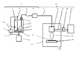
図1は本発明による成膜装置を説明する図である。本装置は粉体供給部1と成膜部20とから構成される。粉体を貯留する密閉容器2にはモーター7により回転可能な、第1の電極として円板状の導電性の円板3が設置されている。導電性円板3の上方に導電性円板3と対向する、第2の電極4が設置されている。これら一対の電極としての円板3と電極4に、電源5により電圧をかけて、放電6を発生することができるようになっている。この時使用される電源5は導電性円板3と電極4の間に放電を起こすことができればよく、交流電源でも直流電源でも使用可能である。一対の電極のうち、一方の電極である導電性円板3の上には成膜材料の粉体8が載置され、導電性円板3と共に回転する。
FIG. 1 is a diagram illustrating a film forming apparatus according to the present invention. This apparatus includes a powder supply unit 1 and a
放電6が起こると、粉体8が凝集している場合でも、放電6の近辺の粉体8が凝集を解かれると同時に空中に舞上り微粒子状(煙状)の粉体9になる。このとき、放電が起こった位置の円板3上の粉体は放電位置以外の場所に移動してしまうので、円板3を回転させて粉体8を放電部に移動する必要がある。密閉容器2へは、図示しないガス供給設備に接続されている気体供給管10により、気体が供給されている。前記ガス供給設備はガスの流量を正確に制御できる装置を備えている。
When the
気体は不活性ガスでプラズマを励起できる気体であればよい。たとえば、アルゴン、ヘリウム、窒素等を使用することができ、特にアルゴンが好ましい。 The gas may be any gas that can excite plasma with an inert gas. For example, argon, helium, nitrogen or the like can be used, and argon is particularly preferable.
気体供給管10を通して一定量の気体が密閉容器2に入ると、密閉容器2内の圧力が上昇し、排出管11から気体は流れ出ていく。この気体の流れに戴って、舞い上がった粉体9も排出管11に流れる。排出管11に流れこんだ粉体は、フレキシブルチュ−ブ13を通った後、粉体流量計14を通過する時に流量が測定される。
When a certain amount of gas enters the sealed
粉体流量計14の測定結果をもとに粉体の供給量を制御する。制御方法としては、放電電圧、円板3の回転速度、気体の流量、排出管11の出口の高さ等があり、適宜選択することができる。
The supply amount of the powder is controlled based on the measurement result of the
排出管11はベローズ12により密閉容器2に接続されているため、密閉を保ったまま上下に移動可能となっている。これらを適宜調整することで、所望の粉体供給量が得られる。
Since the discharge pipe 11 is connected to the sealed
成膜部20に送られた粉体が混合された気体は、成膜室27内のプラズマ発生装置であるプラズマガン21に供給される。プラズマガン21には、マイクロ波発生装置であるマイクロ波発振機22から導波管23を通してマイクロ波が供給され、排出管11から送られてきた気体をプラズマ化し、プラズマ炎24を発生する。
The gas mixed with the powder sent to the
排出管11を気体と共に搬送されてきた粉体8はプラズマ炎24内で気化し、基板25上に薄膜となり堆積する。基板ホルダー26はXYステージ上にあり、基板上の全面に成膜出来るように、広範囲に移動可能となっている。
The
以上のような構成により、プラズマガンに必要量のプラズマを励起する気体と、成膜材料としての粉体の必要量を安定して供給することが可能となる。また、粉体は凝集を解いた状態で供給することができるので、これによって品質の良い薄膜を形成することが出来る。 With the above-described configuration, it is possible to stably supply a necessary amount of a gas that excites a necessary amount of plasma and a powder as a film forming material to the plasma gun. In addition, since the powder can be supplied in a state where the aggregation is released, a thin film with good quality can be formed thereby.
図1を参照しつつ、本発明の成膜装置及び成膜方法を説明する。 The film forming apparatus and film forming method of the present invention will be described with reference to FIG.
粉体を貯留する密閉容器2は透明なアクリル製で内部を観察することができる様になっている。この密閉容器にはモーター7により回転することができるステンレス製の円板3が設置されている。モーター7からの回転を円板3に伝える軸には回転導入器を用いているため、密閉容器2の密閉性は保たれる。
The sealed
円板3の上には成膜材料として平均粒径5μmのhBN粉体8が載置され円板3と共に回転する。さらに円板3の上方には円板3と対向する電極4が設置されている。電極4はステンレス製で先端は半径1mmの球形状とした。
On the disk 3,
円板3と電極4の間には電源5により約10kV、20kHzの電圧をかけ、円板3と電極4の間に放電を起こした。この放電は一般にコロナ放電と呼ばれている現象であり、電極間に線状の火花が見られる放電のときにhBN粉体8がよく舞い上がった。この時、hBN粉体8は凝集していたが、放電6の近辺のhBN粉体8が凝集を解かれると同時に気中に舞い上り煙状の粉体9になった。
A voltage of about 10 kV and 20 kHz was applied between the disk 3 and the
円板3上のhBN粉体8は放電した部分から別の場所に移動してしまうため、円板3をおよそ毎分30回転の速さで回転し、hBN粉体8を放電位置へ供給した。ここでは、円板3の回転速度を変化させることによって粉体の供給量を制御した。
Since the
密閉容器2へは図示しないアルゴンガスの供給設備に接続されている気体供給管10により、アルゴンガスをマスフローコントローラーで制御し、100sccmの流量で供給した。この様にアルゴンガスを密閉容器2に供給すると、密閉容器2内の圧力が上昇し排出管11からアルゴンが流れ出ていく。ただし、初期においては容器内の空気がなくなるまで充分な時間、アルゴンガスを供給し続けた。
Argon gas was controlled by a mass flow controller and supplied at a flow rate of 100 sccm to the sealed
その後、放電を開始してhBN粉体8を舞い上げた。舞い上がった粉体9はアルゴンガスの流れに戴って、排出管11に流れた。排出管11に流れこんだ粉体はフレキシブルチュ−ブ13を通り粉体流量計14に至った。この粉体流量計14には光学式のものを使用した。
Then, discharge was started and the
粉体流量計14の測定結果をもとに粉体の供給量を0.01g/minに制御した。粉体の舞い上がり量を制御するために円板3の回転速度を制御する方法を用いた。成膜部20に流れたアルゴンガスと粉体を成膜室27内のプラズマガン21に供給した。
Based on the measurement result of the
プラズマガン21には2.45GHzのマイクロ波を発振機22から導波管23を通して供給した。マイクロ波の出力は300Wとし、整合器28により整合を取った。プラズマガン21では配管15から供給されたアルゴンガスをプラズマ化し、プラズマ炎24を発生させた。
The
配管15からアルゴンガスと共に供給された粉体はプラズマ炎24内で気化し、シリコン基板25上に薄膜となり堆積した。この時、基板ホルダー26は図示しないXYステージ上にあり、成膜時にはシリコン基板25の全面に膜が形成するように、走査移動を行った。この様にして、基板全面に0.5μmの厚さで窒化ホウ素の膜を形成した。
The powder supplied from the pipe 15 together with the argon gas was vaporized in the
本実施例では粉体の舞い上がり量の制御を、円板3の回転速度の変化により行ったが、更に、円板3と隙間を隔てたすり切り板を設け、円板3上の粉体の量を一定に保つと、制御精度が向上する。又、粉体の舞い上がり量を制御する方法として、放電電圧を変化させる方法もある。更に、粉体の供給量を制御する方法として、排出管11の高さを変える方法がある。排出管11はベローズ12によって密閉容器2と接続されているため、上下方向の移動が可能である。
In this embodiment, the amount of powder rising is controlled by a change in the rotational speed of the disk 3, but a grinding plate that is spaced from the disk 3 is provided, and the amount of powder on the disk 3 is If the value is kept constant, the control accuracy is improved. There is also a method of changing the discharge voltage as a method of controlling the amount of powder rising. Further, there is a method of changing the height of the discharge pipe 11 as a method of controlling the supply amount of the powder. Since the discharge pipe 11 is connected to the sealed
又、本実施例ではプラズマを発生するエネルギーとして、マイクロ波を用いたが、プラズマを発生出来れば、マイクロ波に限った事でなく13.56MHzのRF高周波等も使用できる。 In this embodiment, microwaves are used as energy for generating plasma. However, if plasma can be generated, not only microwaves but also 13.56 MHz RF high frequency can be used.
以上説明したように本発明によれば、凝集した粉体で有っても容易に解砕しながら気中に分散することが出来るので、その後の微量な粉体の供給が可能となる。更に、気中に舞い上がった解砕後の粉体を測定しながら供給量を制御することが出来るので、安定供給が可能である。また、キャリアガスと粉体の供給量を個別に制御出来るので、プラズマを良好な状態に保つことができる。よって、本発明の成膜装置では膜中に凝集粒の無い良好な成膜が可能となる。 As described above, according to the present invention, even agglomerated powder can be easily crushed and dispersed in the air, so that a small amount of powder can be supplied thereafter. Furthermore, since the supply amount can be controlled while measuring the powder after pulverization that has risen in the air, stable supply is possible. Further, since the supply amounts of the carrier gas and the powder can be individually controlled, the plasma can be maintained in a good state. Therefore, the film forming apparatus of the present invention enables good film formation without aggregated particles in the film.
1・・・粉体供給部
2・・・密閉容器
3・・・円板
4・・・電極
5・・・電源
6・・・放電
8・・・粉体
9・・・舞い上がった粉体
10・・・気体供給管
11・・・排出管
20・・・成膜部
21・・・プラズマガン
25・・・基板
DESCRIPTION OF SYMBOLS 1 ...
Claims (6)
密閉容器(2)と、
前記密閉容器(2)内に設置された一対の電極(3、4)であって、粉体をその間に載置する、一対の電極(3、4)と、
前記密閉容器(2)内に気体を供給するための供給管(10)と、
前記粉体を前記密閉容器(2)内に舞上がらせるために、前記一対の電極(3、4)間に放電を生じさせるための電源(5)と、
前記舞上がらせた粉体と前記供給された気体とを前記密閉容器(2)内から排出するための排出管(11)と、
を有する粉体供給部(1)、及び
基板(25)を載置するための基板ホルダー(26)と前記排出管(11)から前記粉体と前記気体とが供給されるプラズマ発生装置(21)とを有する成膜室(27)と、
前記プラズマ発生装置(21)に高周波を供給する高周波供給装置(22)と、
を有する成膜部(20)、
を含むことを特徴とする、成膜装置。 A film forming apparatus using powder as a film forming material,
A sealed container (2);
A said closed container (2) a pair of electrodes installed in the (3,4), placing the powder therebetween, a pair of electrodes (3, 4),
Supply pipe for supplying gas to the closed container (2) in (10),
A power source (5) for generating a discharge between the pair of electrodes (3, 4) to cause the powder to fly into the sealed container (2) ;
A discharge pipe (11) for discharging the soaked powder and the supplied gas from the sealed container (2) ;
And a plasma generator (21 ) to which the powder and the gas are supplied from the substrate holder (26) for placing the substrate (25) and the discharge pipe (11). ) Having a film forming chamber (27),
A high frequency supply device (22) for supplying a high frequency to the plasma generator (21);
A film forming section (20) having
A film forming apparatus comprising:
密閉容器(2)内に気体を供給しながら、前記密閉容器(2)内に設置された一対の電極(3、4)間に放電を生じさせて、前記一対の電極(3、4)間に載置された粉体を前記密閉容器(2)内に舞上げるとともに前記粉体の凝集を解き、
前記舞上げられた前記粉体と前記供給された気体とを、排出管(11)を通じてプラズマ発生装置(21)に搬送し、
前記プラズマ発生装置(21)によりプラズマを発生させて、前記排出管(11)から搬送された前記気体をプラズマ化し、前記排出管(11)から搬送された前記粉体を気化させて基板(25)上に膜を形成することを特徴とする、膜の製造方法。 A method for manufacturing a membrane , comprising:
While supplying a gas to the sealed container (2) in the closed container (2) by causing discharge between the installed pair of electrodes (3, 4) in the pair of electrodes (3, 4) between The powder placed on the airtight container (2) is lifted and the powder is agglomerated,
Transporting the so- powdered powder and the supplied gas to a plasma generator (21) through a discharge pipe (11);
Plasma is generated by the plasma generator (21), the gas transported from the discharge pipe (11) is turned into plasma , and the powder transported from the discharge pipe (11) is vaporized to form a substrate (25 ) A method for producing a film, comprising forming a film thereon.
Priority Applications (1)
| Application Number | Priority Date | Filing Date | Title |
|---|---|---|---|
| JP2012099773A JP5911368B2 (en) | 2012-04-25 | 2012-04-25 | Film forming apparatus and film forming method |
Applications Claiming Priority (1)
| Application Number | Priority Date | Filing Date | Title |
|---|---|---|---|
| JP2012099773A JP5911368B2 (en) | 2012-04-25 | 2012-04-25 | Film forming apparatus and film forming method |
Publications (3)
| Publication Number | Publication Date |
|---|---|
| JP2013227612A JP2013227612A (en) | 2013-11-07 |
| JP2013227612A5 JP2013227612A5 (en) | 2015-06-11 |
| JP5911368B2 true JP5911368B2 (en) | 2016-04-27 |
Family
ID=49675529
Family Applications (1)
| Application Number | Title | Priority Date | Filing Date |
|---|---|---|---|
| JP2012099773A Expired - Fee Related JP5911368B2 (en) | 2012-04-25 | 2012-04-25 | Film forming apparatus and film forming method |
Country Status (1)
| Country | Link |
|---|---|
| JP (1) | JP5911368B2 (en) |
Families Citing this family (1)
| Publication number | Priority date | Publication date | Assignee | Title |
|---|---|---|---|---|
| CN114032510A (en) * | 2021-11-17 | 2022-02-11 | 中国科学院半导体研究所 | Growth method of vertical arrays of tellurium nanowires |
Family Cites Families (11)
| Publication number | Priority date | Publication date | Assignee | Title |
|---|---|---|---|---|
| JPS6320032A (en) * | 1986-07-14 | 1988-01-27 | Res Dev Corp Of Japan | Production of hyperfine particle having film |
| JPS6430636A (en) * | 1987-07-27 | 1989-02-01 | Ulvac Corp | Method and apparatus for producing compound superfine powder |
| JP2615190B2 (en) * | 1989-03-14 | 1997-05-28 | 三菱重工業株式会社 | Method for producing cubic boron nitride |
| JP2853046B2 (en) * | 1989-06-21 | 1999-02-03 | 日新製鋼株式会社 | Ultra fine powder production equipment |
| JPH042781A (en) * | 1990-04-20 | 1992-01-07 | Vacuum Metallurgical Co Ltd | Aerosol producing equipment |
| JPH04281840A (en) * | 1991-03-07 | 1992-10-07 | Takeshi Masumoto | Production of ultrafine particle of metallic oxide and producing equipment |
| JP3033861B2 (en) * | 1991-08-30 | 2000-04-17 | 豊信 吉田 | Powder supply device |
| JPH06136519A (en) * | 1992-10-23 | 1994-05-17 | Matsushita Electric Ind Co Ltd | Crystalline film forming method and film forming apparatus |
| JPH07223899A (en) * | 1993-08-30 | 1995-08-22 | Tonen Corp | Method for manufacturing silicon laminate |
| JPH08158033A (en) * | 1994-12-02 | 1996-06-18 | Nisshin Steel Co Ltd | Production of fine-structure thick film material and device therefor |
| JP4526162B2 (en) * | 2000-06-06 | 2010-08-18 | 独立行政法人産業技術総合研究所 | Ceramic structure manufacturing equipment |
-
2012
- 2012-04-25 JP JP2012099773A patent/JP5911368B2/en not_active Expired - Fee Related
Also Published As
| Publication number | Publication date |
|---|---|
| JP2013227612A (en) | 2013-11-07 |
Similar Documents
| Publication | Publication Date | Title |
|---|---|---|
| US10125421B2 (en) | Plasma CVD apparatus, plasma CVD method, and agitating device | |
| TWI704059B (en) | Additive manufacturing with laser and gas flow | |
| JP2005523142A (en) | Protective coating composition | |
| US9034438B2 (en) | Deposition method using an aerosol gas deposition for depositing particles on a substrate | |
| JP6092863B2 (en) | Coating methods using special powdered coating materials and the use of such coating materials | |
| CN106660270A (en) | Additive Manufacturing Using Lasers and Plasma | |
| JP5669328B2 (en) | Deposition method | |
| EP3327172A9 (en) | Powder coating apparatus | |
| JP6485628B2 (en) | Film forming method and film forming apparatus | |
| US20040115872A1 (en) | Method and device for generating an activated gas curtain for surface treatment | |
| JP5911368B2 (en) | Film forming apparatus and film forming method | |
| JP3809860B2 (en) | Composite structure manufacturing method and composite structure manufacturing apparatus | |
| JP5909737B2 (en) | Yttria film deposition method | |
| RU2486990C1 (en) | Device to apply coats on powders | |
| Chen et al. | Application of a novel atmospheric pressure plasma fluidized bed in the powder surface modification | |
| WO2022009340A1 (en) | Cover member for plasma processing device, plasma processing, and membrane production method | |
| JP4526162B2 (en) | Ceramic structure manufacturing equipment | |
| JP4776959B2 (en) | Water repellent treatment method | |
| JP5541763B2 (en) | Method for attaching nanoparticles to substrate particles | |
| JP2009046741A (en) | Method for forming fine-particle film | |
| JP7187073B1 (en) | Ceramic coating system and method | |
| JP2015086238A (en) | Abrasive, abrasive article, abrasive aerosol, abrasive member and method for producing abrasive | |
| JP2021167459A (en) | Film deposition apparatus | |
| CN103184403A (en) | Plasma film-forming device | |
| JP2013185172A (en) | Apparatus for producing fine metal powder |
Legal Events
| Date | Code | Title | Description |
|---|---|---|---|
| A521 | Request for written amendment filed |
Free format text: JAPANESE INTERMEDIATE CODE: A523 Effective date: 20150417 |
|
| A621 | Written request for application examination |
Free format text: JAPANESE INTERMEDIATE CODE: A621 Effective date: 20150417 |
|
| A977 | Report on retrieval |
Free format text: JAPANESE INTERMEDIATE CODE: A971007 Effective date: 20151112 |
|
| A131 | Notification of reasons for refusal |
Free format text: JAPANESE INTERMEDIATE CODE: A131 Effective date: 20151117 |
|
| A521 | Request for written amendment filed |
Free format text: JAPANESE INTERMEDIATE CODE: A523 Effective date: 20160115 |
|
| TRDD | Decision of grant or rejection written | ||
| A01 | Written decision to grant a patent or to grant a registration (utility model) |
Free format text: JAPANESE INTERMEDIATE CODE: A01 Effective date: 20160301 |
|
| A61 | First payment of annual fees (during grant procedure) |
Free format text: JAPANESE INTERMEDIATE CODE: A61 Effective date: 20160329 |
|
| R151 | Written notification of patent or utility model registration |
Ref document number: 5911368 Country of ref document: JP Free format text: JAPANESE INTERMEDIATE CODE: R151 |
|
| LAPS | Cancellation because of no payment of annual fees |