JP5906339B2 - Game machine - Google Patents
Game machine Download PDFInfo
- Publication number
- JP5906339B2 JP5906339B2 JP2015083024A JP2015083024A JP5906339B2 JP 5906339 B2 JP5906339 B2 JP 5906339B2 JP 2015083024 A JP2015083024 A JP 2015083024A JP 2015083024 A JP2015083024 A JP 2015083024A JP 5906339 B2 JP5906339 B2 JP 5906339B2
- Authority
- JP
- Japan
- Prior art keywords
- game board
- game
- ball
- board surface
- synthetic resin
- Prior art date
- Legal status (The legal status is an assumption and is not a legal conclusion. Google has not performed a legal analysis and makes no representation as to the accuracy of the status listed.)
- Active
Links
- 239000000057 synthetic resin Substances 0.000 claims description 77
- 229920003002 synthetic resin Polymers 0.000 claims description 77
- 238000005034 decoration Methods 0.000 claims description 63
- 230000000694 effects Effects 0.000 description 85
- 125000006850 spacer group Chemical group 0.000 description 36
- 230000002093 peripheral effect Effects 0.000 description 33
- 230000015654 memory Effects 0.000 description 26
- 230000002265 prevention Effects 0.000 description 24
- 239000000843 powder Substances 0.000 description 19
- 238000003780 insertion Methods 0.000 description 17
- 230000037431 insertion Effects 0.000 description 17
- 238000004519 manufacturing process Methods 0.000 description 14
- 238000003860 storage Methods 0.000 description 14
- 210000000078 claw Anatomy 0.000 description 12
- 230000006870 function Effects 0.000 description 9
- 238000007790 scraping Methods 0.000 description 9
- 239000000758 substrate Substances 0.000 description 8
- 230000007246 mechanism Effects 0.000 description 7
- 238000012545 processing Methods 0.000 description 7
- 239000011521 glass Substances 0.000 description 6
- 239000000463 material Substances 0.000 description 6
- 238000000034 method Methods 0.000 description 6
- 239000004925 Acrylic resin Substances 0.000 description 5
- 229920000178 Acrylic resin Polymers 0.000 description 5
- 238000001514 detection method Methods 0.000 description 5
- 238000012986 modification Methods 0.000 description 5
- 230000004048 modification Effects 0.000 description 5
- 230000008569 process Effects 0.000 description 5
- 238000013461 design Methods 0.000 description 4
- 230000001360 synchronised effect Effects 0.000 description 4
- 230000007704 transition Effects 0.000 description 4
- 230000008859 change Effects 0.000 description 3
- 230000001276 controlling effect Effects 0.000 description 3
- 238000010586 diagram Methods 0.000 description 3
- 238000005553 drilling Methods 0.000 description 3
- 238000010304 firing Methods 0.000 description 3
- 238000009434 installation Methods 0.000 description 3
- 239000011120 plywood Substances 0.000 description 3
- 229920005989 resin Polymers 0.000 description 3
- 239000011347 resin Substances 0.000 description 3
- 230000004044 response Effects 0.000 description 3
- 230000015572 biosynthetic process Effects 0.000 description 2
- 238000007599 discharging Methods 0.000 description 2
- 230000005484 gravity Effects 0.000 description 2
- 238000012423 maintenance Methods 0.000 description 2
- 239000002184 metal Substances 0.000 description 2
- 230000000149 penetrating effect Effects 0.000 description 2
- 238000003825 pressing Methods 0.000 description 2
- 238000003786 synthesis reaction Methods 0.000 description 2
- 230000004308 accommodation Effects 0.000 description 1
- 238000007792 addition Methods 0.000 description 1
- 230000004397 blinking Effects 0.000 description 1
- 239000003990 capacitor Substances 0.000 description 1
- 238000005520 cutting process Methods 0.000 description 1
- 230000007423 decrease Effects 0.000 description 1
- 238000000605 extraction Methods 0.000 description 1
- 230000001771 impaired effect Effects 0.000 description 1
- 239000004973 liquid crystal related substance Substances 0.000 description 1
- 239000000113 methacrylic resin Substances 0.000 description 1
- 238000012544 monitoring process Methods 0.000 description 1
- 238000000465 moulding Methods 0.000 description 1
- 229920005668 polycarbonate resin Polymers 0.000 description 1
- 239000004431 polycarbonate resin Substances 0.000 description 1
- 230000001105 regulatory effect Effects 0.000 description 1
- 238000005096 rolling process Methods 0.000 description 1
- 230000005236 sound signal Effects 0.000 description 1
- 230000002194 synthesizing effect Effects 0.000 description 1
- 238000012546 transfer Methods 0.000 description 1
- 238000011144 upstream manufacturing Methods 0.000 description 1
Images


Description
本発明は、透光性を有する合成樹脂板からなり、遊技盤面側に遊技領域が形成された遊技盤を備える遊技機に関する。 The present invention relates to a gaming machine including a gaming board made of a synthetic resin plate having translucency and having a gaming area formed on the gaming board surface side.
従来、遊技盤面側に障害釘が打設される遊技盤はベニヤ合板等にて構成されるとともに、該遊技盤面側には化粧板が取り付けられ、該化粧板の表面に模様や絵柄が施されたセル版等を貼付することにより遊技盤面に装飾が施されるが、装飾が平面的であるため、視覚的に迫力のある装飾を提供するには限界があった。 Conventionally, a game board in which obstacle nails are placed on the game board surface side is composed of veneer plywood or the like, and a decorative board is attached to the game board surface side, and a pattern or a pattern is applied to the surface of the decorative board. Although the game board surface is decorated by attaching a cell version or the like, there is a limit to providing visually powerful decoration because the decoration is flat.
また、遊技盤面に立体状の装飾部材を配設することで遊技盤面を装飾するものがあるが、例えば識別情報を可変表示可能な可変表示部が設けられ、該可変表示部において識別情報の可変表示の表示結果が特定表示結果となった場合に「大当り」が発生し、所定の遊技価値を遊技者に与えるように構成されているパチンコ遊技機においては、可変表示部に対応する演出用の可変表示装置や役物装置等が大型化される傾向にあるため、遊技盤面に多数の装飾部材を配設すると遊技球の通過領域を十分に確保できなくなり、遊技の面白みが損なわれることがあった。 In addition, there are some which decorate the game board surface by arranging a three-dimensional decoration member on the game board surface. For example, a variable display section capable of variably displaying the identification information is provided, and the variable display section can change the identification information. In a pachinko gaming machine configured to give a predetermined game value to a player when a display result of the display is a specific display result, a pachinko gaming machine configured to give the player a predetermined game value Since variable display devices, accessory devices, etc. tend to be large, if a large number of decorative members are arranged on the game board surface, a sufficient passing area for the game ball cannot be secured, and the fun of the game may be impaired. It was.
そこで、遊技盤を透明なアクリル樹脂板にて構成するとともに、その裏面側に立体状の装飾部材や表示装置を配設し、該アクリル樹脂板を通して装飾部材や表示装置を視認可能とすることで、遊技球の通過領域を確保しながら遊技盤面を装飾可能としたものが提案されている(例えば、特許文献1参照)。 Therefore, by configuring the game board with a transparent acrylic resin plate and arranging a three-dimensional decorative member or display device on the back side thereof, the decorative member or display device can be visually recognized through the acrylic resin plate. There has been proposed a game board surface that can be decorated while securing a passing area of the game ball (see, for example, Patent Document 1).
しかしながら、上記特許文献1に記載の遊技機のように遊技盤をアクリル樹脂等の合成樹脂板にて構成する場合、該合成樹脂板の遊技盤面と該遊技盤面上に配置される種々の部材とが擦れることにより削られた樹脂の粉が遊技盤面に付着して汚れてしまい、該遊技盤面の装飾性が低減するという問題があった。 However, when the game board is configured with a synthetic resin plate such as an acrylic resin as in the gaming machine described in Patent Document 1, the game board surface of the synthetic resin plate and various members disposed on the game board surface; There is a problem that the resin powder scraped by rubbing is attached to the surface of the game board and becomes dirty, and the decorativeness of the surface of the game board is reduced.
本発明は、このような問題点に着目してなされたもので、遊技盤を透光性を有する合成樹脂板により構成する場合において、該遊技盤面の装飾性が低減することを防止できる遊技機を提供することを目的とする。 The present invention has been made paying attention to such problems, and in the case where the game board is made of a synthetic resin plate having translucency, a gaming machine capable of preventing the decorativeness of the game board surface from being reduced. The purpose is to provide.
前記課題を解決するために、本発明の請求項1に記載の遊技機は、
透光性を有する合成樹脂板(200)からなり、遊技媒体(遊技球)が流下可能な遊技領域(7)が形成された遊技盤(6)を備える遊技機(パチンコ遊技機1)であって、
遊技盤面(200a)上における前記遊技領域に配設され、該遊技領域を装飾する装飾部材(25L,25R、650、センター飾り11等)と、
前記装飾部材の前記遊技盤面に沿う方向への移動を規制するための規制部と、
を備え、
前記装飾部材を前記遊技盤面に取り付けた取付状態において、該装飾部材における前記遊技盤面側の縁辺部(H)と前記遊技盤面との間に、該縁辺部と前記遊技盤面との当接を防止するための隙間が形成され{縁辺部Hに切欠凹溝KMを形成して隙間を形成する。(図21,図25,図27参照)}、
前記装飾部材(25L,25R、センター飾り11等)は、前記縁辺部(H)よりも内側から前記遊技盤面側に突設され、前記取付状態において前記遊技盤面に当接する当接部(凸部654)を備える(図27参照)
ことを特徴としている。
この特徴によれば、装飾部材に遊技球との接触により振動が生じても、該装飾部材における遊技盤面側の縁辺部は遊技盤面に直接接触して擦れることがないので、削られた粉が遊技盤面における装飾部材の近傍に付着して遊技盤面の装飾性が低減することが防止される。
In order to solve the above-mentioned problem, a gaming machine according to claim 1 of the present invention provides:
A gaming machine (pachinko gaming machine 1) comprising a gaming board (6) made of a synthetic resin plate (200) having translucency and formed with a gaming area (7) in which gaming media (game balls) can flow down. And
A decorative member (25L, 25R, 650,
A restricting portion for restricting movement of the decorative member in a direction along the game board surface;
With
When the decoration member is attached to the game board surface, contact between the edge portion (H) on the game board surface side of the decoration member and the game board surface is prevented between the edge portion and the game board surface. A gap is formed to form a {notch groove KM in the edge portion H to form a gap. (See FIGS. 21, 25, and 27)},
The decorative member (25L, 25R,
It is characterized by that.
According to this feature, even if the decorative member vibrates due to contact with the game ball, the edge on the game board surface side of the decorative member does not directly rub against the game board surface. It is prevented that the decorativeness of the game board surface is reduced by adhering to the vicinity of the decoration member on the game board surface.
本発明の手段1の遊技機は、請求項1に記載の遊技機であって、
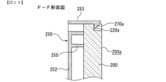
前記遊技盤は、前記合成樹脂板を取り付ける取付面が設けられたスペーサ部材(250)を含み、
前記スペーサ部材(250)は、前記取付面の周縁箇所に係止部(弾性係止爪270a〜270d)が突設され、
前記合成樹脂板(200)は、前記係止部に対応する側面に前記係止部が係止される被係止部(係止段部220a〜220d)が形成され、
前記係止部の突出長さ寸法を、前記合成樹脂板の厚み幅寸法よりも短寸とした(図19参照)
ことを特徴としている。
この特徴によれば、係止部の突出長さ寸法を、合成樹脂板の厚み幅寸法よりも短寸としたため、合成樹脂板の遊技盤面よりも前面側に突出して、製造時や保管、搬送時等において係止部が床面や他の遊技盤等と接触して破損することが防止される。
The gaming machine of means 1 of the present invention is the gaming machine according to claim 1,
The game board includes a spacer member (250) provided with an attachment surface for attaching the synthetic resin plate,
The spacer member (250) is provided with locking portions (
The synthetic resin plate (200) is formed with locked portions (locking
The protruding length dimension of the locking portion is shorter than the thickness width dimension of the synthetic resin plate (see FIG. 19).
It is characterized by that.
According to this feature, the protruding length dimension of the locking portion is shorter than the thickness width dimension of the synthetic resin plate, so that it protrudes to the front side of the game board surface of the synthetic resin plate, and is manufactured, stored and transported. In some cases, the locking portion is prevented from being damaged due to contact with the floor or other game boards.
本発明の手段2の遊技機は、請求項1または手段1に記載の遊技機であって、
前記装飾部材(25L,25R、センター飾り11等)は、
前記遊技盤面(200a)側の前記縁辺部(H)よりも内側に配置され、前記遊技盤面に取り付けるための取付部材(取付ネジ652)が挿通される取付部と、
前記取付部の周囲から前記遊技盤面側に突設され、前記取付状態において前記遊技盤面に当接する当接部(凸部654)と、
を備える(図27参照)
ことを特徴としている。
この特徴によれば、当接部が縁辺部よりも内側に配置されていることで、当接部と遊技盤面とが擦れても、削られた粉は隠蔽されるので目立つことがないばかりか、当接部は取付部材により遊技盤面に対して強固に取り付けられて該遊技盤面と擦れにくいため、削れた粉が生じにくくなる。
The gaming machine of means 2 of the present invention is the gaming machine according to claim 1 or means 1,
The decorative members (25L, 25R,
An attachment portion that is disposed inside the edge portion (H) on the game board surface (200a) side and through which an attachment member (attachment screw 652) for attachment to the game board surface is inserted;
A contact portion (convex portion 654) that protrudes from the periphery of the attachment portion to the game board surface side and contacts the game board surface in the attachment state;
(See FIG. 27)
It is characterized by that.
According to this feature, the abutting portion is arranged on the inner side of the edge portion, so that even if the abutting portion and the game board surface are rubbed, the scraped powder is concealed so that it does not stand out. The abutment portion is firmly attached to the game board surface by the attachment member and is not easily rubbed against the game board surface, so that scraped powder is hardly generated.
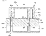
本発明の手段3の遊技機は、請求項1、手段1、手段2のいずれかに記載の遊技機であって、
前記装飾部材(650)から前記遊技盤面(200a)側に向けて突設された装飾部材用位置決め突部(位置決めピン653)と、
前記遊技盤(合成樹脂板200)における前記遊技盤面の裏面側に取り付けられ、遊技に関連する遊技用部品が組み付けられるユニット部材(スペーサ部材250)と、
前記ユニット部材から前記遊技盤側に向けて突設されるユニット部材用位置決め突部(位置決めピン657)と、
前記遊技盤に貫通して形成される貫通穴(位置決め穴656)と、
を備え、
前記貫通穴に、前記装飾部材用位置決め突部を前記遊技盤面側から嵌合するとともに、前記ユニット部材用位置決め突部を前記遊技盤面の裏面側から嵌合した(図27参照)
ことを特徴としている。
この特徴によれば、貫通穴を装飾部材用位置決め突部とユニット部材用位置決め突部とで共用することができるため、それぞれの位置決め用穴を別個に形成する場合に比べて遊技盤の強度低下を防止できるばかりか、穴あけ加工の手間を省くことができる。
The gaming machine of means 3 of the present invention is the gaming machine according to any one of claim 1, means 1, and means 2,
A decorative member positioning protrusion (positioning pin 653) projecting from the decorative member (650) toward the game board surface (200a),
A unit member (spacer member 250) attached to the back side of the gaming board surface of the gaming board (synthetic resin plate 200) and assembled with gaming parts related to gaming;
A positioning projection for unit member (positioning pin 657) projecting from the unit member toward the game board,
A through hole (positioning hole 656) formed through the game board;
With
The decorative member positioning projection is fitted into the through hole from the game board surface side, and the unit member positioning projection is fitted from the back side of the game board surface (see FIG. 27).
It is characterized by that.
According to this feature, the through hole can be shared by the positioning projection for the decorative member and the positioning projection for the unit member, so that the strength of the game board is reduced compared to the case where each positioning hole is formed separately. As well as the need for drilling.
本発明の実施例を図面に基づいて以下に説明する。 Embodiments of the present invention will be described below with reference to the drawings.
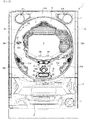
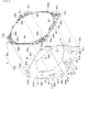
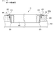
まず、遊技機の一例であるパチンコ遊技機1の全体の構成について説明する。図1はパチンコ遊技機1を正面からみた正面図である。 First, the overall configuration of a pachinko gaming machine 1 that is an example of a gaming machine will be described. FIG. 1 is a front view of the pachinko gaming machine 1 as seen from the front.
パチンコ遊技機1は、図1、図2及び図4に示すように、縦長の方形枠状に形成された外枠100と、外枠100の内側に開閉可能に取り付けられ、後述する遊技盤6が取り付けられる遊技枠110と、遊技枠110に開閉可能に設けられている額縁状に形成されたガラス扉枠2と、機構部品等が取り付けられる機構板120と、から主に構成される。
As shown in FIGS. 1, 2 and 4, the pachinko gaming machine 1 is provided with an
ガラス扉枠2の下部表面には打球供給皿(上皿)3がある。打球供給皿3の下部には、打球供給皿3に収容しきれない遊技球を貯留する余剰球受皿4や、打球を発射する打球操作ハンドル(操作ノブ)5が設けられている。また、ガラス扉枠2の背面には、遊技盤6が遊技枠110に対して着脱可能に取り付けられている。なお、遊技盤6は、それを構成する板状の合成樹脂板と、その合成樹脂板に取り付けられた種々の部品とを含む構造体であり、これらの詳細な構造に関しては後述することとする。また、遊技盤6の前面には、打ち込まれた遊技球が流下可能な遊技領域7が形成されている。
On the lower surface of the glass door frame 2 is a hitting ball supply tray (upper plate) 3. Under the hitting ball supply tray 3, there are provided a surplus ball receiving tray 4 for storing game balls that cannot be accommodated in the hitting ball supply tray 3, and a hitting operation handle (operation knob) 5 for firing the hitting ball. The
遊技領域7の中央付近には、液晶表示装置(LCD)で構成された演出表示装置9が設けられている。演出表示装置9では、第1特別図柄または第2特別図柄の可変表示に同期した演出図柄(飾り図柄)の可変表示(変動)が行われる。よって、演出表示装置9は、識別情報としての演出図柄(飾り図柄)の可変表示を行う可変表示装置に相当する。演出表示装置9は、演出制御基板に搭載されている演出制御用マイクロコンピュータによって制御される。演出制御用マイクロコンピュータが、第1特別図柄表示器8a(図3参照)で第1特別図柄の可変表示が実行されているときに、その可変表示に伴って演出表示装置9で演出表示を実行させ、第2特別図柄表示器8b(図3参照)で第2特別図柄の可変表示が実行されているときに、その可変表示に伴って演出表示装置で演出表示を実行させるので、遊技の進行状況を把握しやすくすることができる。
An
遊技盤6における右側下部位置には、識別情報としての第1特別図柄を可変表示する第1特別図柄表示器(第1可変表示手段)8a(図12、図13参照)が設けられている。この実施例では、第1特別図柄表示器8aは、0〜9の数字を可変表示可能な簡易で小型の表示器(例えば7セグメントLED)で実現されている。すなわち、第1特別図柄表示器8aは、0〜9の数字(または、記号)を可変表示するように構成されている。また、第1特別図柄表示器8aの上方位置には、識別情報としての第2特別図柄を可変表示する第2特別図柄表示器(第2可変表示手段)8b(図12、図13参照)が設けられている。第2特別図柄表示器8bは、0〜9の数字を可変表示可能な簡易で小型の表示器(例えば7セグメントLED)で実現されている。すなわち、第2特別図柄表示器8bは、0〜9の数字(または、記号)を可変表示するように構成されている。
A first special symbol display (first variable display means) 8a (see FIGS. 12 and 13) for variably displaying a first special symbol as identification information is provided at a lower right position on the
この実施例では、第1特別図柄の種類と第2特別図柄の種類とは同じ(例えば、ともに0〜9の数字)であるが、種類が異なっていてもよい。また、第1特別図柄表示器8aおよび第2特別図柄表示器8bは、それぞれ、例えば2つの7セグメントLED等を用いて00〜99の数字(または、2桁の記号)を可変表示するように構成されていてもよい。
In this embodiment, the type of the first special symbol and the type of the second special symbol are the same (for example, both 0 to 9), but the types may be different. The first
以下、第1特別図柄と第2特別図柄とを特別図柄と総称することがあり、第1特別図柄表示器8aと第2特別図柄表示器8bとを特別図柄表示器と総称することがある。
Hereinafter, the first special symbol and the second special symbol may be collectively referred to as a special symbol, and the first
第1特別図柄または第2特別図柄の可変表示は、可変表示の実行条件である第1始動条件または第2始動条件が成立(例えば、遊技球が第1始動入賞口13または第2始動入賞口14に入賞したこと)した後、可変表示の開始条件(例えば、保留記憶数が0でない場合であって、第1特別図柄および第2特別図柄の可変表示が実行されていない状態であり、かつ、大当り遊技が実行されていない状態)が成立したことにもとづいて開始され、可変表示時間(変動時間)が経過すると表示結果(停止図柄)を導出表示する。なお、入賞とは、入賞口などのあらかじめ入賞領域として定められている領域に遊技球が入ったことである。また、表示結果を導出表示するとは、図柄(識別情報の例)を最終的に停止表示させることである。
For the variable display of the first special symbol or the second special symbol, the first start condition or the second start condition, which is the variable display execution condition, is satisfied (for example, the game ball has the first
演出表示装置9は、第1特別図柄表示器8aでの第1特別図柄の可変表示時間中、および第2特別図柄表示器8bでの第2特別図柄の可変表示時間中に、装飾用(演出用)の図柄としての演出図柄(飾り図柄ともいう)の可変表示を行う。第1特別図柄表示器8aにおける第1特別図柄の可変表示と、演出表示装置9における演出図柄の可変表示とは同期している。また、第2特別図柄表示器8bにおける第2特別図柄の可変表示と、演出表示装置9における演出図柄の可変表示とは同期している。同期とは、可変表示の開始時点および終了時点がほぼ同じ(全く同じでもよい。)であって、可変表示の期間がほぼ同じ(全く同じでもよい。)であることをいう。また、第1特別図柄表示器8aにおいて大当り図柄が停止表示されるときと、第2特別図柄表示器8bにおいて大当り図柄が停止表示されるときには、演出表示装置9において大当りを想起させるような演出図柄の組み合わせが停止表示される。
The
演出表示装置9の下方には、第1始動入賞口13を有する入賞装置が設けられている。第1始動入賞口13に入賞した遊技球は、遊技盤6の背面に導かれ、第1始動口スイッチ13aによって検出される。
A winning device having a first
また、第1始動入賞口(第1始動口)13を有する入賞装置の下方には、遊技球が入賞可能な第2始動入賞口14を有する可変入賞球装置15が設けられている。第2始動入賞口(第2始動口)14に入賞した遊技球は、遊技盤6の背面に導かれ、第2始動口スイッチ14aによって検出される。可変入賞球装置15は、ソレノイド16によって開状態とされる。可変入賞球装置15が開状態になることによって、遊技球が第2始動入賞口14に入賞可能になり(始動入賞し易くなり)、遊技者にとって有利な状態になる。可変入賞球装置15が開状態になっている状態では、第1始動入賞口13よりも、第2始動入賞口14に遊技球が入賞しやすい。また、可変入賞球装置15が閉状態になっている状態では、遊技球は第2始動入賞口14に入賞しない。なお、可変入賞球装置15が閉状態になっている状態において、入賞はしづらいものの、入賞することは可能である(すなわち、遊技球が入賞しにくい)ように構成されていてもよい。
A variable winning
以下、第1始動入賞口13と第2始動入賞口14とを総称して始動入賞口または始動口ということがある。
Hereinafter, the first
可変入賞球装置15が開放状態に制御されているときには可変入賞球装置15に向かう遊技球は第2始動入賞口14に極めて入賞しやすい。そして、第1始動入賞口13は演出表示装置9の直下に設けられているが、演出表示装置9の下端と第1始動入賞口13との間の間隔をさらに狭めたり、第1始動入賞口13の周辺で釘を密に配置したり、第1始動入賞口13の周辺での釘配列を、遊技球を第1始動入賞口13に導きづらくして、第2始動入賞口14の入賞率の方を第1始動入賞口13の入賞率よりもより高くするようにしてもよい。
When the variable winning
第2特別図柄表示器8bの上部には、第1始動入賞口13に入った有効入賞球数すなわち第1保留記憶数(保留記憶を、始動記憶または始動入賞記憶ともいう。)を表示する第1特別図柄保留記憶表示部と、第2始動入賞口14に入った有効入賞球数すなわち第2保留記憶数を表示する第2特別図柄保留記憶表示部と、が設けられた例えば7セグメントLEDからなる特別図柄保留記憶表示器18が設けられている。第1特別図柄保留記憶表示部は、有効始動入賞がある毎に、点灯する表示器の数を1増やす。そして、第1特別図柄表示器8aでの可変表示が開始される毎に、点灯する表示器の数を1減らす。また、第2特別図柄保留記憶表示部は、有効始動入賞がある毎に、点灯する表示器の数を1増やす。そして、第2特別図柄表示器8bでの可変表示が開始される毎に、点灯する表示器の数を1減らす。
In the upper part of the second
また、演出表示装置9の表示画面には、第1保留記憶数を表示する第1保留記憶表示部18cと、第2保留記憶数を表示する第2保留記憶表示部18dとが設けられている。なお、第1保留記憶数と第2保留記憶数との合計である合計数(合算保留記憶数)を表示する領域(合算保留記憶表示部)が設けられるようにしてもよい。そのように、合計数を表示する合算保留記憶表示部が設けられているようにすれば、可変表示の開始条件が成立していない実行条件の成立数の合計を把握しやすくすることができる。
Further, the display screen of the
なお、この実施例では、図1に示すように、第2始動入賞口14に対してのみ開閉動作を行う可変入賞球装置15が設けられているが、第1始動入賞口13および第2始動入賞口14のいずれについても開閉動作を行う可変入賞球装置が設けられている構成であってもよい。
In this embodiment, as shown in FIG. 1, there is provided a variable winning
また、図1に示すように、可変入賞球装置15の下方には、特別可変入賞球装置20が設けられている。特別可変入賞球装置20は開閉板を備え、第1特別図柄表示器8aに特定表示結果(大当り図柄)が導出表示されたとき、および第2特別図柄表示器8bに特定表示結果(大当り図柄)が導出表示されたときに生起する特定遊技状態(大当り遊技状態)においてソレノイド21によって開閉板が開放状態に制御されることによって、入賞領域となる大入賞口が開放状態になる。大入賞口に入賞した遊技球はカウントスイッチ23で検出される。
Further, as shown in FIG. 1, a special variable winning
第1特別図柄表示器8aの右側には、普通図柄表示器10(図12、図13参照)が設けられている。普通図柄表示器10は、例えば2つのランプからなる。遊技球がゲート32を通過しゲートスイッチ32aで検出されると、普通図柄表示器10の表示の可変表示が開始される。この実施例では、上下のランプ(点灯時に図柄が視認可能になる)が交互に点灯することによって可変表示が行われ、例えば、可変表示の終了時に下側のランプが点灯すれば当りとなる。そして、普通図柄表示器10の下側のランプが点灯して当りである場合に、可変入賞球装置15が所定回数、所定時間だけ開状態になる。すなわち、可変入賞球装置15の状態は、下側のランプが点灯して当りである場合に、遊技者にとって不利な状態から有利な状態(第2始動入賞口14に遊技球が入賞可能な状態)に変化する。特別図柄保留記憶表示器18の上部には、ゲート32を通過した入賞球数を表示する4つの表示部(例えば、7セグメントLEDのうち4つのセグメント)を有する普通図柄保留記憶表示器41(図12、図13参照)が設けられている。ゲート32への遊技球の通過がある毎に、すなわちゲートスイッチ32aによって遊技球が検出される毎に、普通図柄保留記憶表示器41は点灯する表示部を1増やす。そして、普通図柄表示器10の可変表示が開始される毎に、点灯する表示部を1減らす。
A normal symbol display 10 (see FIGS. 12 and 13) is provided on the right side of the first
尚、7セグメントLEDからなる普通図柄保留記憶表示器41には、ゲート32を通過した入賞球数を表示する4つの表示部(セグメント)とともに、例えば大当り時における特別可変入賞球装置20の開放回数(大当りラウンド数)を示す2つの表示部(セグメント)、及び遊技状態を示す2つの表示部(セグメント)が設けられているが、これら表示部を普通図柄保留記憶表示部とは別個の表示器にて構成してもよい。また、普通図柄表示器10は、普通図柄と呼ばれる複数種類の識別情報(例えば、「○」および「×」)を可変表示可能なセグメントLED等にて構成してもよい。
In addition, the normal symbol
さらに、通常状態に比べて大当りとすることに決定される確率が高い状態である確変状態では、普通図柄表示器10の下側のランプが点灯して当りになる確率が高められるとともに、可変入賞球装置15の開放時間が長くなり、かつ、開放回数が増加される。すなわち、遊技球が始動入賞しやすくなる(つまり、特別図柄表示器8a,8bや演出表示装置9における可変表示の実行条件が成立しやすくなる)ように制御された遊技状態である高ベース状態に移行する。また、この実施例では、時短状態(特別図柄の可変表示時間が短縮される遊技状態)においても、可変入賞球装置15の開放時間が長くなり、かつ、開放回数が増加される。
Furthermore, in the probability variation state in which the probability of being determined to be a big hit compared to the normal state is high, the probability that the lamp on the lower side of the
なお、可変入賞球装置15が開状態となる時間を延長する(開放延長状態ともいう)ことによって、遊技球が始動入賞口に進入しやすくなる(つまり、特別図柄表示器8a,8bや演出表示装置9における可変表示の実行条件が成立しやすくなる)ように制御された遊技状態である高ベース状態に移行してもよい。
Note that by extending the time during which the variable winning
また、可変入賞球装置15が開状態となる時間を延長するのでなく、普通図柄表示器10における下側のランプが点灯して当りになる確率が高められる普通図柄確変状態に移行することによって、高ベース状態に移行してもよい。普通図柄表示器10における下側のランプが点灯して当りとなると、可変入賞球装置15が所定回数、所定時間だけ開状態になる。この場合、普通図柄確変状態に移行制御することによって、普通図柄表示器10における下側のランプが点灯して当りになる確率が高められ、可変入賞球装置15が開状態となる頻度が高まる。従って、普通図柄確変状態に移行すれば、可変入賞球装置15の開放時間と開放回数が高められ、始動入賞しやすい状態(高ベース状態)となる。すなわち、可変入賞球装置15の開放時間と開放回数は、下側のランプが点灯して当りとなったり、特別図柄の停止図柄が確変図柄である場合等に高められ、遊技者にとって不利な状態から有利な状態(始動入賞しやすい状態)に変化する。なお、開放回数が高められることは、閉状態から開状態になることも含む概念である。
Further, instead of extending the time during which the variable winning
また、普通図柄表示器10における普通図柄の変動時間(可変表示期間)が短縮される普通図柄時短状態に移行することによって、高ベース状態に移行してもよい。普通図柄時短状態では、普通図柄の変動時間が短縮されるので、普通図柄の変動が開始される頻度が高くなり、結果として普通図柄が当りとなる頻度が高くなる。従って、普通図柄が当りとなる頻度が高くなることによって、可変入賞球装置15が開状態となる頻度が高くなり、始動入賞しやすい状態(高ベース状態)となる。
Moreover, you may transfer to a high base state by shifting to the normal symbol time short state where the fluctuation time (variable display period) of the normal symbol in the
また、特別図柄や演出図柄の変動時間(可変表示期間)が短縮される時短状態に移行することによって、特別図柄や演出図柄の変動時間が短縮されるので、有効な始動入賞が発生しやすくなり大当り遊技が行われる可能性が高まる。 Also, by shifting to the short time state when the variation time (variable display period) of special symbols and production symbols is shortened, the variation time of special symbols and production symbols is shortened, so that effective start winnings are likely to occur. The possibility that a big hit game is played increases.
さらに、上記に示した全ての状態(開放延長状態、普通図柄確変状態、普通図柄時短状態および特別図柄時短状態)に移行させることによって、始動入賞しやすくなる(高ベース状態に移行する)ようにしてもよい。また、上記に示した各状態(開放延長状態、普通図柄確変状態、普通図柄時短状態および特別図柄時短状態)のうちのいずれか複数の状態に移行させることによって、始動入賞しやすくなる(高ベース状態に移行する)ようにしてもよい。 Furthermore, by making transitions to all the states shown above (open extended state, normal symbol probability change state, normal symbol short time state, and special symbol short time state), it will be easier to win a start (shift to a high base state). May be. In addition, it is easier to win a start (high base) by shifting to any one of the above states (open extended state, normal symbol probability changing state, normal symbol short time state, and special symbol short time state). Transition to a state).
遊技盤6の遊技領域7の左右周辺には、遊技中に点滅表示される装飾LED25が設けられ、下部には、入賞しなかった打球が取り込まれるアウト口26がある。また、遊技領域7の外側の左右上部には、所定の音声出力として効果音や音声を発声する2つのスピーカ27R,27Lが設けられている。遊技領域7の外周上部、外周左部および外周右部には、前面枠に設けられた天枠LED28a、左枠LED28bおよび右枠LED28cが設けられている。また、左枠LED28bの近傍には賞球残数があるときに点灯する賞球LED51が設けられ、右枠LED28cの近傍には補給球が切れたときに点灯する球切れLED52が設けられている。天枠LED28a、左枠LED28bおよび右枠LED28cおよび装飾LED25は、パチンコ遊技機1に設けられている演出用の発光体の一例である。なお、上述した演出用(装飾用)の各種LEDの他にも演出のためのLEDやランプが設置されている。
On the left and right sides of the
また、打球供給皿3を構成する部材に、遊技者が操作可能な操作手段としての操作部50が設けられている。操作部50の内部には、点灯可能なLED50bと、操作部50の押圧操作を検出するための操作スイッチ50aが設けられている(図3参照)。
In addition, an
遊技機には、遊技者が打球操作ハンドル5を操作することに応じて駆動モータを駆動し、駆動モータの回転力を利用して遊技球を遊技領域7に発射する打球発射装置(図示せず)が設けられている。打球発射装置から発射された遊技球は、遊技領域7を囲むように円形状に形成された打球レールを通って遊技領域7に入り、その後、遊技領域7を下りてくる。遊技球が第1始動入賞口13に入り第1始動口スイッチ13aで検出されると、第1特別図柄の可変表示を開始できる状態であれば(例えば、特別図柄の可変表示が終了し、第1の開始条件が成立したこと)、第1特別図柄表示器8aにおいて第1特別図柄の可変表示(変動)が開始されるとともに、演出表示装置9において演出図柄(飾り図柄)の可変表示が開始される。すなわち、第1特別図柄および演出図柄の可変表示は、第1始動入賞口13への入賞に対応する。第1特別図柄の可変表示を開始できる状態でなければ、第1保留記憶数が上限値に達していないことを条件として、第1保留記憶数を1増やす。
In the gaming machine, a ball striking device (not shown) that drives a driving motor in response to a player operating the batting operation handle 5 and uses the rotational force of the driving motor to launch a gaming ball to the gaming area 7. ) Is provided. A game ball launched from the ball striking device enters the
遊技球が第2始動入賞口14に入り第2始動口スイッチ14aで検出されると、第2特別図柄の可変表示を開始できる状態であれば(例えば、特別図柄の可変表示が終了し、第2の開始条件が成立したこと)、第2特別図柄表示器8bにおいて第2特別図柄の可変表示(変動)が開始されるとともに、演出表示装置9において演出図柄(飾り図柄)の可変表示が開始される。すなわち、第2特別図柄および演出図柄の可変表示は、第2始動入賞口14への入賞に対応する。第2特別図柄の可変表示を開始できる状態でなければ、第2保留記憶数が上限値に達していないことを条件として、第2保留記憶数を1増やす。
When the game ball enters the second
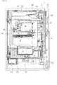
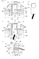
図2に示すように、パチンコ遊技機1の裏面側では、演出表示装置9を制御する演出制御用マイクロコンピュータが搭載された演出制御基板80を含む変動表示ユニット49、遊技制御用マイクロコンピュータ等が搭載された遊技制御基板(主基板)31、音声出力基板70、LEDドライバ基板(図示省略)、および、球払出制御を行なう払出制御用マイクロコンピュータ等が搭載された払出制御基板37等の各種基板が設置されている。
As shown in FIG. 2, on the back side of the pachinko gaming machine 1, there are a
さらに、パチンコ遊技機1裏面側には、DC30V、DC21V、DC12VおよびDC5V等の各種電源電圧を作成する電源回路が搭載された電源基板910やタッチセンサ基板91Aが設けられている。電源基板910は、一部が払出制御基板37と重なっているが、払出制御基板37に重なることなく外部から視認可能に露出した露出部分には、パチンコ遊技機1における主基板31および各電気部品制御基板(演出制御基板80および払出制御基板37)やパチンコ遊技機1に設けられている各電気部品(電力が供給されることによって動作する部品)への電力供給を実行あるいは遮断するための電力供給許可手段としての電源スイッチが設けられている。さらに、露出部分における電源スイッチの内側(基板内部側)には、交換可能なヒューズが設けられている。
Further, on the back side of the pachinko gaming machine 1, a
なお、電気部品制御基板には、電気部品制御用マイクロコンピュータを含む電気部品制御手段が搭載されている。電気部品制御手段は、遊技制御手段等からのコマンドとしての指令信号(制御信号)にしたがってパチンコ遊技機1に設けられている電気部品(遊技用装置:球払出装置97、演出表示装置9、LEDなどの発光体、スピーカ27等)を制御する。
An electrical component control means including an electrical component control microcomputer is mounted on the electrical component control board. The electrical component control means is an electrical component (game device:
パチンコ遊技機1裏面において、上方には、各種情報をパチンコ遊技機1外部に出力するための各端子を備えたターミナル基板159が設置されている。ターミナル基板159には、少なくとも、球切れ検出スイッチ167の出力を導入して外部出力するための球切れ用端子、賞球情報(賞球個数信号)を外部出力するための賞球用端子および球貸し情報(球貸し個数信号)を外部出力するための球貸し用端子が設けられている。また、中央付近には、主基板31からの各種情報をパチンコ遊技機1外部に出力するための各端子を備えた情報端子基板(情報出力基板)36が設置されている。
On the back surface of the pachinko gaming machine 1, a
尚、前記球切れ用端子、賞球情報(賞球個数信号)及び球貸し情報(球貸し個数信号)は、主基板31から情報端子基板36を介して外部に出力するようにしてもよい。すなわち、このようにターミナル基板159に設けられた球切れ用端子、賞球用端子、球貸し用端子を情報端子基板36に設けることで、配線や基板の取り付け作業等を容易にすることができる。また、ターミナル基板159及び情報端子基板36それぞれに設けられる各端子を1つの基板にまとめて搭載してもよく、このようにすることで製造コストを削減することができる。
The ball break terminal, prize ball information (prize ball number signal) and ball rental information (ball rental number signal) may be output from the
図示しない遊技機設置島から供給される球を貯留可能な球タンク38に貯留されたパチンコ球は、タンクレールを通り、カーブ樋を経てケースカバーで覆われた球払出装置97に至る。球払出装置97の上方には、通路内に球がない旨を検出する遊技媒体切れ検出手段としての球切れスイッチ197が設けられている。球切れスイッチ197が球切れを検出すると、球払出装置97の払出動作が停止する。球切れスイッチ197はパチンコ球通路内のパチンコ球の有無を検出するスイッチであるが、球タンク38内の補給球の不足を検出する球切れ検出スイッチ167も誘導レールにおける上流部分(球タンク38に近接する部分)に設けられている。球切れ検出スイッチ167がパチンコ球の不足を検知すると、遊技機設置島に設けられている補給機構からパチンコ遊技機1に対してパチンコ球の補給が行われる。
Pachinko balls stored in a
入賞に基づく景品としてのパチンコ球や球貸し要求に基づくパチンコ球が多数払出されて打球供給皿3が満杯になると、パチンコ球は、余剰球誘導通路を経て余剰球受皿4に導かれる。さらにパチンコ球が払出されると貯留状態検出手段としての満タンスイッチ(図示略)がオンする。その状態では、球払出装置内の払出モータの回転が停止して球払出装置の動作が停止するとともに打球発射装置の駆動も停止する。 When a large number of pachinko balls as prizes based on winning prizes or pachinko balls based on ball lending requests are paid out and the hitting ball supply tray 3 is full, the pachinko balls are guided to the surplus ball receiving tray 4 through the surplus ball guiding passage. Further, when the pachinko ball is paid out, a full tank switch (not shown) as a storage state detecting means is turned on. In this state, the rotation of the payout motor in the ball payout device is stopped, the operation of the ball payout device is stopped, and the driving of the ball hitting device is also stopped.
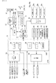
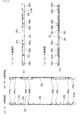
図3は、主基板(遊技制御基板)31における回路構成の一例を示すブロック図である。なお、図3には、払出制御基板37および演出制御基板80等も示されている。主基板31には、プログラムに従ってパチンコ遊技機1を制御する遊技制御用マイクロコンピュータ(遊技制御手段に相当)560が搭載されている。遊技制御用マイクロコンピュータ156は、ゲーム制御(遊技進行制御)用のプログラム等を記憶するROM54、ワークメモリとして使用される記憶手段としてのRAM55、プログラムに従って制御動作を行うCPU56およびI/Oポート部57を含む。この実施例では、ROM54およびRAM55は遊技制御用マイクロコンピュータ156に内蔵されている。すなわち、遊技制御用マイクロコンピュータ156は、1チップマイクロコンピュータである。1チップマイクロコンピュータには、少なくともCPU56のほかRAM55が内蔵されていればよく、ROM54は外付けであっても内蔵されていてもよい。また、I/Oポート部57は、外付けであってもよい。遊技制御用マイクロコンピュータ156には、さらに、ハードウェア乱数(ハードウェア回路が発生する乱数)を発生する乱数回路53が内蔵されている。
FIG. 3 is a block diagram showing an example of the circuit configuration of the main board (game control board) 31. FIG. 3 also shows a
なお、遊技制御用マイクロコンピュータ156においてCPU56がROM54に格納されているプログラムに従って制御を実行するので、以下、遊技制御用マイクロコンピュータ156(またはCPU56)が実行する(または、処理を行う)ということは、具体的には、CPU56がプログラムに従って制御を実行することである。このことは、主基板31以外の他の基板に搭載されているマイクロコンピュータについても同様である。
In the game control microcomputer 156, the
乱数回路53は、特別図柄の可変表示の表示結果により大当りとするか否か判定するための判定用の乱数を発生するために用いられるハードウェア回路である。乱数回路53は、初期値(例えば、0)と上限値(例えば、65535)とが設定された数値範囲内で、数値データを、設定された更新規則に従って更新し、ランダムなタイミングで発生する始動入賞時が数値データの読出(抽出)時であることにもとづいて、読出される数値データが乱数値となる乱数発生機能を有する。
The
乱数回路53は、数値データの更新範囲の選択設定機能(初期値の選択設定機能、および、上限値の選択設定機能)、数値データの更新規則の選択設定機能、および数値データの更新規則の選択切換え機能等の各種の機能を有する。このような機能によって、生成する乱数のランダム性を向上させることができる。
The
また、遊技制御用マイクロコンピュータ156は、乱数回路53が更新する数値データの初期値を設定する機能を有している。例えば、ROM54等の所定の記憶領域に記憶された遊技制御用マイクロコンピュータ156のIDナンバ(遊技制御用マイクロコンピュータ156の各製品ごとに異なる数値で付与されたIDナンバ)を用いて所定の演算を行なって得られた数値データを、乱数回路53が更新する数値データの初期値として設定する。そのような処理を行うことによって、乱数回路53が発生する乱数のランダム性をより向上させることができる。
Further, the game control microcomputer 156 has a function of setting an initial value of numerical data updated by the
遊技制御用マイクロコンピュータ156は、第1始動口スイッチ13aまたは第2始動口スイッチ14aへの始動入賞が生じたときに乱数回路53から数値データをランダムRとして読み出し、特別図柄および演出図柄の変動開始時にランダムRにもとづいて特定の表示結果としての大当り表示結果にするか否か、すなわち、大当りとするか否かを決定する。そして、大当りとすると決定したときに、遊技状態を遊技者にとって有利な特定遊技状態としての大当り遊技状態に移行させる。
The game control microcomputer 156 reads the numerical data as random R from the
また、RAM55は、その一部または全部が電源基板において作成されるバックアップ電源によってバックアップされている不揮発性記憶手段としてのバックアップRAMである。すなわち、遊技機に対する電力供給が停止しても、所定期間(バックアップ電源としてのコンデンサが放電してバックアップ電源が電力供給不能になるまで)は、RAM55の一部または全部の内容は保存される。特に、少なくとも、遊技状態すなわち遊技制御手段の制御状態に応じたデータ(特別図柄プロセスフラグや合算保留記憶数カウンタの値など)と未払出賞球数を示すデータは、バックアップRAMに保存される。遊技制御手段の制御状態に応じたデータとは、停電等が生じた後に復旧した場合に、そのデータにもとづいて、制御状態を停電等の発生前に復旧させるために必要なデータである。また、制御状態に応じたデータと未払出賞球数を示すデータとを遊技の進行状態を示すデータと定義する。なお、この実施例では、RAM55の全部が、電源バックアップされているとする。
The
遊技制御用マイクロコンピュータ156のリセット端子には、電源基板からのリセット信号(図示せず)が入力される。電源基板には、遊技制御用マイクロコンピュータ156等に供給されるリセット信号を生成するリセット回路が搭載されている。なお、リセット信号がハイレベルになると遊技制御用マイクロコンピュータ156等は動作可能状態になり、リセット信号がローレベルになると遊技制御用マイクロコンピュータ156等は動作停止状態になる。従って、リセット信号がハイレベルである期間は、遊技制御用マイクロコンピュータ156等の動作を許容する許容信号が出力されていることになり、リセット信号がローレベルである期間は、遊技制御用マイクロコンピュータ156等の動作を停止させる動作停止信号が出力されていることになる。なお、リセット回路をそれぞれの電気部品制御基板(電気部品を制御するためのマイクロコンピュータが搭載されている基板)に搭載してもよい。 A reset signal (not shown) from the power supply board is input to the reset terminal of the game control microcomputer 156. A reset circuit for generating a reset signal supplied to the game control microcomputer 156 and the like is mounted on the power supply board. When the reset signal becomes high level, the game control microcomputer 156 and the like are in an operable state, and when the reset signal becomes low level, the game control microcomputer 156 and the like become inactive. Therefore, an allowable signal that allows the operation of the game control microcomputer 156 or the like is output during a period in which the reset signal is at a high level, and a game control microcomputer in which the reset signal is at a low level. An operation stop signal for stopping the operation of 156 or the like is output. Note that the reset circuit may be mounted on each electric component control board (a board on which a microcomputer for controlling the electric parts is mounted).
さらに、遊技制御用マイクロコンピュータ156の入力ポートには、電源基板からの電源電圧が所定値以下に低下したことを示す電源断信号が入力される。すなわち、電源基板には、遊技機において使用される所定電圧(例えば、DC30VやDC5Vなど)の電圧値を監視して、電圧値があらかじめ定められた所定値にまで低下すると(電源電圧の低下を検出すると)、その旨を示す電源断信号を出力する電源監視回路が搭載されている。また、遊技制御用マイクロコンピュータ156の入力ポートには、RAMの内容をクリアすることを指示するためのクリアスイッチが操作されたことを示すクリア信号(図示せず)が入力される。 Further, a power-off signal indicating that the power supply voltage from the power supply board has dropped below a predetermined value is input to the input port of the game control microcomputer 156. That is, the power supply board monitors the voltage value of a predetermined voltage (for example, DC30V or DC5V) used in the gaming machine, and when the voltage value decreases to a predetermined value (the power supply voltage is reduced). A power supply monitoring circuit that outputs a power-off signal indicating that). A clear signal (not shown) indicating that a clear switch for instructing to clear the contents of the RAM is operated is input to the input port of the game control microcomputer 156.
また、ゲートスイッチ32a、第1始動口スイッチ13a、第2始動口スイッチ14aおよびカウントスイッチ23からの検出信号を遊技制御用マイクロコンピュータ156に与える入力ドライバ回路58も主基板31に搭載されている。また、可変入賞球装置15を開閉するソレノイド16、および大入賞口を形成する特別可変入賞球装置20を開閉するソレノイド21を遊技制御用マイクロコンピュータ156からの指令に従って駆動する出力回路59も主基板31に搭載されている。さらに、大当り遊技状態の発生を示す大当り情報等の情報出力信号をホールコンピュータ等の外部装置に対して出力する情報出力回路(図示せず)も主基板31に搭載されている。
Further, an
この実施例では、演出制御基板80に搭載されている演出制御手段(演出制御用マイクロコンピュータで構成される。)が、中継基板77を介して遊技制御用マイクロコンピュータ156から演出内容を指示する演出制御コマンドを受信し、演出図柄を可変表示する演出表示装置9との表示制御を行う。
In this embodiment, the effect control means (configured by the effect control microcomputer) mounted on the
演出制御基板80は、演出制御用CPUおよびRAMを含む演出制御用マイクロコンピュータ(図示略)を搭載している。なお、RAMは外付けであってもよい。演出制御基板80において、演出制御用CPU(図示略)は、内蔵または外付けのROM(図示略)に格納されたプログラムに従って動作し、中継基板77を介して入力される主基板31からの取込信号(演出制御INT信号)に応じて、入力ドライバおよび入力ポートを介して演出制御コマンドを受信する。また、演出制御用CPU(図示略)は、演出制御コマンドにもとづいて、VDP(ビデオディスプレイプロセッサ)に演出表示装置9の表示制御を行わせる。
The
演出制御用CPU(図示略)は、受信した演出制御コマンドに従ってキャラクタROM(図示せず)から必要なデータを読み出す。キャラクタROMは、演出表示装置9に表示されるキャラクタ画像データ、具体的には、人物、文字、図形または記号等(演出図柄を含む)をあらかじめ格納しておくためのものである。演出制御用CPU(図示略)は、キャラクタROMから読み出したデータをVDPに出力する。VDPは、演出制御用CPUから入力されたデータにもとづいて表示制御を実行する。
An effect control CPU (not shown) reads necessary data from a character ROM (not shown) in accordance with the received effect control command. The character ROM is for storing character image data displayed on the
演出制御コマンドおよび演出制御INT信号は、演出制御基板80において、まず、入力ドライバに入力する。入力ドライバは、中継基板77から入力された信号を演出制御基板80の内部に向かう方向にしか通過させない(演出制御基板80の内部から中継基板77への方向には信号を通過させない)信号方向規制手段としての単方向性回路でもある。
The effect control command and the effect control INT signal are first input to the input driver on the
中継基板77には、主基板31から入力された信号を演出制御基板80に向かう方向にしか通過させない(演出制御基板80から中継基板77への方向には信号を通過させない)信号方向規制手段としての単方向性回路(図示略)が搭載されている。単方向性回路として、例えばダイオードやトランジスタが使用される。さらに、単方向性回路であるI/Oポート部を介して主基板31から演出制御コマンドおよび演出制御INT信号が出力されるので、中継基板77から主基板31の内部に向かう信号が規制される。すなわち、中継基板77からの信号は主基板31の内部(遊技制御用マイクロコンピュータ156側)に入り込まない。
As a signal direction regulating means, the signal inputted from the
さらに、演出制御用CPU(図示略)は、出力ポート(図示略)を介してランプドライバ基板35に対してLEDを駆動する信号を出力する。また、演出制御用CPUは、出力ポートを介して音声出力基板70に対して音番号データを出力する。
Further, the effect control CPU (not shown) outputs a signal for driving the LED to the
ランプドライバ基板35において、LEDを駆動する信号は、入力ドライバ(図示略)を介してLEDドライバに入力される。LEDドライバは、駆動信号を天枠LED28a、左枠LED28b、右枠LED28cなどの枠側に設けられている各LEDに供給する。また、遊技盤側に設けられている装飾LED25に駆動信号を供給する。なお、LED以外の発光体が設けられている場合には、それを駆動する駆動回路(ドライバ)がランプドライバ基板35に搭載される。
In the
音声出力基板70において、音番号データは、入力ドライバ(図示略)を介して音声合成用IC(図示略)に入力される。音声合成用ICは、音番号データに応じた音声や効果音を発生し増幅回路(図示略)に出力する。増幅回路は、音声合成用ICの出力レベルを、ボリュームで設定されている音量に応じたレベルに増幅した音声信号をスピーカ27R,27Lに出力する。音声データROM(図示略)には、音番号データに応じた制御データが格納されている。音番号データに応じた制御データは、所定期間(例えば演出図柄の変動期間)における効果音または音声の出力態様を時系列的に示すデータの集まりである。
In the
また、演出制御用CPU(図示略)は、入出力ポートを介して操作部50に接続されており、該入出力ポートを介して操作部50内のLED50bを駆動する信号を出力するとともに、操作部50内の操作スイッチ50aから遊技者の押圧操作に応じて出力される操作信号が入力される。
The effect control CPU (not shown) is connected to the
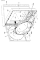
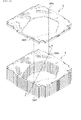
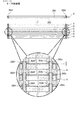
次に、本実施例のパチンコ遊技機1の構造について、図面にもとづいて説明する。図4は、パチンコ遊技機を開放した状態を示す斜視図である。図5は、遊技盤ユニットを示す分解斜視図である。図6は、遊技盤を示す分解斜視図である。図7は、スペーサ部材の前面、左右側面、平面、底面を示す図である。図8は、(a)は図7のA−A断面図であり、(b)は図7のB−B断面図であり、(c)は図7のC−C断面図であり、(d)は図7のD−D断面図である。図9は、スペーサ部材を示す背面図である。図10は、複数の遊技盤を積み重ねた状態を示す斜視図である。図11は、図10のE−E断面図である。 Next, the structure of the pachinko gaming machine 1 according to the present embodiment will be described with reference to the drawings. FIG. 4 is a perspective view showing a state in which the pachinko gaming machine is opened. FIG. 5 is an exploded perspective view showing the game board unit. FIG. 6 is an exploded perspective view showing the game board. FIG. 7 is a diagram illustrating a front surface, left and right side surfaces, a plane surface, and a bottom surface of the spacer member. 8A is a cross-sectional view taken along line AA in FIG. 7, FIG. 8B is a cross-sectional view taken along line BB in FIG. 7, and FIG. 8C is a cross-sectional view taken along line CC in FIG. d) is a DD cross-sectional view of FIG. FIG. 9 is a rear view showing the spacer member. FIG. 10 is a perspective view showing a state in which a plurality of game boards are stacked. 11 is a cross-sectional view taken along line EE in FIG.
図4に示すように、パチンコ遊技機1は、縦長の方形枠状に形成され、遊技場に設置される遊技機設置島(図示略)に固定される外枠100と、外枠100の内側に開閉可能に取り付けられ、遊技盤6を含む遊技盤ユニット400が前面側から取り付けられる合成樹脂製の遊技枠110と、遊技枠110の前面側に開閉可能に設けられる額縁状に形成され、透視窓2aを有するガラス扉枠2と、遊技枠110の背面に、ネジ等の止着部材または係止部材等により着脱自在に取り付けられ、前述した球払出装置97や機構部品等が取り付けられる機構板120と、から主に構成される。尚、機構板120は、遊技枠110の背面側に一側辺を中心に回動可能に設けてもよいし、あるいは外枠100側に取り付けてもよい。
As shown in FIG. 4, the pachinko gaming machine 1 is formed in a vertically long rectangular frame shape, and is fixed to a gaming machine installation island (not shown) installed in the game hall, and the inner side of the
(遊技盤ユニット)
図4に示すように、遊技枠110の前面上部には、遊技盤ユニット400が取り付けられる取付部111が形成されており、該取付部111には、遊技盤ユニット400における後述するカバー体302(図5参照)の後部が嵌合される開口部112が形成されているとともに、機構板120における該開口部112に対応する箇所も開設されている。遊技盤ユニット400は、遊技盤ユニット400と遊技枠110との間に設けられる図示しない係止手段等を介して、遊技枠110に対して前面側から着脱自在に取り付けできるようになっている。
(Game board unit)
As shown in FIG. 4, an
遊技枠110における開口部112の下方には、打球操作ハンドル5の上部に設けられる図示しない打球発射装置にて発射される遊技球を、遊技盤6に向けて誘導する発射球誘導レール500cが配設されている。打球発射装置は、特に詳細な図示はしないが、発射球誘導レール500cの右側の下端部に設けられる打球発射位置に配置された遊技球を遊技盤6に向けて打ち出す打球部材(ハンマー等)と、該打球部材を揺動させるための電気的駆動源(モータ等)と、を一体的にユニット化したもの等で構成されている。また、発射球誘導レール500cは、帯状の金属板からなり、遊技枠110の前面110aに対して、該前面110a側の縁辺部Hを当接させた状態で取り付けられている。
Below the
発射球誘導レール500cは、ガラス扉枠2を閉鎖しても透視窓2aを通して視認できない位置に配置されており、ガラス扉枠2の下方に設けられた開閉扉により前面が被覆されるため、使用状態において遊技者側から視認されることはない。よって、遊技球が発射球誘導レール500cに沿って誘導され、それにより生じる振動により発射球誘導レール500cの前面110a側の縁辺部Hと前面110aとが擦れて削られた粉が前面に付着しても目立たないので、発射球誘導レール500cの前面110a側の縁辺部Hを前面110aに当接させて強固に取り付けている。
The firing
図5に示すように、遊技盤ユニット400は、遊技盤6と、該遊技盤6の背面側に配置され、遊技盤6を背面側から装飾する装飾体301と、該装飾体301を遊技盤6に対して取り付けるためのカバー体302と、装飾体301の背面に取り付けられ、演出表示装置9及び演出制御基板80等を含む変動表示ユニット49と、から主に構成されている。
As shown in FIG. 5, the
装飾体301は、後述するように透明に形成される遊技盤6の遊技領域7を背面側から装飾する立体状に形成された装飾体であり、前後方向に所定幅の肉厚を有している。装飾体301の前面は、特に詳細な図示はしないが、非平坦面状に形成され、奥行き感のある装飾部が形成されている。また、遊技盤6側に設けられる各種表示装置(例えば第1特別図柄表示器8a、第2特別図柄表示器8b等)、駆動手段(ソレノイド16,21等)、LED、各種スイッチ(例えばゲートスイッチ32a、第1始動口スイッチ13a、第2始動口スイッチ13b、カウントスイッチ23等)から延出される配線は、遊技盤6の背面と装飾体301の前面との間から側方に引き出されるため、これら配線は、装飾部と同色または同系色に着色され、これにより配線が目立たないようにしている。
The
また、装飾体301の略中央位置には、背面側に配設される演出表示装置9の表示面を視認可能とするための開口部303が形成されているとともに、その周辺には、遊技領域7に配設される各種入賞口(例えば第1始動入賞口13や第2始動入賞口14等)に入賞した遊技球を背面側に排出するための遊技球排出口(図示略)が複数形成されている。さらに装飾体301には、特に図示はしないが、駆動手段等により可動自在に設けられる演出用の可動物や、LEDやランプ等の装飾用発光体が設けられる。このように構成された装飾体301は、背面側のカバー体302に前面側から組み付けられる。
In addition, an
尚、本実施例の装飾体301は、所定肉厚を有する一つの板状体にて構成されていたが、形状は種々に変形可能であるとともに、それぞれ個別に形成された複数の装飾体であってもよい。
Although the
カバー体302は、透明な合成樹脂材からなり、前面が開口する箱状に形成された本体部311内に、装飾体301を前面側から収容可能に形成されている。本体部311の前面開口の周縁部からは、遊技盤6に取り付けるためのフランジ片310が外向きに形成されており、該フランジ片310の前面側には、遊技盤6に対する当該カバー体302の取付位置を決定するための複数の位置決め用ボス312a〜312d(図34参照)が前面側に向けて突設されているとともに、遊技盤6に当該カバー体302を取り付けるための取付ネジ313が取り付けられる取付穴314が複数箇所に形成されている。
The
本体部311の背板311aには、当該背板311aの背面側に組み付けられる演出表示装置9の表示面を視認可能とするための開口部315が形成されている。演出表示装置9を含む変動表示ユニット49は、背板311aの背面側から演出表示装置9の表示面を開口部315に臨ませるように背板311aの背面に取り付けられる。尚、変動表示ユニット49は、装飾体301の背面に直接取り付けてもよい。
An
カバー体302には、これら装飾体301、変動表示ユニット49だけでなく、他の装置や基板等が組み付け可能とされており、カバー体302及び該カバー体302に一体的に組み付けられる装飾体301、変動表示ユニット49等を含む遊技に関連する複数の遊技用部品により、遊技用部品ユニット300が構成される。このように構成される遊技用部品ユニット300は、遊技盤6に対して着脱可能に取り付けられ、複数の機種に共通して使用される機種共通部品であるカバー体302に、機種固有の装飾体301や変動表示ユニット49等の各種遊技用部品を着脱可能に組み付けることができるため、遊技盤6の背面側に配設される複数の遊技用部品を、カバー体302を取り付けるだけで一度に配設することができるばかりか、機種変更やメンテナンスの際には、カバー体302から機種固有の装飾体や遊技用部品を取り外すことができるため、作業性が向上する。
In addition to the
(遊技盤)
図6及び図7に示すように、遊技盤6は、アクリル樹脂、ポリカーボネート樹脂、メタクリル樹脂等の透明な合成樹脂材にて形成される合成樹脂板200と、該合成樹脂板200の背面側に一体的に取り付けられるスペーサ部材250と、から主に構成される。合成樹脂板200の厚さは約1cm程度であり、全体が透明に形成されている。尚、本実施例では合成樹脂板200全体が透明に形成されているが、当該合成樹脂板200の前面側からその背面側に配設される装飾体301を透視可能な透光性を有していれば、半透明であってもよいし、着色されていてもよい。また、全体が透光性を有していなくても、少なくとも遊技領域7の一部に透光部が形成されていればよい。
(Game board)
As shown in FIGS. 6 and 7, the
合成樹脂板200には、背面側に配設される演出表示装置9の表示面を前面側に臨ませるとともに、センター枠飾り11(図1参照)が取り付けられる取付穴201と、可変入賞球装置15(図1参照)が取り付けられる取付穴202と、特別可変入賞球装置20(図1参照)が取り付けられる取付穴203と、アウト口26(図1参照)を形成するアウト口穴204と、ゲート32(図1参照)が取り付けられる取付穴205と、装飾LED25aを有する装飾部材25L(図1参照)が取り付けられる取付穴206aと、装飾LED25bを有する装飾部材25R(図1参照)が取り付けられる取付穴206bと、がそれぞれ前後方向に貫通して形成されている。
The
各取付穴201〜206の周囲前面には、各部材を取り付けるためのネジが螺入されるネジ穴TAが複数箇所に形成されているとともに、後述する外レール500aや内レール500bが取り付けられる取付穴TBが複数箇所に形成されている。
Screw holes TA into which screws for attaching each member are screwed are formed at a plurality of locations on the front surface around each of the attachment holes 201 to 206, and an
また、合成樹脂板200の周囲には、スペーサ部材250から前面側に突設され、後述する外レール飾り600a〜600cを取り付けるための取付ネジが取り付けられるネジ穴が先端に形成された複数の取付用ボス260a〜260h及びスペーサ部材250から前面側に突設され、後述する証紙貼付部材601を取り付けるための取付ネジが取り付けられるネジ穴が先端に形成された取付用ボス260jがそれぞれ挿通される挿通穴207a〜207jが、それぞれ対応した位置に前後方向に貫通して形成されている。
Further, a plurality of attachments are formed around the
また、合成樹脂板200を前面側から見たときにおける左上部、左下部、右上部には、スペーサ部材250から前面側に突設される複数の位置決め用ボス261a〜261cがそれぞれ嵌合される位置決め穴208a〜208cが、それぞれ対応した位置に前後方向に貫通して形成されている。尚、これら以外にも、複数の挿通穴や取付穴等が形成されている。
A plurality of
また、合成樹脂板200の側面における四隅近傍位置には、スペーサ部材250に形成された弾性係止爪270a〜270dがそれぞれ係止される係止段部220a〜220dがそれぞれ形成されている。係止段部220a〜220dは、合成樹脂板200の側面における前面側の縁辺部Hに切欠形成される(図19参照)。
Further, locking
スペーサ部材250は、外形が合成樹脂板200と同様に形成された板状部材の中央に、合成樹脂板200の前面に略円形に形成される遊技領域7とほぼ同形の開口部251が形成されることにより枠状に形成されている。
The
詳しくは、図6〜図9に示すように、スペーサ部材250は、背板252と、該背板252の周縁から前面側に向けて立設された側壁253と、背板252の開口部251の周縁から前面側に向けて立設される円形状リブ254と、背板252の前面側における該円形状リブ254と背板252とに囲まれた領域に格子状に立設されるリブ255と、により構成されている。円形状リブ254及びリブ255の高さ幅寸法(前後幅寸法)は約1cmで、側壁253の高さ幅寸法(前後幅寸法、約2cm)の約半分とされており、これら円形状リブ254及びリブ255の前端面上に合成樹脂板200が当接するように組み付けられる。そして組み付けられた合成樹脂板200の側周面の外側に側壁253が配置されて該側壁253により被覆され、接触や落下による損傷から保護されるようになっている。
Specifically, as shown in FIGS. 6 to 9, the
側壁253の四隅近傍には、合成樹脂板200の側周面に形成された係止段部220a〜220dに弾性的に係止される弾性係止爪270a〜270dが、前端部から切り溝を切り込むことにより形成されている。
In the vicinity of the four corners of the
図7及び図8に示すように、背板252の前面側には、前述した取付用ボス260a〜260h,260jと、位置決め用ボス261a〜261cとが、それぞれリブ255の交差位から前面側に向けて突設されている。これら取付用ボス260a〜260h,260j及び位置決め用ボス261a〜261cは、側壁253の前端部より若干前面側に突出する長さを有している。そして特に取付用ボス260c、260fに関しては、他の取付用ボス260a,260b、260d〜260h,260j及び位置決め用ボス261a〜261cよりも若干長めに形成されており、後述するように組み付けられた合成樹脂板200の遊技盤面200aよりも前面側に突出するようになっている。
As shown in FIGS. 7 and 8, the mounting
このように構成されたスペーサ部材250の前面側に合成樹脂板200を嵌合すると、合成樹脂板200に形成された各位置決め穴208a〜208c内に位置決め用ボス261a〜261cが背面側から嵌合され、スペーサ部材250に対する合成樹脂板200の組み付け位置が決定されるとともに、各挿通穴207a〜207h,207j内に取付用ボス260a〜260h,260jがそれぞれ挿通され、各挿通穴207a〜207h,207jの先端に形成されたネジ穴が、合成樹脂板200の遊技盤面200a側に臨むことになる。
When the
また、合成樹脂板200の背面が円形状リブ254及びリブ255の前端面上に当接されると、各弾性係止爪270a〜270dが各係止段部220a〜220dに弾性的に係止され、スペーサ部材250からの合成樹脂板200の離脱が規制される。このように各弾性係止爪270a〜270dが各係止段部220a〜220dに弾性的に係止された状態において、各弾性係止爪270a〜270dの先端は、合成樹脂板200の遊技盤面200aよりも前面側に突出しないようになっている(図19参照)。つまり、各弾性係止爪270a〜270dを含む側壁253の前端部は、組み付けられた合成樹脂板200の遊技盤面200aよりも前面側に突出しない長さに形成されているため、合成樹脂板200の遊技盤面200aよりも前面側に突出して、後述する製造時や保管、搬送時等において各弾性係止爪270a〜270dが床面や他の遊技盤6等と接触して破損することが防止される。
Further, when the back surface of the
また、各位置決め穴208a〜208c内に嵌合された位置決め用ボス261a〜261c及び各挿通穴207a〜207h,207j内に挿通された取付用ボス260a,260b、260d〜260h,260jは、合成樹脂板200の遊技盤面200aよりも前面側に突出しないが、取付用ボス260c、260fに関しては、合成樹脂板200の遊技盤面200aよりも約5mmほど前面側に突出する。
The
図9に示すように、背板252における開口部251の下部には、アウト口穴204に連通するアウト開口部262が形成されている。背板252の前面側におけるアウト開口部262の周縁にもアウト口リブ263(図6、図7参照)が立設され、その前端面が合成樹脂板200の背面200bにおけるアウト口穴204の周縁に当接するようになっており、これにより前後方向に所定幅寸法を有するアウト開口部262を構成している。
As shown in FIG. 9, an
背板252の背面における取付用ボス260c、260fに対応する箇所には、該取付用ボス260c、260fの先端がそれぞれ嵌合可能な円形状の嵌合凹部264c、264f(図11中拡大図参照)が凹設されており、図11に示すように複数の遊技盤6を上下方向に積み重ねたときに、下方の遊技盤6の取付用ボス260c、260fが嵌合凹部264c、264fに嵌合されるようになっている。
Circular fitting recesses 264c and 264f into which the tips of the mounting
背板252における開口部251の上部左右側及び下部左右側には、前述したカバー体302に設けられた位置決め用ボス312a〜312dが嵌合可能な円形状のカバー体用位置決め穴265a〜265dが形成されている。これらカバー体用位置決め穴265a〜265dのうち、背面側から見て右上及び右下のカバー体用位置決め穴265a,265dは、背面側から見て左上及び左下のカバー体用位置決め穴265b,265cに比べて、直径が大径とされているとともに、上下の側壁253寄りに配置されている。
Circular cover
また、各カバー体用位置決め穴265a〜265dからは、開口部251の周縁まで延びる案内凹溝266a〜266d(図31、図32参照)が上下方向に向けて凹設されている。これら案内凹溝266a〜266dは、カバー体用位置決め穴265a〜265dから開口部251の周縁に向けて漸次幅広となるように形成されており、案内凹溝266a〜266dにおける幅広部に位置決め用ボス312a〜312dの先端を載置した後、カバー体用位置決め穴265a〜265dに向けて位置決め用ボス312a〜312dの先端を滑らせることで、カバー体用位置決め穴265a〜265dに容易に嵌合できるようになっている。
In addition, guide
また、背板252の背面における開口部251の周縁部には、後述する外レール飾り600a〜600cのリブの先端が係合する係合段部267が、開口部251の周縁部に沿って延設されている。
In addition, an
ここで、このように構成される遊技盤6の製造工程について簡単に説明すると、合成樹脂に熱を加えて溶かした樹脂を金型に流し込んで合成樹脂板200の原板を形成した後、所定の加工装置を用いて原板を切削して所定の形状に加工する。一方、スペーサ部材250を成型し、これら合成樹脂板200とスペーサ部材250とを一体的に組み付けて遊技盤6を構成する。
Here, the manufacturing process of the
次いで、合成樹脂板200の表面に障害釘や各種入賞装置等の取付穴等を開設した後、釘打機まで搬送して障害釘を打設する。これらの加工は、例えば遊技盤を搬送コンベア上に載置して搬送する際に順次行われていく。そして取付穴等の加工機を通して釘打機まで移送する際には、次の加工工程で待機させる際に場所をとらないようにするために、複数枚の本体板を積み重ねて効率よく搬送コンベアにて搬送する。
Next, after opening a mounting hole or the like for a failure nail or various prize winning devices on the surface of the
また、釘打ち加工後に後述する打球レールや小型の入賞装置等を取り付けた後、大型の入賞装置や制御回路基板等の大型部品を取り付けるが、組付工程が煩雑化することから組付速度が低下するため、釘打ち及び小型の入賞装置を取り付けた後に、遊技盤を積み重ねて待機することがある。 In addition, after attaching a ball rail or a small winning device to be described later after nailing, large components such as a large winning device and a control circuit board are attached, but the assembly process is complicated and the assembly speed is increased. Therefore, the game board may be stacked and waited after the nailing and the small winning device is attached.
このように、遊技盤6を取付穴等の加工機を通して釘打機まで移送する際には、次の加工工程で待機させる際に場所をとらないようにするために、複数枚の本体板を積み重ねて搬送したり、積み重ねた状態で待機することがある(図10参照)。
As described above, when the
図10に示すように、合成樹脂板200の遊技盤面200aに、障害釘や各種入賞装置等を取り付けていない状態において、遊技盤6は上下方向に積み重ねることができる。このように遊技盤6を積み重ねた場合、一の遊技盤6の前面とその上方に積み重ねられた他の遊技盤6の背面とが当接するが、合成樹脂板200及びスペーサ部材250は合成樹脂材にて形成されているため、上方に積載された遊技盤6が滑落しやすい。
As shown in FIG. 10, the
しかし、図11に示すように、下方の遊技盤6の合成樹脂板200の遊技盤面200aから突出した取付用ボス260c、260fの先端が、上方の遊技盤6のスペーサ部材250の背面に形成された嵌合凹部264c、264fに嵌合されることで、下方の遊技盤6に対する上方の遊技盤6の横滑りが規制されて滑落が防止されるとともに、積載位置が決定されるため、図のように複数の遊技盤6を上下方向に積み重ねることができる。
However, as shown in FIG. 11, the tips of the mounting
また、遊技盤6は、厚さ約1cmの合成樹脂板200をスペーサ部材250に一体的に組み付けることで、従来のようにベニヤ合板からなる遊技盤と同じ形状及び同じ肉厚(約2cm)に形成されるため、ベニヤ合板からなる遊技盤を製造する製造ラインを使用して、取付穴や釘打ちの加工を施すことができる。
In addition, the
このようにアクリル樹脂材からなる合成樹脂板200とスペーサ部材250とを組み合わせることにより所定の肉厚の遊技盤6を構成することで、合成樹脂板200のみで所定の肉厚の遊技盤6を形成する場合に比べて、製造コストを低減できるばかりか、軽量の遊技盤を構成することができる。また、スペーサ部材250により透明な合成樹脂板200の背面側が保護されるので、製造時や搬送時における合成樹脂板200の損傷や破損が防止される。
In this way, by combining the
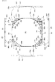
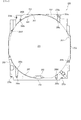
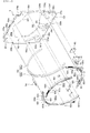
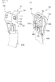
次に、合成樹脂板200の前面に各種部材が取り付けられた遊技盤6の構造について、図12〜図28にもとづいて説明する。図12は、遊技盤の前面側に対する各種部材の取り付け状況を示す斜視図である。図13は、遊技盤の前面に各種部材が取り付けられた状態を示す正面図である。図14は、球戻り防止装置を示す斜視図である。図15は、球戻り防止装置の内部構造を示す分解斜視図である。図16は、(a)は球戻り防止装置を示す側面図であり、(b)は球戻り防止装置の内部構造を示す部分破断図である。図17は、球戻り防止装置を内レールに取り付けた状態を示す図である。図18は、(a)は図17のP−P断面図であり、(b)は(a)のQ−Q断面図である。図19は、図13のF−F断面図である。図20は、図13のG−G断面図である。図21は、図13のH−H断面図である。図22は、図13のJ−J断面図である。図23は、図13のK−K断面図である。図24は、図13のL−L断面図である。図25は、図13のM−M断面図である。図26は、(a)(b)は図13のN−N断面図であり、(c)は(b)のN’−N’断面図であり、(d)はゲートスイッチの本体を示す図である。図27は、遊技部材の遊技盤面への取付構造の変形例を示す断面図である。図28は、外レール飾りの遊技盤面への取付構造を示す断面図である。
Next, the structure of the
遊技盤6における合成樹脂板200の遊技盤面200aには、図12及び図13に示すように、打球発射装置から発射された遊技球を遊技領域7内に外レール500a及び内レール500bからなる打球レール500、外レール飾り600a〜600c、障害釘、風車、証紙貼付部材601、球戻り防止装置700等が取り付けられるとともに、センター枠飾り11、可変入賞球装置15、特別可変入賞球装置20、ゲート32、装飾部材25L,25R等が各取付穴201〜206に前面側から取り付けられる。
On the
(打球レール)
打球レール500は、遊技盤6を前面側から見て、該合成樹脂板200の遊技盤面200aの下部から略円形に形成される遊技領域7の左側周縁に沿って円弧状に配設される外レール500aと、外レール500aの内側に離間して配設される内レール500bとからなり、これら外レール500aと内レール500bとの間に、打球発射装置により発射された遊技球を遊技領域7に誘導する誘導通路502を構成する。
(Hitball rail)
The
打球レール500は、帯状の金属板から構成され、遊技盤面200a側の縁辺部Hに長手方向に向けて所定間隔おきに固設された複数の取付ピン501(図17参照)を遊技盤面200aに形成された複数の取付穴TBに圧入することにより、縁辺部Hと遊技盤面200aとの間に隙間を設けて取り付けられる(図20参照)。このように縁辺部Hと遊技盤面200aとの間に隙間を設けて取り付けることで、打球レール500の側面に遊技球が接触することにより振動が生じても、縁辺部Hと遊技盤面200aとが擦れることがないので、遊技盤面200aが削れることにより生じた粉が遊技盤面200aに付着して遊技盤面200aが汚れたりする可能性が低い。
The hitting
尚、打球レール500における遊技盤面200a側の縁辺部Hとは、打球レール500における遊技盤面200aと対向する対向面(後端面)の外周の辺部であり、反対側の端面(前端面)の周縁辺は含まない。
Note that the edge H on the
また、外レール500aと内レール500bとは、遊技球の直径よりも若干大寸の幅寸法離間されていることで、誘導通路502を移動する遊技球は、外レール500aまたは内レール500bにおける誘導通路502に臨む側面(立設面)を滑るまたは転動するように接触することが多く、該側面上に遊技球が落下して打球レール500に大きな振動が生じることは少ないため、少なくとも球戻り防止装置700が取り付けられる端部側において遊技盤面200aと縁辺部Hとの間に隙間が形成されていれば縁辺部Hと遊技盤面200aとが擦れることがないので、遊技盤面200aが削れることにより生じた粉が遊技盤面200aに付着して遊技盤面200aが汚れたりする可能性が低い。
In addition, the
(外レール飾り)
図12に示すように、外レール飾り600a〜600cは、遊技領域7の左側縁に沿って遊技球の誘導面601aが形成される外レール飾り600aと、遊技領域7の上側縁から右側縁中央部に沿って遊技球の誘導面601bが形成される外レール飾り600bと、遊技領域7の右側縁中央部から下側縁に沿って遊技球の誘導面601cが形成される外レール飾り600cと、を含む。
(Outer rail decoration)
As shown in FIG. 12, the
外レール飾り600aは、取付用ボス260a〜260dの先端に形成されたネジ穴に取付ネジ602a〜602dをそれぞれ螺入することで取り付けられ、外レール飾り600bは、取付用ボス260e,260fの先端に形成されたネジ穴に取付ネジ602e,602fを螺入することで取り付けられ、外レール飾り600cは、取付用ボス260g,260hの先端に形成されたネジ穴に取付ネジ602g,602hを螺入することで取り付けられる。
The
これら外レール飾り600a〜600cは、遊技盤面200a上に立設される立体円弧状の本体部603を有し、該本体部603の内壁603aの外面に誘導面601a〜601cが形成されているとともに、内壁603bの前端部604は、本体部603の前面よりも前面側に突出している(図20〜図23参照)。
These
図20〜図23に示すように、内壁603aにおける遊技盤面200a側の縁辺部Hのうち誘導面601a〜601c側の縁辺部Hには切欠凹溝KMが形成され、遊技盤面200aとの間に隙間(例えば、高さ約0.3mm、幅約2mm(例えば図20参照))が長手方向に向けて延設されている。このように内壁603aの後端面における誘導面601a〜601c側の縁辺部Hに形成された切欠凹溝KMにより、縁辺部Hと遊技盤面200aとの間に隙間が形成され、誘導面601a〜601cに遊技球が接触することにより内壁603aに振動が生じても、縁辺部Hと遊技盤面200aとが擦れることがないので、遊技盤面200aが削れることにより生じた粉が遊技盤面200aに付着して遊技盤面200aが汚れることがない。
As shown in FIGS. 20 to 23, a notch groove KM is formed in the edge portion H on the
尚、外レール飾り600a〜600cそれぞれの内壁603aにおける遊技盤面200a側の縁辺部Hとは、内壁603aにおける遊技盤面200aと対向する対向面(後端面)の外周の辺部であり、反対側の端面(前端面)の周縁辺は含まない。つまり、内壁603aの後端面における切欠凹溝KM以外の部分や、本体部610における内壁603a以外の後端面は遊技盤面200aに当接している。
The edge H on the
また、外レール飾り600bは図20〜図23に図示されていないが、外レール飾り600a,600cと同様に内壁603aにおける遊技盤面200a側の縁辺部Hに切欠凹溝KMが形成されているため、誘導面601bに遊技球が接触することにより内壁603aに振動が生じても、縁辺部Hと遊技盤面200aとが擦れることがないので、遊技盤面200aが削れることにより生じた粉が遊技盤面200aに付着して遊技盤面200aが汚れることがない。
Although the
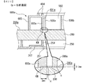
外レール飾り600cは、図12及び図22に示すように、合成樹脂板200のアウト口穴204及びスペーサ部材250のアウト開口部262内に前面側から嵌合される筒状部605が、誘導面601cにおける最下位置から背面側に向けて連設されている。このように誘導面601cにより外レール飾り600cに一体形成された筒状部605に向けて誘導(流下)された遊技球が、該筒状部605の前面開口となるアウト口26内に誘導されて遊技盤6の背面側に排出されるようになっている(図22参照)。
As shown in FIGS. 12 and 22, the
また、図13、図22及び図23に示すように、外レール飾り600cの誘導面601cにおけるアウト口26の近傍位置は、遊技領域7の下部位置に上向きに配設されており、誘導面601cに沿って遊技球を転動により誘導するだけでなく、上方から流下してくる遊技球が直接落下される頻度が高い部位であり、遊技球の落下による衝撃により振動しやすい。よって、外レール飾り600cに一体形成された筒状部605を合成樹脂板200のアウト口穴204及びスペーサ部材250のアウト開口部262内に前面側から嵌合することで、外レール飾り600cが遊技盤面200aに対して強固に取り付けられ、振動の発生が抑制されるため、内壁603aにおける遊技盤面200a側の縁辺部Hと遊技盤面200aとが擦れにくくなり、遊技盤面200aが削れて粉が生じにくくなる。
Further, as shown in FIGS. 13, 22 and 23, the position near the
図28には、外レール飾り600aの遊技盤面200aへの取付構造が示されている。外レール飾り600aは、取付ネジ602a〜602dを取付用ボス260a〜260dの先端に形成されたネジ穴に螺入することで、遊技盤面200aに取り付けられるとともに、背面側に突設された位置決めピン660を、合成樹脂板200に貫通形成された位置決め穴209に前面側から嵌合することで、取付位置を決定できるようになっている。
FIG. 28 shows a structure for attaching the
このように外レール飾り600aは、スペーサ部材250に形成された取付用ボス260a〜260dの先端に取り付けられることで、合成樹脂板200に取付ネジ602a〜602dを直接螺入することにより削られた粉が周囲に付着して遊技盤面200aが汚れること等がない。また、外レール飾り600aとスペーサ部材250とで合成樹脂板200が挟持されるため、合成樹脂板200とスペーサ部材250とを別個のネジ部材等を使用しなくても、外レール飾り600aを取り付けるための取付ネジ602a〜602dにより一体的に組み付けることができる。
As described above, the
尚、外レール飾り600b,600cは外レール飾り600aと同様の取付構造にてスペーサ部材250に取り付けられているため、取付構造の詳細な説明は省略するものとする。
Since the
また、外レール飾り600a,600bに関しては、取付ネジ602c,602fを取り付けるネジ穴が形成された取付用ボス260c、260fが遊技盤面200aよりも前面側に突出しているため、該突出部を利用して遊技盤面200aに対する外レール飾り600a,600bの取付位置を決定することができる。
Further, regarding the
また、外レール飾り600a〜600cの位置決めピン660が前面側から嵌合される位置決め穴209の背面側からは、スペーサ部材250側の位置決めピン661が嵌合されるようにしてもよく、このようにすることで、位置決め穴を外レール飾り600a〜600cとスペーサ部材250との間で共用することができるため、それぞれの位置決め穴を別個に形成する場合に比べて合成樹脂板200の強度低下を防止できるばかりか、穴あけ加工の手間を省くことができる。
Further, the
(球戻り防止装置700)
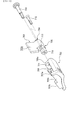
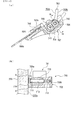
次に、図14〜図18にもとづいて、球戻り防止装置700の構造を説明する。
(Ball return prevention device 700)
Next, the structure of the ball
図14〜図16に示すように、球戻り防止装置700は、誘導通路502と遊技領域7とを連絡する連絡部503(図13参照)を開閉可能に設けられる板状の開閉部701と、内レール500bの下流側端部(図13中における内レール500bの上端部)、つまり誘導通路502の出口付近である連絡部503側の端部に取り付けられ、開閉部701を揺動可能に支持する取付支持部702と、から主に構成される。
As shown in FIGS. 14 to 16, the ball
開閉部701は、打球発射装置から発射された遊技球が当接する発射球当接面703aと、該発射球当接面703aの反対側面であって、遊技領域7から誘導通路502側に向けて戻る遊技球が当接する戻り球当接面703bを有する板状の当接部703と、揺動軸部704と、揺動軸部704を挟んで当接部703の反対側に配置され、連絡部503を閉鎖する閉鎖位置に向けて当接部703を付勢するための錘部705と、から構成される。
The opening /
取付支持部702における誘導通路502側の面には、開閉部701の揺動軸部704及び錘部705を収容可能な凹部706が凹設されている。また、凹部706の側方には、内レール500bの連絡部503側の端部が差し込まれる一対の差込片707a,707bと、差込片707a,707bに差し込まれた内レール500bの端部に形成された係合穴504に弾性係合可能な弾性係合部708が形成されている。
A
凹部706の両側には、取付時において合成樹脂板200の遊技盤面200aに対向して配置される壁部709aと、反対側の壁部709bと、が形成されており、壁部709aには、開閉部701の揺動軸710を外側から挿通可能とする挿通穴711が形成されるとともに、壁部709bの内側には、挿通穴711から開閉部701の揺動軸部704に形成された軸穴713に挿通された揺動軸710の先端に形成された雄ネジ部が螺入されるネジ穴712が形成されている。尚、揺動軸710はネジ部材ではなくピン部材であってもよい。
On both sides of the
また、開閉部701の錘部705には、当該パチンコ遊技機1の組み付け等において使用される汎用のネジ部材715が螺入可能なネジ収容穴714が、軸穴713と平行に形成されており、該ネジ収容穴714にネジ部材715が螺入されることで、重心が錘部705側に偏るようになっている。このように特別な部品等を用いたり、開閉部701を特殊な方法で成型することなく、当該パチンコ遊技機1の組み付け等において使用される汎用のネジ部材715をネジ収容穴714に螺入するだけで錘部705側に重心を偏らせることができるので、開閉部701を容易に形成することができるばかりか、製造コストの低減化を図ることができる。
In addition, a
また、壁部709aの外面における挿通穴711の周縁部には、略C字形の突条716が突設されており、取付時において遊技盤面200aと当接するようになっている。
Further, a substantially C-shaped
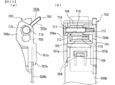
このように構成される球戻り防止装置700は、図17及び図18に示すように、内レール500bの端部を差込片707a,707bに差し込むことで、内レール500bに取り付けられる。本実施例の内レール500bは、各取付ピン501を遊技盤面200aに形成された各取付穴TBに圧入することで遊技盤面200aに取り付けるため、取り付けの際には、内レール500bにおける各取付ピン501近傍を図示しない挟持器具等にて挟持して各取付ピン501を各取付穴TBに圧入する必要がある。
As shown in FIGS. 17 and 18, the ball
そして図17に示すように、内レール500bにおける球戻り防止装置700が取り付けられる側の端部近傍には、該球戻り防止装置700のパチンコ球との当接による衝撃により揺動しないように取付ピン501が設けられているため、該取付ピン501を取付穴TBに圧入するために内レール500bの端部を挟持器具にて挟持する場合、該端部に取り付けた球戻り防止装置700を挟持すると該球戻り防止装置700が破損してしまうため、内レール500bを遊技盤面200aに取り付けた後に球戻り防止装置700を取り付ける必要がある。
Then, as shown in FIG. 17, the
遊技盤面200aに取り付けられた内レール500bの端部に球戻り防止装置700を取り付けるには、突条716を遊技盤面200aに対向させた状態で差込片707a,707bに内レール500bの端部を差し込めばよい。
In order to attach the ball
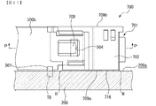
そして内レール500bの端部に差込片707a,707bを差し込むことで、弾性係合部708が係合穴504に弾性係合して抜脱方向への移動が規制されるため、内レール500bの端部が取付ピン501により遊技盤面200a上に強固に取り付けられている状態でも、該内レール500bの端部に差込片707a,707bを差し込むだけの簡単な作業で取付支持部702を取り付けることができる。このように、内レール500bを遊技盤面200aに固定した状態でも、弾性係合部708を係合穴504に弾性係合させるだけで該内レール500bに対して取付支持部702を簡単に取り付けることができるため、内レール500bを遊技盤面200aに固定する際に球戻り防止装置700が邪魔になったり、該球戻り防止装置700が破損されることを防止できる。
Then, by inserting the
また、内レール500bの端部に取付支持部702を取り付けた状態で取付ピン501を取付穴TBに圧入できるようにするために取付ピン501を内レール500bの端部から離れた位置に配置して、球戻り防止装置700が遊技球と接触することにより内レール500bの端部が振動しやすくなることがない。
Further, the mounting
また、内レール500bの端部に取り付けられた状態において、取付支持部702における遊技盤面200a側の縁辺部Hを含め、遊技盤面200aに対向する壁部709aの外面全域が遊技盤面200aに当接することなく、取付支持部702における遊技盤面200a側の縁辺部Hよりも内側に形成された突条716の先端面のみが遊技盤面200aに当接するので、遊技球との当接による衝撃や開閉部701の揺動により取付支持部702に振動が生じ、これにより突条716の先端面と遊技盤面200aとが擦れて遊技盤面200aが削れることにより生じた粉が遊技盤面200aに付着しても、壁部709aにより突条716の周囲が覆われていることで粉が隠蔽されるため、遊技盤面200aの汚れが目立つことがない。
In addition, in the state where it is attached to the end portion of the
尚、取付支持部702における遊技盤面200a側の縁辺部Hとは、取付支持部702における遊技盤面200aと対向する対向面(壁部709aの外面)の外周の辺部であり、反対側の面(壁部709bの外面)の周縁辺は含まない。
The edge portion H on the
また、突条716は揺動軸710の周囲に形成されていることで、取付支持部702が安定して支持されるばかりか、開閉部701の揺動により取付支持部702に対して揺動軸710周りに回動する方向の振動が生じても、突条716は揺動軸710周りに回動するだけで、遊技盤面200a上をスライド移動することはないので、突条716と遊技盤面200aとが擦れて削れた粉が周囲に飛散しにくい。
Further, since the
(装飾部材)
装飾部材25L,25Rは、取付穴206a,206bに取り付けられる。尚、装飾部材25L,25Rは外観形状が異なるものの内部構造はほぼ同様であるため、以下においては装飾部材25Lの構造のみ説明し、装飾部材25Rの構造は省略する。図21に示すように、装飾部材25Lは、遊技盤面200a上に遊技球の流下の障害となりうるように立設される立体状の本体部610と、本体部610の底面から取付穴206aに嵌合される嵌合部611と、から主に構成される。本体部610には、前述したように装飾LED25aが取り付けられるとともに、前面には装飾部が形成されている。
(Decorative member)
The
本体部610は、嵌合部611よりも若干大きく形成され、嵌合部611を取付穴206aに嵌合した状態において、本体部610における嵌合部611の周縁部611aが遊技盤面200aにおける取付穴206aの周縁に配置され、周縁部611aを取付ネジ613にて取り付けできるようになっている。また、周縁部611aの縁辺部H、すなわち、本体部610における遊技盤面200a側の縁辺部Hに、切欠凹溝KMが形成されている。この切欠凹溝KMにより縁辺部Hと遊技盤面200aとの間に隙間が形成され、本体部610の周面に遊技球が接触することにより振動が生じても、縁辺部Hと遊技盤面200aとが擦れることがないので、遊技盤面200aが削れることにより生じた粉が遊技盤面200aに付着して遊技盤面200aが汚れることがない。
The
尚、本体部610の内壁603aにおける遊技盤面200a側の縁辺部Hとは、内壁603aにおける遊技盤面200aと対向する対向面(後端面)の外周の辺部であり、反対側の端面(前端面)の周縁辺は含まない。
The edge H on the
また、この切欠凹溝KMは本体部610の周縁全体に形成されているため、本体部610において遊技領域7を流下する遊技球が直接落下または当接しうる箇所の縁辺部Hと遊技盤面200aとが擦れることがない。
In addition, since the notch groove KM is formed on the entire periphery of the
(センター枠飾り)
装飾部材の他の例としてのセンター枠飾り11は、取付穴201に取り付けられる。図25に示すように、センター枠飾り11は、取付穴201の周縁部に装着される枠状の本体部630と、本体部630の周面から外方に向けて突設され、遊技盤面200aにおける取付穴201の周縁部に配置されるフランジ部631と、から構成され、フランジ部631を取付ネジ633にて遊技盤面200aに取り付けできるようになっている。
(Center frame decoration)
The
本体部630は取付穴201に嵌合され、前面には装飾部が形成されている。また、フランジ部631における遊技盤面200a側の縁辺部Hに切欠凹溝KMが形成されていることで、この切欠凹溝KMにより縁辺部Hと遊技盤面200aとの間に隙間が形成され、本体部630の前面に遊技球が接触することにより振動が生じても、縁辺部Hと遊技盤面200aとが擦れることがないので、遊技盤面200aが削れることにより生じた粉が遊技盤面200aに付着して遊技盤面200aが汚れることがない。
The
尚、本体部610の内壁603aにおける遊技盤面200a側の縁辺部Hとは、内壁603aにおける遊技盤面200aと対向する対向面(後端面)の外周の辺部であり、反対側の端面(前端面)の周縁辺は含まない。
The edge H on the
尚、この切欠凹溝KMは本体部630の周縁全体に形成されているため、本体部630において遊技領域7を流下する遊技球が直接落下または当接しうる箇所の縁辺部Hと遊技盤面200aとが擦れることがない。
Since the notch groove KM is formed on the entire periphery of the
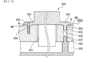
(変形例)
図27には、装飾部材の遊技盤面200aへの取付構造の変形例が示されている。例えば装飾部材25L等と同様に遊技領域7に配設される他の装飾部材650においては、フランジ部651を遊技盤面200aに当接しないように配置し、取付ネジ652の周囲から遊技盤面200aに向けて凸部654を突設し、該凸部654の先端のみを当接させるようにしてもよい。このようにすることでも遊技盤面200a側の縁辺部Hに切欠凹溝KMが形成され、この切欠凹溝KMにより縁辺部Hと遊技盤面200aとの間に隙間が形成され、枠状部640に遊技球が接触することにより振動が生じても、縁辺部Hと遊技盤面200aとが擦れることがないので、遊技盤面200aが削れることにより生じた粉が遊技盤面200aに付着して遊技盤面200aが汚れることがない。
(Modification)
FIG. 27 shows a modification of the structure for attaching the decorative member to the
尚、フランジ部651における遊技盤面200a側の縁辺部Hとは、フランジ部651における遊技盤面200aと対向する対向面(後面)の外周の辺部であり、反対側の面(前面)の周縁辺は含まない。
The edge portion H on the
また、凸部655の先端から、合成樹脂板200に形成された位置決め穴656に嵌合可能な位置決めピン653を突設し、フランジ部651における位置決めピン653の周囲を遊技盤面200aに当接させるようにしてもよい。また、位置決めピン653が前面側から嵌合される位置決め穴656の背面側からは、スペーサ部材250側の位置決めピン657が嵌合されるようにしてもよく、このようにすることで、位置決め穴656を装飾部材650とスペーサ部材250との間で共用することができるため、それぞれの位置決め穴を別個に形成する場合に比べて合成樹脂板200の強度低下を防止できるばかりか、穴あけ加工の手間を省くことができる。
Further, a
尚、ここでは遊技盤面200aが形成される合成樹脂板200の裏面側に取り付けられ、遊技に関連する遊技用部品が組み付けられるユニット部材として、スペーサ部材250を一例に挙げて説明したが、遊技に関連する遊技用部品の一例である演出表示装置9や演出制御基板80等を含む変動表示ユニット49や、合成樹脂板200の裏面側に取り付けられる種々の構造物等であってもよい。
Here, the
(可変入賞球装置)
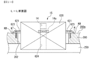
遊技媒体通路部材の一例である可変入賞球装置15(図1参照)は、取付穴202に取り付けられる。図24に示すように、可変入賞球装置15は、取付穴202の周縁部に装着される枠状の本体部620と、本体部620の周面から外方に向けて突設され、遊技盤面200aにおける取付穴202の周縁部に配置されるフランジ部621と、から構成され、フランジ部621を取付ネジ623にて遊技盤面200aに取り付けできるようになっている。
(Variable winning ball device)
A variable winning ball device 15 (see FIG. 1), which is an example of a game medium passage member, is attached to the
本体部620は、後部が取付穴202に嵌合されるとともに、前部は遊技盤面200a上に配置され、遊技領域7内を流下する遊技球と接触可能に配設されている。前部の上面には第2始動入賞口14が形成されているとともに、内部には該第2始動入賞口14に進入した遊技球を合成樹脂板200の裏面側に排出するための通路部としての入賞球誘導通路624が形成されている。また、入賞球誘導通路624には該通路内を通過する遊技球を検出するための第2始動口スイッチ14aが配設されている。
The
このように構成される本体部620の周囲に形成されたフランジ部621における遊技盤面200a側の縁辺部Hに切欠凹溝KMが形成されていることで、この切欠凹溝KMにより縁辺部Hと遊技盤面200aとの間に隙間が形成され、本体部620の前面に遊技球が接触することにより振動が生じても、縁辺部Hと遊技盤面200aとが擦れることがないので、遊技盤面200aが削れることにより生じた粉が遊技盤面200aに付着して遊技盤面200aが汚れることがない。
The notch groove KM is formed in the edge portion H on the
尚、本体部620のフランジ部621における遊技盤面200a側の縁辺部Hとは、フランジ部621における遊技盤面200aと対向する対向面(後面)の外周の辺部であり、反対側の面(前面)の周縁辺は含まない。
The edge H on the
尚、この切欠凹溝KMは本体部620の周縁全体に形成されているため、本体部620において遊技領域7を流下する遊技球が直接落下または当接しうる箇所の縁辺部Hと遊技盤面200aとが擦れることがない。
Since the notch groove KM is formed on the entire periphery of the
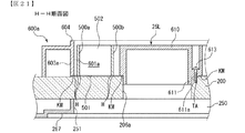
(ゲート)
図26に示すように、遊技媒体通路部材の一例であるゲート32は、遊技盤面200aの取付穴205に取り付けられるゲート部材32bと、該ゲート部材32bに装着されるゲートスイッチ32aと、から構成される。ゲートスイッチ32aの本体は、平面視長方形状をなす板状部材にて構成され、前側に上方から流下してくる遊技球を下方に通過可能な大きさを有する開口32cが上下に貫通して形成され、該開口32c内を通過する遊技球を検出可能に構成されている。
(Gate)
As shown in FIG. 26, the
ゲート部材32bは、遊技盤面200a側に配置される四角枠状に形成された枠状部640と、この枠状部640の基部から外方に向けて突設され、遊技盤面200aにおける取付穴205の周縁部に配置されるフランジ部643と、から構成され、フランジ部643を取付ネジ642にて遊技盤面200aに取り付けできるようになっている。
The
枠状部640は、ゲートスイッチ32aの開口32cを上下に開放するための開口641を有するとともに、左右辺部の内面側には、ゲートスイッチ32aの本体の左右両側をガイドする前後方向を向くガイド溝645,645が形成されている。フランジ部643の背面には、ゲートスイッチ32aの本体を挿通可能な横長四角形状(図示略)をなす挿通穴649が形成されているとともに、該挿通穴649の左右側には、取付穴205内に前面側から嵌合される左右一対の嵌合部646,646が背面側に向けて突設されている。嵌合部646,646は正面視コ字形に形成され、互いに内向きに開口してゲートスイッチ32aの本体を左右側から挟持可能に配置されている。
The frame-shaped
また、前面側から見て右側(図26中左側)の嵌合部646からは、枠状部640内に差し込まれたゲートスイッチ32aの本体部の後端に係止して逸脱を規制する弾性係止爪648が背面側に向けて突設されている。弾性係止爪648は、ゲート部材32bを遊技盤面200aに取り付けた状態において、取付穴201の開口から合成樹脂板200の背面側に突出して配置されるように設けられ、取付穴201の開口から突出した部位が弾性変形することによりゲートスイッチ32aの本体部に係脱するようになっている。
In addition, from the
また、フランジ部643における遊技盤面200a側の縁辺部Hに切欠凹溝KMが形成されていることで、この切欠凹溝KMにより縁辺部Hと遊技盤面200aとの間に隙間が形成され、枠状部640に遊技球が接触することにより振動が生じても、縁辺部Hと遊技盤面200aとが擦れることがないので、遊技盤面200aが削れることにより生じた粉が遊技盤面200aに付着して遊技盤面200aが汚れることがない。
Further, since the notch groove KM is formed in the edge portion H on the
尚、フランジ部643における遊技盤面200a側の縁辺部Hとは、フランジ部643における遊技盤面200aと対向する対向面(後面)の外周の辺部であり、反対側の面(前面)の周縁辺は含まない。
The edge portion H on the
尚、この切欠凹溝KMはフランジ部643の周縁全体に形成されているため、フランジ部643において遊技領域7を流下する遊技球が直接落下または当接しうる箇所の縁辺部Hと遊技盤面200aとが擦れることがない。
Since this notch groove KM is formed on the entire periphery of the
このように構成されたゲート32は、遊技盤面200a側からゲート部材32bの嵌合部646,646を取付穴205に嵌合するとともに、フランジ部643の背面に突設された位置決めピン647を遊技盤面200aに形成された位置決め穴に嵌合して位置決めした状態で、取付ネジ642を遊技盤面200aに止着することで取り付けられる。
The
そして、ゲートスイッチ32aの本体を、合成樹脂板200の背面側から取付穴201の開口に配置されたゲート部材32bの挿通穴649に前面側に向けて差し込むことで、本体の後部が弾性係止爪648に係止されてゲート部材32bに装着される。また、弾性係止爪648を変形させて係止状態を解除するだけでゲートスイッチ32aを簡単に取り外すことができる。
And the rear part of the main body is elastically locked by inserting the main body of the
このように遊技球が通過可能な通路部を構成する開口32cが遊技盤面200a側に配置され、該開口32cを通過する遊技球を検出するゲートスイッチ32aを、遊技盤面200a側に取り付けられるゲート部材32bに対して合成樹脂板200の背面側から着脱できるように構成されていることで、ゲートスイッチ32aの本体の後部から延出される配線(図26(b)参照)や該配線を基板等に接続するためのコネクタ(図示略)等を取付穴205内に挿通することなく取り付けることができるため、例えばゲートスイッチ32aが故障するなどして交換やメンテナンスが必要になった場合、ゲート部材32bを取り外さずにゲートスイッチ32aのみを交換することができる。また、ゲートスイッチ32aの本体の側端面は、ゲート部材32bの枠状部640内に差し込まれることにより被覆されるため、遊技球との接触による損傷や破損が防止される。
Thus, the
以上説明してきたように、本実施例では、外レール飾り600a〜600c、装飾部材25L,25R、600、センター飾り11、ゲート部材32b、可変入賞球装置15等の遊技領域7に配設される遊技部材の本体部における遊技盤面200a側の縁辺部Hに切欠凹溝KMを形成することで縁辺部Hと遊技盤面200aとの間に隙間を形成していたが、球戻り防止装置700のように、遊技部材の本体部における遊技盤面200aと対向する対向面における所定箇所に凸部(当接部)を突設し、該凸部のみを遊技盤面200aに設置させることで、遊技部材の本体部における遊技盤面200a側の縁辺部Hと遊技盤面200aとの間に隙間を形成するようにしてもよい。
As described above, in the present embodiment, the
また、これら遊技部材の縁辺部Hに形成される切欠凹溝KMは、各遊技部材において遊技球と当接する可能性がある遊技球当接面、つまり遊技領域7に臨む縁辺部Hに沿って形成されていれば、必ずしも本体部の周縁辺部全体に形成されていなくてもよい。
Further, the notch groove KM formed in the edge portion H of these game members is along the game ball contact surface that may contact the game ball in each game member, that is, along the edge portion H facing the
また、各遊技部材に形成された切欠凹溝KMにより遊技盤面200aとの間に形成された隙間に、振動を吸収可能なゴム材等の緩衝材等を嵌合してもよく、このようにすることで、切欠凹溝KMよりも内側において遊技盤面200aと擦れることにより削れた粉等が周囲に飛散することが防止される。
Further, a cushioning material such as a rubber material that can absorb vibrations may be fitted into a gap formed between the
以上、本発明の実施例を図面により説明してきたが、具体的な構成はこれら実施例に限られるものではなく、本発明の要旨を逸脱しない範囲における変更や追加があっても本発明に含まれる。 Although the embodiments of the present invention have been described with reference to the drawings, the specific configuration is not limited to these embodiments, and modifications and additions within the scope of the present invention are included in the present invention. It is.
1 パチンコ遊技機
6 遊技盤
11 センター枠飾り
15 可変入賞球装置
25L,25R 装飾部材
32 ゲート
49 変動表示ユニット
110 遊技枠
120 機構板
200 合成樹脂板
200a 遊技盤面
250 スペーサ部材
265a〜265d カバー体用位置決め穴
260a〜260h 取付用ボス
264c、264f 嵌合凹部
266a〜266d 案内凹溝
267 係合段部
300 遊技用部品ユニット
301 装飾体
302 カバー体
312a〜312d 位置決め用ボス
400 遊技盤ユニット
600a〜600c 外レール飾り
700 球戻り防止装置
KM 切欠凹溝
H 縁辺部
DESCRIPTION OF SYMBOLS 1
Claims (1)
遊技盤面上における前記遊技領域に配設され、該遊技領域を装飾する装飾部材と、
前記装飾部材の前記遊技盤面に沿う方向への移動を規制するための規制部と、
を備え、
前記装飾部材を前記遊技盤面に取り付けた取付状態において、該装飾部材における前記遊技盤面側の縁辺部と前記遊技盤面との間に、該縁辺部と前記遊技盤面との当接を防止するための隙間が形成され、
前記装飾部材は、前記遊技盤面側の前記縁辺部よりも内側から前記遊技盤面側に突設され、前記取付状態において前記遊技盤面に当接する当接部を備える
ことを特徴とする遊技機。 A gaming machine comprising a gaming board made of a synthetic resin plate having translucency and having a gaming area in which gaming media can flow down,
A decorative member disposed in the game area on the game board surface and decorating the game area;
A restricting portion for restricting movement of the decorative member in a direction along the game board surface;
With
In the attached state in which the decorative member is attached to the game board surface, the contact between the edge portion of the decorative member on the game board surface side and the game board surface between the edge portion and the game board surface is prevented. A gap is formed,
The gaming machine is characterized in that the decoration member includes a contact portion that protrudes from the inner side of the edge portion on the game board surface side toward the game board surface side and contacts the game board surface in the attached state.
Priority Applications (1)
| Application Number | Priority Date | Filing Date | Title |
|---|---|---|---|
| JP2015083024A JP5906339B2 (en) | 2015-04-15 | 2015-04-15 | Game machine |
Applications Claiming Priority (1)
| Application Number | Priority Date | Filing Date | Title |
|---|---|---|---|
| JP2015083024A JP5906339B2 (en) | 2015-04-15 | 2015-04-15 | Game machine |
Related Parent Applications (1)
| Application Number | Title | Priority Date | Filing Date |
|---|---|---|---|
| JP2009236676A Division JP5735205B2 (en) | 2009-10-13 | 2009-10-13 | Game machine |
Publications (2)
| Publication Number | Publication Date |
|---|---|
| JP2015128707A JP2015128707A (en) | 2015-07-16 |
| JP5906339B2 true JP5906339B2 (en) | 2016-04-20 |
Family
ID=53759906
Family Applications (1)
| Application Number | Title | Priority Date | Filing Date |
|---|---|---|---|
| JP2015083024A Active JP5906339B2 (en) | 2015-04-15 | 2015-04-15 | Game machine |
Country Status (1)
| Country | Link |
|---|---|
| JP (1) | JP5906339B2 (en) |
Cited By (1)
| Publication number | Priority date | Publication date | Assignee | Title |
|---|---|---|---|---|
| JP2020081105A (en) * | 2018-11-19 | 2020-06-04 | 株式会社ニューギン | Game machine |
Family Cites Families (3)
| Publication number | Priority date | Publication date | Assignee | Title |
|---|---|---|---|---|
| JP4274292B2 (en) * | 1998-02-24 | 2009-06-03 | 株式会社大一商会 | Ball return prevention device for pachinko machines |
| JP2008237564A (en) * | 2007-03-27 | 2008-10-09 | Toyomaru Industry Co Ltd | Game machine |
| JP4664945B2 (en) * | 2007-06-20 | 2011-04-06 | 株式会社エース電研 | Game machine |
-
2015
- 2015-04-15 JP JP2015083024A patent/JP5906339B2/en active Active
Cited By (2)
| Publication number | Priority date | Publication date | Assignee | Title |
|---|---|---|---|---|
| JP2020081105A (en) * | 2018-11-19 | 2020-06-04 | 株式会社ニューギン | Game machine |
| JP7006935B2 (en) | 2018-11-19 | 2022-01-24 | 株式会社ニューギン | Pachinko machine |
Also Published As
| Publication number | Publication date |
|---|---|
| JP2015128707A (en) | 2015-07-16 |
Similar Documents
| Publication | Publication Date | Title |
|---|---|---|
| JP5735205B2 (en) | Game machine | |
| JP5409271B2 (en) | Game machine | |
| JP5513077B2 (en) | Game machine | |
| JP5524709B2 (en) | Game machine | |
| JP2006087549A (en) | Game machine | |
| JP6170679B2 (en) | Game machine | |
| JP2012065963A (en) | Game machine | |
| JP5524708B2 (en) | Game machine | |
| JP5735203B2 (en) | Game machine | |
| JP5906338B2 (en) | Game machine | |
| JP5409270B2 (en) | Game machine | |
| JP5906339B2 (en) | Game machine | |
| JP5735206B2 (en) | Game machine | |
| JP5906340B2 (en) | Game machine | |
| JP5906337B2 (en) | Game machine | |
| JP5735204B2 (en) | Game machine | |
| JP5777073B2 (en) | Game machine | |
| JP5807932B2 (en) | Game machine | |
| JP5777072B2 (en) | Game machine | |
| JP5807931B2 (en) | Game machine | |
| JP5513076B2 (en) | Game machine | |
| JP5784935B2 (en) | Game machine | |
| JP5946858B2 (en) | Game machine | |
| JP5946857B2 (en) | Game machine | |
| JP5807923B2 (en) | Game machine |
Legal Events
| Date | Code | Title | Description |
|---|---|---|---|
| A621 | Written request for application examination |
Free format text: JAPANESE INTERMEDIATE CODE: A621 Effective date: 20150415 |
|
| TRDD | Decision of grant or rejection written | ||
| A01 | Written decision to grant a patent or to grant a registration (utility model) |
Free format text: JAPANESE INTERMEDIATE CODE: A01 Effective date: 20160315 |
|
| A977 | Report on retrieval |
Free format text: JAPANESE INTERMEDIATE CODE: A971007 Effective date: 20160318 |
|
| A61 | First payment of annual fees (during grant procedure) |
Free format text: JAPANESE INTERMEDIATE CODE: A61 Effective date: 20160318 |
|
| R150 | Certificate of patent or registration of utility model |
Ref document number: 5906339 Country of ref document: JP Free format text: JAPANESE INTERMEDIATE CODE: R150 |
|
| R250 | Receipt of annual fees |
Free format text: JAPANESE INTERMEDIATE CODE: R250 |
|
| R250 | Receipt of annual fees |
Free format text: JAPANESE INTERMEDIATE CODE: R250 |
|
| R250 | Receipt of annual fees |
Free format text: JAPANESE INTERMEDIATE CODE: R250 |
|
| R250 | Receipt of annual fees |
Free format text: JAPANESE INTERMEDIATE CODE: R250 |
|
| R250 | Receipt of annual fees |
Free format text: JAPANESE INTERMEDIATE CODE: R250 |
|
| R250 | Receipt of annual fees |
Free format text: JAPANESE INTERMEDIATE CODE: R250 |