JP5906239B2 - Retainer for transcatheter heart valve delivery system - Google Patents
Retainer for transcatheter heart valve delivery system Download PDFInfo
- Publication number
- JP5906239B2 JP5906239B2 JP2013519648A JP2013519648A JP5906239B2 JP 5906239 B2 JP5906239 B2 JP 5906239B2 JP 2013519648 A JP2013519648 A JP 2013519648A JP 2013519648 A JP2013519648 A JP 2013519648A JP 5906239 B2 JP5906239 B2 JP 5906239B2
- Authority
- JP
- Japan
- Prior art keywords
- retainer
- receiving portion
- piece
- delivery device
- stent
- Prior art date
- Legal status (The legal status is an assumption and is not a legal conclusion. Google has not performed a legal analysis and makes no representation as to the accuracy of the status listed.)
- Expired - Fee Related
Links
Images


Classifications
-
- A—HUMAN NECESSITIES
- A61—MEDICAL OR VETERINARY SCIENCE; HYGIENE
- A61F—FILTERS IMPLANTABLE INTO BLOOD VESSELS; PROSTHESES; DEVICES PROVIDING PATENCY TO, OR PREVENTING COLLAPSING OF, TUBULAR STRUCTURES OF THE BODY, e.g. STENTS; ORTHOPAEDIC, NURSING OR CONTRACEPTIVE DEVICES; FOMENTATION; TREATMENT OR PROTECTION OF EYES OR EARS; BANDAGES, DRESSINGS OR ABSORBENT PADS; FIRST-AID KITS
- A61F2/00—Filters implantable into blood vessels; Prostheses, i.e. artificial substitutes or replacements for parts of the body; Appliances for connecting them with the body; Devices providing patency to, or preventing collapsing of, tubular structures of the body, e.g. stents
- A61F2/02—Prostheses implantable into the body
- A61F2/24—Heart valves ; Vascular valves, e.g. venous valves; Heart implants, e.g. passive devices for improving the function of the native valve or the heart muscle; Transmyocardial revascularisation [TMR] devices; Valves implantable in the body
- A61F2/2427—Devices for manipulating or deploying heart valves during implantation
- A61F2/2436—Deployment by retracting a sheath
-
- A—HUMAN NECESSITIES
- A61—MEDICAL OR VETERINARY SCIENCE; HYGIENE
- A61F—FILTERS IMPLANTABLE INTO BLOOD VESSELS; PROSTHESES; DEVICES PROVIDING PATENCY TO, OR PREVENTING COLLAPSING OF, TUBULAR STRUCTURES OF THE BODY, e.g. STENTS; ORTHOPAEDIC, NURSING OR CONTRACEPTIVE DEVICES; FOMENTATION; TREATMENT OR PROTECTION OF EYES OR EARS; BANDAGES, DRESSINGS OR ABSORBENT PADS; FIRST-AID KITS
- A61F2/00—Filters implantable into blood vessels; Prostheses, i.e. artificial substitutes or replacements for parts of the body; Appliances for connecting them with the body; Devices providing patency to, or preventing collapsing of, tubular structures of the body, e.g. stents
- A61F2/95—Instruments specially adapted for placement or removal of stents or stent-grafts
- A61F2/9522—Means for mounting a stent or stent-graft onto or into a placement instrument
-
- A—HUMAN NECESSITIES
- A61—MEDICAL OR VETERINARY SCIENCE; HYGIENE
- A61F—FILTERS IMPLANTABLE INTO BLOOD VESSELS; PROSTHESES; DEVICES PROVIDING PATENCY TO, OR PREVENTING COLLAPSING OF, TUBULAR STRUCTURES OF THE BODY, e.g. STENTS; ORTHOPAEDIC, NURSING OR CONTRACEPTIVE DEVICES; FOMENTATION; TREATMENT OR PROTECTION OF EYES OR EARS; BANDAGES, DRESSINGS OR ABSORBENT PADS; FIRST-AID KITS
- A61F2/00—Filters implantable into blood vessels; Prostheses, i.e. artificial substitutes or replacements for parts of the body; Appliances for connecting them with the body; Devices providing patency to, or preventing collapsing of, tubular structures of the body, e.g. stents
- A61F2/95—Instruments specially adapted for placement or removal of stents or stent-grafts
- A61F2/962—Instruments specially adapted for placement or removal of stents or stent-grafts having an outer sleeve
- A61F2/966—Instruments specially adapted for placement or removal of stents or stent-grafts having an outer sleeve with relative longitudinal movement between outer sleeve and prosthesis, e.g. using a push rod
- A61F2002/9665—Instruments specially adapted for placement or removal of stents or stent-grafts having an outer sleeve with relative longitudinal movement between outer sleeve and prosthesis, e.g. using a push rod with additional retaining means
Description
[関連出願の相互参照]
本願は、2010年7月15日に出願された米国仮特許出願第61/364,453号の出願日の利得を主張するものであり、その開示内容は、参照することによって、ここに含まれるものとする。
[Cross-reference of related applications]
This application claims the benefit of the filing date of US Provisional Patent Application No. 61 / 364,453, filed July 15, 2010, the disclosure of which is hereby incorporated by reference. Shall.
[発明の分野]
本発明は、人工心臓弁置換に関し、さらに詳細には、折畳み可能な人工心臓弁の経カテーテル送達のための装置、システム、および方法に関する。
[Field of the Invention]
The present invention relates to prosthetic heart valve replacement, and more particularly to an apparatus, system, and method for transcatheter delivery of a foldable prosthetic heart valve.
比較的小さい周方向寸法に折畳み可能な人工心臓弁は、折畳み可能になっていない弁よりも低侵襲的に患者内に送達されることが可能である。例えば、折畳み可能な弁は、カテーテル、トロカール、腹腔鏡器具、などのような管状送達装置を介して、患者内に送達されることになる。この折畳み性によって、完全な開胸手術、すなわち、心臓切開手術のようなより侵襲性の高い手術を行う必要性を回避することができる。 A prosthetic heart valve that is foldable to a relatively small circumferential dimension can be delivered into a patient less invasively than a valve that is not foldable. For example, the foldable valve will be delivered into the patient via a tubular delivery device such as a catheter, trocar, laparoscopic instrument, and the like. This foldability avoids the need to perform a complete thoracotomy, i.e., a more invasive procedure such as an open heart operation.
折畳み可能な人工心臓弁は、典型的には、ステントに取り付けられた弁構造体の形態を取っている。折畳み可能な弁が取り付けられるステントには、2つの形式、すなわち、自己拡張型ステントおよびバルーン拡張型ステントがある。折畳み可能な弁を送達装置内に設置し、最終的に患者内に配置するために、弁は、最初に、その周方向寸法を縮小するために折畳みまたは圧着されねばならない。 A foldable prosthetic heart valve typically takes the form of a valve structure attached to a stent. There are two types of stents to which a foldable valve is attached: a self-expanding stent and a balloon expandable stent. In order to install a foldable valve in a delivery device and ultimately place it in a patient, the valve must first be folded or crimped to reduce its circumferential dimension.
折畳み可能な弁が患者内の所望の移植部位(例えば、人工弁によって置換されることになる患者の心臓弁輪またはその近傍)に達したとき、心臓弁は、送達装置から離脱され、十分な作用寸法に再拡張されることになる。 When the foldable valve reaches the desired implantation site in the patient (eg, at or near the patient's heart valve annulus that is to be replaced by the prosthetic valve), the heart valve is disengaged from the delivery device and sufficient It will be re-expanded to the working dimensions.
折畳み可能な人工心臓弁送達プロセスに対してこれまでになされてきた種々の改良にも関わらず、従来の装置、システム、および方法は、いくつかの欠点を抱えている。例えば、自己拡張型折畳み可能な弁は、カテーテルのリテーナ部分内に挿入されたステント保持部材によって、カテーテル内に保持されることがある。この自己拡張型弁を所望の領域(例えば、大動脈弁輪)内に展開している間に、弁の鞘出し中に生じた高摩擦力が、2つまたは3つの保持部材に直接加えられる高軸方向力をもたらし、これによって、これらの保持部材を支持するステント支柱を損傷または変形させることがある。 Despite the various improvements that have been made to the foldable prosthetic heart valve delivery process, conventional devices, systems, and methods suffer from several drawbacks. For example, a self-expanding foldable valve may be retained in the catheter by a stent retaining member inserted in the retainer portion of the catheter. While deploying this self-expanding valve in a desired area (eg, an aortic annulus), high frictional forces created during valve sheathing are applied directly to the two or three retaining members. An axial force may be provided, thereby damaging or deforming the stent struts supporting these retaining members.
さらに、送達プロセスによって、ステントがカテーテルのリテーナ部分に対して捩じられ、その結果、ステント保持部材が展開中にリテーナに引っ掛かることによって、弁を離脱させることが困難になることがある。 In addition, the delivery process can cause the stent to twist relative to the retainer portion of the catheter, which can make it difficult to disengage the valve by catching the stent retaining member on the retainer during deployment.
従って、折畳み可能な人工心臓弁の経カテーテル送達のための装置、システム、および方法に対するさらなる改良が必要とされている。とりわけ、本発明の利点は、これらの欠点の1つまたは複数に対処することである。 Accordingly, there is a need for further improvements to devices, systems, and methods for transcatheter delivery of foldable prosthetic heart valves. Among other things, an advantage of the present invention is to address one or more of these drawbacks.
移植可能な医学装置用の送達装置、移植可能な医学装置の送達のためのシステム、および人工弁の送達の方法が、開示されている。 A delivery device for an implantable medical device, a system for delivery of an implantable medical device, and a method for delivery of a prosthetic valve are disclosed.
少なくとも1つの保持部材を一端に有する移植可能な医学装置用の送達装置は、長手方向に延在しているシャフトと、シャフトの長手方向部分を囲んでいる細長シースであって、シャフトに対して長手方向に摺動可能になっている細長シースと、シースの内側に画定され、組立状態にある医学装置を受容するように構成された区画と、区画の一端に配置されたリテーナであって、内側片と、内側片の周りに回転可能となるように、かつ内側片に対して長手方向における運動が制約されるように、内側片上に取り付けられた外側片とを備えているリテーナと、組立状態にある医学装置の保持部材を受け入れるように構成された、リテーナ内の少なくとも1つの受入れ部とを備えている。 A delivery device for an implantable medical device having at least one retaining member at one end includes a longitudinally extending shaft and an elongated sheath surrounding the longitudinal portion of the shaft, the An elongate sheath that is slidable longitudinally; a compartment defined inside the sheath and configured to receive an assembled medical device; and a retainer disposed at one end of the compartment, A retainer comprising an inner piece and an outer piece mounted on the inner piece so as to be rotatable about the inner piece and restricted in longitudinal movement relative to the inner piece; At least one receiving portion in the retainer configured to receive the retaining member of the medical device in a condition.
外側片および内側片の一方は、周方向に延在する溝を備えていてもよく、外側片および内側片の他方は、溝内に組み込まれて外側片が内側片の周りを回転することを可能にする環状リングを備えていてもよい。リテーナは、内側片上に取り付けられて外側片に固定して接続された支持片をさらに備えていてもよく、これによって、外側片および支持片は、内側片の周りを一緒に回転可能になっている。医学装置は、複数の支柱を有する自己拡張型ステントを備えていてもよく、外側片は、区画と向き合った保持縁、および保持縁における開端から閉端に向かって長手方向に延在する少なくとも1つの凹部を有していてもよく、凹部は、組立状態にあるステントの端における複数の支柱の1つを受け入れるように、構成されていてもよい。 One of the outer piece and the inner piece may be provided with a circumferentially extending groove, the other of the outer piece and the inner piece being incorporated in the groove so that the outer piece rotates around the inner piece. An annular ring may be provided to allow for this. The retainer may further comprise a support piece mounted on the inner piece and fixedly connected to the outer piece, so that the outer piece and the support piece can rotate together around the inner piece. Yes. The medical device may comprise a self-expanding stent having a plurality of struts, wherein the outer piece has a retaining edge facing the compartment and at least one extending longitudinally from the open end to the closed end at the retaining edge. There may be one recess and the recess may be configured to receive one of the plurality of struts at the end of the stent in the assembled state.
受入れ部は、組立状態において複数の支柱の1つが凹部の閉端に接触すると共に、保持部材が受入れ部の閉端から離間するような、長手方向長さを有していてもよい。外側片は、区画と向き合った保持縁を有していてもよく、受入れ部は、保持部材を受け入れるように寸法決めされた第1の領域を有していてもよく、受入れ部は、第1の領域と保持縁との間に狭小ネックを画定する少なくとも1つの突起を備えていてもよい。また、送達装置は、少なくとも1つの受入れ部から半径方向外方に延在しているピンであって、保持部材の開口に係合するように構成されているピンと、該ピンに連結されたアクチュエータであって、ピンを長手方向に移動させるように構成されており、これによって、受入れ部に対する保持部材の長手方向位置を調整するようになっているアクチュエータとを備えていてもよい。医学装置は、自己拡張型折畳み可能な人工弁であってもよい。 The receiving portion may have a length in the longitudinal direction such that one of the plurality of support columns contacts the closed end of the recess in the assembled state, and the holding member is separated from the closed end of the receiving portion. The outer piece may have a retaining edge facing the compartment, the receiving portion may have a first region dimensioned to receive the retaining member, and the receiving portion is a first portion. And at least one protrusion defining a narrow neck between the region and the retaining edge. The delivery device also includes a pin extending radially outward from the at least one receiving portion, the pin configured to engage the opening of the holding member, and an actuator coupled to the pin And it is comprised so that a pin may be moved to a longitudinal direction, and you may provide the actuator by which the longitudinal direction position of the holding member with respect to a receiving part is adjusted by this. The medical device may be a self-expanding foldable prosthetic valve.
移植可能な医学装置を送達するためのシステムは、長手方向に延在しているシャフトと、シャフトの長手方向部分を囲んでいる細長シースであって、シャフトに対して長手方向に摺動可能になっている細長シースと、シースの内側に画定された区画と、区画の一端に配置されたリテーナであって、内側片と、内側片の周りに回転可能となるように、かつ内側片に対して長手方向における運動が制約されるように、内側片上に取り付けられた外側片とを備えているリテーナと、リテーナ内の少なくとも1つの受入れ部とを備えた、送達装置を備えている。移植可能な医学装置を送達するためのシステムは、区画内に組み込まれた移植可能な医学装置であって、その一端に少なくとも1つの保持部材を有しており、保持部材は受入れ部内に配置されている、医学装置も備えている。 A system for delivering an implantable medical device includes a longitudinally extending shaft and an elongate sheath surrounding a longitudinal portion of the shaft that is slidable longitudinally relative to the shaft. An elongated sheath, a compartment defined inside the sheath, and a retainer disposed at one end of the compartment, the inner piece being rotatable about the inner piece and relative to the inner piece A delivery device comprising a retainer having an outer piece mounted on the inner piece and at least one receiving portion in the retainer so that movement in the longitudinal direction is constrained. A system for delivering an implantable medical device is an implantable medical device incorporated within a compartment having at least one retaining member at one end thereof, the retaining member being disposed within the receiving portion. It also has a medical device.
外側片および内側片の一方は、周方向に延在する溝を備えていてもよく、外側片および内側片の他方は、溝に組み込まれて外側片が内側片の周りを回転することを可能にする環状リングを備えていてもよい。リテーナは、内側片上に取り付けられ、外側片に固定して接続された支持片をさらに備えていてもよく、これによって、外側片および支持片は、内側片の周りを一緒に回転可能になっている。医学装置は、複数の支柱を有する自己拡張型ステントを備えていてもよく、外側片は、区画と向き合った保持縁、および保持縁における開端から閉端に向かって長手方向に延在する少なくとも1つの凹部を有していてもよく、ステントの端における複数の支柱の1つは、凹部内に組み込まれていてもよい。 One of the outer piece and the inner piece may have a circumferentially extending groove, and the other of the outer piece and the inner piece is incorporated into the groove to allow the outer piece to rotate around the inner piece. An annular ring may be provided. The retainer may further comprise a support piece mounted on the inner piece and fixedly connected to the outer piece, so that the outer piece and the support piece can rotate together around the inner piece. Yes. The medical device may comprise a self-expanding stent having a plurality of struts, wherein the outer piece has a retaining edge facing the compartment and at least one extending longitudinally from the open end to the closed end at the retaining edge. There may be one recess and one of the plurality of struts at the end of the stent may be incorporated within the recess.
受入れ部は、複数の支柱の1つが凹部の閉端に接触すると共に保持部材が受入れ部の閉端から離間するような、長手方向長さを有していてもよい。外側片は、区画と向き合った保持縁を有していてもよく、受入れ部は、保持部材を受け入れるように寸法決めされた第1の領域を有していてもよく、受入れ部は、第1の領域と保持縁との間に狭小ネックを画定する少なくとも1つの突起を備えていてもよい。また、移植可能な医学装置を送達するためのシステムは、少なくとも1つの受入れ部から半径方向外方に延在して保持部材の開口に係合されたピンと、該ピンに連結されたアクチュエータであって、ピンを長手方向に移動させるように構成されており、これによって、受入れ部に対する保持部材の長手方向位置を調整するようになっているアクチュエータとを備えていてもよい。 The receiving part may have a longitudinal length such that one of the plurality of support columns contacts the closed end of the recess and the holding member is separated from the closed end of the receiving part. The outer piece may have a retaining edge facing the compartment, the receiving portion may have a first region dimensioned to receive the retaining member, and the receiving portion is a first portion. And at least one protrusion defining a narrow neck between the region and the retaining edge. Also, a system for delivering an implantable medical device includes a pin that extends radially outward from at least one receiving portion and engages an opening in a retaining member, and an actuator coupled to the pin. The actuator may be configured to move the pin in the longitudinal direction and thereby adjust the longitudinal position of the holding member with respect to the receiving portion.
少なくとも1つの保持部材を一端に有する移植可能な医学装置用の送達装置は、長手方向に延在しているシャフトと、シャフトの長手方向部分を囲んでいる細長シースであって、シャフトに対して長手方向に摺動可能になっている細長シースと、シースの内側に画定され、組立状態にある医学装置を受容するように構成された区画と、区画の一端に配置されたリテーナであって、区画と向き合った保持縁を有しているリテーナと、組立状態にある医学装置の保持部材を受け入れるように適合された、リテーナ内の少なくとも1つの受入れ部であって、組立状態において受入れ部の長さが保持部材の長手方向長さよりも大きくなるような長手方向長さを有している受入れ部とを備えている。 A delivery device for an implantable medical device having at least one retaining member at one end includes a longitudinally extending shaft and an elongated sheath surrounding the longitudinal portion of the shaft, the An elongate sheath that is slidable longitudinally; a compartment defined inside the sheath and configured to receive an assembled medical device; and a retainer disposed at one end of the compartment, A retainer having a retaining edge facing the compartment and at least one receiving portion in the retainer adapted to receive a retaining member of the assembled medical device, the length of the receiving portion in the assembled state And a receiving portion having a length in the longitudinal direction such that the length is larger than the length in the longitudinal direction of the holding member.
医学装置は、複数の支柱を有する自己拡張型ステントを備えていてもよく、リテーナは、保持縁における開端から閉端に向かって長手方向に延在する少なくとも1つの凹部を有していてもよく、凹部は、組立状態にあるステントの端における複数の支柱の1つを受け入れるように、構成されていてもよい。受入れ部は、保持部材を受け入れるように寸法決めされた第1の領域を有していてもよく、受入れ部は、第1の領域と保持縁との間に狭小ネックを画定する少なくとも1つの突起を備えていてもよい。医学装置は、自己拡張型折畳み可能な人工弁であってもよい。 The medical device may comprise a self-expanding stent having a plurality of struts, and the retainer may have at least one recess extending longitudinally from the open end to the closed end at the retaining edge. The recess may be configured to receive one of a plurality of struts at the end of the stent in the assembled state. The receiving portion may have a first region dimensioned to receive a retaining member, the receiving portion defining at least one protrusion that defines a narrow neck between the first region and the retaining edge. May be provided. The medical device may be a self-expanding foldable prosthetic valve.
また、送達装置は、少なくとも1つの受入れ部から半径方向外方に延在しているピンであって、保持部材の開口に係合するように構成されているピンと、該ピンに連結されたアクチュエータであって、ピンを長手方向に移動させるように構成されており、これによって、受入れ部に対する保持部材の長手方向位置を調整するようになっているアクチュエータとを備えていてもよい。組立状態において、複数の支柱の1つは、凹部の閉端に接触していてもよく、保持部材は、受入れ部の閉端から離間していてもよい。受入れ部は、保持部材を受け入れるように寸法決めされた第1の領域を有していてもよく、受入れ部は、第1の領域と保持縁との間に狭小ネックを画定する少なくとも1つの突起を備えていてもよい。 The delivery device also includes a pin extending radially outward from the at least one receiving portion, the pin configured to engage the opening of the holding member, and an actuator coupled to the pin And it is comprised so that a pin may be moved to a longitudinal direction, and you may provide the actuator by which the longitudinal direction position of the holding member with respect to a receiving part is adjusted by this. In the assembled state, one of the plurality of support columns may be in contact with the closed end of the recess, and the holding member may be separated from the closed end of the receiving portion. The receiving portion may have a first region dimensioned to receive a retaining member, the receiving portion defining at least one protrusion that defines a narrow neck between the first region and the retaining edge. May be provided.
人工弁を送達する方法は、少なくとも1つの保持部材を一端に有する人工弁を準備することと、弁を送達装置の区画内に取り付けることであって、送達装置は、シャフトと、シャフトの長手方向部分を囲んでおり、弁に対して長手方向に摺動可能になっている細長シースと、区画の一端に配置されたリテーナと、リテーナ内の少なくとも1つの受入れ部とを備えており、弁は、保持部材が受入れ部内に位置するように、区画内に取り付けられていることと、弁を目標箇所に配置するために、送達装置を患者内に挿入することと、シースを弁に対して長手方向の第1の方向に摺動させることによって、弁を展開させることと、展開ステップ中に、受入れ部に対する保持部材の長手方向位置を調整することと、を含んでいる。 A method for delivering a prosthetic valve includes providing a prosthetic valve having at least one retaining member at one end and mounting the valve within a compartment of the delivery device, the delivery device comprising a shaft and a longitudinal direction of the shaft Comprising an elongate sheath surrounding the portion and slidable longitudinally with respect to the valve, a retainer disposed at one end of the compartment, and at least one receiving portion in the retainer, wherein the valve The retaining member is mounted within the compartment such that it is located within the receiving portion, the delivery device is inserted into the patient to place the valve at the target location, and the sheath is elongated relative to the valve. Expanding the valve by sliding in a first direction of the direction and adjusting the longitudinal position of the holding member relative to the receiving portion during the deployment step.
弁は、複数の支柱を有する自己拡張型ステントを備えていてもよく、リテーナは、区画と向き合って開端から閉端に向かって長手方向に延在する凹部を備えており、弁は、支柱の1つが凹部内に位置するように、区画内に取り付けられている。本方法は、展開ステップ中、長手方向力が保持部材に加えられないようにするために、支柱の1つを凹部に強制的に係合させることをさらに含んでいてもよい。受入れ部は、受入れ部に狭小ネックを画定する少なくとも1つの突起を備えていてもよい。 The valve may comprise a self-expanding stent having a plurality of struts, the retainer may comprise a recess facing the compartment and extending longitudinally from the open end to the closed end, and the valve may It is mounted in the compartment so that one is located in the recess. The method may further include forcing one of the struts into the recess to prevent a longitudinal force from being applied to the retaining member during the deployment step. The receiving portion may comprise at least one protrusion that defines a narrow neck at the receiving portion.
本方法は、弁に対して第1の長手方向と反対の第2の長手方向にシースを摺動させることによって、弁を再鞘入れすることであって、これによって、再鞘入れ中、突起に対する保持部材の係合が、受入れ部内に配置された保持部材の状態を維持するようになっていることをさらに含んでいてもよい。リテーナは、受入れ部から半径方向外方に延在して保持部材の開口内に係合するピンを備えていてもよく、送達装置は、ピンに連結されてピンを長手方向に移動させるように構成されたアクチュエータを備えている。本方法は、 受入れ部に対する保持部材の長手方向位置を調整するために、アクチュエータを長手方向の少なくとも1つの方向に移動させることをさらに含んでいてもよい。 The method is to re-sheath the valve by sliding the sheath in a second longitudinal direction opposite the first longitudinal direction with respect to the valve, thereby causing the protrusions during re-sheathing. The engagement of the holding member with respect to may further include maintaining the state of the holding member disposed within the receiving portion. The retainer may include a pin that extends radially outward from the receiving portion and engages within the opening of the retaining member, and the delivery device is coupled to the pin to move the pin longitudinally. A structured actuator is provided. The method may further include moving the actuator in at least one longitudinal direction to adjust the longitudinal position of the retaining member relative to the receiving portion.
人工弁を送達する方法は、一端に位置する少なくとも1つの保持部材と、複数の支柱を有する自己拡張型ステントとを有する人工弁を準備することと、弁を送達装置の区画内に取り付けることであって、送達装置は、シャフトと、シャフトの長手方向部分を囲んでおり、弁に対して長手方向に摺動可能になっている細長シースと、区画の一端に配置されたリテーナであって、区画と向き合って開端から閉端に向かって長手方向に延在する凹部を有しているリテーナと、リテーナ内の少なくとも1つの受入れ部とを備えており、弁は、保持部材が受入れ部内に位置するように、かつ支柱の1つが凹部内に位置するように、区画内に取り付けられている、ことと、弁を目標箇所に配置させるために、送達装置を患者内に挿入することと、シースを弁に対して長手方向の第1の方向に摺動させることによって、弁を展開させることであって、展開ステップにおいて、長手方向力が保持部材に加えられないようにするために、支柱の1つを凹部に強制的に係合させるようになっている、こととを含んでいる。 A method for delivering a prosthetic valve includes providing a prosthetic valve having at least one retaining member located at one end and a self-expanding stent having a plurality of struts, and mounting the valve within a compartment of a delivery device. The delivery device comprises a shaft, an elongate sheath that surrounds the longitudinal portion of the shaft and is slidable longitudinally with respect to the valve, and a retainer disposed at one end of the compartment, A retainer having a recess facing the compartment and extending longitudinally from the open end to the closed end; and at least one receiving portion in the retainer, the valve is located within the receiving portion. And is mounted in the compartment such that one of the struts is located in the recess, and inserting the delivery device into the patient to place the valve at the target location; The One of the struts to deploy the valve by sliding it in a first longitudinal direction relative to the retaining member so that no longitudinal force is applied to the retaining member during the deployment step. Forcibly engaging the recess.
受入れ部は、該受入れ部内に狭小ネックを画定する少なくとも1つの突起を備えていてもよい。本方法は、弁に対して第1の長手方向と反対の第2の長手方向にシースを摺動させることによって、弁を再鞘入れすることであって、これによって、再鞘入れ中、突起に対する保持部材の係合が、受入れ部内に配置された保持部材の状態を維持するようになっていることをさらに含んでいてもよい。 The receiving portion may comprise at least one protrusion that defines a narrow neck within the receiving portion. The method is to re-sheath the valve by sliding the sheath in a second longitudinal direction opposite the first longitudinal direction with respect to the valve, thereby causing the protrusions during re-sheathing. The engagement of the holding member with respect to may further include maintaining the state of the holding member disposed within the receiving portion.
以下、添付の図面を参照して、本発明の種々の実施形態について検討する。これらの図面は、本発明のいくつかの実施形態のみを示しており、それ故に、本発明の範囲を制限すると見なされてはならないことは、明らかである。 Various embodiments of the present invention will be discussed below with reference to the accompanying drawings. It is clear that these drawings show only some embodiments of the present invention and therefore should not be considered as limiting the scope of the present invention.
本明細書に用いられる「近位側」および「遠位側」という用語は、開示されている送達装置を用いる外科医を基準として決められている。「近位側」は、外科医に比較的近い側として理解されたい。一方、「遠位側」は、外科医から比較的遠く離れている側として理解されたい。 As used herein, the terms “proximal” and “distal” are defined with reference to the surgeon using the disclosed delivery device. The “proximal side” should be understood as the side that is relatively close to the surgeon. On the other hand, the “distal side” should be understood as the side that is relatively far from the surgeon.
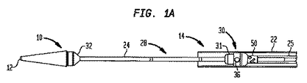
以下、本発明の構造および機能を説明するために、図1Aを参照すると、送達装置の第1の実施形態10は、遠位先端12、および遠位先端12から(図示されていない)近位端に延在するカテーテルアセンブリ14を有しており、該近位端は、ユーザが送達装置10を制御するための(図示されていない)ハンドルを備えている。送達装置10は、折畳み可能な人工心臓弁用の例示的な経大腿送達装置である。
Referring now to FIG. 1A to illustrate the structure and function of the present invention, a first embodiment 10 of a delivery device is proximal (not shown) from a distal tip 12 and from a distal tip 12. The
送達装置10は、経大腿送達装置であるが、本願に図示され、かつ記載されている本発明のリテーナは、経心尖送達装置(例えば、図2Aおよび図2Bに示されている装置10’)または折畳み可能なステント用の他の形式のチューブ状送達装置と共に用いられるように、構成されていてもよい。 While the delivery device 10 is a transfemoral delivery device, the retainer of the invention illustrated and described herein is a transapical delivery device (eg, the device 10 ′ shown in FIGS. 2A and 2B). Or it may be configured for use with other types of tubular delivery devices for collapsible stents.
カテーテルアセンブリ14は、ハンドルから遠位先端12に向かって延在するシース22、シース22の内側に配置されており、ハンドルから遠位先端12に延在する中空の内側シャフト24、および患者内に送達される人工弁を受容するように構成された弁受容区画28を備えている。
The
弁受容区画28は、折畳み可能な人工心臓弁を受容するように構成されている(例えば、折畳み可能な人工弁のステント部分が、図5A、図6A、および図7〜図10に示されている)。
弁受容区画28は、シース22の内側に配置されたリテーナ30、リテーナ30に隣接する近位円錐端31、およびリテーナ30から離間した遠位円錐端32を備えている。円錐端32は、弁受容区画28の一端において内側シャフト24に接合されており、円錐端31およびリテーナ30は、弁受容区画28の他端において内側シャフト24に取り付けられた補剛部材25に接合されている。好ましくは、内側シャフト24および補剛部材25は、(図示されていない)ガイドワイヤーを受け入れるように構成された同一の内径を有している。代替的に、本明細書に記載されている送達装置実施形態のいずれにおいても、内側シャフト24および補剛部材25は、単一体のシャフトであってもよい。患者内に送達するために、折畳み可能な弁が、弁受容区間29の円錐端31,32間に内側シャフト24を囲むように装填され、該弁のステント部分が、リテーナ30に連結されるようになっている。
The
The
図1Bを参照すると、リテーナ30は、外側片40、外側片40に隣接して配置された支持片42、および外側片40に該外側片40に対して回転可能となるように連結された内側片50を備えている。外側片40は、1つまたは複数の受入れ部36を画定している。各受入れ部36は、外側片40の保持縁34に配置されており、折畳み可能な弁のステント部分の対応する保持部材(例えば、図6Aの保持部材4参照)を受け入れるように構成されている。各受入れ部36は、好ましくは、従来のステント保持部材を受入れ部36との間にごくわずかな逃げを介在させて容易に捕捉するために、該ステント保持部材と同様の形状およびいくらか大きい寸法を有している。適切な形状および寸法を有する受入れ部36を形成することによって、例えば、展開または再鞘入れ手順における弁受容区画28内における弁の長手方向運動を阻止することができる。
Referring to FIG. 1B, the
図1Bに示されている実施形態では、外側片40および支持片42は、それらが内側片50に対して一緒に回転可能となるように、(例えば、溶着または任意の他の周知の接合技術によって)、一緒に取り付けられている。他の実施形態(例えば、図4に示されている実施形態)では、外側片および支持片は、互いに回転可能になっていてもよい。例えば、支持片は、外側片が支持片および内側片の両方に対して回転するように、内側片に取り付けられていてもよい。
In the embodiment shown in FIG. 1B, the
内側片50は、環状リング52を備えている。環状リング52は、外側片40内に画定された対応する周囲方向溝44内に嵌合するように、構成されている。リング52および溝44は、外側片40および支持片42が、内側片50の周りを自在に回転することができるが、内側片に対してそれほど大きく長手方向に摺動しないように、構成されている。図示されている実施形態では、外側片40と内側片42との間の摩擦制動力を最小限に抑えるために、これらの要素間にわずかな長手方向運動が許容されているが、リング52および溝44は、リテーナ30の使用中、外側片40および支持片42を内側片50上に保持している。
The inner piece 50 includes an
折畳み可能な人工弁を送達装置10に装填するために、ユーザは、人工弁のステント部分を外側片40に取付け、弁がシース22の内側に嵌め込まれるまで、弁を圧縮または圧着するようになっている。シース22は、ユーザが弁を展開することを決めるまで、該弁を圧縮状態で保持することになる。弁が後で鞘出しによって展開されると、ステントは、自己拡張し、最終的に外側片40から離脱する。もし弁が完全に展開されていないなら、すなわち、もし弁の一部がシース22の下に折り畳まれた状態でとどまっているなら、該弁は、シースを拡張されたステントの部分の上を後方に摺動させ、これによって、ステントの拡張された部分を再び折り畳むことによって、再鞘入れされるとよい。
To load the foldable prosthetic valve into the delivery device 10, the user attaches the stent portion of the prosthetic valve to the
弁が自然弁(例えば、患者の大動脈弁)を置換するために、患者内に経大腿的に送達されるかまたは径心尖的に送達されるかに関わらず、弁のステント部分は、好ましくは、ステントの(弁が配置されている端の反対側の)端から突出している保持部材(すなわち、ステントの大動脈側から突出している保持部材)によって、リテーナに取り付けられるようになっている。好ましくは、これらの保持部材は、最後に展開されることになる弁の端、すなわち、シースによって最も長く覆われていることになる弁の端に位置している。 Regardless of whether the valve is delivered transfemorally or radially into the patient to replace a natural valve (eg, a patient's aortic valve), the stent portion of the valve is preferably The retainer is attached to the retainer by a retention member protruding from the end of the stent (opposite the end where the valve is located) (ie, a retention member protruding from the aorta side of the stent). Preferably, these retaining members are located at the end of the valve that will be deployed last, that is, the end of the valve that will be covered the longest by the sheath.
例えば、経大腿人工大動脈弁送達装置(例えば、図1Aに示されている装置10)では、外側片40の保持縁34は、外側片の遠位端に配置されており、シース22が近位方向に移動され、弁を鞘出しかつ展開させ、これによって、弁の遠位端が最初に鞘出しされることになる。
For example, in a transfemoral prosthetic aortic valve delivery device (eg, the device 10 shown in FIG. 1A), the retaining
外側片40の保持縁34は、面取りした外縁を有しているとよく、これによって、ステントの鞘出しおよび再鞘入れ中、シース22と外側片40との間に作用する摩擦力の低減が助長されることになる。本明細書に開示されているリテーナ実施形態のいずれの保持縁も、面取りした外縁を有しているとよい。
The retaining
送達装置10が折畳み可能な弁を患者内に送達するのに用いられているとき、内側片50の周りを自在に回転する外側片40の能力によって、外側片40は、受入れ部36に連結されたステントによって受けた捩れ力を最小限に抑える周方向位置に、移動することが可能になる
When the delivery device 10 is used to deliver a foldable valve into a patient, the
例えば、送達装置10が、例えば、大動脈に向かって大腿動脈を通って、患者内を前進すると、人工弁のステント部分は、血管系を通る送達装置の移動によって、リテーナ30に対してその長軸の周りに捩じられ、これによって、ステントおよび受入れ部36に連結されたステントの保持部材の両方に捩れ応力が加えられることがある。しかし、外側片40が自在に回転するので、これらの捩れ応力は、外側片を内側片50およびシース22に対して回転させ、これによって、ステントおよびその保持部材に作用する捩れ力を解放することができる。
For example, when the delivery device 10 is advanced into the patient, for example, through the femoral artery towards the aorta, the stent portion of the prosthetic valve moves its long axis relative to the
図2Aを参照すると、送達装置の第2の実施形態10’は、遠位先端12、および遠位先端12から(図示されていない)近位端に延在するカテーテルアセンブリ14’を有しており、該近位端は、ユーザが送達装置10’を制御するための(図示されていない)ハンドルを備えている。送達装置10’は、折畳み可能な人工心臓弁用の例示的な経心尖送達装置である。 Referring to FIG. 2A, a second embodiment 10 'of the delivery device has a distal tip 12 and a catheter assembly 14' extending from the distal tip 12 to a proximal end (not shown). And the proximal end includes a handle (not shown) for the user to control the delivery device 10 '. Delivery device 10 'is an exemplary transapical delivery device for a foldable prosthetic heart valve.
カテーテルアセンブリ14’は、ハンドルから遠位先端12に向かって延在する近位シース20、遠位先端12からハンドルに向かって延在する遠位シース22’、近位端から近位シース20を通って摺動可能に延在しており、送達装置10’の遠位先端12において遠位シース22’に取り付けられた中空チューブ26、および患者の内側に送達される人工弁を受容するように構成された弁受容区画28’を備えている。
The catheter assembly 14 'includes a
弁受容区画28’は、折畳み可能な人工心臓弁を受容するように構成されている。弁受容区画28’は、近位シース20の遠位端における近位円錐端31’、近位円錐端から離間した遠位円錐端32’、および遠位円錐端32’に隣接して遠位シース22’の内側に配置されたリテーナ30’を備えている。中空内側シャフト24’は、その一端が近位円錐端31’に接続されており、その他端が遠位円錐端32’に接続されており、中空チューブ26を内部に摺動可能に受容している。患者内に送達するために、折畳み可能な弁は、弁受容区画28’の円錐端31’,32’間に内側シャフト24’を囲むように装填されており、弁のステント部分が、リテーナ30’に連結されている。
The valve receiving section 28 'is configured to receive a foldable prosthetic heart valve. The
図2Bを参照すると、リテーナ30’は、外側片40、外側片40に隣接して配置された支持片42、および外側片40に該外側片40に対して回転可能となるように連結された(図示されていないが、内側シャフト24’の外側に取り付けられている)内側片を備えている。外側片40は、1つまたは複数の受入れ部36を画定している。各受入れ部36は、外側片40の保持縁34に配置されており、折畳み可能な人工弁のステント部分の対応する保持部分を受け入れるように構成されている。各受入れ部36は、好ましくは、従来のステント保持部材を受入れ部36との間にごくわずかな逃げを介在させて容易に捕捉するために、該保持部材と同様の形状およびいくらか大きい寸法を有している。
Referring to FIG. 2B, the
経心尖人工大動脈弁送達装置(例えば、図2Aおよび図2Bに示されている装置10’)では、保持縁34は、外側片40の近位端に配置されており、遠位シース22’は、遠位方向に移動され、弁を鞘出しかつ展開させ、その結果、弁の近位端が最初に鞘出しされるようになっている。
In a transapical prosthetic aortic valve delivery device (eg, the device 10 'shown in FIGS. 2A and 2B), the retaining
図2Cを参照すると、図1Aに示されている送達装置10または図2Aに示されている送達装置10’に用いられるのに適するリテーナ30’’は、1つまたは複数の受入れ部36’’を有する代替的な外側片40’’を備えている。各受入れ部36’’は、外側片40’’の保持縁34に配置されており、折畳み可能な人工弁のステント部分の対応する保持部材を受け入れるように構成されている。
Referring to FIG. 2C, a
図1Aおよび図2Bに示されている受入れ部36と比較して、図2Cに示されている各受入れ部36’’は、保持縁34に近づくにつれて狭くなっている。具体的には、保持縁34から最も遠く離れている受入れ部36’の端は、保持縁34により近い受入れ部36’’の部分よりも広くなっている。図2Cに示されている受入れ部36’’のテーパ形状によって、ユーザは、図1Aおよび図2Bに示されている受入れ部36の形状と比較して、ステントの保持部材をリテーナ30’’内により容易に装填することができる。テーパ形状を有する受入れ部36’’は、本明細書に開示されているリテーナ実施形態のいずれに用いられてもよい。
Compared to the receiving
図3を参照すると、図1Aに示されている送達装置10に用いられるのに適するリテーナの他の実施形態30aは、内側片50aに該内側片50aに対して回転可能となるように連結された外側片40aを備えている。外側片40aは、1つまたは複数の受入れ部36を画定している。各受入れ部36は、外側片40aの保持縁34に配置されており、折畳み可能な弁のステント部分の対応する保持部材を受け入れるように構成されている。リテーナ30aは、中空内側シャフト24に取り付けられた補剛部材25に取り付けられている。
Referring to FIG. 3, another
リテーナ30aの外側片40aは、リテーナ30の外側片40と支持片42とを組み合わせた形状に似た形状を有している。内側片50aは、環状リング52aを備えている。環状リング52aは、外側片40a内に画定された対応する周方向溝44a内に嵌合するように構成されている。図1Bに示されているリテーナ30と同様、このリング・溝構造によって、外側片40aは、内側片50aの周りを自在に回転することができるが、内側片50aに対してそれほど大きく長手方向に摺動することができないようになっている。
The outer piece 40a of the
図4を参照すると、図1Aに示されている送達装置10に用いられるのに適するリテーナのさらに他の実施形態30bは、内側片50b、内側片に回転可能に連結された外側片40b、および外側片40bに隣接して配置されており、内側片に固定して連結された支持片42bを備えている。その結果、外側片40bが内側片50bに対して回転すると、外側片40bは、支持片42bに対しても回転することになる。外側片40bは、1つまたは複数の受入れ部36を備えている。各受入れ部36は、外側片の保持縁34に配置されており、折畳み可能な弁のステント部分の対応する保持部材を受け入れるように構成されている。リテーナ30bは、中空内部シャフト24に取り付けられた補剛部材25に取り付けられている。
Referring to FIG. 4, yet another
内側片50bは、環状リング52bを備えている。環状リング52bは、外側片40b内に画定された対応する周方向溝44b内に嵌合するように構成されている。図1Bに示されているリテーナ30と同様、リング52bおよび溝44bは、外側片40bが内側片50bの周りに自在に回転することができるが、内側片に対してそれほど大きく長手方向に摺動することができないように、構成されている。
The
図5Aおよび図5Bを参照すると、図1Aに示されている送達装置10に用いられるのに適するリテーナのさらに他の実施形態30cは、外側片40c、外側片40cに隣接して配置された支持片42c、および外側片40cに回転可能に連結された内側片50cを備えている。支持片42cは、内側片50cに対して回転可能となるように外側片40cに取り付けられていてもよいし、または外側片40cと支持片42cとの間に相対的な回転運動が生じるように、内側片50cに固定して取り付けられていてもよい。外側片40cは、1つまたは複数の受入れ部36cを備えている。各受入れ部36は、外側片40cの保持縁34に配置されている。
Referring to FIGS. 5A and 5B, yet another
図1Bに示されているリテーナ30と同様、リテーナ30cは、(図示されていない)リング・溝構造を備えており、このリング・溝構造によって、外側片40cは、内側片50cの周りを自在に回転することができるが、これらの2つの間のかなりの長手方向運動を阻止するようになっている。
Similar to the
折畳み可能な弁のステント部分1が、リテーナ30cに連結された状態で示されている。ステント部分1は、複数のステント支柱2を備えており、該支柱2は、それらの間にセル3を画定している。少なくとも1つの保持部材4が、ステント部分1の端から延在している。各保持部材4は、開口5を備えている。リテーナ30に対して前述したように、自然弁(例えば、患者の大動脈弁)を置換するために、弁が患者内に経心尖的に送達されるかまたは径大腿的に送達されるかに関わらず、該弁を含むステント1は、好ましくは、ステント1の(該弁が配置されている端の反対側の)端から突出している保持部材4(例えば、ステント1の大動脈側から突出している保持部材4)によって、リテーナ30cに取り付けられるようになっている。
The collapsible valve stent portion 1 is shown connected to a
リテーナ30cにおいて、受入れ部36c内の保持部材4の位置は、ユーザによって、長手方向に独立して調整可能になっている。すなわち、1つまたは複数の受入れ部36cは、ピン60を備えており、このピン60は、受入れ部内においてステント1の長手方向に手動によって摺動可能になっている。好ましくは、受入れ部36cの各々が、このような摺動可能なピン60を備えている。各ピン60は、アクチュエータワイヤー64に連結されている。アクチュエータワイヤー64は、ユーザがピンを縦長孔62に沿って摺動させることによって、独立して押し出されるかまたは引き込まれるようになっているとよい。ステント1の保持部材4は、該保持部材の開口5内に挿入されたピン60によって保持部材4を対応する受入れ部36c内に挿入することによって、リテーナ30cに連結されるようになっている。従って、対応するアクチュエータワイヤー64を近位側に引き込むかまた遠位側に押し出すことによって、ユーザは、各受入れ部36cのピン60の長手方向位置、従って、対応する保持部材4の長手方向位置を調整することができる。
In the
送達装置10が折畳み可能な弁を患者内に送達するために用いられているとき、該弁は、リテーナ30cおよびその受入れ部36cに対してある角度で傾けられることがあり、その結果、容易にそれらから離脱されないことがある。リテーナ30cに対する各保持部材4の長手方向位置を独立して調整する能力によって、該弁を送達装置10からの離脱を容易にするように真っ直ぐに延ばすことができる。
When the delivery device 10 is used to deliver a foldable valve into a patient, the valve may be tilted at an angle with respect to the
例えば、送達装置10が、大動脈に向かって大腿動脈を通って、患者内を前進すると、人工弁のステント部分は、血管系を通る送達装置の移動によって、リテーナ30cに対してその長軸を中心として捩れ、これによって、ステントおよび受入れ部36cに連結されたステントの保持部材の両方に対して捩れ応力が加えられることがある。しかし、外側片40cが自在に回転するので、これらの捩れ応力は、外側片を内側片50cおよびシース22に対して回転させ、これによって、ステントおよびその保持部材に作用している捩れ力を解放することができる。もしユーザが、(弁の十分な展開を妨げるかまたは保持部材4を損傷させる可能性のある)ステント1に蓄積されている応力またはリテーナ30cに対するステント1の位置ずれを検出したなら、ユーザは、リテーナ30cおよびその受入れ部36cに対して1つまたは複数の保持部材4の長手方向位置を独立して調整し、これによって、ステントを再調整し、弁を連続的に離脱させることができる。
For example, as the delivery device 10 is advanced through the femoral artery and into the patient toward the aorta, the stent portion of the prosthetic valve is centered about its long axis relative to the
受入れ部36c内の保持部材4の位置を長手方向に沿って独立して調整する能力を有するリテーナ30cが、図1A〜図5Bに示されている回転可能なリテーナ実施形態を参照して、図示されかつ記載されているが、受入れ部36c内の保持部材4の位置を長手方向に独立して調整する能力は、受入れ部の長さが長手方向においてそれぞれの保持部材の長さよりも大きい特徴を備えている、図6A〜図10に示されている実施形態に組み入れられてもよい。
A
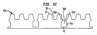
図6A〜図6Cを参照すると、図1Aおよび図2Aに示されている送達装置10,10’に用いられるのに適するリテーナのさらに他の実施形態30dは、内側片50d、内側片に回転可能に連結された外側片40d、および外側片40dに隣接して内側片に連結された支持片42dを備えている。支持片42dは、内側片50dに対して回転可能となるように外側片40dに取り付けられていてもよいし、または外側片40dと支持片42dとの間に相対的な回転運動が生じるように、内側片50dに固定して取り付けられていてもよい。内側片50dに対して自在に回転する外側片40dの能力によって、図1〜図5の実施形態に対して前述した有利なステント応力緩和効果が得られることになる。
With reference to FIGS. 6A-6C, yet another
外側片40dは、内側片50dに回転可能に連結されているものとして、ここに記載されているが、いくつかの実施形態では、外側片40dは、内側片50dに固定されていてもよい。リテーナ30dの他の特徴部(例えば、凹部38)は、外側片40dが内側片50dに対して固定されている実施形態に含まれていてもよいし、または外側片40dが内側片50dに対して回転可能になっている実施形態に含まれていてもよい。同様に、図7〜図10に示されている外側片は、これらの図に示されている対応する内側片に対して固定されていてもよいし、または回転可能になっていてもよい。
Although the
図1Aに示されている装置10のような経大腿送達装置では、リテーナ30dは、送達装置の内側シャフト24への連結に適する近位円錐端31dに隣接して配置されているとよい。一方、図2Aに示されている装置10’のような経心尖送達装置では、リテーナ30dは、送達装置の内側シャフト24’への連結に適する遠位円錐端32dに隣接して配置されているとよい。
In a transfemoral delivery device, such as the device 10 shown in FIG. 1A, the
外側片40dは、1つまたは複数の受入れ部36dを備えている。各受入れ部36dは、外側片40dの保持縁34から延在しており、折畳み可能な人工弁のステント部分の対応する保持部材4を受け入れるように構成されている。各受入れ部36dは、細長形状を有しており、狭小ネック39dを画定するように互いに向かって突出する突起37dを備えている。狭小ネック39dは、保持縁34に向かう対応する保持部材4の長手方向運動を制限するものである。ネック39dは、保持縁34から離間したポケット41dを画定するように、受入れ部36d内に配置されている。図6Aから分かるように、ポケット41dは、保持部材4の大きさよりも実質的に大きい長手方向の長さを有している。
The
3つの受入れ部36dが図6Cの実施形態に示されているが、リテーナ30d(および本明細書に開示されている他のリテーナの全て)は、任意の数の受入れ部、例えば、1つ、2つ、4つ、6つ、または8つの受入れ部を有していてもよい。さらに、各受入れ部36d(および本明細書に開示されている他の受入れ部の全て)は、ネック39dを画定する単一突起37dまたは2つよりも多い任意の数の突起を有していてもよい。3つの保持部材4が、この実施形態(および本明細書に記載されている他の実施形態)において、3つの受入れ部36dにそれぞれ係合するように記載されているが、本明細書に記載されているリテーナは、任意の数の保持部材4、例えば、1つ、2つ、4つ、6つ、または8つの保持部材を有するステント1に用いられてもよい。
Although three
外側片40dは、1つまたは複数の凹部38をさらに備えている。凹部38は、保持縁34から内方に延在しており、ステント1の端において支柱2によって形成されたV字状接合部を受け入れるように構成されている。凹部38は、保持縁34に対する対応するステント支柱2の長手方向運動を制限するものである。さらに、凹部38は、ステント支柱2の周方向位置を固定し、人工弁の送達および展開中にステント支柱2が互いに重なって絡まるのを阻止するものである。
The
図6Aに示されているように人工弁がリテーナ30dに組み込まれると、保持部材4は、ポケット41dの端壁43から離間することになる。しかし、もし人工弁をリテーナ30dに対して押し出す傾向にある長手方向力が生じたなら、凹部38内のステント支柱2の係合によって、リテーナに対する人工弁の長手方向運動が阻止されることになる。その結果、保持部材4は、ポケット41dの端壁43から離間して維持され、人工弁のステント1とリテーナ30dとの間の圧縮力は、保持部材に局在されず、むしろ、ステント支柱2を介してステントの周囲に実質的に均一に分配されることになる。以上の説明を考慮すれば、凹部38は、図6Cに示されているように略U字状であってもよいし、または対応するステント支柱2を受け入れ、前述した目的を果たすどのような他の形状を有していてもよいことを理解されたい。
When the artificial valve is incorporated into the
図1Bに示されているリテーナ30と同じように、リテーナ30dは、環状リング・溝構成を備えており、該構成によって、外側片40dは、内側片50dの周りに自在に回転することができるが、内側片に対して長手方向に移動することが阻止されるようになっている。
Similar to the
折畳み可能な弁を患者の所望の箇所内に展開するためのステント1の鞘出し中に、リテーナ30dの凹部38は、リテーナとステントとの間に作用する力を、保持部材4自体に向けるよりはむしろ、前述したように保持部材4を支持していないステント支柱2に向けるようになっている。その結果、これらの力は、ステント1の周囲により均一に分配されることになる。これによって、保持部材4または保持部材4を支持するステント支柱2が損傷または変形するのを阻止することができる。
During the sheathing of the stent 1 for deploying the foldable valve into the desired location of the patient, the
例えば、人工弁の鞘出しは、シース22または22’(図1A,2A参照)とステント1との間に摩擦力を生じさせ、これによって、ステント1をリテーナ30dに対して長手方向に押し出すかまたは引き出すことになる。この長手方向力は、ステント支柱2を凹部38の底に強制的に係合させ、その一方、保持部材4は、ポケット41dの端43から離間して維持されており、これによって、保持部材に押圧力が加えられるのが阻止されることになる。
For example, prosthetic valve sheathing creates a frictional force between the
人工弁の再鞘入れ中にも、例えば、ユーザが患者内の弁の位置を調整する必要があると判断したときの人工弁の再鞘入れ中にも、摩擦力がシース22または22’とステント1との間に生じるが、この摩擦力は、ステント1をリテーナ30dから離脱させるように押し出すかまたは引き出すように加えられる傾向にある。このような場合、保持部材4は、突起37によってポケット41dの端からさらに離れるように移動しないように阻止されることになる。
Frictional forces may also occur with the
リテーナのさらに他の実施形態30eが、図7に示されている。リテーナ30eは、図1Aおよび図2Aにそれぞれ示されている送達装置10,10’に用いられるのに適している。リテーナ30eは、前述のリテーナ30dと実質的に同じである。しかし、リテーナ30dの端壁43のようにリテーナ縁34から離れたポケット41eの端に端壁を有しておらず、ポケット41eは、開端を有している。前述の説明から、保持部材4は、人工弁を展開または再鞘入れのための展開装置の使用中に、リテーナ30dの端壁43に接触しないことを理解されたい。従って、端壁43は、必要ではなく、リテーナ30eから削除されている。
Yet another
図8は、図1Aおよび図2Aにそれぞれ示されている送達装置10,10’に用いられるのに適するリテーナのさらに他の実施形態30fを示している。リテーナ30fは、保持縁34から内方に延在する凹部38が削除されていることを除けば、前述のリテーナ30eと実質的に同様である。従って、リテーナ30fでは、患者内の人工弁の鞘出しまたは展開中、外側片40fの保持縁34が、ステント支柱2の長手方向運動に制限をもたらすことになる。しかし、保持縁34がステント支柱2を個別に捕捉していないので、リテーナ30fは、人工弁を送達および展開するための送達装置の使用中に、ステント支柱が互いに重なって、絡まるのを阻止することができない。
FIG. 8 shows yet another
リテーナのさらに他の実施形態30gが、図9に示されている。リテーナ30gは、図1Aおよび図2Aにそれぞれ示されている送達装置10,10’に用いられるのに適している。リテーナ30gは、前述のリテーナ30d,30eと実質的に同じであるが、外側片40gの構成、特に受入れ部36gの構成において異なっている。受入れ部36d,36eのように、周方向において保持部材4に密接に嵌合されるようになっているが、長手方向において過度の自由空間を有するようになっておらず、受入れ部36gは、長手方向および周方向の両方において、大きめの寸法を有している。この点について、受入れ部36gは、周方向において、保持部材4の周方向寸法に対する任意の倍率、例えば、1.5倍、3倍、または4倍だけ、保持部材4に対して大きくなっているとよい。保持部材4の対応する寸法の少なくとも約2倍の周方向寸法が、好ましい。受入れ部36gの寸法が大きくなっていることによって、弁受容区画28または28’内への人工弁のステント部分の組込みが容易になり、また保持部材4が受入れ部から離脱できない可能性を最小限に抑えることによって、人工弁の展開が容易になる。
Yet another
送達装置10,10’に用いられるのに適するリテーナの他の実施形態30hが、図10に示されている。リテーナ30hは、前述のリテーナ30fと同様であるが、該リテーナ30fの特徴を前述のリテーナ30gの特徴と組み合わせている。すなわち、リテーナ30hは、リテーナ30fと同じように、内方に延在する凹部38が設けられていない保持縁34を有している。従って、人工弁の鞘出しまたは展開中、外側片40hの保持縁34が、ステント支柱2の長手方向運動を制限することになる。しかし、リテーナ30hは、リテーナ30fにおけるように、周方向において保持部材4と密接に嵌合する受入れ部を有しておらず、人工弁がリテーナに組み込まれたときに保持部材4間に存在するどのような構造も本質的に省かれている、単一の受入れ領域を有している。従って、リテーナ30hでは、周方向においてリテーナに対する人工弁の位置を固定する唯一の構造体は、保持縁34から受入れ領域36hに延在するネック39hである。にもかかわらず、保持縁34に対するステント支柱2の係合およびネック39hに対する保持部材4の係合によって、リテーナ30hに対する人工弁の長手方向運動を実質的に阻止することができる。
Another
本明細書では、折畳み可能なステント構造を有する人工弁の展開に対する保持に関連して、種々のリテーナ実施形態を説明してきたが、これらのリテーナ実施形態は、いずれも、他の目的に用いられてもよい。具体的には、これらの種々のリテーナ実施形態は、弁を含まない従来の折畳み可能なステントを保持するのに用いられてもよい。 Although various retainer embodiments have been described herein in connection with retention against deployment of a prosthetic valve having a collapsible stent structure, any of these retainer embodiments may be used for other purposes. May be. Specifically, these various retainer embodiments may be used to hold a conventional foldable stent that does not include a valve.
本明細書では、人工弁の弁輪端が最初に展開される特定の実施形態を参照して、本発明を説明してきたが、本発明は、弁の大動脈端が最初に展開される実施形態も考慮していることを理解されたい。(図示されていない)このような実施形態では、保持部材は、送達装置のリテーナと係合するために、弁のステント部分の弁輪端から突出するようになっているとよく、これによって、ステントの大動脈端は、リテーナから離れて位置することになるので、最初に鞘出しされることになる。(図示されていない)さらに他の実施形態では、保持部材は、リテーナと係合するために、弁のステントの大動脈端および弁輪端の両方から突出するようになっていてもよい。 Although the present invention has been described herein with reference to a particular embodiment in which the annulus end of the prosthetic valve is first deployed, the present invention is an embodiment in which the aortic end of the valve is first deployed. It should be understood that this also takes into account. In such an embodiment (not shown), the retention member may be adapted to protrude from the annulus end of the stent portion of the valve for engagement with the retainer of the delivery device, whereby Since the aortic end of the stent will be located away from the retainer, it will be sheathed first. In yet another embodiment (not shown), the retention member may protrude from both the aortic end and the annulus end of the valve stent to engage the retainer.
本明細書では、本発明を特定の実施形態を参照して説明してきたが、これらの実施形態は、本発明の原理および応用の単なる例示にすぎないことを理解されたい。従って、多くの修正が例示的な実施形態に対してなされてもよいこと、および添付の請求項に記載の本発明の精神および範囲から逸脱することなく、他の構成が考案されてもよいことを理解されたい。 Although the invention herein has been described with reference to particular embodiments, it is to be understood that these embodiments are merely illustrative of the principles and applications of the present invention. Accordingly, many modifications may be made to an exemplary embodiment and other configurations may be devised without departing from the spirit and scope of the invention as set forth in the appended claims. I want you to understand.
種々の従属請求項および本明細書に記載されている特徴部は、元の請求項に記載されているのと異なる方式で組み込まれてもよいことを理解されたい。また、個々の実施形態に関連して記載されている特徴は、記載されている実施形態の他のものと共有されてもよいことも理解されたい。 It should be understood that the various dependent claims and the features described in this specification may be incorporated in a manner different from that described in the original claims. It should also be understood that the features described in connection with individual embodiments may be shared with others in the described embodiments.
Claims (14)
長手方向に延在しているシャフトと、
前記シャフトの長手方向部分を囲んでいる細長シースであって、前記シャフトに対して長手方向に摺動可能になっている細長シースと、
前記シースの内側に画定され、組立状態にある前記医学装置を受容するように構成された区画と、
前記区画の一端に配置されたリテーナであって、内側片と、前記内側片の周りに回転可能となるように、かつ前記内側片に対して長手方向における運動が制約されるように、前記内側片上に取り付けられた外側片とを備えているリテーナと、
前記組立状態にある前記医学装置の前記保持部材を受け入れるように構成された、前記リテーナ内の少なくとも1つの受入れ部と、
を備え、
前記外側片は、前記区画と向き合った保持縁を有しており、前記受入れ部は、前記保持部材を受け入れるように寸法決めされた第1の領域を有しており、前記受入れ部は、前記第1の領域と前記保持縁との間に狭小ネックを画定する少なくとも1つの突起を備えていることを特徴とする送達装置。 In the delivery device for implantable medical devices having at one end a single holding member even without low, the delivery device,
A shaft extending in the longitudinal direction;
An elongate sheath surrounding a longitudinal portion of the shaft, the elongate sheath being slidable in the longitudinal direction relative to the shaft;
A compartment defined inside the sheath and configured to receive the assembled medical device;
A retainer disposed at one end of the compartment, wherein the inner piece is configured to be rotatable about the inner piece and the inner piece such that longitudinal movement is constrained relative to the inner piece. A retainer comprising an outer piece mounted on the piece;
At least one receiving portion in the retainer configured to receive the retaining member of the medical device in the assembled state;
With
The outer piece has a retaining edge facing the compartment, and the receiving portion has a first region sized to receive the holding member, the receiving portion being A delivery device comprising at least one protrusion defining a narrow neck between a first region and the retaining edge.
前記区画内に組み込まれた移植可能な医学装置であって、前記医学装置は、その一端に少なくとも1つの保持部材を有しており、前記保持部材は、前記受入れ部内に配置されている医学装置をさらに備えていることを特徴とするシステム。 A system comprising the delivery device of claim 1, wherein the system is
An implantable medical device incorporated in the compartment, the medical device having at least one holding member at one end thereof, the holding member being disposed in the receiving part system characterized in that it further comprises a.
前記ピンに連結されたアクチュエータであって、前記ピンを長手方向に移動させるように構成されており、これによって、前記受入れ部に対する前記保持部材の長手方向位置を調整するようになっているアクチュエータと、
をさらに備えていることを特徴とする、請求項4に記載のシステム。 A pin extending radially outward from the at least one receiving portion and engaged with an opening of the retaining member;
An actuator coupled to the pin, the actuator configured to move the pin in a longitudinal direction, thereby adjusting a longitudinal position of the holding member relative to the receiving portion; ,
The system of claim 4 further comprising:
前記ピンに連結されたアクチュエータであって、前記ピンを長手方向に移動させるように構成されており、これによって、前記受入れ部に対する前記保持部材の長手方向位置を調整するようになっているアクチュエータと、
をさらに備えていることを特徴とする、請求項1または10に記載の送達装置。 A pin extending radially outward from the at least one receiving portion and configured to engage an opening of the holding member;
An actuator coupled to the pin, the actuator configured to move the pin in a longitudinal direction, thereby adjusting a longitudinal position of the holding member relative to the receiving portion; ,
The delivery device according to claim 1, further comprising:
Applications Claiming Priority (3)
| Application Number | Priority Date | Filing Date | Title |
|---|---|---|---|
| US36445310P | 2010-07-15 | 2010-07-15 | |
| US61/364,453 | 2010-07-15 | ||
| PCT/US2011/001218 WO2012009006A1 (en) | 2010-07-15 | 2011-07-12 | Retainers for transcatheter heart valve delivery systems |
Publications (3)
| Publication Number | Publication Date |
|---|---|
| JP2013534452A JP2013534452A (en) | 2013-09-05 |
| JP2013534452A5 JP2013534452A5 (en) | 2014-08-21 |
| JP5906239B2 true JP5906239B2 (en) | 2016-04-20 |
Family
ID=44533048
Family Applications (1)
| Application Number | Title | Priority Date | Filing Date |
|---|---|---|---|
| JP2013519648A Expired - Fee Related JP5906239B2 (en) | 2010-07-15 | 2011-07-12 | Retainer for transcatheter heart valve delivery system |
Country Status (8)
| Country | Link |
|---|---|
| US (1) | US9119717B2 (en) |
| EP (1) | EP2593048B1 (en) |
| JP (1) | JP5906239B2 (en) |
| AU (1) | AU2011279727B2 (en) |
| BR (1) | BR112013001024A2 (en) |
| CR (1) | CR20130017A (en) |
| ES (1) | ES2478515T3 (en) |
| WO (1) | WO2012009006A1 (en) |
Families Citing this family (71)
| Publication number | Priority date | Publication date | Assignee | Title |
|---|---|---|---|---|
| US9414914B2 (en) * | 2010-02-24 | 2016-08-16 | Medtronic Ventor Technologies Ltd. | Catheter assembly with valve crimping accessories |
| US8579964B2 (en) | 2010-05-05 | 2013-11-12 | Neovasc Inc. | Transcatheter mitral valve prosthesis |
| US9387077B2 (en) * | 2010-05-27 | 2016-07-12 | Medtronic Vascular Galway | Catheter assembly with prosthesis crimping and prosthesis retaining accessories |
| WO2012023980A1 (en) | 2010-08-17 | 2012-02-23 | St. Jude Medical, Inc. | Sleeve for facilitating movement of a transfemoral catheter |
| CN106073946B (en) | 2010-09-10 | 2022-01-04 | 西美蒂斯股份公司 | Valve replacement device, delivery device for a valve replacement device and method of producing a valve replacement device |
| BR112013006302A2 (en) | 2010-09-17 | 2016-06-07 | St Jude Medical Cardiology Div | placement device for a collapsible prosthetic heart valve, and method for placing a collapsible prosthetic heart valve |
| US9554897B2 (en) | 2011-04-28 | 2017-01-31 | Neovasc Tiara Inc. | Methods and apparatus for engaging a valve prosthesis with tissue |
| US9308087B2 (en) | 2011-04-28 | 2016-04-12 | Neovasc Tiara Inc. | Sequentially deployed transcatheter mitral valve prosthesis |
| EP2736450A1 (en) | 2011-07-28 | 2014-06-04 | St. Jude Medical, Inc. | Expandable radiopaque marker for transcatheter aortic valve implantation |
| US9668859B2 (en) | 2011-08-05 | 2017-06-06 | California Institute Of Technology | Percutaneous heart valve delivery systems |
| US9277990B2 (en) | 2012-05-04 | 2016-03-08 | St. Jude Medical, Cardiology Division, Inc. | Hypotube shaft with articulation mechanism |
| US9532871B2 (en) | 2012-05-04 | 2017-01-03 | St. Jude Medical, Cardiology Division, Inc. | Delivery system deflection mechanism |
| US9345573B2 (en) | 2012-05-30 | 2016-05-24 | Neovasc Tiara Inc. | Methods and apparatus for loading a prosthesis onto a delivery system |
| US9480561B2 (en) | 2012-06-26 | 2016-11-01 | St. Jude Medical, Cardiology Division, Inc. | Apparatus and method for aortic protection and TAVI planar alignment |
| US9918837B2 (en) * | 2012-06-29 | 2018-03-20 | St. Jude Medical, Cardiology Division, Inc. | System to assist in the release of a collapsible stent from a delivery device |
| US9510946B2 (en) * | 2012-09-06 | 2016-12-06 | Edwards Lifesciences Corporation | Heart valve sealing devices |
| US9687373B2 (en) * | 2012-12-21 | 2017-06-27 | Cook Medical Technologies Llc | Systems and methods for securing and releasing a portion of a stent |
| CN103083122B (en) * | 2013-01-21 | 2015-11-04 | 北京华脉泰科医疗器械有限公司 | A kind of fixture of overlay film frame |
| CN103126739B (en) * | 2013-01-31 | 2016-05-04 | 北京华脉泰科医疗器械有限公司 | A kind of conveying device of overlay film frame |
| US11793636B2 (en) | 2013-02-06 | 2023-10-24 | Symetis Sa | Prosthetic valve. delivery apparatus and delivery method |
| EP2953579B1 (en) | 2013-02-06 | 2017-05-31 | Symetis SA | A delivery catheter for a prosthetic valve |
| US10105220B2 (en) | 2013-02-21 | 2018-10-23 | St. Jude Medical, Cardiology Division, Inc. | Transapical passive articulation delivery system design |
| US11331208B2 (en) * | 2013-03-05 | 2022-05-17 | Cook Medical Technologies Llc | Inner catheter with a pusher band |
| US9339385B2 (en) * | 2013-03-07 | 2016-05-17 | St. Jude Medical, Cardiology Division, Inc. | Balloon release mechanism for TAVI implant |
| WO2014144247A1 (en) | 2013-03-15 | 2014-09-18 | Arash Kheradvar | Handle mechanism and functionality for repositioning and retrieval of transcatheter heart valves |
| US20140277341A1 (en) * | 2013-03-15 | 2014-09-18 | Cook Medical Technologies Llc | Wireless medical device release mechanism |
| US9572665B2 (en) | 2013-04-04 | 2017-02-21 | Neovasc Tiara Inc. | Methods and apparatus for delivering a prosthetic valve to a beating heart |
| US9566153B2 (en) | 2013-09-12 | 2017-02-14 | St. Jude Medical, Cardiology Division, Inc. | Alignment of an implantable medical device |
| EP3043755B1 (en) | 2013-09-12 | 2022-10-19 | St. Jude Medical, Cardiology Division, Inc. | Atraumatic interface in an implant delivery device |
| WO2015038458A1 (en) | 2013-09-12 | 2015-03-19 | St. Jude Medical, Cardiology Division, Inc. | Stent designs for prosthetic heart valves |
| WO2015077274A1 (en) | 2013-11-19 | 2015-05-28 | St. Jude Medical, Cardiology Division, Inc. | Sealing structures for paravalvular leak protection |
| US9820852B2 (en) | 2014-01-24 | 2017-11-21 | St. Jude Medical, Cardiology Division, Inc. | Stationary intra-annular halo designs for paravalvular leak (PVL) reduction—active channel filling cuff designs |
| US20150209141A1 (en) | 2014-01-24 | 2015-07-30 | St. Jude Medical, Cardiology Division, Inc. | Stationary intra-annular halo designs for paravalvular leak (pvl) reduction-passive channel filling cuff designs |
| WO2015152980A1 (en) | 2014-03-31 | 2015-10-08 | St. Jude Medical, Cardiology Division, Inc. | Paravalvular sealing via extended cuff mechanisms |
| US9433520B2 (en) | 2015-01-29 | 2016-09-06 | Intact Vascular, Inc. | Delivery device and method of delivery |
| US9375336B1 (en) | 2015-01-29 | 2016-06-28 | Intact Vascular, Inc. | Delivery device and method of delivery |
| DE102015103240A1 (en) * | 2015-03-05 | 2016-09-08 | Phenox Gmbh | implant delivery |
| US10531954B2 (en) * | 2015-03-20 | 2020-01-14 | St. Jude Medical, Cardiology Division, Inc. | Mitral valve loading tool |
| EP3349670B1 (en) * | 2015-09-18 | 2020-09-09 | Microvention, Inc. | Releasable delivery system |
| US11033387B2 (en) | 2015-11-23 | 2021-06-15 | Edwards Lifesciences Corporation | Methods for controlled heart valve delivery |
| US10265169B2 (en) * | 2015-11-23 | 2019-04-23 | Edwards Lifesciences Corporation | Apparatus for controlled heart valve delivery |
| US10420661B2 (en) * | 2015-12-17 | 2019-09-24 | Covidien Lp | Stents and stent deployment devices |
| CN106913408B (en) * | 2015-12-28 | 2018-10-26 | 先健科技(深圳)有限公司 | Transport system and intraluminal stent system |
| US10993824B2 (en) | 2016-01-01 | 2021-05-04 | Intact Vascular, Inc. | Delivery device and method of delivery |
| US10433952B2 (en) | 2016-01-29 | 2019-10-08 | Neovasc Tiara Inc. | Prosthetic valve for avoiding obstruction of outflow |
| JP6724490B2 (en) * | 2016-03-31 | 2020-07-15 | 日本ゼオン株式会社 | Stent delivery system |
| EP3454794B1 (en) | 2016-05-13 | 2021-04-14 | St. Jude Medical, Cardiology Division, Inc. | Systems for device implantation |
| DE102016111323A1 (en) * | 2016-06-21 | 2017-12-21 | Biotronik Ag | Insertion catheter and catheter assembly |
| AU2017361296B2 (en) | 2016-11-21 | 2022-09-29 | Neovasc Tiara Inc. | Methods and systems for rapid retraction of a transcatheter heart valve delivery system |
| US10561495B2 (en) | 2017-01-24 | 2020-02-18 | 4C Medical Technologies, Inc. | Systems, methods and devices for two-step delivery and implantation of prosthetic heart valve |
| US10675017B2 (en) | 2017-02-07 | 2020-06-09 | Edwards Lifesciences Corporation | Transcatheter heart valve leaflet plication |
| US10660752B2 (en) | 2017-03-16 | 2020-05-26 | St. Jude Medical, Cardiology Division, Inc. | Retainers for transcatheter heart valve delivery systems |
| US10842619B2 (en) | 2017-05-12 | 2020-11-24 | Edwards Lifesciences Corporation | Prosthetic heart valve docking assembly |
| CA3068313A1 (en) | 2017-06-30 | 2019-01-03 | Edwards Lifesciences Corporation | Docking stations for transcatheter valves |
| CN110891526A (en) | 2017-06-30 | 2020-03-17 | 爱德华兹生命科学公司 | Locking and releasing mechanism for transcatheter implantable devices |
| US11660218B2 (en) | 2017-07-26 | 2023-05-30 | Intact Vascular, Inc. | Delivery device and method of delivery |
| US10856984B2 (en) | 2017-08-25 | 2020-12-08 | Neovasc Tiara Inc. | Sequentially deployed transcatheter mitral valve prosthesis |
| CN111163703B (en) * | 2017-10-12 | 2023-12-15 | 克里斯托夫梅斯克两合公司 | Pericardial clamp and method for implantation of temporary heart assist system |
| US10932931B2 (en) * | 2018-03-13 | 2021-03-02 | Medtronic Vascular, Inc. | Medical device delivery system including a support member |
| US11857441B2 (en) | 2018-09-04 | 2024-01-02 | 4C Medical Technologies, Inc. | Stent loading device |
| CA3118599A1 (en) | 2018-11-08 | 2020-05-14 | Neovasc Tiara Inc. | Ventricular deployment of a transcatheter mitral valve prosthesis |
| US11602429B2 (en) | 2019-04-01 | 2023-03-14 | Neovasc Tiara Inc. | Controllably deployable prosthetic valve |
| AU2020271896B2 (en) | 2019-04-10 | 2022-10-13 | Neovasc Tiara Inc. | Prosthetic valve with natural blood flow |
| EP3972673A4 (en) | 2019-05-20 | 2023-06-07 | Neovasc Tiara Inc. | Introducer with hemostasis mechanism |
| IT201900007890A1 (en) * | 2019-06-03 | 2020-12-03 | Heartpoint Global Ltd | Self-expanding stent applicator device |
| WO2020257643A1 (en) | 2019-06-20 | 2020-12-24 | Neovasc Tiara Inc. | Low profile prosthetic mitral valve |
| CN113017951A (en) | 2019-12-24 | 2021-06-25 | 上海微创心通医疗科技有限公司 | Implant conveying device, inner tube assembly and catheter thereof |
| US11931253B2 (en) | 2020-01-31 | 2024-03-19 | 4C Medical Technologies, Inc. | Prosthetic heart valve delivery system: ball-slide attachment |
| US20220079753A1 (en) * | 2020-09-17 | 2022-03-17 | Half Moon Medical, Inc. | Delivery systems for cardiac valve devices, and associated methods of operation |
| US20230390056A1 (en) * | 2022-06-06 | 2023-12-07 | St. Jude Medical, Cardiology Division, Inc. | Balloon Expandable Valve Securement Aids |
| EP4309625A1 (en) * | 2022-07-20 | 2024-01-24 | Creganna Unlimited Company | Socket for a prosthetic aortic valve delivery device, device for delivering a prosthetic aortic valve, and method of configuring a device for selective prosthetic aortic valve orientation |
Family Cites Families (40)
| Publication number | Priority date | Publication date | Assignee | Title |
|---|---|---|---|---|
| DE69419877T2 (en) * | 1993-11-04 | 1999-12-16 | Bard Inc C R | Fixed vascular prosthesis |
| DE69534065T2 (en) | 1994-12-27 | 2005-09-15 | Advanced Cardiovascular Systems, Inc., Santa Clara | CATHETER WITH REINFORCED LONG-SECTION CROSS-SECTION |
| US5797952A (en) * | 1996-06-21 | 1998-08-25 | Localmed, Inc. | System and method for delivering helical stents |
| GB9706766D0 (en) | 1997-04-03 | 1997-05-21 | Sulzer Vascutek Ltd | Endovascular prostheses |
| US6776791B1 (en) * | 1998-04-01 | 2004-08-17 | Endovascular Technologies, Inc. | Stent and method and device for packing of same |
| US6214036B1 (en) * | 1998-11-09 | 2001-04-10 | Cordis Corporation | Stent which is easily recaptured and repositioned within the body |
| US6623518B2 (en) | 2001-02-26 | 2003-09-23 | Ev3 Peripheral, Inc. | Implant delivery system with interlock |
| US6814746B2 (en) * | 2002-11-01 | 2004-11-09 | Ev3 Peripheral, Inc. | Implant delivery system with marker interlock |
| US7771463B2 (en) * | 2003-03-26 | 2010-08-10 | Ton Dai T | Twist-down implant delivery technologies |
| US7473271B2 (en) * | 2003-04-11 | 2009-01-06 | Boston Scientific Scimed, Inc. | Stent delivery system with securement and deployment accuracy |
| US20040267348A1 (en) * | 2003-04-11 | 2004-12-30 | Gunderson Richard C. | Medical device delivery systems |
| US7235093B2 (en) * | 2003-05-20 | 2007-06-26 | Boston Scientific Scimed, Inc. | Mechanism to improve stent securement |
| US8337543B2 (en) | 2004-11-05 | 2012-12-25 | Boston Scientific Scimed, Inc. | Prosthesis anchoring and deploying device |
| DE102004062296A1 (en) | 2004-12-23 | 2006-07-06 | Strecker, Ernst Peter, Prof. Dr.med. | Device for positioning a stent |
| EP3266414A1 (en) * | 2005-05-12 | 2018-01-10 | Covidien LP | Implant delivery system with interlocked rx port orientation |
| US20070016243A1 (en) | 2005-06-28 | 2007-01-18 | Venkatesh Ramaiah | Non-occlusive, retrievable dilation system |
| US8790396B2 (en) | 2005-07-27 | 2014-07-29 | Medtronic 3F Therapeutics, Inc. | Methods and systems for cardiac valve delivery |
| US7749266B2 (en) | 2006-02-27 | 2010-07-06 | Aortx, Inc. | Methods and devices for delivery of prosthetic heart valves and other prosthetics |
| EP2353553B1 (en) | 2006-05-12 | 2015-12-02 | Covidien LP | Implant and delivery system with multiple marker interlocks |
| CA2998123C (en) | 2006-09-08 | 2021-03-02 | Edwards Lifesciences Corporation | Integrated heart valve delivery system |
| US7655034B2 (en) * | 2006-11-14 | 2010-02-02 | Medtronic Vascular, Inc. | Stent-graft with anchoring pins |
| JP5319546B2 (en) * | 2006-12-15 | 2013-10-16 | カーディオマインド, インコーポレイテッド | Stent system |
| JP5604110B2 (en) | 2007-02-05 | 2014-10-08 | ボストン サイエンティフィック リミテッド | System for delivering a valve |
| DE102007012964A1 (en) * | 2007-03-06 | 2008-09-11 | Phenox Gmbh | Implant for influencing blood flow |
| GB0722192D0 (en) | 2007-11-12 | 2007-12-19 | Angiomed Gmbh & Co | Elongate medical device |
| EP2240121B1 (en) | 2008-01-16 | 2019-05-22 | St. Jude Medical, Inc. | Delivery and retrieval systems for collapsible/expandable prosthetic heart valves |
| CA2961051C (en) | 2008-02-29 | 2020-01-14 | Edwards Lifesciences Corporation | Expandable member for deploying a prosthetic device |
| US8992591B2 (en) | 2008-05-07 | 2015-03-31 | Cook Medical Technologies Llc | Delivery system with low longitudinal compressibility |
| CN107961098A (en) | 2008-06-30 | 2018-04-27 | 波顿医疗公司 | System and method for abdominal aneurvsm |
| US8652202B2 (en) * | 2008-08-22 | 2014-02-18 | Edwards Lifesciences Corporation | Prosthetic heart valve and delivery apparatus |
| CA2743719C (en) | 2008-11-25 | 2019-03-19 | Edwards Lifesciences Corporation | Apparatus and method for in situ expansion of prosthetic device |
| CA2961053C (en) * | 2009-04-15 | 2019-04-30 | Edwards Lifesciences Cardiaq Llc | Vascular implant and delivery system |
| AU2010286587B2 (en) | 2009-08-27 | 2013-10-17 | Medtronic Inc. | Transcatheter valve delivery systems and methods |
| US20110077731A1 (en) | 2009-09-25 | 2011-03-31 | Abbott Cardiovascular Systems Inc. | Multiple stent delivery system |
| US20110078350A1 (en) | 2009-09-30 | 2011-03-31 | Via Technologies, Inc. | Method for generating multiple serial bus chip selects using single chip select signal and modulation of clock signal frequency |
| US9358109B2 (en) | 2010-01-13 | 2016-06-07 | Vinay Badhwar | Transcorporeal delivery system and method |
| US8568474B2 (en) | 2010-04-26 | 2013-10-29 | Medtronic, Inc. | Transcatheter prosthetic heart valve post-dilatation remodeling devices and methods |
| JP5803010B2 (en) | 2010-04-27 | 2015-11-04 | メドトロニック,インコーポレイテッド | Transcatheter prosthetic heart valve delivery device with deflection release characteristics |
| US8864811B2 (en) | 2010-06-08 | 2014-10-21 | Veniti, Inc. | Bi-directional stent delivery system |
| JP2013541366A (en) | 2010-09-17 | 2013-11-14 | セント・ジュード・メディカル,カーディオロジー・ディヴィジョン,インコーポレイテッド | Staged deployment apparatus and method for transcatheter heart valve delivery |
-
2011
- 2011-07-12 AU AU2011279727A patent/AU2011279727B2/en not_active Ceased
- 2011-07-12 JP JP2013519648A patent/JP5906239B2/en not_active Expired - Fee Related
- 2011-07-12 WO PCT/US2011/001218 patent/WO2012009006A1/en active Application Filing
- 2011-07-12 ES ES11736205.3T patent/ES2478515T3/en active Active
- 2011-07-12 US US13/180,720 patent/US9119717B2/en active Active
- 2011-07-12 EP EP20110736205 patent/EP2593048B1/en active Active
- 2011-07-12 BR BR112013001024A patent/BR112013001024A2/en not_active Application Discontinuation
-
2013
- 2013-01-17 CR CR20130017A patent/CR20130017A/en unknown
Also Published As
| Publication number | Publication date |
|---|---|
| EP2593048B1 (en) | 2014-04-30 |
| ES2478515T3 (en) | 2014-07-22 |
| JP2013534452A (en) | 2013-09-05 |
| US20120078350A1 (en) | 2012-03-29 |
| EP2593048A1 (en) | 2013-05-22 |
| US9119717B2 (en) | 2015-09-01 |
| AU2011279727B2 (en) | 2014-03-27 |
| WO2012009006A1 (en) | 2012-01-19 |
| BR112013001024A2 (en) | 2016-05-24 |
| AU2011279727A1 (en) | 2013-02-07 |
| CR20130017A (en) | 2013-02-25 |
Similar Documents
| Publication | Publication Date | Title |
|---|---|---|
| JP5906239B2 (en) | Retainer for transcatheter heart valve delivery system | |
| JP6600056B2 (en) | System that facilitates release of foldable stent from delivery device | |
| US10799351B2 (en) | Retainers for transcatheter heart valve delivery systems | |
| JP7081749B2 (en) | Heart valve prosthesis delivery system | |
| US10028830B2 (en) | Expandable radiopaque marker for transcatheter aortic valve implantation | |
| JP6054293B2 (en) | Attachment mechanism for stent release | |
| EP2558040B1 (en) | Delivery system ejection component | |
| JP5817045B2 (en) | Delivery system release components and methods | |
| JP2013503009A (en) | Transcatheter valve delivery system and method | |
| US9339385B2 (en) | Balloon release mechanism for TAVI implant | |
| EP3527176A1 (en) | Crimping heart valve with nitinol braid |
Legal Events
| Date | Code | Title | Description |
|---|---|---|---|
| A521 | Request for written amendment filed |
Free format text: JAPANESE INTERMEDIATE CODE: A523 Effective date: 20140702 |
|
| A621 | Written request for application examination |
Free format text: JAPANESE INTERMEDIATE CODE: A621 Effective date: 20140702 |
|
| A977 | Report on retrieval |
Free format text: JAPANESE INTERMEDIATE CODE: A971007 Effective date: 20150616 |
|
| A131 | Notification of reasons for refusal |
Free format text: JAPANESE INTERMEDIATE CODE: A131 Effective date: 20150630 |
|
| A601 | Written request for extension of time |
Free format text: JAPANESE INTERMEDIATE CODE: A601 Effective date: 20150929 |
|
| A521 | Request for written amendment filed |
Free format text: JAPANESE INTERMEDIATE CODE: A523 Effective date: 20151027 |
|
| TRDD | Decision of grant or rejection written | ||
| A01 | Written decision to grant a patent or to grant a registration (utility model) |
Free format text: JAPANESE INTERMEDIATE CODE: A01 Effective date: 20160219 |
|
| A61 | First payment of annual fees (during grant procedure) |
Free format text: JAPANESE INTERMEDIATE CODE: A61 Effective date: 20160318 |
|
| R150 | Certificate of patent or registration of utility model |
Ref document number: 5906239 Country of ref document: JP Free format text: JAPANESE INTERMEDIATE CODE: R150 |
|
| R250 | Receipt of annual fees |
Free format text: JAPANESE INTERMEDIATE CODE: R250 |
|
| R250 | Receipt of annual fees |
Free format text: JAPANESE INTERMEDIATE CODE: R250 |
|
| R250 | Receipt of annual fees |
Free format text: JAPANESE INTERMEDIATE CODE: R250 |
|
| LAPS | Cancellation because of no payment of annual fees |