JP5604110B2 - System for delivering a valve - Google Patents
System for delivering a valve Download PDFInfo
- Publication number
- JP5604110B2 JP5604110B2 JP2009548338A JP2009548338A JP5604110B2 JP 5604110 B2 JP5604110 B2 JP 5604110B2 JP 2009548338 A JP2009548338 A JP 2009548338A JP 2009548338 A JP2009548338 A JP 2009548338A JP 5604110 B2 JP5604110 B2 JP 5604110B2
- Authority
- JP
- Japan
- Prior art keywords
- valve
- elongate
- mesh
- elongated
- delivery catheter
- Prior art date
- Legal status (The legal status is an assumption and is not a legal conclusion. Google has not performed a legal analysis and makes no representation as to the accuracy of the status listed.)
- Expired - Fee Related
Links
Images


Classifications
-
- A—HUMAN NECESSITIES
- A61—MEDICAL OR VETERINARY SCIENCE; HYGIENE
- A61F—FILTERS IMPLANTABLE INTO BLOOD VESSELS; PROSTHESES; DEVICES PROVIDING PATENCY TO, OR PREVENTING COLLAPSING OF, TUBULAR STRUCTURES OF THE BODY, e.g. STENTS; ORTHOPAEDIC, NURSING OR CONTRACEPTIVE DEVICES; FOMENTATION; TREATMENT OR PROTECTION OF EYES OR EARS; BANDAGES, DRESSINGS OR ABSORBENT PADS; FIRST-AID KITS
- A61F2/00—Filters implantable into blood vessels; Prostheses, i.e. artificial substitutes or replacements for parts of the body; Appliances for connecting them with the body; Devices providing patency to, or preventing collapsing of, tubular structures of the body, e.g. stents
- A61F2/02—Prostheses implantable into the body
- A61F2/24—Heart valves ; Vascular valves, e.g. venous valves; Heart implants, e.g. passive devices for improving the function of the native valve or the heart muscle; Transmyocardial revascularisation [TMR] devices; Valves implantable in the body
- A61F2/2412—Heart valves ; Vascular valves, e.g. venous valves; Heart implants, e.g. passive devices for improving the function of the native valve or the heart muscle; Transmyocardial revascularisation [TMR] devices; Valves implantable in the body with soft flexible valve members, e.g. tissue valves shaped like natural valves
- A61F2/2418—Scaffolds therefor, e.g. support stents
-
- A—HUMAN NECESSITIES
- A61—MEDICAL OR VETERINARY SCIENCE; HYGIENE
- A61F—FILTERS IMPLANTABLE INTO BLOOD VESSELS; PROSTHESES; DEVICES PROVIDING PATENCY TO, OR PREVENTING COLLAPSING OF, TUBULAR STRUCTURES OF THE BODY, e.g. STENTS; ORTHOPAEDIC, NURSING OR CONTRACEPTIVE DEVICES; FOMENTATION; TREATMENT OR PROTECTION OF EYES OR EARS; BANDAGES, DRESSINGS OR ABSORBENT PADS; FIRST-AID KITS
- A61F2/00—Filters implantable into blood vessels; Prostheses, i.e. artificial substitutes or replacements for parts of the body; Appliances for connecting them with the body; Devices providing patency to, or preventing collapsing of, tubular structures of the body, e.g. stents
- A61F2/01—Filters implantable into blood vessels
- A61F2/013—Distal protection devices, i.e. devices placed distally in combination with another endovascular procedure, e.g. angioplasty or stenting
-
- A—HUMAN NECESSITIES
- A61—MEDICAL OR VETERINARY SCIENCE; HYGIENE
- A61F—FILTERS IMPLANTABLE INTO BLOOD VESSELS; PROSTHESES; DEVICES PROVIDING PATENCY TO, OR PREVENTING COLLAPSING OF, TUBULAR STRUCTURES OF THE BODY, e.g. STENTS; ORTHOPAEDIC, NURSING OR CONTRACEPTIVE DEVICES; FOMENTATION; TREATMENT OR PROTECTION OF EYES OR EARS; BANDAGES, DRESSINGS OR ABSORBENT PADS; FIRST-AID KITS
- A61F2/00—Filters implantable into blood vessels; Prostheses, i.e. artificial substitutes or replacements for parts of the body; Appliances for connecting them with the body; Devices providing patency to, or preventing collapsing of, tubular structures of the body, e.g. stents
- A61F2/02—Prostheses implantable into the body
- A61F2/24—Heart valves ; Vascular valves, e.g. venous valves; Heart implants, e.g. passive devices for improving the function of the native valve or the heart muscle; Transmyocardial revascularisation [TMR] devices; Valves implantable in the body
- A61F2/2427—Devices for manipulating or deploying heart valves during implantation
- A61F2/243—Deployment by mechanical expansion
- A61F2/2433—Deployment by mechanical expansion using balloon catheter
-
- A—HUMAN NECESSITIES
- A61—MEDICAL OR VETERINARY SCIENCE; HYGIENE
- A61F—FILTERS IMPLANTABLE INTO BLOOD VESSELS; PROSTHESES; DEVICES PROVIDING PATENCY TO, OR PREVENTING COLLAPSING OF, TUBULAR STRUCTURES OF THE BODY, e.g. STENTS; ORTHOPAEDIC, NURSING OR CONTRACEPTIVE DEVICES; FOMENTATION; TREATMENT OR PROTECTION OF EYES OR EARS; BANDAGES, DRESSINGS OR ABSORBENT PADS; FIRST-AID KITS
- A61F2/00—Filters implantable into blood vessels; Prostheses, i.e. artificial substitutes or replacements for parts of the body; Appliances for connecting them with the body; Devices providing patency to, or preventing collapsing of, tubular structures of the body, e.g. stents
- A61F2/02—Prostheses implantable into the body
- A61F2/24—Heart valves ; Vascular valves, e.g. venous valves; Heart implants, e.g. passive devices for improving the function of the native valve or the heart muscle; Transmyocardial revascularisation [TMR] devices; Valves implantable in the body
- A61F2/2475—Venous valves
-
- A—HUMAN NECESSITIES
- A61—MEDICAL OR VETERINARY SCIENCE; HYGIENE
- A61F—FILTERS IMPLANTABLE INTO BLOOD VESSELS; PROSTHESES; DEVICES PROVIDING PATENCY TO, OR PREVENTING COLLAPSING OF, TUBULAR STRUCTURES OF THE BODY, e.g. STENTS; ORTHOPAEDIC, NURSING OR CONTRACEPTIVE DEVICES; FOMENTATION; TREATMENT OR PROTECTION OF EYES OR EARS; BANDAGES, DRESSINGS OR ABSORBENT PADS; FIRST-AID KITS
- A61F2/00—Filters implantable into blood vessels; Prostheses, i.e. artificial substitutes or replacements for parts of the body; Appliances for connecting them with the body; Devices providing patency to, or preventing collapsing of, tubular structures of the body, e.g. stents
- A61F2/01—Filters implantable into blood vessels
- A61F2002/018—Filters implantable into blood vessels made from tubes or sheets of material, e.g. by etching or laser-cutting
-
- A—HUMAN NECESSITIES
- A61—MEDICAL OR VETERINARY SCIENCE; HYGIENE
- A61F—FILTERS IMPLANTABLE INTO BLOOD VESSELS; PROSTHESES; DEVICES PROVIDING PATENCY TO, OR PREVENTING COLLAPSING OF, TUBULAR STRUCTURES OF THE BODY, e.g. STENTS; ORTHOPAEDIC, NURSING OR CONTRACEPTIVE DEVICES; FOMENTATION; TREATMENT OR PROTECTION OF EYES OR EARS; BANDAGES, DRESSINGS OR ABSORBENT PADS; FIRST-AID KITS
- A61F2220/00—Fixations or connections for prostheses classified in groups A61F2/00 - A61F2/26 or A61F2/82 or A61F9/00 or A61F11/00 or subgroups thereof
- A61F2220/0025—Connections or couplings between prosthetic parts, e.g. between modular parts; Connecting elements
- A61F2220/005—Connections or couplings between prosthetic parts, e.g. between modular parts; Connecting elements using adhesives
-
- A—HUMAN NECESSITIES
- A61—MEDICAL OR VETERINARY SCIENCE; HYGIENE
- A61F—FILTERS IMPLANTABLE INTO BLOOD VESSELS; PROSTHESES; DEVICES PROVIDING PATENCY TO, OR PREVENTING COLLAPSING OF, TUBULAR STRUCTURES OF THE BODY, e.g. STENTS; ORTHOPAEDIC, NURSING OR CONTRACEPTIVE DEVICES; FOMENTATION; TREATMENT OR PROTECTION OF EYES OR EARS; BANDAGES, DRESSINGS OR ABSORBENT PADS; FIRST-AID KITS
- A61F2220/00—Fixations or connections for prostheses classified in groups A61F2/00 - A61F2/26 or A61F2/82 or A61F9/00 or A61F11/00 or subgroups thereof
- A61F2220/0025—Connections or couplings between prosthetic parts, e.g. between modular parts; Connecting elements
- A61F2220/0058—Connections or couplings between prosthetic parts, e.g. between modular parts; Connecting elements soldered or brazed or welded
-
- A—HUMAN NECESSITIES
- A61—MEDICAL OR VETERINARY SCIENCE; HYGIENE
- A61F—FILTERS IMPLANTABLE INTO BLOOD VESSELS; PROSTHESES; DEVICES PROVIDING PATENCY TO, OR PREVENTING COLLAPSING OF, TUBULAR STRUCTURES OF THE BODY, e.g. STENTS; ORTHOPAEDIC, NURSING OR CONTRACEPTIVE DEVICES; FOMENTATION; TREATMENT OR PROTECTION OF EYES OR EARS; BANDAGES, DRESSINGS OR ABSORBENT PADS; FIRST-AID KITS
- A61F2220/00—Fixations or connections for prostheses classified in groups A61F2/00 - A61F2/26 or A61F2/82 or A61F9/00 or A61F11/00 or subgroups thereof
- A61F2220/0025—Connections or couplings between prosthetic parts, e.g. between modular parts; Connecting elements
- A61F2220/0066—Connections or couplings between prosthetic parts, e.g. between modular parts; Connecting elements stapled
-
- A—HUMAN NECESSITIES
- A61—MEDICAL OR VETERINARY SCIENCE; HYGIENE
- A61F—FILTERS IMPLANTABLE INTO BLOOD VESSELS; PROSTHESES; DEVICES PROVIDING PATENCY TO, OR PREVENTING COLLAPSING OF, TUBULAR STRUCTURES OF THE BODY, e.g. STENTS; ORTHOPAEDIC, NURSING OR CONTRACEPTIVE DEVICES; FOMENTATION; TREATMENT OR PROTECTION OF EYES OR EARS; BANDAGES, DRESSINGS OR ABSORBENT PADS; FIRST-AID KITS
- A61F2230/00—Geometry of prostheses classified in groups A61F2/00 - A61F2/26 or A61F2/82 or A61F9/00 or A61F11/00 or subgroups thereof
- A61F2230/0002—Two-dimensional shapes, e.g. cross-sections
- A61F2230/0004—Rounded shapes, e.g. with rounded corners
- A61F2230/0006—Rounded shapes, e.g. with rounded corners circular
-
- A—HUMAN NECESSITIES
- A61—MEDICAL OR VETERINARY SCIENCE; HYGIENE
- A61F—FILTERS IMPLANTABLE INTO BLOOD VESSELS; PROSTHESES; DEVICES PROVIDING PATENCY TO, OR PREVENTING COLLAPSING OF, TUBULAR STRUCTURES OF THE BODY, e.g. STENTS; ORTHOPAEDIC, NURSING OR CONTRACEPTIVE DEVICES; FOMENTATION; TREATMENT OR PROTECTION OF EYES OR EARS; BANDAGES, DRESSINGS OR ABSORBENT PADS; FIRST-AID KITS
- A61F2230/00—Geometry of prostheses classified in groups A61F2/00 - A61F2/26 or A61F2/82 or A61F9/00 or A61F11/00 or subgroups thereof
- A61F2230/0063—Three-dimensional shapes
- A61F2230/0069—Three-dimensional shapes cylindrical
-
- A—HUMAN NECESSITIES
- A61—MEDICAL OR VETERINARY SCIENCE; HYGIENE
- A61F—FILTERS IMPLANTABLE INTO BLOOD VESSELS; PROSTHESES; DEVICES PROVIDING PATENCY TO, OR PREVENTING COLLAPSING OF, TUBULAR STRUCTURES OF THE BODY, e.g. STENTS; ORTHOPAEDIC, NURSING OR CONTRACEPTIVE DEVICES; FOMENTATION; TREATMENT OR PROTECTION OF EYES OR EARS; BANDAGES, DRESSINGS OR ABSORBENT PADS; FIRST-AID KITS
- A61F2250/00—Special features of prostheses classified in groups A61F2/00 - A61F2/26 or A61F2/82 or A61F9/00 or A61F11/00 or subgroups thereof
- A61F2250/0058—Additional features; Implant or prostheses properties not otherwise provided for
- A61F2250/0059—Additional features; Implant or prostheses properties not otherwise provided for temporary
Description
本開示は一般に、弁を送達するためのシステムおよび方法に関し、より詳細には、脈管系に弁を送達するためのシステムおよび方法に関する。 The present disclosure relates generally to systems and methods for delivering valves, and more particularly to systems and methods for delivering valves to the vascular system.
心臓弁は、様々な理由により損傷および/または罹患することがある。損傷および/または罹患した心臓弁は、異常がある弁によって、ならびに損傷および/または罹患した弁によって乱される血流量によって、分類される。心臓弁の疾患は、僧帽弁および大動脈弁に起きることが最も多い。三尖弁および肺動脈弁に疾患が起きることはごく稀である。 Heart valves can be damaged and / or affected for a variety of reasons. Injured and / or diseased heart valves are classified by abnormal valves and by the blood flow that is disturbed by the damaged and / or affected valves. Heart valve disease most commonly occurs in mitral and aortic valves. Diseases of the tricuspid valve and pulmonary valve are very rare.
大動脈弁は、左心室から大動脈へと流れる血流を調節する。大動脈は、酸素化された血液を体内へと供給する主要な動脈である。そのため、大動脈弁の疾患は、患者の健康に重大な影響を及ぼし得る。そのような疾患の例には、大動脈弁逆流および大動脈狭窄がある。 The aortic valve regulates blood flow from the left ventricle into the aorta. The aorta is the main artery that supplies oxygenated blood to the body. As such, aortic valve disease can have a significant impact on patient health. Examples of such diseases include aortic regurgitation and aortic stenosis.
大動脈弁逆流は、大動脈弁閉鎖不全または大動脈弁閉鎖不全症とも呼ばれている。これは大動脈弁口が広くなったり弱くなったりすることによって、血流が左心室へと逆流する病態である。最も重篤な形態の大動脈弁逆流は、感染により弁尖に孔があくことによって起きるものである。大動脈弁逆流は、長年症状が現れないこともある。症状が現れるときは、逆流した血液分を補うために、傷んでいない大動脈弁の場合に比較して、左心室がより一層働かなければならないことが原因である。最終的に、心室は肥大し、血液が逆流する。 Aortic regurgitation is also called aortic regurgitation or aortic regurgitation. This is a pathological condition in which the blood flow flows back to the left ventricle as the aortic valve opening widens or weakens. The most severe form of aortic regurgitation is caused by a hole in the leaflet due to infection. Aortic regurgitation may not show symptoms for many years. When symptoms appear, it is because the left ventricle must work even more to make up for the regurgitated blood compared to an intact aortic valve. Eventually, the ventricles enlarge and blood flows backward.
大動脈狭窄は、大動脈弁口が狭窄したり閉塞することである。大動脈弁の弁尖が沈着物で覆われてくると、大動脈狭窄が起きる。沈着物によって弁尖の形状が変わり、弁口を通過する血流が減少する。減少した血流を補うために、やはり左心室が、傷んでいない大動脈弁の場合に比較して、より一層働かなければならない。時間の経過とともに、余分な負荷によって心筋が弱くなることがある。 Aortic stenosis is a narrowing or blockage of the aortic valve opening. Aortic stenosis occurs when the leaflets of the aortic valve are covered with deposits. Deposits change the shape of the leaflets and reduce blood flow through the valve orifice. To compensate for the reduced blood flow, the left ventricle must still work even more than in the case of an intact aortic valve. Over time, the myocardium may become weak due to extra load.
本発明は、弁を送達するためのシステムおよび方法を提供する。 The present invention provides systems and methods for delivering valves.
本開示の実施形態は、脈管系の管腔内に人工弁を植え込むためのシステムおよび方法に関する。本開示の実施形態はまた、人工弁の植え込み中に、管腔内で灌流および濾過機能の両方を提供しながら一時的な弁機能を提供するシステムおよび方法に関する。例えば、システムの実施形態は、人工弁の展開に使用される長尺状網目体を含み、網目体によって、術中に植え込み部位を通る血液灌流が可能になる。さらに、植え込み部位を通る血液灌流はまた、システムによって濾過され、一方向に調節される。 Embodiments of the present disclosure relate to systems and methods for implanting a prosthetic valve within the lumen of a vascular system. Embodiments of the present disclosure also relate to systems and methods that provide temporary valve function while providing both perfusion and filtration functions within a lumen during implantation of a prosthetic valve. For example, system embodiments include an elongated mesh that is used to deploy a prosthetic valve, which allows blood perfusion through the implantation site during surgery. In addition, blood perfusion through the implantation site is also filtered and regulated in one direction by the system.
本開示の様々な実施形態が、図面に示されている。一般に、本開示のシステムおよび方法は、例えば体内管腔内の心臓弁構造または静脈弁構造(例えば、動脈弁および静脈弁)の置換または補強のために、体内管腔を通って一方向に流れる体液(例えば、血液)の流れを調節するように、体内管腔の流路内に人工弁を植え込むことを可能にする。 Various embodiments of the present disclosure are illustrated in the drawings. In general, the systems and methods of the present disclosure flow in one direction through a body lumen, eg, for replacement or reinforcement of a heart valve structure or venous valve structure (eg, an arterial valve and a venous valve) within a body lumen. Prosthetic valves can be implanted in the body lumen flow path to regulate the flow of bodily fluids (eg, blood).
本開示によるシステムおよび方法の実施形態は、植え込み部位を通る血液灌流を同時に維持しながら、人工弁を植え込むことを可能にする。様々な実施形態において、人工弁を植え込みながら血液灌流が維持されるため、システムを使用して、人工弁を段階的に展開することができる。本明細書で述べる人工弁の展開の段階には、後述するように、非展開状態(すなわち、人工弁が体外にあるときの人工弁フレームの状態)と展開状態(すなわち、人工弁が体内に留置されたときの人工弁フレームの状態)との間にある中間状態を含む。 Embodiments of systems and methods according to the present disclosure allow for the implantation of a prosthetic valve while simultaneously maintaining blood perfusion through the implantation site. In various embodiments, the system can be used to deploy the prosthetic valve in stages because blood perfusion is maintained while the prosthetic valve is implanted. In the stage of deployment of the prosthetic valve described in this specification, as described later, the undeployed state (ie, the state of the prosthetic valve frame when the prosthetic valve is outside the body) and the deployed state (ie, the prosthetic valve is in the body). The intermediate state between the prosthetic valve frame when indwelling).
様々な実施形態において、人工弁を中間状態(例えば、部分的な展開状態)に保持することによって、弁を最終的に展開する前に、弁の位置を調整することが可能である。自己拡張式弁フレーム、およびバルーンにより拡張可能な一部の弁フレームでは、小さく圧縮された非展開状態から展開状態へと拡張するときに、短縮化および/またはフレーム・ジャンプが起きることがあるが、本発明の一実施形態では、これを修正するために、このようなタイプの位置調整を行うことができる。 In various embodiments, by holding the prosthetic valve in an intermediate state (eg, partially deployed), the position of the valve can be adjusted prior to final deployment of the valve. Self-expanding valve frames and some valve frames that can be expanded by balloons may cause shortening and / or frame jumps when expanding from a small, compressed, undeployed state to a deployed state. In one embodiment of the present invention, this type of position adjustment can be made to correct this.
さらに、展開が完了する前に人工弁を中間状態に保持することによって、植え込み部位の領域(例えば、冠動脈口)の患者の本来の構造に対して、人工弁の位置を調整することが可能である。術中を通して、システムは、拍動を続けている心臓から酸素化された血液が心臓および脳に供給されるように、部分的に展開された弁の周りを通って血液が灌流することを可能にする。 In addition, by holding the prosthetic valve in an intermediate state before deployment is complete, it is possible to adjust the position of the prosthetic valve relative to the patient's original structure in the region of the implantation site (eg, the coronary ostium). is there. Throughout the procedure, the system allows blood to perfuse through a partially deployed valve so that oxygenated blood is fed from the beating heart to the heart and brain. To do.
以下の図面中の符号は、最初の数字が図面番号に対応し、残りの数字が図面中の要素または構成要素を表す、従来の方式で付されている。異なる図面における同様の要素または構成要素は、同様の数字を使用して表すことができる。例えば、符号110は、図1の要素「10」を示すことができ、同様の要素を図2では符号210にて示すことができる。システムのさらに多数の別の実施形態を提供するために、本明細書の様々な実施形態で示される要素を、追加、交換および/または削除できることが理解されよう。さらに、様々な実施形態で示される要素は、必ずしも寸法比率が等しいものではない。
The reference numerals in the following figures are given in a conventional manner, with the first number corresponding to the drawing number and the remaining numbers representing elements or components in the drawing. Similar elements or components in different figures may be represented using similar numerals. For example,
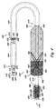
図1Aおよび1Bは、本開示によるシステム100の一実施形態を示す。様々な実施形態において、システム100は、長尺状送達カテーテル102、長尺状網目体104、弁106、およびフィルタ108を含む。図示するように、長尺状網目体104、弁106、およびフィルタ108はそれぞれ、長尺状送達カテーテル102の少なくとも一部分の周りに配置される。
1A and 1B illustrate one embodiment of a
様々な実施形態において、長尺状送達カテーテル102は、第1の長尺状本体110および第2の長尺状本体112を含む。第1の長尺状本体110は管腔114を含み、該管腔内を第2の長尺状本体112が長手方向に移動することができる。一実施形態では、第1および第2の長尺状本体110、112が、図示するように同心状に配置される。あるいは、長尺状本体110、112は、偏心配置されてもよい。
In various embodiments, the
カテーテル102の第1および第2の長尺状本体110、112はそれぞれ、基端116および先端118を含む。ガイドワイヤ管腔120が、第2の長尺状本体112の基端116と先端118との間を、その中を通って長手方向に延びる。ガイドワイヤ管腔120は、システム100の少なくとも一部を患者の体内の所望の位置に配置するために、ガイドワイヤを受容して、これを通過させることができる。
The first and second
様々な実施形態において、長尺状網目体104を、フィルタ108および弁106の先端側において、第2の長尺状本体112に取り付けることができる。一実施形態では、長尺状網目体104は、高強度材料によって形成されたワイヤの管状編組体122を含む。そのような材料の例としては、とりわけ、タンタル、ステンレス鋼合金(PERSS、304、316、17−7PH、17−4PH)、タングステン、モリブデン、MP35N、ElgiloyおよびL605などのコバルト合金、Nb−1Zr、白金、ロジウム、酸化イリジウム、ニチノール、タングステン、モリブデンおよびチタンなどの金属および金属合金が挙げられる。他の好適な高強度材料としては、とりわけ、ポリイミドおよびポリエーテルエーテルケトンなどの高強度ポリマー材料が挙げられる。
In various embodiments, the
様々な実施形態において、網目体104のフィラメントはモノフィラメント(すなわち、単一ストランド材料)とすることができる。あるいは、網目体104のフィラメントは、マルチストランド構成であってもよい。マルチストランド構成の例には、フィラメントの織り構成、編組み構成および/または撚り構成を含む。多層(例えば、同心)構成もまた可能である。これらの構成の組合せも可能である。
In various embodiments, the filaments of the
様々な実施形態において、ワイヤ122は断面形状および寸法の様々な組合せを有することができる。断面形状および/または寸法は、個々のワイヤ122に沿って異ならせてもよく、個々のワイヤ122および/またはワイヤ群122ごとに異ならせてもよい。断面形状および/または寸法は、例えば、網目体104の様々な展開段階において所望される径方向拡張力の生成に基づいて、選択することができる。
In various embodiments, the
好適な断面形状の例には、丸みを帯びた形状(例えば、円、楕円および/または長円)、直交する辺、1つまたは複数の凸状辺、または1つまたは複数の凹状辺を有する矩形;半円形;三角形;筒状;I字形;T字形;および台形を含むが、これらに限定されるものではない。断面形状および/または断面寸法は、ワイヤ122の各部分に要求される1つまたは複数の所望の機能に基づいて、同様にする、かつ/または、異ならせることができる。
Examples of suitable cross-sectional shapes have rounded shapes (eg, circles, ellipses and / or ellipses), orthogonal sides, one or more convex sides, or one or more concave sides Including, but not limited to: rectangular; semi-circular; triangular; cylindrical; I-shaped; T-shaped; The cross-sectional shape and / or cross-sectional dimensions can be similar and / or different based on one or more desired functions required for each portion of the
一実施形態では、長尺状網目体104が、第2の長尺状本体112の上を、先端118に隣接する第1の取付け位置124から先端118の基端側の第2の取付け位置126まで延びる。長尺状網目体104はまた、取付け位置124、126間において、長尺状送達カテーテル102の少なくとも一部分の周りに配置される拡張可能な領域128も含む。
In one embodiment, the
一実施形態では、システム100は、拡張可能な領域128の上に配置される人工弁129(断面図にて示す)も、さらに含むことができる。一実施形態では、拡張可能な領域128を使用して、人工弁129を上述のように段階的に展開することができ、拡張可能な領域128を使用して、拡張可能な領域128の灌流管腔136を通る血液灌流を維持しながら、人工弁129を非展開状態(図1Aに示す)から中間状態(図1Bに示す)へと動かすことができる。中間状態では、システム100を使用して、人工弁の位置を最終的な展開の前に調整することができるように、人工弁129を中間状態に保持することができる。
In one embodiment, the
引き戻し可能な部材130は、第2の長尺状本体112の管腔132を通って延び、第1および/または第2の取付け位置124、126の一方において、長尺状網目体104に固定される。一実施形態では、引き戻し可能な部材130は、カラー134の形態である第1の取付け位置124(すなわち、長尺状網目体104の先端部)において、長尺状網目体104に連結される。引き戻し可能な部材130に引っ張り力を加えることによって、カラー134が第2の長尺状本体112に沿って長手方向に摺動する。カラー134が摺動するにつれて、長尺状網目体104の拡張可能な領域128は、本明細書で説明するように、非展開状態から中間状態へと径方向に拡張する(すなわち、横断面が増大する)。引き戻し可能な部材130を使用してカラー134を摺動させ、拡張可能な領域128および人工弁129を完全に展開することもできる。
The
一実施形態では、引き戻し可能な部材130に加えられた引っ張り力が除去されると、長尺状網目体104は非拡張状態へと戻る。別の実施形態では、引き戻し可能な部材130に軸方向の力(すなわち、押す力)を加えて、長尺状網目体104が非拡張状態へ戻るように補助することができる。
In one embodiment, the
様々な実施形態において、弁106およびフィルタ108は、システム100の第1の長尺状本体110と結合されている。一実施形態では、フィルタ108は長尺状フィルタ本体140を含み、長尺状フィルタ本体140は、該フィルタ本体140の基端144から先端146へと延びる管腔142を画定する。一実施形態では、第2の長尺状本体112の一部分が、フィルタ本体140の管腔142を通過することができる。
In various embodiments, the
一実施形態では、弁106もまた管腔142の一部分を画定する。例えば、弁106を、長尺状フィルタ本体140の先端146の基端側に配置することができる。代替実施形態では、弁106を、長尺状フィルタ本体140の先端146の先端側に配置することができる。他の構成もまた可能である。
In one embodiment,
様々な実施形態において、弁106およびフィルタ104は、管腔142を通る流体の、流体の一方向流および濾過の両方を可能にする。弁106およびフィルタ104の寸法は、システム100が使用される体内管腔のタイプおよび体内管腔の寸法に基づいて選択することができる。
In various embodiments,
一方向流の提供に関して、弁106は、フレーム150および可逆的に密閉可能な開口154を提供する1つまたは複数の弁尖152を含む。可逆的に密閉可能な開口154の形成において、弁尖152は、開構成と閉構成との間で動くように構成されており、閉構成では弁尖152は、第2の長尺状本体112の一部分の周囲において、ならびに弁尖152の接合部で弁尖自体を、一時的に密閉することができる。
For providing unidirectional flow, the
様々な実施形態において、フレーム150は、弁106が置かれている体内管腔の内壁に対して適切な拡張力を加えることができる。さらに、フレーム150は、体内管腔の寸法(例えば、体内管腔の直径)の変化に対応して弾性的に拡張および収縮することによって体内管腔の寸法(例えば、体内管腔の直径)の変化に対応するように、可撓性を有する。フレーム150はまた、弁106の設置を促し、かつ、体内管腔内での逆流を防ぐために、体内管腔壁の表面に対して十分な接触および拡張力を提供する。
In various embodiments, the
フレーム150は、生体適合性金属、金属合金、ポリマー材料、またはそれらの組合せから形成することができ、これにより、本明細書で説明するように、フレーム150を収束状態と拡張状態との間で径方向に動かすことができる。これを達成するために、生体適合性金属、金属合金またはポリマー材料は、弾性変形から回復することができる高い弾性歪みのために低い弾性係数および高い降伏応力を示すものとすべきである。好適な材料の例には、医療用ステンレス鋼(例えば、316L)、チタン、タンタル、白金合金、ニオブ合金、コバルト合金、アルギン酸塩、またはそれらの組合せを含むが、これらに限定されるものではない。別の実施形態では、フレーム150を形状記憶材料から形成することができる。好適な形状記憶材料の例には、当業者にはニチノールとして知られている特定の比率のニッケルとチタンの合金を含むが、これに限定されるものではない。他の材料も可能である。
The
弁106は、1つまたは複数の放射線不透過性マーカー(例えば、タブ、スリーブ、溶接部)をさらに含むことができる。例えば、フレーム150の1つまたは複数の部分を、放射線不透過性材料から形成することができる。フレーム150に沿って1つまたは複数の位置に、放射線不透過性マーカーを取着および/または被覆することができる。放射線不透過性材料の例には、金、タンタルおよび白金を含むが、これらに限定されるものではない。1つまたは複数の放射線不透過性マーカーの位置は、植え込み中に、弁106の姿勢、位置および配向についての情報を提供するように選択することができる。
The
弁尖152は、合成材料または生体材料のいずれかであり得る、流体不透過性の生体適合性材料から製造することができる。可能な合成材料には、延伸ポリテトラフルオロエチレン(ePTFE)、ポリテトラフルオロエチレン(PTFE)、ポリスチレン−ポリイソブチレン−ポリスチレン、ポリウレタン、セグメント化ポリ(カーボネート−ウレタン)、ダクロン(登録商標)、ポリエチレン(PE)、ポリエチレンテレフタレート(PET)、サーリン(登録商標)、絹、ウレタン、レーヨン、シリコーン等を含むが、これらに限定されるものではない。別の好適な材料は、2007年2月5日に出願された米国仮特許出願第60/899,445号明細書、および「Synthetic Composite Structures」という名称の米国特許出願第 号(B&C整理番号204.0070001、BSCI整理番号07−000360US)に記載されており、これらの内容全体は、参照により本明細書の一部を構成する。可能な生体材料には、同種異系材料または異種移植片材料を含むが、これに限定されるものではない。これらは、小腸粘膜下組織(SIS)または臍帯静脈など、外植した静脈および脱細胞化した基底膜材料を含む。
The
弁尖152は、本明細書で説明する弁フレーム150の様々な実施形態に、任意の数の方法にて結合することができる。例えば、多様な締結具を使用して、弁尖152の材料を弁フレーム150に結合することができる。締結具には、生体適合性のステープル、接着剤、および縫合糸を含むことができるが、これらに限定されるものではない。一実施形態では、弁尖152の材料を、弁フレーム150の少なくとも一部の周りに巻き付け、締結具を使用して結合することができる。別の実施形態では、弁尖152を弁尖152の一部分(すなわち、弁尖自体)および/または弁フレーム150に、熱融着、溶剤接合、接着剤接合、または溶接することによって、弁尖152を弁フレーム150の様々な実施形態に結合することができる。弁尖152はまた、参照によりその内容全体が本明細書の一部を構成する、Sogardらの米国特許出願公開第2002/0178570号明細書に説明された方法に従って、弁フレーム150に取り付けることもできる。
The
弁104として使用するために好適な弁の例が、2003年12月19日に出願された、「Venous Valve Apparatus,System,and Method」という名称の米国特許出願第10/741,995号明細書(B&C整理番号201.0020001、BSCI整理番号03−340US)、および2005年2月7日に出願された、「Venous Valve Apparatus,System,and Method」という名称の米国特許出願第11/052,655号明細書(B&C整理番号201.0120001、BSCI整理番号04−0080US)に説明されており、ともに、参照によりその内容全体が本明細書の一部を構成する。
An example of a valve suitable for use as
様々な実施形態において、長尺状フィルタ本体140は弁106を通って移動する血液の一方向流を濾過する。本明細書で述べる「濾過」には、弁106を通って移動する血液内に放出された、および/または存在する、特定の物質の通過の捕捉および/または阻止を含むことができる。次いで、捕捉された粒子物質を、システム100を使用して除去することができる。
In various embodiments, the
図1A〜1Bに示すように、弁106を、長尺状フィルタ本体140の先端146の基端側に接続することができる。例えば、弁106のフレーム150を、長尺状フィルタ本体140の先端146の基端側において長尺状フィルタ本体140に結合することができる。フレーム150を長尺状フィルタ本体140に結合する方法は、弁尖152をフレーム150に結合するために本明細書で説明した通りとすることができる。
1A-1B, the
一実施形態では、長尺状フィルタ本体140は、第1の構成(例えば、圧縮状態)と第2の構成(例えば、拡張状態。図1A〜1Bを参照)との間で動く。一実施形態では、長尺状フィルタ本体140は、フレーム150が拡張するにつれてフレーム150によって加えられる力によって、第1の構成から第2の構成へと拡張することができる。さらに、長尺状フィルタ本体140は、フレーム150が拡張するにつれてフレーム150によって加えられる力と流体の一方向流の圧力下で加えられる力の組合せによって、第1の構成から第2の構成へと拡張することができる。さらに、弁が開構成にあるときにフレームによって加えられる力は、例えば弁が閉構成にあるときなど、逆行する流体が流れるときに、拡張可能なフィルタ領域を拡張状態に維持することを助けることができる。別の実施形態では、長尺状フィルタ本体140を、圧縮状態から解除されると径方向に自己拡張するように構成することができる。
In one embodiment, the
様々な実施形態において、展開状態にある長尺状フィルタ本体140は、フィルタ108および弁104が展開される管腔の断面積を満たすことができる。さらに、展開状態にある長尺状フィルタ本体140は、フィルタ本体140と管腔壁面との間を通過し得る流体(例えば、血液)の量を低減するように、十分な圧力を管腔の内壁に加えることができる。一実施形態では、弁フレーム150は、少なくともその一部が体内管腔の内壁に十分な圧力を加えるように使用することができる。展開状態にある長尺状フィルタ本体140によって画定される面積および形状(例えば、拡張可能なフィルタ領域の直径)は、装置の使用が意図される場所に左右され得ることが理解されよう。
In various embodiments, the
長尺状フィルタ本体140の例には、織り構成、編組み構成および/または編み構成を含み、これらは当業者には既知であり理解されよう。あるいは、長尺状フィルタ本体140は、細孔が形成された、または細孔をあけた材料から形成することができる。様々な実施形態において、長尺状フィルタ本体140は、多くの材料から形成することができる。材料には、ePTFE、PTFE、ポリスチレン−ポリイソブチレン−ポリスチレン、ポリウレタン、セグメント化ポリ(カーボネート−ウレタン)、ダクロン(登録商標)、PE、PET、絹、ウレタン、レーヨン、シリコーン、ポリアミドなどのポリマー、それらの混合物およびブロックコポリマーを含むことができる。
Examples of
一実施形態では、拡張可能な長尺状フィルタ本体140は、有害になり得る塞栓が、脳、心臓、腎臓、ならびに他の組織および器官に血液を供給する動脈へと通り抜けることを減らすように、構成することができる。例えば、長尺状フィルタ本体140は、断面寸法が約5〜1000マイクロメートルより大きな塞栓の通過を減らし、または防ぐ助けとなり得る。拡張可能な長尺状フィルタ本体140はまた、断面寸法が50〜200マイクロメートルより大きな塞栓の通過も防ぐことができる。より効率的に塞栓を濾過するために、より大きな粒子を捕捉する長尺状フィルタ本体140の200マイクロメートル部分、およびより小さな粒子を捕捉する長尺状フィルタ本体140の75マイクロメートル部分など、長尺状フィルタ本体140の複数の領域または層を組み込むことができる。
In one embodiment, the expandable
長尺状フィルタ本体140の別の例には、指定の温度または温度範囲で形状が変化する感温性の記憶合金から形成された、径方向自己拡張構成を含む。そのような材料の例には、ニチノールおよびニチノールタイプの金属合金を含むが、これらに限定されるものではない。あるいは、長尺状フィルタ本体140の自己拡張構成には、長尺状フィルタ本体140を形成する部材がばねで付勢されているものを含む。長尺状フィルタ本体140は、長尺状フィルタ本体140を自己拡張させることもできる、織り構成、編組み構成および/または編み構成を有することができる。
Another example of the
別の実施形態では、長尺状フィルタ本体140は放射線不透過性マーカーをさらに含むことができる。例えば、(例えば、取着または被覆した)放射線不透過性マーカーを使用して、弁106および/または長尺状フィルタ本体140の位置を明らかにすることができる。必要に応じて、システム100の部品の位置および姿勢を視覚化できるようにするために、システム100の他の部分を放射線不透過性マーカーでマークすることもできる。
In another embodiment, the
様々な実施形態において、システム100は、管腔158を有するシース156をさらに含むことができ、非展開状態の弁106およびフィルタ108を保持するように、システム100の少なくとも一部分を管腔158内に収容することができる。弁106およびフィルタ108の周りからシース156を引き戻すことによって、弁106およびフィルタ108を展開することができる。
In various embodiments, the
シース156は、多くの材料から形成することができる。材料には、PVC、PE、POC、PET、ポリアミドなどのポリマー、それらの混合物、およびブロックコポリマーを含む。さらに、シース156は、弁106およびフィルタ108の両方が管腔158内に配置されているときに、これらを引き戻された状態に維持するために十分な壁厚および内径を有することができる。
The
図2は、本開示によるシステム200の別の実施形態を示す。様々な実施形態において、システム200は、本明細書で説明するように、長尺状送達カテーテル202、長尺状網目体204、弁206、およびフィルタ208を含む。
FIG. 2 illustrates another embodiment of a
さらに、システム200は、長尺状送達カテーテル202の第2の長尺状本体212の基端216から膨張バルーン260の内部へと延びる膨張管腔262に接続された、膨張可能なバルーン260をさらに含む。本実施形態では、膨張可能なバルーン260は、長尺状送達カテーテル202の第2の長尺状本体212の少なくとも一部分の周りにおいて、長尺状送達カテーテルと長尺状網目体との間に配置される。
Additionally, the
様々な実施形態において、バルーン260は、人工弁229を送達状態(例えば、非展開状態)から中間状態へと拡張するように膨張させることができる。次いで、バルーン260が収縮させられ、引き戻し可能な部材230が長尺状網目体204の基端244に向かって先端246を移動させると、拡張可能な領域228が中間状態から展開状態へと拡張することができる。一実施形態では、このように弁229を展開することによって、弁229を中間状態(例えば、部分的に展開されたバルーンの周りを血液が流れる)、および最終展開状態(例えば、長尺状網目体208の管腔を通って血液が流れる)へと拡張しながら、血液を灌流させることが可能になる。
In various embodiments, the
別の実施形態では、バルーン260によって弁229を初期拡張させることによって、長尺状網目体208が大きな初期径方向拡張力を生成する必要がないようにしている。さらに、長尺状網目体208の径方向拡張を中間状態から開始することによって、弁229を展開状態へと拡張するために十分な径方向拡張力を生成する、有利な開始位置が提供される。
In another embodiment, the
図3は、本開示によるシステム300の別の実施形態を示す。様々な実施形態において、システム300は、本明細書で説明するように、長尺状送達カテーテル302、長尺状網目体304、弁306、およびフィルタ308を含む。
FIG. 3 illustrates another embodiment of a
さらに、システム300は、長尺状送達カテーテル302の第2の長尺状本体312の基端316から膨張バルーン360の内部へと延びる膨張管腔362に接続された、膨張可能なバルーン360をさらに含む。本実施形態では、膨張可能なバルーン360は、長尺状送達カテーテル302の第2の長尺状本体312の少なくとも一部分の周りにおいて、長尺状送達カテーテル302の第2の長尺状本体312と長尺状網目体304との間に配置される。
Further, the
様々な実施形態において、網目体304の拡張可能な領域328および人工弁329を、送達状態(例えば、非展開状態)から中間状態へと拡張するために、バルーン360は第1の拡張状態へと膨張することができる。次いで、バルーン360を第2の拡張状態へと収縮させ、引き戻し可能な部材330が長尺状網目体304の基端344に向かって先端346を移動させると、拡張可能な領域328を中間状態から展開状態へと拡張させることができる。一実施形態では、バルーン360を第1の拡張状態より大きな第3の拡張状態へと膨張させて、弁329を設置することができる。
In various embodiments, in order to expand the
一実施形態では、このように弁329を展開することによって、弁329を中間状態(例えば、部分的に展開されたバルーンの周りを血液が流れる)、および最終展開状態(例えば、網目体304の管腔を通って血液が流れる)へと拡張させながら、血液を灌流させることが可能になる。別の実施形態では、バルーン360によって弁329および網目体304を初期拡張させることによって、網目体304が大きな初期径方向拡張力を生成する必要がないようにしている。さらに、長尺状網目体304の径方向拡張を中間状態から開始することによって、弁329を展開状態へと拡張するために十分な径方向拡張力を生成する、有利な開始位置が提供される。
In one embodiment, by deploying
図4は、本開示によるシステム400の別の実施形態を示す。様々な実施形態において、システム400は、本明細書で説明するように、長尺状送達カテーテル402、長尺状網目体404、弁406、およびフィルタ408を含む。
FIG. 4 illustrates another embodiment of a
さらに、システム400は、第2の長尺状本体412の少なくとも一部分の周りにおいて、長尺状送達カテーテル402と長尺状網目体404との間に配置される第2の長尺状網目体466をさらに含む。第2の長尺状本体412は、第2の長尺状本体112の管腔470を通って延び、かつ、第1および/または第2の取付け位置472、474の一方において第2の長尺状網目体466に固定された、第2の引き戻し可能な部材468をさらに含む。一実施形態では、引き戻し可能な部材468は、カラー476の形態である第1の取付け位置472(すなわち、第2の長尺状網目体466の先端部)において、第2の長尺状網目体466に連結される。
Further, the
一実施形態では、引き戻し可能な部材468に引っ張り力を加えることによって、カラー476は第2の長尺状本体412に沿って長手方向に摺動する。カラー476が摺動するにつれて、第2の長尺状網目体466が拡張して、長尺状網目体404の拡張可能な領域428を送達状態から中間状態へと移行させる。次いで、引き戻し可能な部材430に引っ張り力を加えて、網目体404の拡張可能な領域428を中間状態から展開状態へと拡張することができる。
In one embodiment, the
一実施形態では、長尺状網目体404および第2の長尺状網目体466はそれぞれ、異なる目的を果たすために、異なる織り構成および/または異なるワイヤ422構成を有することができる。例えば、第2の長尺状網目体466の構成(例えば、織りおよび/またはワイヤ構成)は、弁429を非展開状態から中間状態に向かって初期径方向拡張させるように作製することができ、長尺状網目体404の構成は、弁429が中間状態から展開状態へと径方向に拡張するために十分な程度まで径方向拡張を継続するように作製することができる。
In one embodiment, the
本開示の実施形態はさらに、本明細書で説明するシステムを形成するための方法を含む。例えば、本開示の実施形態は、第1の長尺状本体および第2の長尺状本体を有する長尺状送達カテーテルを設けることによって形成することができ、第1の長尺状本体は、第2の長尺状本体が中を通って長手方向に移動することができる管腔を含む。 Embodiments of the present disclosure further include a method for forming the system described herein. For example, embodiments of the present disclosure can be formed by providing an elongate delivery catheter having a first elongate body and a second elongate body, the first elongate body comprising: A second elongate body includes a lumen through which it can move longitudinally.
弁構造は、本明細書で説明するように、フィルタの長尺状フィルタ本体に結合されて通路を形成し、該通路内を通って流体が流れることができ、長尺状フィルタ本体によって該流体を濾過することができる。拡張可能な領域を有する長尺状網目体も、長尺状送達カテーテルの少なくとも一部分の周りにおいて、長尺状フィルタ本体および弁構造の先端側に配置される。人工弁は、長尺状網目体の拡張可能な領域の上に配置されており、拡張可能な領域は、本明細書で説明するように、人工弁の少なくとも一部を展開するように、径方向に拡張することができる。一実施形態では、長尺状網目体の先端が、本明細書で説明するように、長尺状網目体の拡張可能な領域を径方向に拡張するように長手方向に移動することができる。 The valve structure is coupled to the elongate filter body of the filter to form a passage through which the fluid can flow, as described herein, by the elongate filter body. Can be filtered. An elongate mesh having an expandable region is also disposed on the distal side of the elongate filter body and valve structure around at least a portion of the elongate delivery catheter. The prosthetic valve is disposed over the expandable region of the elongated mesh, and the expandable region is configured to deploy at least a portion of the prosthetic valve as described herein. Can be expanded in the direction. In one embodiment, the tip of the elongated mesh can be moved longitudinally to radially expand the expandable region of the elongated mesh as described herein.
システムの実施形態はまた、本明細書で説明する膨張可能なバルーンを含むことができる。これらの実施形態では、長尺状送達カテーテルが、長尺状送達カテーテルを通って延びる管腔を、膨張可能なバルーンと液密に連通するように備えている。上述したように、膨張可能なバルーンは、長尺状送達カテーテルと長尺状網目体との間に配置することができる。あるいは、長尺状網目体は、長尺状送達カテーテルと膨張可能なバルーンとの間に配置してもよい。 System embodiments can also include an inflatable balloon as described herein. In these embodiments, the elongate delivery catheter includes a lumen extending through the elongate delivery catheter so as to be in fluid tight communication with the inflatable balloon. As described above, the inflatable balloon can be placed between the elongated delivery catheter and the elongated mesh. Alternatively, the elongated mesh may be placed between the elongated delivery catheter and the inflatable balloon.
本開示の実施形態はまた、長尺状送達カテーテルと長尺状網目体との間に配置された第2の長尺状網目体も含むことができ、第2の長尺状網目体は、本明細書で説明するように、長尺状網目体および人工弁の少なくとも一部を展開するように拡張する。 Embodiments of the present disclosure can also include a second elongated mesh disposed between the elongated delivery catheter and the elongated mesh, wherein the second elongated mesh is As described herein, at least a portion of the elongated mesh and the prosthetic valve are expanded to deploy.
別の実施形態では、人工弁は、人工弁フレームの外周に配置された膨張可能な密閉材料をさらに含むことができる。一実施形態では、密閉材料は、組織に植え込まれた後、人工弁外側の周りに液体が漏れないようにするために、弁フレームと弁が植え込まれた組織との間の容積を占めるように、液体によって膨らむことができる。 In another embodiment, the prosthetic valve can further include an inflatable sealing material disposed on the outer periphery of the prosthetic valve frame. In one embodiment, the sealing material occupies a volume between the valve frame and the tissue in which the valve is implanted in order to prevent liquid from leaking around the outside of the prosthetic valve after being implanted in the tissue. As such, it can be inflated with liquid.
好適な密閉材料には、多様な材料が可能である。例えば、密閉材料は、ポリサッカリド、タンパク質、および生体適合性ゲルを含む一般的なクラスの材料から選択することができる。これらのポリマー材料の特定の例には、ポリ(エチレンオキシド)(PEO)、PET、ポリ(エチレングリコール)(PEG)、ポリ(ビニルアルコール)(PVA)、ポリ(ビニルピロリドン)(PVP)、ポリ(エチルオキサゾリン)(PEOX)ポリアミノ酸、擬似ポリアミノ酸、およびポリエチルオキサゾリンから誘導されるもの、ならびにこれらの互いとのコポリマーあるいは他の水溶性ポリマーまたは水不溶性ポリマーとのコポリマーを含むが、これらに限定されるものではない。ポリサッカリドの例には、アルギン酸塩、ヒアルロン酸、コンドロイチン硫酸、デキストラン、デキストラン硫酸、ヘパリン、ヘパリン硫酸、ヘパラン硫酸、キトサン、ゲランガム、キサンタンガム、グアーガム、水溶性セルロース誘導体、およびカラギーナンから誘導されるものを含む。タンパク質の例には、天然または遺伝子組換え源のいずれから製造されるかにかかわりなく、ゼラチン、コラーゲン、エラスチン、ゼイン、およびアルブミンから誘導されるものを含む。 A variety of materials are possible as suitable sealing materials. For example, the sealing material can be selected from the general class of materials including polysaccharides, proteins, and biocompatible gels. Specific examples of these polymeric materials include poly (ethylene oxide) (PEO), PET, poly (ethylene glycol) (PEG), poly (vinyl alcohol) (PVA), poly (vinyl pyrrolidone) (PVP), poly ( Ethyloxazoline) (PEOX) polyamino acids, pseudopolyamino acids, and those derived from polyethyloxazoline, and copolymers thereof with one another or with other water-soluble or water-insoluble polymers. Is not to be done. Examples of polysaccharides include those derived from alginate, hyaluronic acid, chondroitin sulfate, dextran, dextran sulfate, heparin, heparin sulfate, heparan sulfate, chitosan, gellan gum, xanthan gum, guar gum, water-soluble cellulose derivatives, and carrageenan. Including. Examples of proteins include those derived from gelatin, collagen, elastin, zein, and albumin, whether produced from natural or genetically modified sources.
本明細書で説明する弁の実施形態を使用して、1つまたは複数の体内管腔で弁構造を置換、補完、または補強することができる。例えば、本発明の実施形態を使用して、大動脈弁、肺動脈弁、および/または僧帽弁などの、機能不全の心臓弁を置換することができる。一実施形態では、患者本来の心臓弁をそのまま残すこともでき、または本開示の弁を植え込む前に(例えば、弁形成術によって)除去することもできる。 The valve embodiments described herein can be used to replace, supplement, or reinforce a valve structure with one or more body lumens. For example, embodiments of the invention can be used to replace dysfunctional heart valves, such as aortic valves, pulmonary valves, and / or mitral valves. In one embodiment, the patient's native heart valve can be left intact or can be removed (eg, by valvuloplasty) prior to implantation of the valve of the present disclosure.
さらに、本明細書で説明する弁を含むシステムを配置することには、該システムを、侵襲性が最小限の経皮経管的な手技を使用して患者の心血管系へと導入することが含まれる。例えば、ガイドワイヤを、あらかじめ定めた場所を含む患者の心血管系内に配置することができる。本明細書で説明する弁を含む本開示のシステムをガイドワイヤ上に配置し、あらかじめ定めた場所にまたはそれに隣接して弁を配置するように該システムを前進させることができる。一実施形態では、本明細書で説明するカテーテルおよび/または弁の放射線不透過性マーカーを使用して、弁の位置を特定して配置する助けとすることができる。 In addition, deploying a system that includes a valve as described herein introduces the system into the patient's cardiovascular system using a minimally invasive percutaneous transluminal procedure. Is included. For example, a guidewire can be placed in the patient's cardiovascular system including a predetermined location. The system of the present disclosure, including the valves described herein, can be placed on a guide wire and advanced to place the valve at or adjacent to a predetermined location. In one embodiment, the radiopaque markers of the catheter and / or valve described herein can be used to help locate and position the valve.
弁は、本明細書で説明するように、任意の数の方法によって、あらかじめ定めた場所においてシステムから展開することができる。一実施形態では、本開示の弁を、心血管系の任意の数の場所で展開して留置することができる。例えば、弁を患者の主幹動脈内に展開して留置することができる。一実施形態では、主幹動脈には大動脈を含むが、これに限定されるものではない。さらに、例えば肺動脈弁を置換および/または補強するために肺動脈に、あるいは、僧帽弁を置換および/または補強するために左心房と左心室の間になど、本発明の弁を心臓の他の主幹動脈内および/または心臓そのものの内部に展開して留置することができる。他の場所も可能である。 The valve can be deployed from the system at a predetermined location in any number of ways, as described herein. In one embodiment, the valve of the present disclosure can be deployed and deployed in any number of locations in the cardiovascular system. For example, a valve can be deployed and placed in the patient's main artery. In one embodiment, the main artery includes, but is not limited to, the aorta. In addition, the valve of the present invention can be applied to other parts of the heart, such as to the pulmonary artery to replace and / or reinforce the pulmonary valve, or between the left atrium and left ventricle to replace and / or reinforce the mitral valve It can be deployed and placed in the main trunk artery and / or within the heart itself. Other locations are possible.
本開示について図示し、詳しく説明してきたが、当業者であれば、本開示の主旨及び範囲を逸脱することなく、変更および改変を加えることができることは明らかであろう。したがって、上記の説明および添付の図面に記載された内容は、例示のためだけに提供されたものであって、本発明を限定するためのものではない。本開示の実際の範囲は、添付の特許請求の範囲、ならびにこれらの請求項による権利範囲のすべての均等物によって定義されるものとする。 Although the present disclosure has been shown and described in detail, it will be apparent to those skilled in the art that changes and modifications can be made without departing from the spirit and scope of the disclosure. Accordingly, what has been described in the above description and accompanying drawings is provided by way of illustration only and not as a limitation of the present invention. The actual scope of the disclosure is to be defined by the appended claims, as well as all equivalents of the scope of the claims.
さらに、当業者であれば、本開示を読解すれば、本明細書で説明した発明についての他の変形形態も本開示の範囲内に包含され得ることが理解されよう。例えば、支持フレーム120および/またはカバー122を、現在知られているまたは将来知られるであろう非血栓形成性の生体適合性材料で被覆することができる。
Further, those of ordinary skill in the art will understand from reading this disclosure that other variations on the invention described herein may be included within the scope of this disclosure. For example, the
上記詳細な説明においては、開示を円滑に行うために、様々な特徴が、いくつかの実施形態に分類されている。この開示方法は、本開示の実施形態が、各請求項で明示的に述べられているよりも多くの特徴を必要とすることを反映していると解釈するべきではない。むしろ、添付の請求項が反映しているように、本開示の主題は、1つの開示された実施形態のすべての特徴よりも少ないものである。したがって、添付の特許請求の範囲は、各請求項が別個の実施形態として自立的なものとして、詳細な説明に組み込まれるものである。 In the foregoing detailed description, various features are grouped into several embodiments to facilitate disclosure. This method of disclosure is not to be interpreted as reflecting that the embodiments of the present disclosure require more features than are expressly recited in each claim. Rather, as the appended claims reflect, the subject matter of this disclosure is less than all the features of one disclosed embodiment. Thus, the following claims are hereby incorporated into the Detailed Description, with each claim standing on its own as a separate embodiment.
Claims (3)
前記長尺状送達カテーテル(102、202、302、402)の少なくとも一部分の周りに配置される拡張可能な領域(128、228、328、428)を含む長尺状網目体(104、204、304、404)と、
前記長尺状送達カテーテル(102、202、302、402)を通って延びる第2の長尺状本体(112、212、312、412)と、
同第2の長尺状本体(112、212、312、412)の少なくとも一部分の周りに配置されるカラー(134、234、334)と、
前記長尺状送達カテーテル(102、202、302、402)を通って延びて、前記カラー(134、234、334)に連結される引き戻し可能な部材(130、230、330、430)であって、該長尺状網目体(104、204、304、404)の拡張可能な領域(128、228、328、428)を非展開状態から中間状態へと径方向に拡張させるように前記カラー(134、234、334)が第2の長尺状本体(112、212、312、412)に沿って長手方向に摺動する、引き戻し可能な部材(130、230、330、430)と、
前記長尺状送達カテーテル(102、202、302、402)位置の少なくとも一部分の周りに配置される弁(106、206、306、406)と、
前記長尺状送達カテーテル(102、202、302、402)の少なくとも一部分の周りに配置されるフィルタ(108、208、308、408)と、
前記長尺状送達カテーテル(102、202、302、402)の少なくとも一部分の周りにおいて、該長尺状送達カテーテル(102、202、302、402)と前記長尺状網目体(104、204、304、404)との間に配置される第2の長尺状網目体(466)とを含むシステム(100、200、300、400)。 An elongate delivery catheter (102, 202, 302, 402);
An elongate mesh (104, 204, 304) that includes an expandable region (128, 228, 328, 428) disposed around at least a portion of the elongate delivery catheter (102, 202, 302, 402). 404)
A second elongate body (112, 212, 312, 412) extending through the elongate delivery catheter (102, 202, 302, 402);
A collar (134, 234, 334) disposed around at least a portion of the second elongate body (112, 212, 312, 412);
A retractable member (130, 230, 330, 430) extending through the elongate delivery catheter (102, 202, 302, 402) and coupled to the collar (134, 234, 334); The collar (134) to radially expand the expandable region (128, 228, 328, 428) of the elongated mesh (104, 204, 304, 404) from a non-deployed state to an intermediate state. 234, 334) sliding longitudinally along the second elongate body (112, 212, 312, 412), and retractable members (130, 230, 330, 430);
A valve (106, 206, 306, 406) disposed about at least a portion of the elongate delivery catheter (102, 202, 302, 402) position;
A filter (108, 208, 308, 408) disposed around at least a portion of the elongate delivery catheter (102, 202, 302, 402);
Around at least a portion of the elongate delivery catheter (102, 202, 302, 402), the elongate delivery catheter (102, 202, 302, 402) and the elongate mesh (104, 204, 304). , 404) and a second elongated mesh (466) disposed between (100, 200, 300, 400).
Applications Claiming Priority (3)
| Application Number | Priority Date | Filing Date | Title |
|---|---|---|---|
| US89948807P | 2007-02-05 | 2007-02-05 | |
| US60/899,488 | 2007-02-05 | ||
| PCT/US2008/001537 WO2008097556A1 (en) | 2007-02-05 | 2008-02-05 | Systems and methods for valve delivery |
Publications (2)
| Publication Number | Publication Date |
|---|---|
| JP2010517622A JP2010517622A (en) | 2010-05-27 |
| JP5604110B2 true JP5604110B2 (en) | 2014-10-08 |
Family
ID=39469340
Family Applications (1)
| Application Number | Title | Priority Date | Filing Date |
|---|---|---|---|
| JP2009548338A Expired - Fee Related JP5604110B2 (en) | 2007-02-05 | 2008-02-05 | System for delivering a valve |
Country Status (4)
| Country | Link |
|---|---|
| US (1) | US20080269877A1 (en) |
| EP (1) | EP2117468A1 (en) |
| JP (1) | JP5604110B2 (en) |
| WO (1) | WO2008097556A1 (en) |
Families Citing this family (28)
| Publication number | Priority date | Publication date | Assignee | Title |
|---|---|---|---|---|
| US7566343B2 (en) | 2004-09-02 | 2009-07-28 | Boston Scientific Scimed, Inc. | Cardiac valve, system, and method |
| US20060173490A1 (en) * | 2005-02-01 | 2006-08-03 | Boston Scientific Scimed, Inc. | Filter system and method |
| US8663319B2 (en) | 2007-07-23 | 2014-03-04 | Hocor Cardiovascular Technologies Llc | Methods and apparatus for percutaneous aortic valve replacement |
| US8663318B2 (en) * | 2007-07-23 | 2014-03-04 | Hocor Cardiovascular Technologies Llc | Method and apparatus for percutaneous aortic valve replacement |
| US8137398B2 (en) * | 2008-10-13 | 2012-03-20 | Medtronic Ventor Technologies Ltd | Prosthetic valve having tapered tip when compressed for delivery |
| EP2533730A1 (en) * | 2010-02-10 | 2012-12-19 | Apertomed, L.L.C. | Methods, systems and devices for treatment of cerebrospinal venous insufficiency and multiple sclerosis |
| US9119717B2 (en) | 2010-07-15 | 2015-09-01 | St. Jude Medical, Inc. | Retainers for transcatheter heart valve delivery systems |
| WO2012012660A2 (en) * | 2010-07-21 | 2012-01-26 | Accola Kevin D | Prosthetic heart valves and devices, systems, and methods for deploying prosthetic heart valves |
| WO2012015825A2 (en) | 2010-07-27 | 2012-02-02 | Incept, Llc | Methods and apparatus for treating neurovascular venous outflow obstruction |
| US10130470B2 (en) | 2010-08-17 | 2018-11-20 | St. Jude Medical, Llc | Sleeve for facilitating movement of a transfemoral catheter |
| AU2011302639B2 (en) | 2010-09-17 | 2014-07-31 | St. Jude Medical, Cardiology Division, Inc. | Retainers for transcatheter heart valve delivery systems |
| EP2522307B1 (en) * | 2011-05-08 | 2020-09-30 | ITSO Medical AB | Device for delivery of medical devices to a cardiac valve |
| EP2736450A1 (en) | 2011-07-28 | 2014-06-04 | St. Jude Medical, Inc. | Expandable radiopaque marker for transcatheter aortic valve implantation |
| WO2013059603A1 (en) * | 2011-10-19 | 2013-04-25 | Don Michael T Anthony | Apparatus and procedure for trapping embolic debris |
| US9480561B2 (en) | 2012-06-26 | 2016-11-01 | St. Jude Medical, Cardiology Division, Inc. | Apparatus and method for aortic protection and TAVI planar alignment |
| US9918837B2 (en) | 2012-06-29 | 2018-03-20 | St. Jude Medical, Cardiology Division, Inc. | System to assist in the release of a collapsible stent from a delivery device |
| WO2015065910A2 (en) * | 2013-10-30 | 2015-05-07 | The Regents Of The University Of Michigan | System and method to limit cerebral ischemia |
| CN113576714A (en) * | 2015-02-02 | 2021-11-02 | 赛姆斯股份公司 | Stent seal and method of making same |
| US20170007397A1 (en) * | 2015-07-09 | 2017-01-12 | David Rizik | Method and apparatus for practice of tavr employing an expandable mesh-like catheter |
| US10500046B2 (en) | 2015-12-14 | 2019-12-10 | Medtronic, Inc. | Delivery system having retractable wires as a coupling mechanism and a deployment mechanism for a self-expanding prosthesis |
| US10159568B2 (en) | 2015-12-14 | 2018-12-25 | Medtronic, Inc. | Delivery system having retractable wires as a coupling mechanism and a deployment mechanism for a self-expanding prosthesis |
| EP3454794B1 (en) | 2016-05-13 | 2021-04-14 | St. Jude Medical, Cardiology Division, Inc. | Systems for device implantation |
| US10653523B2 (en) | 2017-01-19 | 2020-05-19 | 4C Medical Technologies, Inc. | Systems, methods and devices for delivery systems, methods and devices for implanting prosthetic heart valves |
| US10561495B2 (en) | 2017-01-24 | 2020-02-18 | 4C Medical Technologies, Inc. | Systems, methods and devices for two-step delivery and implantation of prosthetic heart valve |
| EP3403615A1 (en) * | 2017-05-17 | 2018-11-21 | Aorticlab Sarl | Transcatheter valve prosthesis for blood vessel |
| US11857441B2 (en) | 2018-09-04 | 2024-01-02 | 4C Medical Technologies, Inc. | Stent loading device |
| US11931253B2 (en) | 2020-01-31 | 2024-03-19 | 4C Medical Technologies, Inc. | Prosthetic heart valve delivery system: ball-slide attachment |
| CN112402060A (en) * | 2020-11-02 | 2021-02-26 | 金仕生物科技(常熟)有限公司 | Delivery system of intervention valve |
Family Cites Families (91)
| Publication number | Priority date | Publication date | Assignee | Title |
|---|---|---|---|---|
| US3996938A (en) * | 1975-07-10 | 1976-12-14 | Clark Iii William T | Expanding mesh catheter |
| US4994077A (en) * | 1989-04-21 | 1991-02-19 | Dobben Richard L | Artificial heart valve for implantation in a blood vessel |
| US6010531A (en) * | 1993-02-22 | 2000-01-04 | Heartport, Inc. | Less-invasive devices and methods for cardiac valve surgery |
| US5713950A (en) * | 1993-11-01 | 1998-02-03 | Cox; James L. | Method of replacing heart valves using flexible tubes |
| WO1996004028A1 (en) * | 1994-07-29 | 1996-02-15 | Baxter International Inc. | Methods for treating implantable biological tissues to mitigate the calcification thereof and bioprosthetic articles treated by such methods |
| US5716370A (en) * | 1996-02-23 | 1998-02-10 | Williamson, Iv; Warren | Means for replacing a heart valve in a minimally invasive manner |
| CN1568905B (en) * | 1996-06-20 | 2010-04-28 | 瓦斯卡泰克有限公司 | Prosthesis reparation of body conduit |
| NL1004827C2 (en) * | 1996-12-18 | 1998-06-19 | Surgical Innovations Vof | Device for regulating blood circulation. |
| US5928281A (en) * | 1997-03-27 | 1999-07-27 | Baxter International Inc. | Tissue heart valves |
| US5961549A (en) * | 1997-04-03 | 1999-10-05 | Baxter International Inc. | Multi-leaflet bioprosthetic heart valve |
| US5911734A (en) * | 1997-05-08 | 1999-06-15 | Embol-X, Inc. | Percutaneous catheter and guidewire having filter and medical device deployment capabilities |
| CA2264561C (en) * | 1997-06-27 | 2013-04-09 | The Trustees Of Columbia University In The City Of New York | Method and apparatus for circulatory valve repair |
| AU754156B2 (en) * | 1998-06-02 | 2002-11-07 | Cook Incorporated | Multiple-sided intraluminal medical device |
| US6165183A (en) * | 1998-07-15 | 2000-12-26 | St. Jude Medical, Inc. | Mitral and tricuspid valve repair |
| US6051014A (en) * | 1998-10-13 | 2000-04-18 | Embol-X, Inc. | Percutaneous filtration catheter for valve repair surgery and methods of use |
| JP2002537761A (en) * | 1998-11-24 | 2002-11-12 | リージェンツ オブ ザ ユニバーシティ オブ ミネソタ | Transgenic circulating endothelial cells |
| WO2000042951A1 (en) * | 1999-01-26 | 2000-07-27 | Edwards Lifesciences Corporation | Anatomical orifice sizers and methods of orifice sizing |
| US6896690B1 (en) * | 2000-01-27 | 2005-05-24 | Viacor, Inc. | Cardiac valve procedure methods and devices |
| US6752813B2 (en) * | 1999-04-09 | 2004-06-22 | Evalve, Inc. | Methods and devices for capturing and fixing leaflets in valve repair |
| ATE492219T1 (en) * | 1999-04-09 | 2011-01-15 | Evalve Inc | DEVICE FOR HEART VALVE OPERATION |
| SE514718C2 (en) * | 1999-06-29 | 2001-04-09 | Jan Otto Solem | Apparatus for treating defective closure of the mitral valve apparatus |
| US6997951B2 (en) * | 1999-06-30 | 2006-02-14 | Edwards Lifesciences Ag | Method and device for treatment of mitral insufficiency |
| US6312447B1 (en) * | 1999-10-13 | 2001-11-06 | The General Hospital Corporation | Devices and methods for percutaneous mitral valve repair |
| US6440164B1 (en) * | 1999-10-21 | 2002-08-27 | Scimed Life Systems, Inc. | Implantable prosthetic valve |
| WO2001055473A1 (en) * | 2000-01-25 | 2001-08-02 | Boston Scientific Limited | Manufacturing medical devices by vapor deposition |
| HUP0204398A2 (en) * | 2000-01-27 | 2003-03-28 | 3F Therapeutics | Prosthetic heart valve |
| US7749245B2 (en) * | 2000-01-27 | 2010-07-06 | Medtronic, Inc. | Cardiac valve procedure methods and devices |
| US6692513B2 (en) * | 2000-06-30 | 2004-02-17 | Viacor, Inc. | Intravascular filter with debris entrapment mechanism |
| US6989028B2 (en) * | 2000-01-31 | 2006-01-24 | Edwards Lifesciences Ag | Medical system and method for remodeling an extravascular tissue structure |
| CA2407439C (en) * | 2000-04-27 | 2008-07-08 | Axel Haverich | Individual venous valve prosthesis |
| US6840246B2 (en) * | 2000-06-20 | 2005-01-11 | University Of Maryland, Baltimore | Apparatuses and methods for performing minimally invasive diagnostic and surgical procedures inside of a beating heart |
| US6695878B2 (en) * | 2000-06-26 | 2004-02-24 | Rex Medical, L.P. | Vascular device for valve leaflet apposition |
| US6676698B2 (en) * | 2000-06-26 | 2004-01-13 | Rex Medicol, L.P. | Vascular device with valve for approximating vessel wall |
| US6695817B1 (en) * | 2000-07-11 | 2004-02-24 | Icu Medical, Inc. | Medical valve with positive flow characteristics |
| US6846325B2 (en) * | 2000-09-07 | 2005-01-25 | Viacor, Inc. | Fixation band for affixing a prosthetic heart valve to tissue |
| WO2004030568A2 (en) * | 2002-10-01 | 2004-04-15 | Ample Medical, Inc. | Device and method for repairing a native heart valve leaflet |
| DE10050092A1 (en) * | 2000-10-09 | 2002-04-11 | Adiam Life Science Ag | Prosthetic mitral valve comprises base and valve flaps which have core which is more rigid than their surface layer |
| US6974476B2 (en) * | 2003-05-05 | 2005-12-13 | Rex Medical, L.P. | Percutaneous aortic valve |
| WO2002047539A2 (en) * | 2000-12-15 | 2002-06-20 | Viacor, Inc. | Apparatus and method for replacing aortic valve |
| US6955689B2 (en) * | 2001-03-15 | 2005-10-18 | Medtronic, Inc. | Annuloplasty band and method |
| US6503272B2 (en) * | 2001-03-21 | 2003-01-07 | Cordis Corporation | Stent-based venous valves |
| US6619291B2 (en) * | 2001-04-24 | 2003-09-16 | Edwin J. Hlavka | Method and apparatus for catheter-based annuloplasty |
| US6682558B2 (en) * | 2001-05-10 | 2004-01-27 | 3F Therapeutics, Inc. | Delivery system for a stentless valve bioprosthesis |
| US6676702B2 (en) * | 2001-05-14 | 2004-01-13 | Cardiac Dimensions, Inc. | Mitral valve therapy assembly and method |
| US6800090B2 (en) * | 2001-05-14 | 2004-10-05 | Cardiac Dimensions, Inc. | Mitral valve therapy device, system and method |
| US6858039B2 (en) * | 2002-07-08 | 2005-02-22 | Edwards Lifesciences Corporation | Mitral valve annuloplasty ring having a posterior bow |
| FR2826863B1 (en) * | 2001-07-04 | 2003-09-26 | Jacques Seguin | ASSEMBLY FOR PLACING A PROSTHETIC VALVE IN A BODY CONDUIT |
| FR2828091B1 (en) * | 2001-07-31 | 2003-11-21 | Seguin Jacques | ASSEMBLY ALLOWING THE PLACEMENT OF A PROTHETIC VALVE IN A BODY DUCT |
| US6893460B2 (en) * | 2001-10-11 | 2005-05-17 | Percutaneous Valve Technologies Inc. | Implantable prosthetic valve |
| US20060020336A1 (en) * | 2001-10-23 | 2006-01-26 | Liddicoat John R | Automated annular plication for mitral valve repair |
| US7052487B2 (en) * | 2001-10-26 | 2006-05-30 | Cohn William E | Method and apparatus for reducing mitral regurgitation |
| US6793673B2 (en) * | 2002-12-26 | 2004-09-21 | Cardiac Dimensions, Inc. | System and method to effect mitral valve annulus of a heart |
| US7179282B2 (en) * | 2001-12-05 | 2007-02-20 | Cardiac Dimensions, Inc. | Device and method for modifying the shape of a body organ |
| US7033390B2 (en) * | 2002-01-02 | 2006-04-25 | Medtronic, Inc. | Prosthetic heart valve system |
| US6764510B2 (en) * | 2002-01-09 | 2004-07-20 | Myocor, Inc. | Devices and methods for heart valve treatment |
| WO2003105670A2 (en) * | 2002-01-10 | 2003-12-24 | Guided Delivery Systems, Inc. | Devices and methods for heart valve repair |
| US7004958B2 (en) * | 2002-03-06 | 2006-02-28 | Cardiac Dimensions, Inc. | Transvenous staples, assembly and method for mitral valve repair |
| US7163556B2 (en) * | 2002-03-21 | 2007-01-16 | Providence Health System - Oregon | Bioprosthesis and method for suturelessly making same |
| US7094244B2 (en) * | 2002-03-26 | 2006-08-22 | Edwards Lifesciences Corporation | Sequential heart valve leaflet repair device and method of use |
| AU2003228528A1 (en) * | 2002-04-16 | 2003-11-03 | Viacor, Inc. | Method and apparatus for resecting and replacing an aortic valve |
| CA2485285A1 (en) * | 2002-05-10 | 2003-11-20 | Cordis Corporation | Method of making a medical device having a thin wall tubular membrane over a structural frame |
| US20050107811A1 (en) * | 2002-06-13 | 2005-05-19 | Guided Delivery Systems, Inc. | Delivery devices and methods for heart valve repair |
| US7753858B2 (en) * | 2002-06-13 | 2010-07-13 | Guided Delivery Systems, Inc. | Delivery devices and methods for heart valve repair |
| US7172625B2 (en) * | 2002-07-16 | 2007-02-06 | Medtronic, Inc. | Suturing rings for implantable heart valve prostheses |
| US7578843B2 (en) * | 2002-07-16 | 2009-08-25 | Medtronic, Inc. | Heart valve prosthesis |
| US20040015224A1 (en) * | 2002-07-22 | 2004-01-22 | Armstrong Joseph R. | Endoluminal expansion system |
| US20040024452A1 (en) * | 2002-08-02 | 2004-02-05 | Kruse Steven D. | Valved prostheses with preformed tissue leaflets |
| US7041132B2 (en) * | 2002-08-16 | 2006-05-09 | 3F Therapeutics, Inc, | Percutaneously delivered heart valve and delivery means thereof |
| JP4440787B2 (en) * | 2002-09-19 | 2010-03-24 | メモリー・メタル・ホーランド・ベスローテン・フェンノートシャップ | Vascular filter with improved strength and flexibility |
| US7087064B1 (en) * | 2002-10-15 | 2006-08-08 | Advanced Cardiovascular Systems, Inc. | Apparatuses and methods for heart valve repair |
| US7112219B2 (en) * | 2002-11-12 | 2006-09-26 | Myocor, Inc. | Devices and methods for heart valve treatment |
| US7485143B2 (en) * | 2002-11-15 | 2009-02-03 | Abbott Cardiovascular Systems Inc. | Apparatuses and methods for heart valve repair |
| US6997950B2 (en) * | 2003-01-16 | 2006-02-14 | Chawla Surendra K | Valve repair device |
| EP1472996B1 (en) * | 2003-04-30 | 2009-09-30 | Medtronic Vascular, Inc. | Percutaneously delivered temporary valve |
| US7351259B2 (en) * | 2003-06-05 | 2008-04-01 | Cardiac Dimensions, Inc. | Device, system and method to affect the mitral valve annulus of a heart |
| US7951121B2 (en) * | 2003-07-30 | 2011-05-31 | Navilyst Medical, Inc. | Pressure actuated valve with improved slit configuration |
| EP1659992B1 (en) * | 2003-07-31 | 2013-03-27 | Cook Medical Technologies LLC | Prosthetic valve devices and methods of making such devices |
| US7004176B2 (en) * | 2003-10-17 | 2006-02-28 | Edwards Lifesciences Ag | Heart valve leaflet locator |
| US20060013855A1 (en) * | 2004-04-05 | 2006-01-19 | Medivas, Llc | Bioactive stents for type II diabetics and methods for use thereof |
| EP1753374A4 (en) * | 2004-04-23 | 2010-02-10 | 3F Therapeutics Inc | Implantable prosthetic valve |
| US7435257B2 (en) * | 2004-05-05 | 2008-10-14 | Direct Flow Medical, Inc. | Methods of cardiac valve replacement using nonstented prosthetic valve |
| EP3143944B1 (en) * | 2004-05-14 | 2018-08-01 | Evalve, Inc. | Locking mechanisms for fixation devices |
| WO2005112831A2 (en) * | 2004-05-17 | 2005-12-01 | Fidel Realyvasquez | Method and apparatus for percutaneous valve repair |
| US7462191B2 (en) * | 2004-06-30 | 2008-12-09 | Edwards Lifesciences Pvt, Inc. | Device and method for assisting in the implantation of a prosthetic valve |
| US7276078B2 (en) * | 2004-06-30 | 2007-10-02 | Edwards Lifesciences Pvt | Paravalvular leak detection, sealing, and prevention |
| US7513864B2 (en) * | 2004-07-09 | 2009-04-07 | Kantrowitz Allen B | Synchronization system between aortic valve and cardiac assist device |
| WO2006019943A1 (en) * | 2004-07-15 | 2006-02-23 | Micardia Corporation | Implants and methods for reshaping heart valves |
| US8034102B2 (en) * | 2004-07-19 | 2011-10-11 | Coroneo, Inc. | Aortic annuloplasty ring |
| US20060173490A1 (en) | 2005-02-01 | 2006-08-03 | Boston Scientific Scimed, Inc. | Filter system and method |
| US8672990B2 (en) * | 2005-05-27 | 2014-03-18 | Boston Scientific Scimed, Inc. | Fiber mesh controlled expansion balloon catheter |
| US8790396B2 (en) * | 2005-07-27 | 2014-07-29 | Medtronic 3F Therapeutics, Inc. | Methods and systems for cardiac valve delivery |
-
2008
- 2008-02-05 WO PCT/US2008/001537 patent/WO2008097556A1/en active Application Filing
- 2008-02-05 EP EP08713398A patent/EP2117468A1/en not_active Ceased
- 2008-02-05 US US12/012,897 patent/US20080269877A1/en not_active Abandoned
- 2008-02-05 JP JP2009548338A patent/JP5604110B2/en not_active Expired - Fee Related
Also Published As
| Publication number | Publication date |
|---|---|
| JP2010517622A (en) | 2010-05-27 |
| US20080269877A1 (en) | 2008-10-30 |
| EP2117468A1 (en) | 2009-11-18 |
| WO2008097556A1 (en) | 2008-08-14 |
Similar Documents
| Publication | Publication Date | Title |
|---|---|---|
| JP5604110B2 (en) | System for delivering a valve | |
| US11504239B2 (en) | Percutaneous valve, system and method | |
| US11786367B2 (en) | Stents for prosthetic heart valves | |
| US9861473B2 (en) | Valve apparatus, system and method | |
| EP2117469B1 (en) | Percutaneous valve system | |
| JP5192041B2 (en) | Circulation valve | |
| CN110769781B (en) | Transcatheter temporary valve prosthesis for blood vessels | |
| CN113164258A (en) | Transcatheter regeneration pulmonary valve |
Legal Events
| Date | Code | Title | Description |
|---|---|---|---|
| A621 | Written request for application examination |
Free format text: JAPANESE INTERMEDIATE CODE: A621 Effective date: 20110204 |
|
| RD04 | Notification of resignation of power of attorney |
Free format text: JAPANESE INTERMEDIATE CODE: A7424 Effective date: 20120301 |
|
| A131 | Notification of reasons for refusal |
Free format text: JAPANESE INTERMEDIATE CODE: A131 Effective date: 20120821 |
|
| A977 | Report on retrieval |
Free format text: JAPANESE INTERMEDIATE CODE: A971007 Effective date: 20120823 |
|
| A601 | Written request for extension of time |
Free format text: JAPANESE INTERMEDIATE CODE: A601 Effective date: 20121121 |
|
| A602 | Written permission of extension of time |
Free format text: JAPANESE INTERMEDIATE CODE: A602 Effective date: 20121129 |
|
| A521 | Request for written amendment filed |
Free format text: JAPANESE INTERMEDIATE CODE: A523 Effective date: 20130221 |
|
| A131 | Notification of reasons for refusal |
Free format text: JAPANESE INTERMEDIATE CODE: A131 Effective date: 20130820 |
|
| A601 | Written request for extension of time |
Free format text: JAPANESE INTERMEDIATE CODE: A601 Effective date: 20131120 |
|
| A602 | Written permission of extension of time |
Free format text: JAPANESE INTERMEDIATE CODE: A602 Effective date: 20131127 |
|
| A521 | Request for written amendment filed |
Free format text: JAPANESE INTERMEDIATE CODE: A523 Effective date: 20140212 |
|
| A02 | Decision of refusal |
Free format text: JAPANESE INTERMEDIATE CODE: A02 Effective date: 20140318 |
|
| A521 | Request for written amendment filed |
Free format text: JAPANESE INTERMEDIATE CODE: A523 Effective date: 20140516 |
|
| A911 | Transfer to examiner for re-examination before appeal (zenchi) |
Free format text: JAPANESE INTERMEDIATE CODE: A911 Effective date: 20140619 |
|
| TRDD | Decision of grant or rejection written | ||
| A01 | Written decision to grant a patent or to grant a registration (utility model) |
Free format text: JAPANESE INTERMEDIATE CODE: A01 Effective date: 20140812 |
|
| A61 | First payment of annual fees (during grant procedure) |
Free format text: JAPANESE INTERMEDIATE CODE: A61 Effective date: 20140825 |
|
| R150 | Certificate of patent or registration of utility model |
Ref document number: 5604110 Country of ref document: JP Free format text: JAPANESE INTERMEDIATE CODE: R150 |
|
| R250 | Receipt of annual fees |
Free format text: JAPANESE INTERMEDIATE CODE: R250 |
|
| R250 | Receipt of annual fees |
Free format text: JAPANESE INTERMEDIATE CODE: R250 |
|
| R250 | Receipt of annual fees |
Free format text: JAPANESE INTERMEDIATE CODE: R250 |
|
| R250 | Receipt of annual fees |
Free format text: JAPANESE INTERMEDIATE CODE: R250 |
|
| LAPS | Cancellation because of no payment of annual fees |