JP5902016B2 - Optical fiber end cap joint structure and manufacturing method thereof - Google Patents
Optical fiber end cap joint structure and manufacturing method thereof Download PDFInfo
- Publication number
- JP5902016B2 JP5902016B2 JP2012073570A JP2012073570A JP5902016B2 JP 5902016 B2 JP5902016 B2 JP 5902016B2 JP 2012073570 A JP2012073570 A JP 2012073570A JP 2012073570 A JP2012073570 A JP 2012073570A JP 5902016 B2 JP5902016 B2 JP 5902016B2
- Authority
- JP
- Japan
- Prior art keywords
- optical fiber
- end cap
- covering member
- core
- bonding
- Prior art date
- Legal status (The legal status is an assumption and is not a legal conclusion. Google has not performed a legal analysis and makes no representation as to the accuracy of the status listed.)
- Active
Links
- 239000013307 optical fiber Substances 0.000 title claims description 210
- 238000004519 manufacturing process Methods 0.000 title claims description 7
- 238000005304 joining Methods 0.000 claims description 50
- 239000000835 fiber Substances 0.000 claims description 41
- 239000011247 coating layer Substances 0.000 claims description 10
- 239000011248 coating agent Substances 0.000 claims description 4
- 238000000576 coating method Methods 0.000 claims description 4
- 239000000463 material Substances 0.000 claims description 3
- 230000002093 peripheral effect Effects 0.000 claims description 3
- 238000000034 method Methods 0.000 claims 1
- 239000010453 quartz Substances 0.000 description 28
- VYPSYNLAJGMNEJ-UHFFFAOYSA-N silicon dioxide Inorganic materials O=[Si]=O VYPSYNLAJGMNEJ-UHFFFAOYSA-N 0.000 description 28
- 238000005253 cladding Methods 0.000 description 7
- 239000010410 layer Substances 0.000 description 6
- 230000005855 radiation Effects 0.000 description 6
- 239000002344 surface layer Substances 0.000 description 6
- 230000010355 oscillation Effects 0.000 description 5
- 238000005498 polishing Methods 0.000 description 5
- 229910004298 SiO 2 Inorganic materials 0.000 description 4
- 230000003287 optical effect Effects 0.000 description 4
- 238000012360 testing method Methods 0.000 description 4
- 239000002019 doping agent Substances 0.000 description 3
- 230000000052 comparative effect Effects 0.000 description 2
- 230000001678 irradiating effect Effects 0.000 description 2
- 238000012986 modification Methods 0.000 description 2
- 230000004048 modification Effects 0.000 description 2
- 238000012545 processing Methods 0.000 description 2
- 229910018072 Al 2 O 3 Inorganic materials 0.000 description 1
- ZOXJGFHDIHLPTG-UHFFFAOYSA-N Boron Chemical compound [B] ZOXJGFHDIHLPTG-UHFFFAOYSA-N 0.000 description 1
- 229910052691 Erbium Inorganic materials 0.000 description 1
- PXGOKWXKJXAPGV-UHFFFAOYSA-N Fluorine Chemical compound FF PXGOKWXKJXAPGV-UHFFFAOYSA-N 0.000 description 1
- 229910052779 Neodymium Inorganic materials 0.000 description 1
- 229910052769 Ytterbium Inorganic materials 0.000 description 1
- 230000002411 adverse Effects 0.000 description 1
- 230000015572 biosynthetic process Effects 0.000 description 1
- 229910052796 boron Inorganic materials 0.000 description 1
- 230000008878 coupling Effects 0.000 description 1
- 238000010168 coupling process Methods 0.000 description 1
- 238000005859 coupling reaction Methods 0.000 description 1
- 230000000694 effects Effects 0.000 description 1
- 238000002474 experimental method Methods 0.000 description 1
- 230000002349 favourable effect Effects 0.000 description 1
- 229910052731 fluorine Inorganic materials 0.000 description 1
- 239000011737 fluorine Substances 0.000 description 1
- 238000010438 heat treatment Methods 0.000 description 1
- 239000000155 melt Substances 0.000 description 1
- 238000002844 melting Methods 0.000 description 1
- 230000008018 melting Effects 0.000 description 1
- 229910052751 metal Inorganic materials 0.000 description 1
- 239000002184 metal Substances 0.000 description 1
- 229910052761 rare earth metal Inorganic materials 0.000 description 1
- 239000011347 resin Substances 0.000 description 1
- 229920005989 resin Polymers 0.000 description 1
- 238000005488 sandblasting Methods 0.000 description 1
Images


Description
本発明は、光ファイバ・エンドキャップ接合構造及びその製造方法に関する。 The present invention relates to an optical fiber end cap joining structure and a manufacturing method thereof.
高出力・高密度のレーザ光を伝送する、或いは、レーザ発振させる又は増幅する光ファイバにおいて、ファイバ端面のレーザ耐性を向上させるため、ファイバ端面にエンドキャップを接合することが行われる。 In an optical fiber that transmits, or oscillates or amplifies, high-power and high-density laser light, an end cap is bonded to the fiber end face in order to improve laser resistance of the fiber end face.
特許文献1には、光ファイバにブロック状チップのエンドキャップを接合した光ファイバ構造体であって、そのエンドキャップが、ファイバ結合側端に向かって先細り形状に形成されたものが開示されている。 Patent Document 1 discloses an optical fiber structure in which an end cap of a block-shaped chip is joined to an optical fiber, and the end cap is formed in a tapered shape toward a fiber coupling side end. .
光ファイバにエンドキャップを接合する場合、エンドキャップの接合部を含む領域に外部から溶融接合に必要な熱量を投入する。具体的には、例えば、エンドキャップの接合部を含む領域に局所的にレーザ光を照射して熱を与えて溶融させて光ファイバとの溶融接合を行う。しかしながら、このように外部から熱を与える場合、光ファイバ側にも熱が与えられ、必要以上に熱が与えられると、通常、エンドキャップよりも光ファイバの方が熱容量が小さいため、光ファイバの先端の方が早く溶融して接合前に変形してしまい、それによって光ファイバの接合側のファイバ端面のコアも変形し、例えばそれを出射端とした場合、出射光パターンが歪んでしまうという問題がある。 When joining an end cap to an optical fiber, an amount of heat necessary for melt joining is supplied from the outside to a region including the joint portion of the end cap. Specifically, for example, the region including the joint portion of the end cap is locally irradiated with laser light to be melted by applying heat to the optical fiber. However, when heat is applied from the outside in this way, heat is also applied to the optical fiber side. When heat is applied more than necessary, the optical fiber usually has a smaller heat capacity than the end cap. The tip melts faster and deforms before joining, thereby deforming the core of the fiber end face on the joining side of the optical fiber. For example, if it is used as the exit end, the emitted light pattern is distorted. There is.
本発明の課題は、光ファイバの接合側のファイバ端面のコアの変形を抑制した光ファイバ・エンドキャップ接合構造を提供することである。 An object of the present invention is to provide an optical fiber end cap bonding structure in which deformation of a core of a fiber end face on the bonding side of an optical fiber is suppressed.
本発明は、光ファイバ心線の一方のファイバ端部において被覆層が剥離されて露出した光ファイバのファイバ端面がエンドキャップに溶融接合した光ファイバ・エンドキャップ接合構造であって、上記光ファイバの接合側端部を被覆し且つ該光ファイバと共に上記エンドキャップに突き当てられて溶融接合した被覆部材を備え、上記被覆部材の上記エンドキャップへの接合面積が、上記光ファイバの上記エンドキャップへの接合面積よりも大きく、上記被覆部材は、上記光ファイバの外周部と接触しているのみであって溶融一体化していない。 The present invention provides an optical fiber / end cap bonding structure in which a fiber end surface of an optical fiber exposed by peeling off a coating layer at one fiber end of an optical fiber core wire is melt bonded to an end cap. the joint end portion with the coated and optical fiber example Bei the shield in the molten bonding is abutted against the end cap, the junction area to the end cap of the covering member, to the end caps of the optical fiber The covering member is only in contact with the outer peripheral portion of the optical fiber and is not fused and integrated .
本発明は、本発明の光ファイバ・エンドキャップ接合構造の製造方法であって、光ファイバの接合側端部を被覆するように被覆部材を設け、一方、エンドキャップの接合予定部を、外部から熱を与えて溶融させ、そして、該エンドキャップの溶融した接合予定部に該光ファイバと共に該被覆部材を突き当てて溶融接合させるものである。 The present invention is a method of manufacturing an optical fiber end cap bonding structure according to the present invention, wherein a covering member is provided so as to cover a bonding side end portion of an optical fiber, while an end cap bonding planned portion is externally provided. Heat is applied to melt, and the covering member is abutted together with the optical fiber on the melted joint portion of the end cap to be melt bonded.
本発明によれば、光ファイバと共にその接合側端部を被覆するように設けられた被覆部材がエンドキャップに溶融接合しているので、被覆部材によって光ファイバ側の熱容量が大きくなり、それによって接合時の熱による光ファイバの接合側のファイバ端面のコアの変形を抑制することができる。 According to the present invention, since the covering member provided so as to cover the end portion on the joining side together with the optical fiber is melt-bonded to the end cap, the covering member increases the heat capacity on the optical fiber side, thereby joining the end cap. It is possible to suppress the deformation of the core of the fiber end face on the optical fiber joining side due to the heat of time.
以下、実施形態を図面に基づいて詳細に説明する。 Hereinafter, embodiments will be described in detail with reference to the drawings.
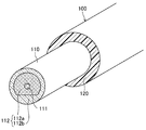
図1は、実施形態に係る光ファイバ・エンドキャップ接合構造10を示す。本実施形態に係る光ファイバ・エンドキャップ接合構造10は、加工装置用のレーザガイド等の光ファイバ部品の出射端部或いは入射端部に構成される構造である。
FIG. 1 shows an optical fiber end
本実施形態に係る光ファイバ・エンドキャップ接合構造10は、光ファイバ心線100とエンドキャップ20とによって構成されている。
An optical fiber / end
図2(a)及び(b)は、光ファイバ心線100を示す。
2A and 2B show the optical
光ファイバ心線100は、光ファイバ110とそれを被覆する例えばUV硬化型樹脂等で形成された被覆層120とを備える。レーザガイド用途で用いられる場合、光ファイバ心線100の長さは例えば5〜300mである。
The
光ファイバ110は、ファイバ中心をなす高屈折率のコア111とそれを被覆するように設けられた低屈折率のクラッド112とを有する。光ファイバ110の横断面形状は、典型的には円形であるが、楕円形状であってもよい。光ファイバ110のファイバ径は、例えば100〜2000μmであり、後述のコア111の変形抑制効果が顕著であるという観点から、好ましくは100〜750μm、より好ましくは100〜500μmである。
The
コア111は、例えば純粋石英や各種ドーパント(Er、Yb、Ndなどの希土類元素等)がドープされた石英で形成されており、その場合、屈折率が1.458である。コア111の横断面形状は、図2(a)に示すような円形であってもよく、その場合、コア径は例えば50〜1200μmである。また、コア111の横断面形状は、図2(b)に示すような方形であってもよく、その場合、その一辺の長さは例えば50〜1000μmである。
The
クラッド112は、例えば屈折率を低下させるフッ素やホウ素等がドープされた石英で形成されており、その場合、屈折率が例えば1.440〜1.454である。クラッド112の横断面形状は、通常は光ファイバ110の横断面形状に対応するが、典型的には円形である。クラッド112の層厚さは例えば3〜90μmである。
The
光ファイバ110は、図3に示すように、クラッド112がポンプガイドを構成する内側クラッド112aと外側クラッド112bとを有するダブルクラッド光ファイバであってもよい。
As shown in FIG. 3, the
光ファイバ110は、光ファイバ110全体が例えば純粋石英や各種ドーパントがドープされた石英で形成され、図4(a)に示すように、コア111とそれを囲うように配設された複数のエアホール113が形成されたクラッド112とを備えたものであってもよく、また、図4(b)に示すように、コア111とそれを被覆するように設けられたポンプガイドを構成する内側クラッド112aとそれを囲うように配設された複数のエアホール113が形成された外側クラッド112bとを備えたダブルクラッド光ファイバであってもよい。
The entire
光ファイバ110は、クラッド112を被覆するように設けられたサポート層を有していてもよい。その場合、サポート層は、コア111と同様、例えば純粋石英で形成されていることが好ましく、その場合、屈折率が1.458である。サポート層の層厚さは例えば5〜60μmである。
The
図5は、エンドキャップ20の一例を示す。
FIG. 5 shows an example of the
エンドキャップ20は、例えば純粋石英や各種ドーパントがドープされた石英で形成されているが、エンドキャップ20と光ファイバ110のコア111との間に光を反射させる界面が形成されるのを防止する観点から、光ファイバ110のコア111と同一材質で形成されていることが好ましい。エンドキャップ20の形状は、特に限定されるものではなく、図4に示すような円柱等のブロック状であってもよく、また、特許文献1に開示されたようなボトルネック形状部分を有するものであってもよい。エンドキャップ20の入射端側或いは出射端側のキャップ端面は、例えば、HfO2−SiO2膜、Ta2O5−SiO2膜、Al2O3−SiO2膜、Nb2O5−SiO2膜等のARコート(Anti Reflection coating)で被覆されていてもよい。エンドキャップ20の側面は、サンドブラスト等の処理が施されて表面が荒らされていてもよく、その場合、外部から入射した迷光等を、内部で反射させることなく外部に逃がすことができる。エンドキャップ20は、例えば図4に示す円柱状のものの場合、長さが5〜50mm及び外径が3〜40mmである。
The
本実施形態に係る光ファイバ・エンドキャップ接合構造10は、光ファイバ心線100の一方のファイバ端部において被覆層120が例えば10〜150mm程度剥離されて光ファイバ110が露出し、その露出した光ファイバ110のファイバ端面がエンドキャップ20に溶融接合した構成を有する。また、本実施形態に係る光ファイバ・エンドキャップ接合構造10は、光ファイバ110の接合側端部を被覆する被覆部材30を備え、その被覆部材30が光ファイバ110と共にエンドキャップ20に溶融接合した構成を有する。
In the optical fiber end
本実施形態に係る光ファイバ・エンドキャップ接合構造10によれば、光ファイバ110と共にその接合側端部を被覆するように設けられた被覆部材30がエンドキャップ20に溶融接合しているので、被覆部材30によって光ファイバ110側の熱容量が大きくなり、それによって後述の接合時の熱による光ファイバ110の接合側のファイバ端面のコア111の変形を抑制することができる。
According to the optical fiber / end
図6(a)〜(e)は、被覆部材30を示す。
6A to 6E show the covering
被覆部材30は、例えば純粋石英或いは軟化点を低下させる金属等がドープされた石英で形成されている。被覆部材30は、エンドキャップ20と同一材質で形成されていてもよい。被覆部材30の軟化点は、エンドキャップ20の軟化点と同一であってもよく、また、エンドキャップ20の軟化点よりも低くてもよく、さらに、エンドキャップ20の軟化点よりも高くてもよい。
The covering
被覆部材30の形状は、特に限定されるものではないが、例えば、図6(a)に示すような光ファイバ110を内嵌めすることができる貫通孔31が形成された筒状に形成されていてもよく、この場合、例えば、外径が0.5〜2mm及び高さが5〜150mmである。また、筒状の被覆部材30は、図6(b)に示すようなエンドキャップ20との接合部から光ファイバ110の延びる向きに先細った円錐台或いは図6(c)に示すような角錐台等の形状に形成されていてもよい。
The shape of the covering
被覆部材30の形状は、図6(d)に示すような光ファイバ110を内嵌めすることができる貫通孔31が形成された円盤状に形成されていてもよく、この場合、例えば、外径が0.5〜2mm及び厚さが0.5〜5mmである。
The shape of the covering
被覆部材30の形状は、図6(e)に示すような光ファイバ110を側方から覆うように設けられる帯状に形成されていてもよく、この場合、例えば厚さが0.5〜2mmである。
The shape of the covering
被覆部材30は、光ファイバ110と共にエンドキャップ20に接合するが、光ファイバ110側の熱容量を大きくして光ファイバ110の接合側のファイバ端面のコア111の変形を抑制する観点から、その接合面積、つまり、エンドキャップ20との接触面積が、光ファイバ110のエンドキャップ20への接合面積よりも大きいことが好ましい。具体的には、被覆部材30の接合面積は、光ファイバ110の接合面積の好ましくは2〜10倍であり、より好ましくは2〜4倍である。
The covering
被覆部材30は、光ファイバ110の外周部と接触しているのみであって溶融一体化していない態様であってもよく、また逆に、光ファイバ110の外周部と溶融一体化している態様であってもよい。コア111の変形を抑制する観点からは、光ファイバ110に必要以上の熱が与えられない前者の構成が好ましい。
The covering
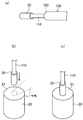
次に、本実施形態に係る光ファイバ・エンドキャップ接合構造10について図7(a)〜(c)に基づいて説明する。
Next, the optical fiber end
まず、光ファイバ心線100及びエンドキャップ20を準備し、光ファイバ心線100の接合側の被覆層120を所定長剥離して光ファイバ110を露出させる。
First, the optical
次いで、光ファイバ110の接合側のファイバ端面及びエンドキャップ20の接合面21を光学研磨する。ここで、光学研磨手段としては、例えば、研磨材による研磨、火炎照射等が挙げられる。
Next, the fiber end surface on the bonding side of the
続いて、図7(a)に示すように、光ファイバ110の接合側端部を被覆するように被覆部材30を設ける。
Subsequently, as illustrated in FIG. 7A, a covering
次いで、図7(b)に示すように、エンドキャップ20の接合面21に対して斜め横方向からレーザ光を照射すると共に、エンドキャップ20の接合面21に、被覆部材30を設けた光ファイバ110を突き当てるように当接させる。このとき、エンドキャップ20の接合面21の表層部は溶融し、その溶融したエンドキャップ20の接合面21に光ファイバ110及び被覆部材30が当接して溶融接合する。ここで、光ファイバ110の接合側のファイバ端面のコア111の変形を抑制する観点からは、光ファイバ110及び被覆部材30の接合面は加熱溶融させないことが好ましい。レーザ光源としては、例えばCO2レーザ等が挙げられ、レーザ光の波長は5〜11μmが好ましい。なお、レーザ光の照射は、エンドキャップ20の接合面21を水平面にして行ってもよく、また、エンドキャップ20の接合面21を垂直面にして行ってもよい。レーザ光の照射は、一方向から行ってもよく、また、複数方向から行ってもよい。
Next, as shown in FIG. 7B, an optical fiber in which a laser beam is irradiated obliquely from the lateral direction with respect to the joining
そして、図7(c)に示すように、エンドキャップ20の接合面21への光ファイバ110及び被覆部材30の当接と同時にレーザ光の照射を停止して冷却することにより本実施形態に係る光ファイバ・エンドキャップ接合構造10が構成される。
Then, as shown in FIG. 7C, the laser beam irradiation is stopped and cooled simultaneously with the contact of the
ところで、従来のように被覆部材30を用いずに、エンドキャップ20に光ファイバ110を溶融接合させた構成では、接合時に、光ファイバ110の先端の方が早く溶融して接合前に変形してしまい、それによって光ファイバ110の接合側のファイバ端面のコア111も変形するため、例えばエンドキャップ20を出射端としてレーザ光を出射した場合、コア111の横断面形状が円形であれば図8(a)に示すように、また、コア111の横断面形状が方形であれば図8(b)に示すように、放射パターンrを含む出射光パターンPが得られることがある。しかしながら、本実施形態に係る光ファイバ・エンドキャップ接合構造10によれば、光ファイバ110と共にその接合側端部を被覆するように設けられた被覆部材30がエンドキャップ20に溶融接合しているので、被覆部材30によって光ファイバ110側の熱容量が大きくなり、それによって接合時の熱による光ファイバ110の接合側のファイバ端面のコア111の変形を抑制することができる。その結果、例えばエンドキャップ20を出射端としてレーザ光を出射した場合でも、コア111の横断面形状が円形であれば図9(a)に示すように、また、コア111の横断面形状が方形であれば図9(b)に示すように、放射パターンを含まない良好な出射光パターンPを得ることができる。
By the way, in the configuration in which the
なお、本実施形態では、レーザ光を熱源として光ファイバ110とエンドキャップ20とを接合したが、特にこれに限定されるものではなく、エンドキャップ20の接合面21を垂直面にして火炎やプラズマを熱源としてエンドキャップ20の接合面21を溶融させてもよい。
In the present embodiment, the
(試験1)
<比較例1>
図2(a)に示すのと同様の構成のファイバ径500μm及びコア径200μmの石英製の光ファイバを備えた光ファイバ心線A、ファイバ径750μm及びコア径500μmの石英製の光ファイバを備えた光ファイバ心線B、並びにファイバ径1000μm及びコア径750μmの石英製の光ファイバを備えた光ファイバ心線Cを準備すると共に、図5に示すのと同様の構成の長さ15mm及び外径8mmの円柱状の石英製のエンドキャップを3個準備した。
(Test 1)
<Comparative Example 1>
An optical fiber core A including a quartz optical fiber having a fiber diameter of 500 μm and a core diameter of 200 μm, and a quartz optical fiber having a fiber diameter of 750 μm and a core diameter of 500 μm, having the same configuration as shown in FIG. And an optical fiber core C having an optical fiber made of quartz having a fiber diameter of 1000 μm and a core diameter of 750 μm, a length of 15 mm and an outer diameter of the same configuration as shown in FIG. Three 8 mm cylindrical end caps made of quartz were prepared.
光ファイバ心線A〜Cのそれぞれについて、接合側の被覆層を所定長剥離して光ファイバを露出させ、その接合側のファイバ端面に光学研磨を施した。また、各エンドキャップの一方の面(接合面)にも光学研磨を施した。 For each of the optical fiber cores A to C, the coating layer on the bonding side was peeled off for a predetermined length to expose the optical fiber, and the fiber end surface on the bonding side was optically polished. Also, one surface (bonding surface) of each end cap was optically polished.
エンドキャップの光学研磨を施した接合面にCO2レーザからの波長10.6μmのレーザ光を斜め横方向から照射して表層部を溶融させ、そこに光ファイバ心線Aの光ファイバを突き当てるように当接させ、それと同時にレーザ光の照射を遮断した。これにより光ファイバ心線Aの光ファイバ・エンドキャップ接合構造を得た。また同様に、光ファイバ心線B及びCの光ファイバ・エンドキャップ接合構造を得た。 A laser beam having a wavelength of 10.6 μm from a CO 2 laser is irradiated from an oblique lateral direction to the joining surface of the end cap subjected to optical polishing to melt the surface layer portion, and the optical fiber of the optical fiber core A is abutted there. At the same time, the laser beam was cut off. As a result, an optical fiber end cap joining structure of the optical fiber core A was obtained. Similarly, optical fiber end cap joining structures of optical fiber cores B and C were obtained.
これらの光ファイバ心線A〜Cのそれぞれの光ファイバ・エンドキャップ接合構造について、光ファイバとエンドキャップとの接合部を観察したところ、いずれも光ファイバ先端の側面部が少し変形した形態が認められた。ファイバ径が750μmの光ファイバ心線B及びファイバ径が1000μmの光ファイバ心線Cの光ファイバ・エンドキャップ接合構造では、光ファイバのクラッドの変形は認められたものの、コアの変形は認められなかった。一方、ファイバ径が500μmの光ファイバ心線Aの光ファイバ・エンドキャップ接合構造では、光ファイバのクラッドのみならず、コアの変形も認められた。 For each of the optical fiber end cap joint structures of these optical fiber cores A to C, when the joint portion between the optical fiber and the end cap was observed, a form in which the side surface portion at the tip of the optical fiber was slightly deformed was recognized. It was. In the optical fiber end cap joint structure of the optical fiber core wire B having a fiber diameter of 750 μm and the optical fiber core wire C having a fiber diameter of 1000 μm, although deformation of the cladding of the optical fiber was observed, deformation of the core was not recognized. It was. On the other hand, in the optical fiber end cap junction structure of the optical fiber core wire A having a fiber diameter of 500 μm, not only the cladding of the optical fiber but also the deformation of the core was recognized.
光ファイバ心線A〜Cのそれぞれの光ファイバ・エンドキャップ接合構造について、光ファイバにHe-Neレーザからの波長633nmのレーザ光を伝送させてエンドキャップを介して得られる出射光パターンを評価したところ、ファイバ径が750μmの光ファイバ心線B及びファイバ径が1000μmを用いた光ファイバ心線Cの光ファイバ・エンドキャップ接合構造では、図9(a)に示すような歪みのない出射光パターンPが得られた。一方、ファイバ径が500μmの光ファイバ心線Aの光ファイバ・エンドキャップ接合構造では、図8(a)に示すような放射パターンrを含む出射光パターンPが得られた。 For each of the optical fiber end cap joint structures of the optical fiber cores A to C, the laser beam having a wavelength of 633 nm from the He—Ne laser was transmitted to the optical fiber, and the emitted light pattern obtained through the end cap was evaluated. However, in the optical fiber end cap joining structure of the optical fiber core B having a fiber diameter of 750 μm and the optical fiber core C having a fiber diameter of 1000 μm, an outgoing light pattern without distortion as shown in FIG. P was obtained. On the other hand, in the optical fiber end cap junction structure of the optical fiber core A having a fiber diameter of 500 μm, an outgoing light pattern P including a radiation pattern r as shown in FIG.
<実施例1>
図2(a)に示すのと同様の構成のファイバ径500μm及びコア径200μmの石英製の光ファイバを備えた光ファイバ心線A、図5に示すのと同様の構成の長さ15mm及び外径8mmの円柱状の石英製のエンドキャップ、並びに図6(a)に示すのと同様の構成の外径1000μm、内径500μm、及び長さ2mmの円筒状の石英製の被覆部材を準備した。
<Example 1>
An optical fiber core A comprising a quartz optical fiber having a fiber diameter of 500 μm and a core diameter of 200 μm having the same configuration as shown in FIG. 2A, a length of 15 mm and an outer configuration having the same configuration as shown in FIG. A cylindrical quartz end cap having a diameter of 8 mm and a cylindrical quartz covering member having an outer diameter of 1000 μm, an inner diameter of 500 μm, and a length of 2 mm having the same configuration as shown in FIG. 6A were prepared.
光ファイバ心線Aの接合側の被覆層を所定長剥離して光ファイバを露出させ、その接合側のファイバ端面に光学研磨を施した。また、エンドキャップの一方の面(接合面)にも光学研磨を施した。 The coating layer on the bonding side of the optical fiber core A was peeled for a predetermined length to expose the optical fiber, and the fiber end surface on the bonding side was optically polished. Also, one surface (bonding surface) of the end cap was optically polished.
上記実施形態と同様、露出した光ファイバの接合側端部を被覆部材に内嵌めして被覆し、そして、エンドキャップの光学研磨を施した接合面にCO2レーザからの波長10.6μmのレーザ光を斜め横方向から照射して表層部を溶融させ、そこに光ファイバ心線Aの光ファイバ及び被覆部材を突き当てるように当接させ、それと同時にレーザ光の照射を遮断した。これにより被覆部材を用いた光ファイバ心線Aの光ファイバ・エンドキャップ接合構造を得た。 As in the above embodiment, the joint end of the exposed optical fiber is fitted on the covering member to cover the end surface, and the end cap is subjected to optical polishing with a laser of 10.6 μm wavelength from the CO 2 laser. The surface layer portion was melted by irradiating light obliquely from the lateral direction, and the optical fiber of the optical fiber core A and the covering member were brought into contact with each other, and at the same time, the laser beam irradiation was cut off. As a result, an optical fiber end cap joining structure of the optical fiber core A using the covering member was obtained.
この被覆部材を用いた光ファイバ心線Aの光ファイバ・エンドキャップ接合構造について、光ファイバとエンドキャップとの接合部を観察したところ、コアの変形は認められなかった。また、光ファイバにHe-Neレーザからの波長633nmのレーザ光を伝送させてエンドキャップを介して得られる出射光パターンを評価したところ、図9(a)に示すような歪みのない良好な出射光パターンPが得られた。 With respect to the optical fiber end cap bonding structure of the optical fiber core A using this covering member, no deformation of the core was observed when the bonded portion between the optical fiber and the end cap was observed. In addition, when a laser beam having a wavelength of 633 nm from a He—Ne laser was transmitted to an optical fiber and an emitted light pattern obtained through an end cap was evaluated, a good output without distortion as shown in FIG. 9A was obtained. A light emission pattern P was obtained.
また、図2(a)に示すのと同様の構成のファイバ径1000μm及びコア径750μmの石英製の光ファイバを備えた光ファイバ心線C、図5に示すのと同様の構成の長さ15mm及び外径8mmの円柱状の石英製のエンドキャップ、並びに図6(a)に示すのと同様の構成の外径1400μm、内径1000μm、及び長さ2mmの円筒状の石英製の被覆部材を用いた光ファイバ・エンドキャップ接合構造についても同じ試験結果が得られた。 Also, an optical fiber core C having an optical fiber made of quartz having a fiber diameter of 1000 μm and a core diameter of 750 μm having the same configuration as shown in FIG. 2A, and a length of 15 mm having the same configuration as shown in FIG. And a cylindrical quartz end cap having an outer diameter of 8 mm, and a cylindrical quartz covering member having an outer diameter of 1400 μm, an inner diameter of 1000 μm, and a length of 2 mm having the same configuration as shown in FIG. The same test results were obtained for the optical fiber end cap joint structure.
(試験2)
<比較例2>
図2(b)に示すのと同様の構成のファイバ径500μmで且つ50μ×150μmの方形のコアを有する石英製の光ファイバを備えた光ファイバ心線D、並びに図5に示すのと同様の構成の長さ15mm及び外径8mmの円柱状の石英製のエンドキャップを準備した。
(Test 2)
<Comparative Example 2>
An optical fiber core D having an optical fiber made of quartz having a square core with a fiber diameter of 500 μm and 50 μ × 150 μm having the same configuration as shown in FIG. 2B, and the same as shown in FIG. A cylindrical quartz end cap having a length of 15 mm and an outer diameter of 8 mm was prepared.
光ファイバ心線Aの接合側の被覆層を所定長剥離して光ファイバを露出させ、そのファイバ端面に光学研磨を施した。また、エンドキャップの一方の面(接合面)にも光学研磨を施した。 The coating layer on the bonding side of the optical fiber core A was peeled off for a predetermined length to expose the optical fiber, and the fiber end face was optically polished. Also, one surface (bonding surface) of the end cap was optically polished.
エンドキャップの光学研磨を施した接合面にCO2レーザからの波長10.6μmのレーザ光を斜め横方向から照射して表層部を溶融させ、そこに光ファイバ心線Dの光ファイバを突き当てるように当接させ、それと同時にレーザ光の照射を遮断した。これにより光ファイバ心線Dの光ファイバ・エンドキャップ接合構造を得た。 The optically polished end cap is irradiated with laser light having a wavelength of 10.6 μm from a CO 2 laser in an oblique lateral direction to melt the surface layer portion, and the optical fiber of the optical fiber core D is abutted there. At the same time, the laser beam was cut off. As a result, an optical fiber end cap joining structure of the optical fiber core D was obtained.
この光ファイバ心線Dの光ファイバ・エンドキャップ接合構造について、光ファイバとエンドキャップとの接合部を観察したところ、光ファイバの先端の変形が認められた。なお、上記試行を複数回繰り返したが、接合時に光ファイバの先端が変形したり、また、接合前に光ファイバの先端が溶融により変形して接合不可となった場合があった。 With respect to the optical fiber end cap joint structure of the optical fiber core D, when the joint between the optical fiber and the end cap was observed, deformation of the tip of the optical fiber was observed. Although the above trial was repeated a plurality of times, there was a case where the tip of the optical fiber was deformed at the time of joining, or the tip of the optical fiber was deformed by melting before joining, and joining was impossible.
光ファイバ心線Dの光ファイバ・エンドキャップ接合構造について、光ファイバにHe-Neレーザからの波長633nmのレーザ光を伝送させてエンドキャップを介して得られる出射光パターンを評価したところ、図8(b)に示すような放射パターンrを含む出射光パターンPが得られた。 With respect to the optical fiber end cap joint structure of the optical fiber core D, when the laser beam having a wavelength of 633 nm from the He—Ne laser is transmitted to the optical fiber and the emitted light pattern obtained through the end cap is evaluated, FIG. An outgoing light pattern P including a radiation pattern r as shown in (b) was obtained.
<実施例2>
図2(b)に示すのと同様の構成のファイバ径500μmで且つ50μ×150μmの方形のコアを有する石英製の光ファイバを備えた光ファイバ心線D、図5に示すのと同様の構成の長さ15mm及び外径8mmの円柱状の石英製のエンドキャップ、並びに図6(a)に示すのと同様の構成の外径1000μm、内径500μm、及び長さ2mmの円筒状の石英製の被覆部材を準備した。
<Example 2>
An optical fiber core D having an optical fiber made of quartz having a fiber core of 500 μm and a square core of 50 μ × 150 μm having the same configuration as shown in FIG. 2B, the same configuration as shown in FIG. A cylindrical quartz end cap having a length of 15 mm and an outer diameter of 8 mm, and a cylindrical quartz end cap having the same configuration as shown in FIG. 6A and an outer diameter of 1000 μm, an inner diameter of 500 μm, and a length of 2 mm. A covering member was prepared.
光ファイバ心線Aの接合側の被覆層を所定長剥離して光ファイバを露出させ、そのファイバ端面に光学研磨を施した。また、エンドキャップの一方の面(接合面)にも光学研磨を施した。 The coating layer on the bonding side of the optical fiber core A was peeled off for a predetermined length to expose the optical fiber, and the fiber end face was optically polished. Also, one surface (bonding surface) of the end cap was optically polished.
上記実施形態と同様、露出した光ファイバの接合側端部を被覆部材に内嵌めして被覆し、そして、エンドキャップの光学研磨を施した接合面にCO2レーザからの波長10.6μmのレーザ光を斜め横方向から照射して表層部を溶融させ、そこに光ファイバ心線Dの光ファイバ及び被覆部材を突き当てるように当接させ、それと同時にレーザ光の照射を遮断した。これにより被覆部材を用いた光ファイバ心線Dの光ファイバ・エンドキャップ接合構造を得た。 As in the above embodiment, the joint end of the exposed optical fiber is fitted on the covering member to cover the end surface, and the end cap is subjected to optical polishing with a laser of 10.6 μm wavelength from the CO 2 laser. The surface layer portion was melted by irradiating light obliquely from the lateral direction, and the optical fiber of the optical fiber core D and the covering member were brought into contact with each other, and at the same time, the irradiation of the laser beam was cut off. As a result, an optical fiber end cap joining structure of the optical fiber core D using the covering member was obtained.
この被覆部材を用いた光ファイバ心線Dの光ファイバ・エンドキャップ接合構造について、光ファイバとエンドキャップとの接合部を観察したところ、コアの変形は認められなかった。また、光ファイバにHe-Neレーザからの波長633nmのレーザ光を伝送させてエンドキャップを介して得られる出射光パターンを評価したところ、図9(b)に示すような歪みのない良好な出射光パターンPが得られた。 With respect to the optical fiber end cap bonding structure of the optical fiber core D using this covering member, when the bonded portion between the optical fiber and the end cap was observed, no deformation of the core was observed. In addition, when a laser beam having a wavelength of 633 nm from a He—Ne laser was transmitted to an optical fiber and an emitted light pattern obtained through an end cap was evaluated, a good output without distortion as shown in FIG. 9B was obtained. A light emission pattern P was obtained.
(試験3)
<実施例3>
図4(b)に示すのと同様の構成のファイバ径1000μm、コア径60μm、エアホール内側のポンプガイド径600μmのコアにYbがドープされた石英製のダブルクラッド光ファイバを備えた光ファイバ心線E、図5に示すのと同様の構成の長さ15mm及び外径8mmの円柱状の石英製のエンドキャップ2個、並びに図6(a)に示すのと同様の構成の外径1000μm、内径500μm、及び長さ2mmの円筒状の石英製の被覆部材2個を準備した。
(Test 3)
<Example 3>
An optical fiber core including a double clad optical fiber made of quartz in which Yb is doped in a core having a fiber diameter of 1000 μm, a core diameter of 60 μm, and a pump guide diameter of 600 μm inside the air hole, having the same configuration as shown in FIG. Line E, two cylindrical quartz end caps having a length of 15 mm and an outer diameter of 8 mm having the same configuration as shown in FIG. 5, and an outer diameter of 1000 μm having the same configuration as shown in FIG. Two cylindrical quartz covering members having an inner diameter of 500 μm and a length of 2 mm were prepared.
光ファイバ心線Eの両側の被覆層を所定長剥離してダブルクラッド光ファイバを露出させ、それぞれのファイバ端面に光学研磨を施した。また、各エンドキャップの一方の面(接合面)にも光学研磨を施した。 The coating layers on both sides of the optical fiber core E were peeled for a predetermined length to expose the double-clad optical fiber, and each fiber end face was optically polished. Also, one surface (bonding surface) of each end cap was optically polished.
上記実施形態と同様、露出したダブルクラッド光ファイバの両方の接合側端部のそれぞれを被覆部材に内嵌めして被覆し、そして、それぞれの接合側端部について、エンドキャップの光学研磨を施した接合面にCO2レーザからの波長10.6μmのレーザ光を斜め横方向から照射して表層部を溶融させ、そこに光ファイバ心線Eのダブルクラッド光ファイバ及び被覆部材を突き当てるように当接させ、それと同時にレーザ光の照射を遮断した。これにより両端部に被覆部材を用いた光ファイバ心線Eの光ファイバ・エンドキャップ接合構造が構成された光ファイバ部品を得た。 As in the above embodiment, each of the joint-side end portions of both exposed double-clad optical fibers is covered with a covering member and covered, and the end cap is optically polished for each joint-side end portion. The joint surface is irradiated with laser light having a wavelength of 10.6 μm from a CO 2 laser from an oblique lateral direction to melt the surface layer portion, and the double-clad optical fiber of the optical fiber core E and the covering member are abutted there. At the same time, the laser beam was cut off. As a result, an optical fiber component in which the optical fiber end cap joining structure of the optical fiber core E using the covering members at both ends was formed was obtained.
この光ファイバ部品について、ダブルクラッド光ファイバとエンドキャップとの接合部を観察したところ、光ファイバ先端の変形も、また、エアホールの変形も認められなかった。 When this optical fiber component was observed at the joint between the double clad optical fiber and the end cap, neither deformation of the tip of the optical fiber nor deformation of the air hole was observed.
また、この光ファイバ部品と外部共振器ミラーとを組み合わせてレーザ発振器を構成し、これを用いてレーザ発振実験を行ったところ、エンドキャップを接合していない光ファイバ心線E単独の場合と同等の発振特性が確認された。つまり、このことは被覆部材を用いてダブルクラッド光ファイバをエンドキャップに接合した構造がレーザ発振特性に悪影響を及ぼさないことを意味するものである。また、この被覆部材を用いてダブルクラッド光ファイバをエンドキャップに接合した光ファイバ部品を用いれば、kW級のレーザ発振を行ってもレーザ光の出射端面であるエンドキャップ端面が破壊することなく、信頼性の高いレーザ発振が行われることも確認した。 In addition, when a laser oscillator was configured by combining this optical fiber component and an external resonator mirror, and a laser oscillation experiment was performed using the laser oscillator, it was the same as the case of the optical fiber core E alone with no end cap bonded. The oscillation characteristics were confirmed. That is, this means that the structure in which the double clad optical fiber is bonded to the end cap using the covering member does not adversely affect the laser oscillation characteristics. In addition, if an optical fiber component in which a double-clad optical fiber is joined to an end cap using this covering member is used, the end cap end surface, which is the laser light emitting end surface, is not destroyed even when kW-class laser oscillation is performed. It was also confirmed that highly reliable laser oscillation was performed.
本発明は、光ファイバ・エンドキャップ接合構造及びその製造方法について有用である。 INDUSTRIAL APPLICABILITY The present invention is useful for an optical fiber end cap joining structure and a manufacturing method thereof.
100 光ファイバ・エンドキャップ接合構造
110 光ファイバ心線
110 光ファイバ
111 コア
112 クラッド
112a 内側クラッド
112b 外側クラッド
113 エアホール
120 被覆層
20 エンドキャップ
21 接合面
30 被覆部材
31 貫通孔
DESCRIPTION OF
Claims (5)
上記光ファイバの接合側端部を被覆し且つ該光ファイバと共に上記エンドキャップに突き当てられて溶融接合した被覆部材を備え、
上記被覆部材の上記エンドキャップへの接合面積が、上記光ファイバの上記エンドキャップへの接合面積よりも大きく、
上記被覆部材は、上記光ファイバの外周部と接触しているのみであって溶融一体化していない光ファイバ・エンドキャップ接合構造。 An optical fiber end cap bonding structure in which the fiber end surface of the optical fiber exposed by peeling off the coating layer at one fiber end of the optical fiber core is melt bonded to the end cap,
E Bei the shield in the molten bonding is abutted against the end cap of the connecting-side end portion with coated and optical fiber of the optical fiber,
The bonding area of the covering member to the end cap is larger than the bonding area of the optical fiber to the end cap,
An optical fiber end cap joining structure in which the covering member is only in contact with the outer peripheral portion of the optical fiber and is not fused and integrated .
上記被覆部材は、上記光ファイバを内嵌めすることができる貫通孔が形成された筒状に形成されている光ファイバ・エンドキャップ接合構造。 In the optical fiber end cap joining structure according to claim 1,
The said covering member is an optical fiber end cap joining structure currently formed in the cylinder shape in which the through-hole which can fit the said optical fiber was formed.
上記被覆部材は、上記エンドキャップとの接合部から上記光ファイバの延びる向きに先細った形状に形成されている光ファイバ・エンドキャップ接合構造。 In the optical fiber end cap joining structure according to claim 1 or 2,
The covering member is an optical fiber / end cap joining structure formed in a shape tapered from a joint portion with the end cap in a direction in which the optical fiber extends.
上記被覆部材は、上記エンドキャップと同一材質で形成されている光ファイバ・エンドキャップ接合構造。 In the optical fiber end cap joining structure according to any one of claims 1 to 3,
The covering member is an optical fiber / end cap joining structure formed of the same material as the end cap.
光ファイバの接合側端部を被覆するように被覆部材を設け、一方、エンドキャップの接合予定部を、外部から熱を与えて溶融させ、そして、該エンドキャップの溶融した接合予定部に該光ファイバと共に該被覆部材を突き当てて溶融接合させる光ファイバ・エンドキャップ接合構造の製造方法。 A method for manufacturing an optical fiber endcap joining structure according to any one of claims 1 to 4 ,
A covering member is provided so as to cover the end portion of the optical fiber on the bonding side, while the end cap joining portion of the end cap is melted by applying heat from the outside, and the end portion of the end cap is melted with the light. A method of manufacturing an optical fiber end cap bonding structure in which a coating member is abutted with a fiber and melt-bonded.
Priority Applications (1)
| Application Number | Priority Date | Filing Date | Title |
|---|---|---|---|
| JP2012073570A JP5902016B2 (en) | 2012-03-28 | 2012-03-28 | Optical fiber end cap joint structure and manufacturing method thereof |
Applications Claiming Priority (1)
| Application Number | Priority Date | Filing Date | Title |
|---|---|---|---|
| JP2012073570A JP5902016B2 (en) | 2012-03-28 | 2012-03-28 | Optical fiber end cap joint structure and manufacturing method thereof |
Publications (2)
| Publication Number | Publication Date |
|---|---|
| JP2013205573A JP2013205573A (en) | 2013-10-07 |
| JP5902016B2 true JP5902016B2 (en) | 2016-04-13 |
Family
ID=49524730
Family Applications (1)
| Application Number | Title | Priority Date | Filing Date |
|---|---|---|---|
| JP2012073570A Active JP5902016B2 (en) | 2012-03-28 | 2012-03-28 | Optical fiber end cap joint structure and manufacturing method thereof |
Country Status (1)
| Country | Link |
|---|---|
| JP (1) | JP5902016B2 (en) |
Families Citing this family (6)
| Publication number | Priority date | Publication date | Assignee | Title |
|---|---|---|---|---|
| US10069270B2 (en) | 2016-02-11 | 2018-09-04 | Raytheon Company | Planar waveguides with enhanced support and/or cooling features for high-power laser systems |
| JP2018004772A (en) * | 2016-06-28 | 2018-01-11 | 株式会社フジクラ | Optical device and laser apparatus |
| IL256688B (en) | 2018-01-01 | 2020-03-31 | Wormser Daniel | Endcap, assembly and method for improving accuracy in fiber-endcap-fixture alignment |
| CN110045463B (en) * | 2018-01-15 | 2021-09-07 | 中国科学院上海光学精密机械研究所 | Connecting piece and method for optical fiber fusion |
| JP2020126157A (en) * | 2019-02-05 | 2020-08-20 | 株式会社フジクラ | Manufacturing method, structure, laser device, and laser system |
| JP7228429B2 (en) * | 2019-03-20 | 2023-02-24 | 三菱電線工業株式会社 | Optical fiber for laser light transmission |
Family Cites Families (4)
| Publication number | Priority date | Publication date | Assignee | Title |
|---|---|---|---|---|
| JPH036610U (en) * | 1990-03-16 | 1991-01-23 | ||
| JP2003084167A (en) * | 2001-09-13 | 2003-03-19 | Fujikura Ltd | Collimator |
| JP2004264843A (en) * | 2003-02-14 | 2004-09-24 | Fujikura Ltd | Optical fiber with optical function element, and method and device for manufacturing same |
| JP4878259B2 (en) * | 2006-10-20 | 2012-02-15 | 浜松ホトニクス株式会社 | Optical components |
-
2012
- 2012-03-28 JP JP2012073570A patent/JP5902016B2/en active Active
Also Published As
| Publication number | Publication date |
|---|---|
| JP2013205573A (en) | 2013-10-07 |
Similar Documents
| Publication | Publication Date | Title |
|---|---|---|
| JP5902016B2 (en) | Optical fiber end cap joint structure and manufacturing method thereof | |
| US8064742B2 (en) | Light input/output terminal module of the optical components and beam converting apparatus | |
| WO2009090712A1 (en) | Optical fiber | |
| US9213140B2 (en) | Fiber component and laser device | |
| JP4878259B2 (en) | Optical components | |
| US8023785B2 (en) | Laser guide optical fiber and laser guide including the same | |
| TW201617659A (en) | Optical assembly and method for producing and using the same | |
| WO2018003604A1 (en) | Optical device and laser device | |
| WO2015076105A1 (en) | Method for manufacturing bent optical fiber | |
| TWI652516B (en) | Fiber optic device | |
| JP2013007959A (en) | End face processing method of optical fiber and terminal structure of optical fiber | |
| JP2009124014A (en) | Method for manufacturing optical combiner | |
| JP4620626B2 (en) | Optical fiber structure and block chip used therefor | |
| JP2018004770A (en) | Optical device and laser apparatus | |
| US7508848B2 (en) | Method and configurations in achieving high energy operation for photonic band gap (PGB) fiber with end caps | |
| JP4664271B2 (en) | Optical fiber and manufacturing method thereof | |
| JP2015210306A (en) | Optical connector and manufacturing method therefor | |
| JP2018036361A (en) | Optical fiber bundle, combiner, laser device, and method of manufacturing optical fiber bundle | |
| JP6243641B2 (en) | Manufacturing method of glass structure | |
| WO2011004539A1 (en) | Structure of binding multiple cores of optical fibers and method for manufacturing same | |
| JP2010232634A (en) | Optical combiner and fiber laser using the same | |
| JP4882786B2 (en) | Bundle fiber manufacturing method | |
| JP5095652B2 (en) | Optical combiner | |
| JP5042964B2 (en) | Optical fiber and manufacturing method thereof | |
| JP7197265B2 (en) | Joining member using additive manufacturing |
Legal Events
| Date | Code | Title | Description |
|---|---|---|---|
| A621 | Written request for application examination |
Free format text: JAPANESE INTERMEDIATE CODE: A621 Effective date: 20150227 |
|
| A131 | Notification of reasons for refusal |
Free format text: JAPANESE INTERMEDIATE CODE: A131 Effective date: 20150929 |
|
| A977 | Report on retrieval |
Free format text: JAPANESE INTERMEDIATE CODE: A971007 Effective date: 20150930 |
|
| A521 | Request for written amendment filed |
Free format text: JAPANESE INTERMEDIATE CODE: A523 Effective date: 20151130 |
|
| A131 | Notification of reasons for refusal |
Free format text: JAPANESE INTERMEDIATE CODE: A131 Effective date: 20151222 |
|
| A521 | Request for written amendment filed |
Free format text: JAPANESE INTERMEDIATE CODE: A523 Effective date: 20160121 |
|
| TRDD | Decision of grant or rejection written | ||
| A01 | Written decision to grant a patent or to grant a registration (utility model) |
Free format text: JAPANESE INTERMEDIATE CODE: A01 Effective date: 20160209 |
|
| A61 | First payment of annual fees (during grant procedure) |
Free format text: JAPANESE INTERMEDIATE CODE: A61 Effective date: 20160309 |
|
| R150 | Certificate of patent or registration of utility model |
Ref document number: 5902016 Country of ref document: JP Free format text: JAPANESE INTERMEDIATE CODE: R150 |
|
| R250 | Receipt of annual fees |
Free format text: JAPANESE INTERMEDIATE CODE: R250 |
|
| R250 | Receipt of annual fees |
Free format text: JAPANESE INTERMEDIATE CODE: R250 |
|
| R250 | Receipt of annual fees |
Free format text: JAPANESE INTERMEDIATE CODE: R250 |
|
| R250 | Receipt of annual fees |
Free format text: JAPANESE INTERMEDIATE CODE: R250 |
|
| R250 | Receipt of annual fees |
Free format text: JAPANESE INTERMEDIATE CODE: R250 |