JP5894203B2 - Supercharger manufacturing method - Google Patents
Supercharger manufacturing method Download PDFInfo
- Publication number
- JP5894203B2 JP5894203B2 JP2014042073A JP2014042073A JP5894203B2 JP 5894203 B2 JP5894203 B2 JP 5894203B2 JP 2014042073 A JP2014042073 A JP 2014042073A JP 2014042073 A JP2014042073 A JP 2014042073A JP 5894203 B2 JP5894203 B2 JP 5894203B2
- Authority
- JP
- Japan
- Prior art keywords
- motor
- housing
- supercharger
- stator
- rotor
- Prior art date
- Legal status (The legal status is an assumption and is not a legal conclusion. Google has not performed a legal analysis and makes no representation as to the accuracy of the status listed.)
- Active
Links
Images


Classifications
-
- F—MECHANICAL ENGINEERING; LIGHTING; HEATING; WEAPONS; BLASTING
- F04—POSITIVE - DISPLACEMENT MACHINES FOR LIQUIDS; PUMPS FOR LIQUIDS OR ELASTIC FLUIDS
- F04D—NON-POSITIVE-DISPLACEMENT PUMPS
- F04D25/00—Pumping installations or systems
- F04D25/02—Units comprising pumps and their driving means
- F04D25/04—Units comprising pumps and their driving means the pump being fluid-driven
- F04D25/045—Units comprising pumps and their driving means the pump being fluid-driven the pump wheel carrying the fluid driving means, e.g. turbine blades
-
- F—MECHANICAL ENGINEERING; LIGHTING; HEATING; WEAPONS; BLASTING
- F02—COMBUSTION ENGINES; HOT-GAS OR COMBUSTION-PRODUCT ENGINE PLANTS
- F02B—INTERNAL-COMBUSTION PISTON ENGINES; COMBUSTION ENGINES IN GENERAL
- F02B37/00—Engines characterised by provision of pumps driven at least for part of the time by exhaust
- F02B37/04—Engines with exhaust drive and other drive of pumps, e.g. with exhaust-driven pump and mechanically-driven second pump
- F02B37/10—Engines with exhaust drive and other drive of pumps, e.g. with exhaust-driven pump and mechanically-driven second pump at least one pump being alternatively or simultaneously driven by exhaust and other drive, e.g. by pressurised fluid from a reservoir or an engine-driven pump
-
- F—MECHANICAL ENGINEERING; LIGHTING; HEATING; WEAPONS; BLASTING
- F01—MACHINES OR ENGINES IN GENERAL; ENGINE PLANTS IN GENERAL; STEAM ENGINES
- F01D—NON-POSITIVE DISPLACEMENT MACHINES OR ENGINES, e.g. STEAM TURBINES
- F01D15/00—Adaptations of machines or engines for special use; Combinations of engines with devices driven thereby
- F01D15/10—Adaptations for driving, or combinations with, electric generators
-
- F—MECHANICAL ENGINEERING; LIGHTING; HEATING; WEAPONS; BLASTING
- F02—COMBUSTION ENGINES; HOT-GAS OR COMBUSTION-PRODUCT ENGINE PLANTS
- F02B—INTERNAL-COMBUSTION PISTON ENGINES; COMBUSTION ENGINES IN GENERAL
- F02B39/00—Component parts, details, or accessories relating to, driven charging or scavenging pumps, not provided for in groups F02B33/00 - F02B37/00
- F02B39/02—Drives of pumps; Varying pump drive gear ratio
- F02B39/08—Non-mechanical drives, e.g. fluid drives having variable gear ratio
- F02B39/10—Non-mechanical drives, e.g. fluid drives having variable gear ratio electric
-
- F—MECHANICAL ENGINEERING; LIGHTING; HEATING; WEAPONS; BLASTING
- F04—POSITIVE - DISPLACEMENT MACHINES FOR LIQUIDS; PUMPS FOR LIQUIDS OR ELASTIC FLUIDS
- F04D—NON-POSITIVE-DISPLACEMENT PUMPS
- F04D17/00—Radial-flow pumps, e.g. centrifugal pumps; Helico-centrifugal pumps
- F04D17/08—Centrifugal pumps
- F04D17/10—Centrifugal pumps for compressing or evacuating
-
- F—MECHANICAL ENGINEERING; LIGHTING; HEATING; WEAPONS; BLASTING
- F04—POSITIVE - DISPLACEMENT MACHINES FOR LIQUIDS; PUMPS FOR LIQUIDS OR ELASTIC FLUIDS
- F04D—NON-POSITIVE-DISPLACEMENT PUMPS
- F04D25/00—Pumping installations or systems
- F04D25/02—Units comprising pumps and their driving means
- F04D25/024—Units comprising pumps and their driving means the driving means being assisted by a power recovery turbine
-
- F—MECHANICAL ENGINEERING; LIGHTING; HEATING; WEAPONS; BLASTING
- F04—POSITIVE - DISPLACEMENT MACHINES FOR LIQUIDS; PUMPS FOR LIQUIDS OR ELASTIC FLUIDS
- F04D—NON-POSITIVE-DISPLACEMENT PUMPS
- F04D25/00—Pumping installations or systems
- F04D25/02—Units comprising pumps and their driving means
- F04D25/06—Units comprising pumps and their driving means the pump being electrically driven
- F04D25/0606—Units comprising pumps and their driving means the pump being electrically driven the electric motor being specially adapted for integration in the pump
-
- F—MECHANICAL ENGINEERING; LIGHTING; HEATING; WEAPONS; BLASTING
- F04—POSITIVE - DISPLACEMENT MACHINES FOR LIQUIDS; PUMPS FOR LIQUIDS OR ELASTIC FLUIDS
- F04D—NON-POSITIVE-DISPLACEMENT PUMPS
- F04D29/00—Details, component parts, or accessories
- F04D29/18—Rotors
- F04D29/20—Mounting rotors on shafts
-
- F—MECHANICAL ENGINEERING; LIGHTING; HEATING; WEAPONS; BLASTING
- F04—POSITIVE - DISPLACEMENT MACHINES FOR LIQUIDS; PUMPS FOR LIQUIDS OR ELASTIC FLUIDS
- F04D—NON-POSITIVE-DISPLACEMENT PUMPS
- F04D29/00—Details, component parts, or accessories
- F04D29/26—Rotors specially for elastic fluids
- F04D29/266—Rotors specially for elastic fluids mounting compressor rotors on shafts
-
- F—MECHANICAL ENGINEERING; LIGHTING; HEATING; WEAPONS; BLASTING
- F04—POSITIVE - DISPLACEMENT MACHINES FOR LIQUIDS; PUMPS FOR LIQUIDS OR ELASTIC FLUIDS
- F04D—NON-POSITIVE-DISPLACEMENT PUMPS
- F04D29/00—Details, component parts, or accessories
- F04D29/60—Mounting; Assembling; Disassembling
- F04D29/62—Mounting; Assembling; Disassembling of radial or helico-centrifugal pumps
- F04D29/624—Mounting; Assembling; Disassembling of radial or helico-centrifugal pumps especially adapted for elastic fluid pumps
-
- H—ELECTRICITY
- H02—GENERATION; CONVERSION OR DISTRIBUTION OF ELECTRIC POWER
- H02K—DYNAMO-ELECTRIC MACHINES
- H02K1/00—Details of the magnetic circuit
- H02K1/06—Details of the magnetic circuit characterised by the shape, form or construction
- H02K1/12—Stationary parts of the magnetic circuit
- H02K1/18—Means for mounting or fastening magnetic stationary parts on to, or to, the stator structures
- H02K1/185—Means for mounting or fastening magnetic stationary parts on to, or to, the stator structures to outer stators
-
- H—ELECTRICITY
- H02—GENERATION; CONVERSION OR DISTRIBUTION OF ELECTRIC POWER
- H02K—DYNAMO-ELECTRIC MACHINES
- H02K15/00—Methods or apparatus specially adapted for manufacturing, assembling, maintaining or repairing of dynamo-electric machines
- H02K15/02—Methods or apparatus specially adapted for manufacturing, assembling, maintaining or repairing of dynamo-electric machines of stator or rotor bodies
- H02K15/03—Methods or apparatus specially adapted for manufacturing, assembling, maintaining or repairing of dynamo-electric machines of stator or rotor bodies having permanent magnets
-
- H—ELECTRICITY
- H02—GENERATION; CONVERSION OR DISTRIBUTION OF ELECTRIC POWER
- H02K—DYNAMO-ELECTRIC MACHINES
- H02K15/00—Methods or apparatus specially adapted for manufacturing, assembling, maintaining or repairing of dynamo-electric machines
- H02K15/16—Centering rotors within the stator; Balancing rotors
-
- H—ELECTRICITY
- H02—GENERATION; CONVERSION OR DISTRIBUTION OF ELECTRIC POWER
- H02K—DYNAMO-ELECTRIC MACHINES
- H02K7/00—Arrangements for handling mechanical energy structurally associated with dynamo-electric machines, e.g. structural association with mechanical driving motors or auxiliary dynamo-electric machines
- H02K7/14—Structural association with mechanical loads, e.g. with hand-held machine tools or fans
-
- F—MECHANICAL ENGINEERING; LIGHTING; HEATING; WEAPONS; BLASTING
- F05—INDEXING SCHEMES RELATING TO ENGINES OR PUMPS IN VARIOUS SUBCLASSES OF CLASSES F01-F04
- F05B—INDEXING SCHEME RELATING TO WIND, SPRING, WEIGHT, INERTIA OR LIKE MOTORS, TO MACHINES OR ENGINES FOR LIQUIDS COVERED BY SUBCLASSES F03B, F03D AND F03G
- F05B2220/00—Application
- F05B2220/40—Application in turbochargers
-
- F—MECHANICAL ENGINEERING; LIGHTING; HEATING; WEAPONS; BLASTING
- F05—INDEXING SCHEMES RELATING TO ENGINES OR PUMPS IN VARIOUS SUBCLASSES OF CLASSES F01-F04
- F05B—INDEXING SCHEME RELATING TO WIND, SPRING, WEIGHT, INERTIA OR LIKE MOTORS, TO MACHINES OR ENGINES FOR LIQUIDS COVERED BY SUBCLASSES F03B, F03D AND F03G
- F05B2230/00—Manufacture
- F05B2230/60—Assembly methods
-
- F—MECHANICAL ENGINEERING; LIGHTING; HEATING; WEAPONS; BLASTING
- F05—INDEXING SCHEMES RELATING TO ENGINES OR PUMPS IN VARIOUS SUBCLASSES OF CLASSES F01-F04
- F05B—INDEXING SCHEME RELATING TO WIND, SPRING, WEIGHT, INERTIA OR LIKE MOTORS, TO MACHINES OR ENGINES FOR LIQUIDS COVERED BY SUBCLASSES F03B, F03D AND F03G
- F05B2240/00—Components
- F05B2240/60—Shafts
-
- F—MECHANICAL ENGINEERING; LIGHTING; HEATING; WEAPONS; BLASTING
- F05—INDEXING SCHEMES RELATING TO ENGINES OR PUMPS IN VARIOUS SUBCLASSES OF CLASSES F01-F04
- F05D—INDEXING SCHEME FOR ASPECTS RELATING TO NON-POSITIVE-DISPLACEMENT MACHINES OR ENGINES, GAS-TURBINES OR JET-PROPULSION PLANTS
- F05D2220/00—Application
- F05D2220/40—Application in turbochargers
-
- F—MECHANICAL ENGINEERING; LIGHTING; HEATING; WEAPONS; BLASTING
- F05—INDEXING SCHEMES RELATING TO ENGINES OR PUMPS IN VARIOUS SUBCLASSES OF CLASSES F01-F04
- F05D—INDEXING SCHEME FOR ASPECTS RELATING TO NON-POSITIVE-DISPLACEMENT MACHINES OR ENGINES, GAS-TURBINES OR JET-PROPULSION PLANTS
- F05D2230/00—Manufacture
- F05D2230/60—Assembly methods
-
- Y—GENERAL TAGGING OF NEW TECHNOLOGICAL DEVELOPMENTS; GENERAL TAGGING OF CROSS-SECTIONAL TECHNOLOGIES SPANNING OVER SEVERAL SECTIONS OF THE IPC; TECHNICAL SUBJECTS COVERED BY FORMER USPC CROSS-REFERENCE ART COLLECTIONS [XRACs] AND DIGESTS
- Y02—TECHNOLOGIES OR APPLICATIONS FOR MITIGATION OR ADAPTATION AGAINST CLIMATE CHANGE
- Y02T—CLIMATE CHANGE MITIGATION TECHNOLOGIES RELATED TO TRANSPORTATION
- Y02T10/00—Road transport of goods or passengers
- Y02T10/10—Internal combustion engine [ICE] based vehicles
- Y02T10/12—Improving ICE efficiencies
Description
本発明は、過給機の製造方法に関する。 The present invention relates to the production how the supercharger.
従来、内燃機関の燃焼用空気を圧縮し、密度の高い空気を燃焼室内へ送り込む過給機が知られており、例えば舶用ディーゼル機関や発電用ディーゼル機関のような2ストローク低速機関等においても広く使用されている。このような過給機は、燃焼用空気を圧縮する圧縮機及び圧縮機の駆動源になるタービンが同軸とされ、ケーシング内に収納されて一体に回転する。なお、過給機タービンは、内燃機関の排気ガスが保有するエネルギにより駆動される。 2. Description of the Related Art Conventionally, a supercharger that compresses combustion air of an internal combustion engine and sends high-density air into the combustion chamber is known. For example, it is widely used in two-stroke low-speed engines such as marine diesel engines and power generation diesel engines. It is used. In such a supercharger, a compressor that compresses combustion air and a turbine that serves as a drive source for the compressor are coaxial, housed in a casing, and rotate integrally. Note that the turbocharger turbine is driven by the energy held by the exhaust gas of the internal combustion engine.
上述した過給機には、ロータ軸に高速の電動発電機を接続したハイブリッド過給機が知られている。このハイブリッド過給機は、通常の過給機と同様に加圧した燃焼用空気を内燃機関に供給するとともに、余剰の排ガスエネルギを使って発電し、電力を供給することもできる。なお、ハイブリッド過給機の電動発電機を圧縮機側のサイレンサ内部に設置する場合、一般的にサイレンサを貫通する程度の大きさを有している。 As the above-described supercharger, a hybrid supercharger in which a high-speed motor generator is connected to a rotor shaft is known. This hybrid supercharger can supply pressurized combustion air to the internal combustion engine in the same manner as a normal supercharger, and can also generate electric power using surplus exhaust gas energy and supply electric power. In addition, when installing the motor generator of a hybrid supercharger inside the silencer by the side of a compressor, it has the magnitude | size of the grade which penetrates a silencer generally.
また、上述したハイブリッド過給機の電動発電機に替えて小型化したモータを採用し、このモータを過給機に内蔵した電動アシスト過給機が知られている。この電動アシスト過給機は、ロータ軸を吸入空気導入路側へ延長した軸延長部に小型化したモータを取り付けられる。この場合、モータが小型であるため、モータロータの重量を既存の過給機軸受により充分支える事が可能であるため、モータ専用の軸受を不要とする構造、すなわち、モータ専用の軸受を持たないモータオーバハング構造が一般的である。このような電動アシスト過給機は、例えば主機関低負荷時に十分な排気ガス量を得られない場合、主機への掃気圧力が足りなくなるため、従来の補助ブロアでの使用に替えてモータに通電し、モータの駆動力を加えて圧縮機の駆動を加勢する。 Further, there is known an electric assist supercharger that employs a miniaturized motor instead of the above-described hybrid supercharger motor generator and incorporates this motor in the supercharger. In this electric assist supercharger, a miniaturized motor can be attached to a shaft extension that extends the rotor shaft toward the intake air introduction path. In this case, since the motor is small in size, the weight of the motor rotor can be sufficiently supported by the existing turbocharger bearing, so a structure that does not require a dedicated motor bearing, that is, a motor that does not have a dedicated motor bearing. An overhang structure is common. Such an electric assist supercharger, for example, when there is not enough exhaust gas when the main engine is under a low load, runs out of scavenging pressure to the main engine. Then, the driving force of the motor is applied to drive the compressor.
また、下記の特許文献1には、電動モータの両側に設けられて回転軸を支承する転がり軸受を備えた電動過給圧縮機及びその組立方法が開示されている。 Patent Document 1 below discloses an electric supercharged compressor provided with rolling bearings provided on both sides of an electric motor to support a rotating shaft, and an assembling method thereof.
ところで、上述した電動アシスト過給機のモータは、軸受を持たないモータオーバハング構造を採用しているものがある。このようなモータオーバハング構造の場合、小型化されたモータのモータロータがロータ軸の延長部に取り付けられているので、モータロータに専用の軸受を設ける必要がなく、過給機本体を支持する軸受(ロータ軸の軸受)により支持された構造となっている。
なお、上述したハイブリッド過給機等のように、モータ専用の軸受を有するモータを採用した構造にすることも可能であるが、このような構造にする場合は、軸受部分に潤滑油を循環させる構造が必要であり、また、潤滑油配管と油切のための圧縮空気配管の新設が必要となる。さらに、過給機とモータとが各々軸受を持つことにより、過給機モータ間の軸方向変位、芯ズレを吸収するためにダイアフラムカップリング等が必要となるため、コストが上がりレトロフィットが難しくなる。
Incidentally, some of the motors of the electric assist supercharger described above adopt a motor overhang structure without bearings. In such a motor overhang structure, since the motor rotor of the miniaturized motor is attached to the extension of the rotor shaft, it is not necessary to provide a dedicated bearing for the motor rotor, and the bearing (rotor) that supports the supercharger body The shaft is supported by a shaft bearing.
It is also possible to adopt a structure that employs a motor having a dedicated bearing for the motor, such as the hybrid turbocharger described above. In such a structure, lubricating oil is circulated through the bearing portion. A structure is required, and a new lubricating oil pipe and a compressed air pipe for draining oil are required. Furthermore, since the turbocharger and the motor each have bearings, a diaphragm coupling or the like is required to absorb axial displacement and misalignment between the turbocharger motor, which increases costs and makes retrofit difficult. Become.
このため、電動アシスト過給機にモータを組み付ける場合には、モータに軸受がないため、ステータとモータロータは単体ではモータとして組み立てることができず、ユニット化したモータ構造をそのまま取り付けることはできなくなる。すなわち、軸受を有するモータを組み付けるように、ユニット化したモータを一体のまま用意してカップリングで連結するという組み付けはできなくなる。
この結果、モータのモータロータ及びステータを順次組み付けることが必要になり、過給機の組立中においては、強力な永久磁石を備えたモータロータに他の金属製部材を所定の組付位置に近づけると、磁力によってモータロータにくっついて固着したり破損してしまうという問題を有している。
For this reason, when the motor is assembled to the electric assist supercharger, since the motor does not have a bearing, the stator and the motor rotor cannot be assembled as a single motor, and the unitized motor structure cannot be installed as it is. In other words, it is not possible to assemble a unitized motor as a single unit and connect it with a coupling so as to assemble a motor having a bearing.
As a result, it is necessary to sequentially assemble the motor rotor and the stator of the motor, and during assembly of the supercharger, when another metal member is brought close to a predetermined assembly position on the motor rotor having a strong permanent magnet, There is a problem that the magnetic rotor sticks to the motor rotor and is fixed or damaged.
このような背景から、モータオーバハング構造を採用している電動アシスト過給機のような過給機においては、モータロータ及びステータを順次組み付けていく際の問題を解決し、組付作業を容易にする対策(製造方法)が望まれる。
本発明は、上記の課題を解決するためになされたもので、その目的とするところは、モータオーバハング構造を採用している過給機において、モータロータ及びステータを順次組み付けていく際の作業を容易にする過給機の製造方法を提供することにある。
From such a background, in a supercharger such as an electric assist supercharger adopting a motor overhang structure, it solves the problem of sequentially assembling the motor rotor and the stator and facilitates the assembling work. A countermeasure (manufacturing method) is desired.
The present invention has been made to solve the above-described problems, and the object of the present invention is to facilitate the work of sequentially assembling the motor rotor and the stator in a supercharger adopting a motor overhang structure. It is to provide a manufacturing how the supercharger to.
本発明は、上記の課題を解決するため、下記の手段を採用した。
本発明に係る過給機の製造方法は、コンプレッサ部に接続されたロータ軸の端部にモータが取り付けられた過給機の製造方法であって、前記モータが、円筒形状のハウジングと、該ハウジングの内部に収納されているステータと、前記ロータ軸の端部に接続されて前記ステータの内部で回転する永久磁石を備えたモータロータとを具備し、前記モータロータを前記ロータ軸に接続して取り付けるロータ取付工程と、前記ハウジングを前記ロータ軸と同心に固定支持させるハウジング取付工程と、前記ハウジングをガイドにして前記ハウジングの内部に前記ステータを前記モータロータと直接に接触しないように挿入して組み込むステータ取付工程と、を備えていることを特徴とするものである。
In order to solve the above problems, the present invention employs the following means.
A supercharger manufacturing method according to the present invention is a supercharger manufacturing method in which a motor is attached to an end of a rotor shaft connected to a compressor unit, the motor including a cylindrical housing, A stator housed in a housing, and a motor rotor having a permanent magnet connected to an end of the rotor shaft and rotating inside the stator, the motor rotor being connected to the rotor shaft and attached A stator mounting step, a housing mounting step for fixing and supporting the housing concentrically with the rotor shaft, and a stator inserted into the housing so as not to directly contact the motor rotor with the housing as a guide And an attachment step.
このような過給機の製造方法によれば、モータロータをロータ軸に接続して取り付けるロータ取付工程と、ハウジングをロータ軸と同心に固定支持させるハウジング取付工程と、ハウジングをガイドにしてハウジングの内部にステータをモータロータと直接に接触しないように挿入して組み込むステータ取付工程と、を備えているので、ステータの挿入時においては、円筒形状のハウジング内壁面に沿って略同径のステータが挿入されるため、ステータがモータロータの永久磁石に引き寄せられて接触し固着することを防止できる。 According to such a method of manufacturing a supercharger, a rotor mounting step in which the motor rotor is connected to the rotor shaft and mounted, a housing mounting step in which the housing is fixedly supported concentrically with the rotor shaft, and the housing as a guide. A stator mounting step in which the stator is inserted and incorporated so as not to be in direct contact with the motor rotor. Therefore, when the stator is inserted, a stator having substantially the same diameter is inserted along the inner wall surface of the cylindrical housing. For this reason, it is possible to prevent the stator from being attracted to the permanent magnet of the motor rotor and coming into contact with the stator.
上記の発明において、前記ロータ取付工程では、前記モータロータに保護筒を設けることが好ましく、これにより、ハウジング取付工程やステータ取付工程で、ハウジングやステータ等がモータロータに接触することを防止できる。なお、保護筒は、易滑性を有するとともに磁性のないナイロン等を材料としたものが望ましい。 In the above invention, in the rotor attachment step, it is preferable to provide a protective cylinder on the motor rotor, thereby preventing the housing, the stator and the like from contacting the motor rotor in the housing attachment step and the stator attachment step. The protective cylinder is preferably made of nylon or the like that has slipperiness and no magnetism.
上記の発明において、前記ハウジングの内周面に凹溝部を設ける工程を備えることが好ましく、これにより、挿入されるステータとの接触面積が減少することにより、発生する摩擦力を低減できる。
この場合、前記凹溝部の軸方向両端部の角部を面取りする工程を備えていることが好ましく、これにより、ステータのスムーズな挿入が可能となる。
In the above invention, it is preferable to provide a step of providing a concave groove portion on the inner peripheral surface of the housing, whereby the frictional force generated can be reduced by reducing the contact area with the inserted stator.
In this case, it is preferable to include a step of chamfering the corners at both axial end portions of the concave groove portion, thereby enabling smooth insertion of the stator.
また、上記の発明において、前記ハウジングの内壁面に伝熱性を向上させる放熱グリースを塗布する工程を備えていることが好ましく、これにより、運転時の放熱性が増すとともに、ステータのスムーズな挿入が可能となる。
この場合、前記ハウジングに前記放熱グリースの過剰分を押し出すグリース排出口を設けておくことが望ましい。
Further, in the above invention, it is preferable to include a step of applying a heat dissipating grease to the inner wall surface of the housing to improve heat transfer, thereby increasing heat dissipating property during operation and smooth insertion of the stator. It becomes possible.
In this case, it is desirable to provide a grease discharge port for pushing out the excess amount of the heat dissipating grease in the housing.
上記の発明において、前記ハウジング取付工程では、前記ハウジングの位置決め及びスライドを可能にする複数のガイドバーを用いることが望ましい。このガイドバーを用いることで、ハウジング等の金属部材がモータロータの強力な永久磁石に引き寄せられて固着したり、あるいは破損することを防止できる。 In the above invention, it is desirable to use a plurality of guide bars that enable positioning and sliding of the housing in the housing mounting step. By using this guide bar, it is possible to prevent a metal member such as a housing from being attracted and fixed to a strong permanent magnet of the motor rotor, or damaged.
本発明の参考例に係る過給機は、請求項1から7のいずれか1項に記載の過給機の製造方法により取り付けられたモータを備えていることを特徴とする。 The supercharger which concerns on the reference example of this invention is provided with the motor attached by the manufacturing method of the supercharger of any one of Claim 1 to 7.
このような過給機によれば、請求項1から7のいずれか1項に記載の過給機の製造方法により取り付けられたモータを備えているので、強力な永久磁石を備えたモータロータの磁力によって金属製の部材が引き寄せられることはなく、容易に製造可能なものとなる。 According to such a supercharger, since the motor attached by the supercharger manufacturing method according to any one of claims 1 to 7 is provided, the magnetic force of the motor rotor having a strong permanent magnet is provided. Thus, the metal member is not attracted and can be easily manufactured.
上述した本発明によれば、モータオーバハング構造を採用している過給機において、モータロータ及びステータを順次組み付けるモータ製造時に、強力な永久磁石によってステータ等の金属部品が引き寄せられ固着や破損することを防止できるため、モータの組付作業が容易になる。このようなモータオーバハング構造を採用したモータは、潤滑油を循環することによる潤滑が必要な軸受を不要とするため、既存過給機へのレトロフィットが容易になるとともに、コストの削減にも有効である。 According to the above-described present invention, in a supercharger adopting a motor overhang structure, when manufacturing a motor in which a motor rotor and a stator are sequentially assembled, metal parts such as a stator are attracted and fixed or damaged by a strong permanent magnet. This can prevent the motor from being assembled easily. A motor with such a motor overhang structure eliminates the need for bearings that require lubrication by circulating lubricating oil, facilitating retrofit to existing turbochargers and reducing costs. It is.
以下、本発明に係る過給機の製造方法及び過給機について、その一実施形態を図面に基づいて説明する。
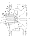
図9は、本発明に係る過給機の一例として、電動アシスト過給機の概略構成例を示す縦断面図である。図示の電動アシスト過給機(以下、「過給機」と呼ぶ)10は、例えば図示しない舶用ディーゼル機関(例えば、低速2サイクルディーゼル機関)に備えられて、舶用ディーゼル機関を構成するシリンダライナ(図示せず)の内部と連通する給気マニホールド(図示せず)に、圧縮された空気を供給する装置である。
DESCRIPTION OF EMBODIMENTS Hereinafter, an embodiment of a supercharger manufacturing method and a supercharger according to the present invention will be described with reference to the drawings.
FIG. 9 is a longitudinal sectional view showing a schematic configuration example of an electric assist supercharger as an example of the supercharger according to the present invention. The illustrated electric assist supercharger (hereinafter referred to as “supercharger”) 10 is provided, for example, in a marine diesel engine (not shown) (for example, a low speed two-cycle diesel engine), and a cylinder liner ( This is a device for supplying compressed air to an air supply manifold (not shown) communicating with the inside of the air (not shown).
図9に示すように、本実施形態の過給機10は、ガス入口ケーシング11、ガス出口ケーシング12、軸受台13及びコンプレッサ側の空気案内ケーシング14がボルト(図示せず)によって一体に締結されることにより構成されている。ロータ軸15は、軸受台13内に設けたスラスト軸受16及びラジアル軸受17、18により回転自在に支持されており、一端部にタービン部を構成するタービン19を有し、他端部にコンプレッサ部を構成するコンプレッサ羽根車(羽根車)20を有している。
As shown in FIG. 9, in the
タービン19は、外周部に多数のブレード19aを有している。このブレード19aは、ガス入口ケーシング11に設けられた排気ガス導入路22と、ガス出口ケーシング12に設けられた排気ガス排出路23との間に配置されている。
一方、コンプレッサ羽根車20は、外周部に多数のブレード20aを有している。このブレード20aは、空気案内ケーシング14に設けられた吸入空気導入路(吸気流路)24の下流側に配置されている。吸入空気導入路24は、コンプレッサ羽根車20を介して渦室25に接続され、さらに、渦室25は図示しない吸入空気導入路を介してエンジンの燃焼室に接続されている。
The
On the other hand, the
また、上述した過給機10は、吸入空気導入路24の上流側にサイレンサ26を備えている。このサイレンサ26は、コンプレッサ部で圧縮する吸入空気が吸入空気導入路24に吸入される前段(上流側)に、すなわち吸入空気導入路24の入口部上流側に設置され、吸入空気を通過させることで空気流を整流するフィルタ機能と、空気吸入によって発生する騒音を吸収する消音機能とを有している。このサイレンサ26は、中間ピース27を介して空気案内ケーシング14に支持されている。
The
そして、本実施形態の過給機10は、ロータ軸15に接続したモータ30を備えている。このモータ30は、ハイブリッド過給機に用いられていた電動発電機の発電機能を省略し、電動機能に絞ることで小型化したものである。このため、モータ30は、ロータ軸15を吸入空気導入路24側へ延長して取り付ける構造、すなわち、モータ30が専用の軸受を持たないモータオーバハング構造となる。従って、モータ30及び後述するモータ30のモータロータ31は、ロータ軸15を支持するスラスト軸受16及びラジアル軸受17、18により支持された構造となる。
The
図10は、上述したモータ30の周辺部を拡大した図である。
このモータ30は、モータロータ31、ステータ32及びハウジング33を主な構成要素とする。このうち、モータロータ31は、外周面に永久磁石を備える円柱形状の部材であり、その一端部がロータ軸15の端部とフランジ結合により接続されている。このフランジ結合は、ロータ軸15の吸入空気導入路24側となる端部に設けたフランジ31aと、モータロータ31のコンプレッサ羽根車20側となる端部に設けたフランジ15aとを接合し、複数のボルト・ナット34を用いて連結したものである。
FIG. 10 is an enlarged view of the periphery of the
The
ステータ32は、円筒形状のハウジング33内に収納設置されている。このハウジング33は、図9に示すように、サポート部材35を介して空気案内ケーシング14に支持されている。なお、サポート部材35と空気案内ケーシング14との間及びサポート部材35とハウジング33との間は、各々六角ボルト36によって連結されている。
The
ステータ32の中空部には、軸中心部を通るモータロータ31が非接触の状態で配設されている。
また、ハウジング33の吸入空気導入路24側となる端部には、キャップ37が六角穴付ボルト38により固定して取り付けられている。このキャップ37は、サイレンサ26よりコンプレッサ羽根車20側に位置している。すなわち、モータ30は、ロータ軸15の軸延長部がサイレンサ26に到達しない大きさまで小型化されている。
In the hollow portion of the
A
以下では、上述した構成の過給機10にモータ30を組み付ける製造手順(組立方法)について、図1から図8を参照して説明する。
図1は、モータ組立の第1工程として、モータロータ31をロータ軸15に接続して取り付けるロータ取付工程を示す要部断面図である。この第1工程では、コンプレッサ羽根車20の組み付けが完了した後、ロータ軸15の端部に対してモータロータ31をフランジ結合により接続させるとともに、モータロータ31の外周側に保護筒40を装着させる作業が実施される。なお、第1工程の開始時においては、モータロータ31をフランジ結合させる際の作業性を確保するため、空気案内ケーシング14が取り付けられていない状態としてもよい。
Hereinafter, a manufacturing procedure (assembly method) for assembling the
FIG. 1 is a cross-sectional view of an essential part showing a rotor mounting process in which a
ロータ軸15とモータロータ31とのフランジ結合は、互いのフランジ15a,31aを所定の状態に接合した後、複数のボルト・ナット34を用いて連結するものである。
こうしてロータ軸15にモータロータ31が接続された後には、後工程の作業を容易にするため、ロータモータ31に保護筒40が装着される。この保護筒40は、易滑性を有するとともに磁性のない材料が望ましく、ナイロンやポリエチレンなどプラスッチック系材料を利用できる。好適な材料の一例として、例えばMC901(製品名)相当のナイロン(ポリアミド樹脂)を用いることができる。さらに、保護筒40は、モータロータ31を完全に収容するとともに、後述する第2工程において所定位置に組み付けられるハウジング33のサイレンサ26側の端部よりもサイレンサ26の方向へ突出する長さを有している。
In the flange connection between the
After the
また、保護筒40の外側には、作業中に起こりうる工具やボルトがモータロータ磁石部に引き付けられ接触した際にモータロータを保護するため、例えばナイロン等の帯状部材41を巻き付けておくことが望ましい。
なお、ロータ軸15にモータロータ31を接続させた後に、空気案内ケーシング14を所定位置に固定設置することとしてもよい。
In addition, a belt-
The
図2は、モータ組立の第2工程として、ハウジング33をロータ軸15と同心に固定支持させるハウジング取付工程を示す図であり、図2(a)はサイレンサ26を取り付ける方向から見た要部の側面図(図2(b)の左側面図)、図2(b)はモータ周辺の要部断面図である。この第2工程は、ステータ32を組み付けする前の段階であり、ハウジング33とサポート部材35とを連結して一体化したステータ・サポートユニットHSを、ロータ軸15の軸心と同心となるように空気案内ケーシング14の所定位置に取り付ける。
FIG. 2 is a diagram showing a housing mounting step for fixing and supporting the
サポート部材35は、リング状のフランジ部35aと、複数(本実施形態では4本)の連結バー35bとを具備して構成される。フランジ部35aは、空気案内ケーシング14に六角ボルト36で固定される部分であり、複数(本実施形態では6個)のボルト穴35cが円周方向に等ピッチで設けられている。
連結バー35bは、フランジ部35aとハウジング33の外周部とを連結する部材であり、ハウジング33をフランジ部35aの軸中心位置に保持する機能を有している。
The
The connecting
図3は、ハウジング33を示す断面図である。ハウジング33は、円筒形状の部材であり、外周面には連結バー35bの一端部側を固定するボルト穴33aを備えた台座33bと、放熱フィン33cとが設けられている。
一方、ハウジング33の内壁面には、全周にわたる凹溝部33dが軸方向に複数(本実施形態では7列)設けられている。さらに、この凹溝部33dには、ステータ32を組み込む際に凹溝部33dの角部に衝突することを防止するため、軸方向両端部の角部を面取りするようにして傾斜面33eが設けられている。
FIG. 3 is a cross-sectional view showing the
On the other hand, the inner wall surface of the
上述した凹溝部33dを設けたことにより、後述するステータ32を挿入して組み込む際には、ステータ32と接触する内壁面の面積が減少するので、摩擦力の低減により挿入が容易になる。
そして、モータ組立の第2工程では、ハウジング33の内壁面に、すなわち、ハウジング33の凹溝部33dを含む内壁面の全面に放熱グリースを薄く塗布しておく。この放熱グリースは、運転時の放熱性向上に貢献するとともに、ステータ32を組み込む工程においては、滑りをよくしてスムーズな挿入にも貢献する。なお、図中の符号33fは、過剰な放熱グリースを押し出して排出するためのグリース排出口である。
By providing the above-described
Then, in the second step of motor assembly, the heat dissipating grease is thinly applied to the inner wall surface of the
このように構成されたステータ・サポートユニットHSを空気案内ケーシング14に取り付ける際には、モータロータ31の強力な永久磁石に金属部材が引き寄せられて、くっ付いて固着化したり破損することが懸念される。このため、例えば図4に示すように、位置決め及びスライド用ガイドの機能を有する治具として、ガイドバー50を使用する。すなわち、ハウジング取付工程では、ハウジング33の位置決め及びスライドに複数のガイドバー50が用いられる。
ガイドバー50は、フランジ部35aを空気案内ケーシング14に固定する六角ボルト36と同径のネジ部51を一端に有する棒状部材であり、六角ボルト36を捩じ込む空気案内ケーシング14のボルト穴14aにネジ部51を捩じ込んで使用される。なお、このガイドバー50は、空気案内ケーシング14に取り付けた状態において、ネジ部51と反対側の先端部がモータロータ31の永久磁石から磁力の影響を受けないようにするため、十分な長さを有している。
When the stator / support unit HS configured as described above is attached to the
The
ガイドバー50を用いたステータ・サポートユニットHSの組み付けは、最初の準備段階として複数本のガイドバー50をボルト穴14aに捩じ込んで取り付ける。この場合、例えば上下2か所のボルト穴14aを利用して2本のガイドバー50を取り付ければ、ステータ・サポートユニットHSの安定した位置決め及びスライドが可能となるが、3本またはそれ以上のガイドバー50を使用すればより一層安定する。
ガイドバー50の設置完了後は、ステータ・サポートユニットHSの適所に設けたアイボルト(不図示)等を利用してステータ・サポートユニットHSを吊り上げ、フランジ部35aのボルト穴35cにガイドバー50の先端部を挿入して位置決めする。この後、ステータ・サポートユニットHSをガイドバー50に沿ってスライドさせ、空気案内ケーシング14の設置面まで移動させる。このとき、ステータ・サポートユニットHSは、モータロータ31に接近して磁力を受けるが、ガイドバー50に保持されているため引き寄せられることはない。
Assembling of the stator support unit HS using the
After the installation of the
こうして所定の取付位置に移動したステータ・サポートユニットHSは、ガイドバー50が捩じ込まれていないボルト穴35c,14aに順次六角ボルト36を捩じ込むことで仮止めされる。この後、ガイドバー50を取り外し、六角ボルト36をボルト穴35c,14aに捩じ込むとともに、全ての六角ボルト36を所定量締めこむことで、ステータ・サポートユニットHSの固定が完了する。この結果、ステータ・サポートユニットHSは、フランジ部35aの中心及びハウジング33がロータ軸15の軸心と一致した位置に保持される。
The stator / support unit HS thus moved to the predetermined mounting position is temporarily fixed by sequentially screwing the
図5は、モータ組立の第3工程として、ハウジング33をガイドにしてステータ32を挿入して組み込むステータ取付工程を示す要部断面図である。この第3工程では、最初に保護筒40の外周に巻き付けた帯状部材41がステータに干渉しないよう、帯状部材41を取り除く。
この後、ロータ軸15の軸心と同心のハウジング33をガイドにして、ステータ32をハウジング33の内部へ滑り込ませるようにして組み込む。すなわち、ハウジング33の内径及びステータ32の外径は略一致しているので、ステータ32が半径方向に位置ずれすることなくハウジング33の内面に導かれて挿入される。このとき、ハウジング33の内面には放熱グリースが塗布され、さらに、摩擦力を低減する凹溝部33dが設けられているので、滑りがよくなりスムーズな挿入が可能となる。
FIG. 5 is a cross-sectional view of a main part showing a stator mounting step in which the
Thereafter, the
また、モータロータ31には保護筒40が装着されているので、挿入されるステータ32とモータロータ31とが接触することはない。仮にステータ32がモータロータ31に引き寄せられた場合でも、保護筒40の存在により接触時の衝撃からモータロータ31を保護できて破損を防止し、さらに、ステータ32とモータロータ31と保護筒40の板厚で離れているので、くっついたモータロータ31は固着には至らずに剥がしやすくなる。
こうしてステータ32をハウジング33内の所定位置に組み込んだ後には、モータロータ31の外周から保護筒40を引き抜いて取り外す。なお、モータ30には、モータロータ31の外周面とステータ32の内周面との間に所定の隙間が設けられているので、保護筒40の肉厚を隙間以下にすることで、ステータ32を組み付けた後でも容易に抜き出すことが可能である。
Further, since the
Thus, after the
図6は、モータ組立の第4工程を示す要部断面図である。この第4工程では、ステータ32を挿入したハウジング33の先端部にキャップ37を取り付けて六角穴付ボルト38で固定する。この結果、ステータ32はハウジング33内の所定位置に保持され、モータ30の組み付けは完了する。
また、メンテナンスのためにハウジング33の取り外し工程が発生した場合には、この逆の動作手順で、ステータ32とモータロータ31を安全に簡易に取り外すことが可能となる。
この後、図7及び図8に示すように、サイレンサ26の取り付けが行われる。図7では、サイレンサ26を取り付ける中間ピース27が空気案内ケーシング14に取り付けられ、さらに、図8では、中間ピース27にサイレンサ26が取り付けられる。なお、サイレンサ26を中間ピース27に取り付ける前には、モータ30側の付属の配線を束ね、所定の配線通路に入れ込んでおく。
FIG. 6 is a fragmentary cross-sectional view showing a fourth step of motor assembly. In this fourth step, a
Further, when the
Thereafter, as shown in FIGS. 7 and 8, the
上述した本実施形態によれば、モータオーバハング構造を採用している過給機10においては、モータロータ31及びステータ32を順次組み付けるモータ30の組立時に、永久磁石によってステータ32等の金属部品が引き寄せられることを防止でき、この結果、ロータ軸15に対するモータ30の組付作業が容易になる。
そして、このようなモータオーバハング構造を採用した過給機10のモータ30は、潤滑油による潤滑を必要とする軸受が不要であり、従って、潤滑油も不要となるため、既存過給機へのレトロフィットが容易になるとともに、低コスト化も容易になる。
なお、本発明は上述した実施形態に限定されることはなく、その要旨を逸脱しない範囲内において適宜変更することができる。
According to the above-described embodiment, in the
Further, the
In addition, this invention is not limited to embodiment mentioned above, In the range which does not deviate from the summary, it can change suitably.
10 電動アシスト過給機(過給機)
11 ガス入口ケーシング
12 ガス出口ケーシング
13 軸受台
14 空気案内ケーシング
15 ロータ軸
19 タービン
20 コンプレッサ羽根車
22 排気ガス導入路
23 排気ガス排出路
24 吸入空気導入路
25 渦室
26 サイレンサ
30 モータ
31 モータロータ
32 ステータ
33 ハウジング
35 サポート部材
36 六角ボルト
37 キャップ
40 保護筒
41 帯状部材
50 ガイドバー
HS ステータ・サポートユニット
10 Electric assist supercharger (supercharger)
DESCRIPTION OF
Claims (7)
前記モータが、円筒形状のハウジングと、該ハウジングの内部に収納されているステータと、前記ロータ軸の端部に接続されて前記ステータの内部で回転する永久磁石を備えたモータロータとを具備し、
前記モータロータを前記ロータ軸に接続して取り付けるロータ取付工程と、
前記ハウジングを前記ロータ軸と同心に固定支持させるハウジング取付工程と、
前記ハウジングをガイドにして前記ハウジングの内部に前記ステータを前記モータロータと直接に接触しないように挿入して組み込むステータ取付工程と、
を備えていることを特徴とする過給機の製造方法。 A method of manufacturing a supercharger in which a motor is attached to an end of a rotor shaft connected to a compressor unit,
The motor includes a cylindrical housing, a stator housed in the housing, and a motor rotor provided with a permanent magnet connected to an end of the rotor shaft and rotating inside the stator,
A rotor mounting step of connecting and mounting the motor rotor to the rotor shaft;
A housing mounting step for fixing and supporting the housing concentrically with the rotor shaft;
A stator mounting step in which the housing is inserted into the housing so as not to be in direct contact with the motor rotor, and the stator is mounted in the housing.
A method for manufacturing a supercharger, comprising:
Priority Applications (6)
| Application Number | Priority Date | Filing Date | Title |
|---|---|---|---|
| JP2014042073A JP5894203B2 (en) | 2014-03-04 | 2014-03-04 | Supercharger manufacturing method |
| KR1020157026692A KR101644287B1 (en) | 2014-03-04 | 2015-02-23 | Supercharger manufacturing method and supercharger |
| US14/787,658 US10180143B2 (en) | 2014-03-04 | 2015-02-23 | Method of manufacturing turbocharger and turbocharger |
| CN201580000467.9A CN105074160B (en) | 2014-03-04 | 2015-02-23 | The manufacture method of supercharger and supercharger |
| PCT/JP2015/054930 WO2015133303A1 (en) | 2014-03-04 | 2015-02-23 | Supercharger manufacturing method and supercharger |
| EP15759319.5A EP2977588A4 (en) | 2014-03-04 | 2015-02-23 | Supercharger manufacturing method and supercharger |
Applications Claiming Priority (1)
| Application Number | Priority Date | Filing Date | Title |
|---|---|---|---|
| JP2014042073A JP5894203B2 (en) | 2014-03-04 | 2014-03-04 | Supercharger manufacturing method |
Publications (2)
| Publication Number | Publication Date |
|---|---|
| JP2015169073A JP2015169073A (en) | 2015-09-28 |
| JP5894203B2 true JP5894203B2 (en) | 2016-03-23 |
Family
ID=54055113
Family Applications (1)
| Application Number | Title | Priority Date | Filing Date |
|---|---|---|---|
| JP2014042073A Active JP5894203B2 (en) | 2014-03-04 | 2014-03-04 | Supercharger manufacturing method |
Country Status (6)
| Country | Link |
|---|---|
| US (1) | US10180143B2 (en) |
| EP (1) | EP2977588A4 (en) |
| JP (1) | JP5894203B2 (en) |
| KR (1) | KR101644287B1 (en) |
| CN (1) | CN105074160B (en) |
| WO (1) | WO2015133303A1 (en) |
Cited By (1)
| Publication number | Priority date | Publication date | Assignee | Title |
|---|---|---|---|---|
| US10704556B2 (en) | 2017-08-30 | 2020-07-07 | Mitsubishi Heavy Industries, Ltd. | Motor, turbocharger and assembly method turbocharger |
Families Citing this family (12)
| Publication number | Priority date | Publication date | Assignee | Title |
|---|---|---|---|---|
| JP5894203B2 (en) | 2014-03-04 | 2016-03-23 | 三菱重工業株式会社 | Supercharger manufacturing method |
| DE102016100819A1 (en) * | 2015-02-20 | 2016-08-25 | Abb Turbo Systems Ag | coupling device |
| JP6589217B2 (en) * | 2015-04-17 | 2019-10-16 | 三菱重工コンプレッサ株式会社 | Rotating machine, method of manufacturing rotating machine |
| JP6563321B2 (en) * | 2015-12-03 | 2019-08-21 | 三菱重工業株式会社 | Electric motor support mechanism, compressor, and supercharger |
| US10077785B2 (en) * | 2016-04-21 | 2018-09-18 | Mitsubishi Heavy Industries, Ltd. | Impeller assembly, turbocharger, and method of assembling impeller assembly |
| DE202016102995U1 (en) * | 2016-06-06 | 2017-09-07 | Max Baermann Gmbh | Magnetic rotating member |
| FR3055754B1 (en) * | 2016-09-02 | 2018-09-07 | Danfoss A/S | ROTOR FOR A HIGH SPEED ELECTRIC MOTOR |
| DE102016221639B4 (en) * | 2016-11-04 | 2021-11-25 | Ford Global Technologies, Llc | Supercharged internal combustion engine with a cooled compressor |
| CN106451946B (en) * | 2016-12-22 | 2023-05-02 | 珠海精实测控技术股份有限公司 | Rotor assembly all-in-one |
| DE102018216080A1 (en) * | 2018-09-20 | 2020-03-26 | Robert Bosch Gmbh | Electric drive machine for a compressor and / or a turbine, turbocharger and / or turbine |
| FR3092448B1 (en) * | 2019-02-04 | 2021-01-15 | Ifp Energies Now | Device for compressing a fluid driven by an electric machine with a rotor equipped with a solid cylindrical magnet |
| JP2021013223A (en) * | 2019-07-04 | 2021-02-04 | 本田技研工業株式会社 | Rotary electric machine assembly device and rotary electric machine assembly method |
Family Cites Families (35)
| Publication number | Priority date | Publication date | Assignee | Title |
|---|---|---|---|---|
| CA701612A (en) * | 1958-11-04 | 1965-01-12 | W. Wightman Lawrance | Dynamoelectric machines and methods of manufacture for same |
| US3268986A (en) * | 1963-05-07 | 1966-08-30 | Gen Electric | Method of manufacturing dynamo-electric machines |
| GB1192792A (en) * | 1967-05-18 | 1970-05-20 | Ranco Motors Ltd | A method of Electric Motor Assembly |
| US5767596A (en) * | 1996-10-03 | 1998-06-16 | General Electric Company | Dynamoelectric machine and processes for making the same |
| US6321439B1 (en) * | 1997-01-21 | 2001-11-27 | Siemens Westinghouse Power Corporation | Method for assembly of a stator in the field |
| US6305169B1 (en) * | 1999-02-22 | 2001-10-23 | Ralph P. Mallof | Motor assisted turbocharger |
| GB2354553B (en) * | 1999-09-23 | 2004-02-04 | Turbo Genset Company Ltd The | Electric turbocharging system |
| US6739845B2 (en) * | 2002-05-30 | 2004-05-25 | William E. Woollenweber | Compact turbocharger |
| US7025579B2 (en) * | 2001-10-16 | 2006-04-11 | Innovative Turbo Systems Corporation | Bearing system for high-speed rotating machinery |
| JP2004023901A (en) | 2002-06-17 | 2004-01-22 | Minebea Co Ltd | Rotor of motor and manufacturing method therefor |
| JP4426259B2 (en) * | 2003-11-19 | 2010-03-03 | 株式会社日立製作所 | Gas turbine equipment and gas turbine power generation equipment |
| US7353586B2 (en) * | 2004-04-26 | 2008-04-08 | Siemens Power Generation, Inc. | Method of horizontally stacking a stator core within a stator frame |
| US7653986B2 (en) * | 2004-04-26 | 2010-02-02 | Siemens Energy, Inc. | Horizontal assembly of stator core using keybar extensions |
| DE102004029828A1 (en) | 2004-06-19 | 2006-01-19 | Daimlerchrysler Ag | Exhaust gas turbocharger for an internal combustion engine and method for operating an Agbasturbolader |
| JP4591828B2 (en) * | 2005-08-22 | 2010-12-01 | 株式会社Ihi | Supercharger with electric motor |
| JP4247217B2 (en) * | 2005-08-25 | 2009-04-02 | 三菱重工業株式会社 | Exhaust turbine turbocharger |
| CN101573516B (en) * | 2007-02-09 | 2011-06-15 | 三菱重工业株式会社 | Exhaust gas turbocharger |
| JP4648347B2 (en) * | 2007-02-23 | 2011-03-09 | 三菱重工業株式会社 | Hybrid exhaust turbine turbocharger |
| JP4898491B2 (en) * | 2007-02-23 | 2012-03-14 | 三菱重工業株式会社 | Power turbine test equipment |
| DE102007062540A1 (en) * | 2007-12-20 | 2009-06-25 | Sycotec Gmbh & Co. Kg | Electric motor or generator |
| FI122036B (en) * | 2008-01-10 | 2011-07-29 | Waertsilae Finland Oy | Piston engine turbocharger arrangement |
| FI121800B (en) * | 2008-01-10 | 2011-04-15 | Waertsilae Finland Oy | Piston engine supercharging |
| US7699097B2 (en) | 2008-06-11 | 2010-04-20 | Digitek Technology Co., Ltd. | Mover stabilizing and stator cooling arrangement of a 3-phase linear motor of a submersible oil pump |
| US20110025144A1 (en) * | 2009-07-28 | 2011-02-03 | Caterpillar, Inc. | Cooling housing for a switched reluctance electric device |
| EP2385614B1 (en) | 2010-05-06 | 2013-03-27 | The Switch Drive Systems Oy | An electrical machine and a method for assembling it |
| JP5529714B2 (en) * | 2010-11-12 | 2014-06-25 | 三菱重工業株式会社 | Electric supercharger rotating shaft support structure |
| JP2012177330A (en) * | 2011-02-25 | 2012-09-13 | Mitsubishi Heavy Ind Ltd | Hybrid supercharger |
| JP2012197684A (en) * | 2011-03-18 | 2012-10-18 | Mitsubishi Heavy Ind Ltd | Single-shaft two-stage supercharger |
| JP2012229676A (en) * | 2011-04-27 | 2012-11-22 | Ihi Corp | Attachment structure of heat shield plate and supercharger |
| JP5535992B2 (en) * | 2011-07-15 | 2014-07-02 | 三菱重工業株式会社 | Electric supercharged compressor, its assembly method and internal combustion engine |
| GB2497113B (en) | 2011-12-01 | 2017-03-01 | Cummins Ltd | Turbocharger arrangement including a generator |
| TWI472129B (en) * | 2012-11-21 | 2015-02-01 | Ind Tech Res Inst | Stator structure |
| US20140190001A1 (en) * | 2013-01-04 | 2014-07-10 | Michael P. Jaszcar | Rail system for installing a stator core in a frame |
| JP5863720B2 (en) | 2013-07-10 | 2016-02-17 | 三菱重工業株式会社 | Silencer for turbocharger |
| JP5894203B2 (en) | 2014-03-04 | 2016-03-23 | 三菱重工業株式会社 | Supercharger manufacturing method |
-
2014
- 2014-03-04 JP JP2014042073A patent/JP5894203B2/en active Active
-
2015
- 2015-02-23 US US14/787,658 patent/US10180143B2/en active Active
- 2015-02-23 CN CN201580000467.9A patent/CN105074160B/en active Active
- 2015-02-23 EP EP15759319.5A patent/EP2977588A4/en not_active Withdrawn
- 2015-02-23 KR KR1020157026692A patent/KR101644287B1/en active IP Right Grant
- 2015-02-23 WO PCT/JP2015/054930 patent/WO2015133303A1/en active Application Filing
Cited By (1)
| Publication number | Priority date | Publication date | Assignee | Title |
|---|---|---|---|---|
| US10704556B2 (en) | 2017-08-30 | 2020-07-07 | Mitsubishi Heavy Industries, Ltd. | Motor, turbocharger and assembly method turbocharger |
Also Published As
| Publication number | Publication date |
|---|---|
| EP2977588A1 (en) | 2016-01-27 |
| CN105074160B (en) | 2016-12-21 |
| EP2977588A4 (en) | 2016-07-20 |
| KR20150119465A (en) | 2015-10-23 |
| CN105074160A (en) | 2015-11-18 |
| JP2015169073A (en) | 2015-09-28 |
| US10180143B2 (en) | 2019-01-15 |
| KR101644287B1 (en) | 2016-07-29 |
| US20160369817A1 (en) | 2016-12-22 |
| WO2015133303A1 (en) | 2015-09-11 |
Similar Documents
| Publication | Publication Date | Title |
|---|---|---|
| JP5894203B2 (en) | Supercharger manufacturing method | |
| US11396889B2 (en) | Supercharger and motor cooling method | |
| US8096126B2 (en) | Motor-driven supercharger | |
| US8096127B2 (en) | Exhaust turbo-supercharger | |
| US8174141B2 (en) | Turbo generator | |
| US20110239660A1 (en) | Mounting arrangement for gas turbine engine accessories and gearbox therefor | |
| KR101536549B1 (en) | Hybrid exhaust turbine supercharger | |
| EP2229515A2 (en) | Turbocharger arrangement for a piston engine | |
| CN104246143A (en) | Power transmission system for a turbomachine | |
| EP3173630B1 (en) | Compressor and turbocharger | |
| WO2017183544A1 (en) | Impeller assembly, supercharger, and method for assembling impeller assembly | |
| JP7305314B2 (en) | Motor, supercharger and method of assembling supercharger | |
| JP2013142359A (en) | Impeller mounting device | |
| WO2019117045A1 (en) | Supercharger | |
| CN214661568U (en) | Pressure end full floating bearing | |
| US10837363B2 (en) | Systems for an electric turbocharger |
Legal Events
| Date | Code | Title | Description |
|---|---|---|---|
| A621 | Written request for application examination |
Free format text: JAPANESE INTERMEDIATE CODE: A621 Effective date: 20150625 |
|
| A871 | Explanation of circumstances concerning accelerated examination |
Free format text: JAPANESE INTERMEDIATE CODE: A871 Effective date: 20150625 |
|
| A975 | Report on accelerated examination |
Free format text: JAPANESE INTERMEDIATE CODE: A971005 Effective date: 20150914 |
|
| A131 | Notification of reasons for refusal |
Free format text: JAPANESE INTERMEDIATE CODE: A131 Effective date: 20150929 |
|
| A521 | Written amendment |
Free format text: JAPANESE INTERMEDIATE CODE: A523 Effective date: 20151119 |
|
| TRDD | Decision of grant or rejection written | ||
| A01 | Written decision to grant a patent or to grant a registration (utility model) |
Free format text: JAPANESE INTERMEDIATE CODE: A01 Effective date: 20160126 |
|
| A61 | First payment of annual fees (during grant procedure) |
Free format text: JAPANESE INTERMEDIATE CODE: A61 Effective date: 20160225 |
|
| R151 | Written notification of patent or utility model registration |
Ref document number: 5894203 Country of ref document: JP Free format text: JAPANESE INTERMEDIATE CODE: R151 |
|
| S111 | Request for change of ownership or part of ownership |
Free format text: JAPANESE INTERMEDIATE CODE: R313113 |
|
| R350 | Written notification of registration of transfer |
Free format text: JAPANESE INTERMEDIATE CODE: R350 |