EP2977588A1 - Supercharger manufacturing method and supercharger - Google Patents
Supercharger manufacturing method and supercharger Download PDFInfo
- Publication number
- EP2977588A1 EP2977588A1 EP15759319.5A EP15759319A EP2977588A1 EP 2977588 A1 EP2977588 A1 EP 2977588A1 EP 15759319 A EP15759319 A EP 15759319A EP 2977588 A1 EP2977588 A1 EP 2977588A1
- Authority
- EP
- European Patent Office
- Prior art keywords
- housing
- motor
- stator
- rotor
- turbocharger
- Prior art date
- Legal status (The legal status is an assumption and is not a legal conclusion. Google has not performed a legal analysis and makes no representation as to the accuracy of the status listed.)
- Withdrawn
Links
Images


Classifications
-
- F—MECHANICAL ENGINEERING; LIGHTING; HEATING; WEAPONS; BLASTING
- F02—COMBUSTION ENGINES; HOT-GAS OR COMBUSTION-PRODUCT ENGINE PLANTS
- F02B—INTERNAL-COMBUSTION PISTON ENGINES; COMBUSTION ENGINES IN GENERAL
- F02B37/00—Engines characterised by provision of pumps driven at least for part of the time by exhaust
- F02B37/04—Engines with exhaust drive and other drive of pumps, e.g. with exhaust-driven pump and mechanically-driven second pump
- F02B37/10—Engines with exhaust drive and other drive of pumps, e.g. with exhaust-driven pump and mechanically-driven second pump at least one pump being alternatively or simultaneously driven by exhaust and other drive, e.g. by pressurised fluid from a reservoir or an engine-driven pump
-
- F—MECHANICAL ENGINEERING; LIGHTING; HEATING; WEAPONS; BLASTING
- F04—POSITIVE - DISPLACEMENT MACHINES FOR LIQUIDS; PUMPS FOR LIQUIDS OR ELASTIC FLUIDS
- F04D—NON-POSITIVE-DISPLACEMENT PUMPS
- F04D25/00—Pumping installations or systems
- F04D25/02—Units comprising pumps and their driving means
- F04D25/04—Units comprising pumps and their driving means the pump being fluid-driven
- F04D25/045—Units comprising pumps and their driving means the pump being fluid-driven the pump wheel carrying the fluid driving means, e.g. turbine blades
-
- F—MECHANICAL ENGINEERING; LIGHTING; HEATING; WEAPONS; BLASTING
- F01—MACHINES OR ENGINES IN GENERAL; ENGINE PLANTS IN GENERAL; STEAM ENGINES
- F01D—NON-POSITIVE DISPLACEMENT MACHINES OR ENGINES, e.g. STEAM TURBINES
- F01D15/00—Adaptations of machines or engines for special use; Combinations of engines with devices driven thereby
- F01D15/10—Adaptations for driving, or combinations with, electric generators
-
- F—MECHANICAL ENGINEERING; LIGHTING; HEATING; WEAPONS; BLASTING
- F02—COMBUSTION ENGINES; HOT-GAS OR COMBUSTION-PRODUCT ENGINE PLANTS
- F02B—INTERNAL-COMBUSTION PISTON ENGINES; COMBUSTION ENGINES IN GENERAL
- F02B39/00—Component parts, details, or accessories relating to, driven charging or scavenging pumps, not provided for in groups F02B33/00 - F02B37/00
- F02B39/02—Drives of pumps; Varying pump drive gear ratio
- F02B39/08—Non-mechanical drives, e.g. fluid drives having variable gear ratio
- F02B39/10—Non-mechanical drives, e.g. fluid drives having variable gear ratio electric
-
- F—MECHANICAL ENGINEERING; LIGHTING; HEATING; WEAPONS; BLASTING
- F04—POSITIVE - DISPLACEMENT MACHINES FOR LIQUIDS; PUMPS FOR LIQUIDS OR ELASTIC FLUIDS
- F04D—NON-POSITIVE-DISPLACEMENT PUMPS
- F04D17/00—Radial-flow pumps, e.g. centrifugal pumps; Helico-centrifugal pumps
- F04D17/08—Centrifugal pumps
- F04D17/10—Centrifugal pumps for compressing or evacuating
-
- F—MECHANICAL ENGINEERING; LIGHTING; HEATING; WEAPONS; BLASTING
- F04—POSITIVE - DISPLACEMENT MACHINES FOR LIQUIDS; PUMPS FOR LIQUIDS OR ELASTIC FLUIDS
- F04D—NON-POSITIVE-DISPLACEMENT PUMPS
- F04D25/00—Pumping installations or systems
- F04D25/02—Units comprising pumps and their driving means
- F04D25/024—Units comprising pumps and their driving means the driving means being assisted by a power recovery turbine
-
- F—MECHANICAL ENGINEERING; LIGHTING; HEATING; WEAPONS; BLASTING
- F04—POSITIVE - DISPLACEMENT MACHINES FOR LIQUIDS; PUMPS FOR LIQUIDS OR ELASTIC FLUIDS
- F04D—NON-POSITIVE-DISPLACEMENT PUMPS
- F04D25/00—Pumping installations or systems
- F04D25/02—Units comprising pumps and their driving means
- F04D25/06—Units comprising pumps and their driving means the pump being electrically driven
- F04D25/0606—Units comprising pumps and their driving means the pump being electrically driven the electric motor being specially adapted for integration in the pump
-
- F—MECHANICAL ENGINEERING; LIGHTING; HEATING; WEAPONS; BLASTING
- F04—POSITIVE - DISPLACEMENT MACHINES FOR LIQUIDS; PUMPS FOR LIQUIDS OR ELASTIC FLUIDS
- F04D—NON-POSITIVE-DISPLACEMENT PUMPS
- F04D29/00—Details, component parts, or accessories
- F04D29/18—Rotors
- F04D29/20—Mounting rotors on shafts
-
- F—MECHANICAL ENGINEERING; LIGHTING; HEATING; WEAPONS; BLASTING
- F04—POSITIVE - DISPLACEMENT MACHINES FOR LIQUIDS; PUMPS FOR LIQUIDS OR ELASTIC FLUIDS
- F04D—NON-POSITIVE-DISPLACEMENT PUMPS
- F04D29/00—Details, component parts, or accessories
- F04D29/26—Rotors specially for elastic fluids
- F04D29/266—Rotors specially for elastic fluids mounting compressor rotors on shafts
-
- F—MECHANICAL ENGINEERING; LIGHTING; HEATING; WEAPONS; BLASTING
- F04—POSITIVE - DISPLACEMENT MACHINES FOR LIQUIDS; PUMPS FOR LIQUIDS OR ELASTIC FLUIDS
- F04D—NON-POSITIVE-DISPLACEMENT PUMPS
- F04D29/00—Details, component parts, or accessories
- F04D29/60—Mounting; Assembling; Disassembling
- F04D29/62—Mounting; Assembling; Disassembling of radial or helico-centrifugal pumps
- F04D29/624—Mounting; Assembling; Disassembling of radial or helico-centrifugal pumps especially adapted for elastic fluid pumps
-
- H—ELECTRICITY
- H02—GENERATION; CONVERSION OR DISTRIBUTION OF ELECTRIC POWER
- H02K—DYNAMO-ELECTRIC MACHINES
- H02K1/00—Details of the magnetic circuit
- H02K1/06—Details of the magnetic circuit characterised by the shape, form or construction
- H02K1/12—Stationary parts of the magnetic circuit
- H02K1/18—Means for mounting or fastening magnetic stationary parts on to, or to, the stator structures
- H02K1/185—Means for mounting or fastening magnetic stationary parts on to, or to, the stator structures to outer stators
-
- H—ELECTRICITY
- H02—GENERATION; CONVERSION OR DISTRIBUTION OF ELECTRIC POWER
- H02K—DYNAMO-ELECTRIC MACHINES
- H02K15/00—Methods or apparatus specially adapted for manufacturing, assembling, maintaining or repairing of dynamo-electric machines
- H02K15/02—Methods or apparatus specially adapted for manufacturing, assembling, maintaining or repairing of dynamo-electric machines of stator or rotor bodies
- H02K15/03—Methods or apparatus specially adapted for manufacturing, assembling, maintaining or repairing of dynamo-electric machines of stator or rotor bodies having permanent magnets
-
- H—ELECTRICITY
- H02—GENERATION; CONVERSION OR DISTRIBUTION OF ELECTRIC POWER
- H02K—DYNAMO-ELECTRIC MACHINES
- H02K15/00—Methods or apparatus specially adapted for manufacturing, assembling, maintaining or repairing of dynamo-electric machines
- H02K15/16—Centering rotors within the stator; Balancing rotors
-
- H—ELECTRICITY
- H02—GENERATION; CONVERSION OR DISTRIBUTION OF ELECTRIC POWER
- H02K—DYNAMO-ELECTRIC MACHINES
- H02K7/00—Arrangements for handling mechanical energy structurally associated with dynamo-electric machines, e.g. structural association with mechanical driving motors or auxiliary dynamo-electric machines
- H02K7/14—Structural association with mechanical loads, e.g. with hand-held machine tools or fans
-
- F—MECHANICAL ENGINEERING; LIGHTING; HEATING; WEAPONS; BLASTING
- F05—INDEXING SCHEMES RELATING TO ENGINES OR PUMPS IN VARIOUS SUBCLASSES OF CLASSES F01-F04
- F05B—INDEXING SCHEME RELATING TO WIND, SPRING, WEIGHT, INERTIA OR LIKE MOTORS, TO MACHINES OR ENGINES FOR LIQUIDS COVERED BY SUBCLASSES F03B, F03D AND F03G
- F05B2220/00—Application
- F05B2220/40—Application in turbochargers
-
- F—MECHANICAL ENGINEERING; LIGHTING; HEATING; WEAPONS; BLASTING
- F05—INDEXING SCHEMES RELATING TO ENGINES OR PUMPS IN VARIOUS SUBCLASSES OF CLASSES F01-F04
- F05B—INDEXING SCHEME RELATING TO WIND, SPRING, WEIGHT, INERTIA OR LIKE MOTORS, TO MACHINES OR ENGINES FOR LIQUIDS COVERED BY SUBCLASSES F03B, F03D AND F03G
- F05B2230/00—Manufacture
- F05B2230/60—Assembly methods
-
- F—MECHANICAL ENGINEERING; LIGHTING; HEATING; WEAPONS; BLASTING
- F05—INDEXING SCHEMES RELATING TO ENGINES OR PUMPS IN VARIOUS SUBCLASSES OF CLASSES F01-F04
- F05B—INDEXING SCHEME RELATING TO WIND, SPRING, WEIGHT, INERTIA OR LIKE MOTORS, TO MACHINES OR ENGINES FOR LIQUIDS COVERED BY SUBCLASSES F03B, F03D AND F03G
- F05B2240/00—Components
- F05B2240/60—Shafts
-
- F—MECHANICAL ENGINEERING; LIGHTING; HEATING; WEAPONS; BLASTING
- F05—INDEXING SCHEMES RELATING TO ENGINES OR PUMPS IN VARIOUS SUBCLASSES OF CLASSES F01-F04
- F05D—INDEXING SCHEME FOR ASPECTS RELATING TO NON-POSITIVE-DISPLACEMENT MACHINES OR ENGINES, GAS-TURBINES OR JET-PROPULSION PLANTS
- F05D2220/00—Application
- F05D2220/40—Application in turbochargers
-
- F—MECHANICAL ENGINEERING; LIGHTING; HEATING; WEAPONS; BLASTING
- F05—INDEXING SCHEMES RELATING TO ENGINES OR PUMPS IN VARIOUS SUBCLASSES OF CLASSES F01-F04
- F05D—INDEXING SCHEME FOR ASPECTS RELATING TO NON-POSITIVE-DISPLACEMENT MACHINES OR ENGINES, GAS-TURBINES OR JET-PROPULSION PLANTS
- F05D2230/00—Manufacture
- F05D2230/60—Assembly methods
-
- Y—GENERAL TAGGING OF NEW TECHNOLOGICAL DEVELOPMENTS; GENERAL TAGGING OF CROSS-SECTIONAL TECHNOLOGIES SPANNING OVER SEVERAL SECTIONS OF THE IPC; TECHNICAL SUBJECTS COVERED BY FORMER USPC CROSS-REFERENCE ART COLLECTIONS [XRACs] AND DIGESTS
- Y02—TECHNOLOGIES OR APPLICATIONS FOR MITIGATION OR ADAPTATION AGAINST CLIMATE CHANGE
- Y02T—CLIMATE CHANGE MITIGATION TECHNOLOGIES RELATED TO TRANSPORTATION
- Y02T10/00—Road transport of goods or passengers
- Y02T10/10—Internal combustion engine [ICE] based vehicles
- Y02T10/12—Improving ICE efficiencies
Definitions
- the present invention relates to a method of manufacturing a turbocharger and a turbocharger.
- a turbocharger which compresses air of an internal combustion engine and feeds air having high density to a combustion chamber
- the turbocharger is widely used in a two-stroke low-speed engine such as a marine diesel engine or a diesel engine for generating power.
- a compressor which compresses combustion air and a turbine serving as a drive source of the compressor are coaxially connected to each other, and the compressor and the turbine are accommodated in a casing and are integrally rotated.
- the turbocharger turbine is driven by energy held in exhaust gas of an internal combustion engine.
- a hybrid turbocharger in which a high-speed motor generator is connected to a rotor shaft is known.
- the hybrid turbocharger can supply pressurized combustion air to an internal combustion engine and generate electricity using excess exhaust gas energy to supply power.
- the hybrid turbocharger has a size capable of approximately penetrating the silencer.
- an electric assist turbocharger in which a miniaturized motor is adopted instead of the motor generator of the above-described hybrid turbocharger and the motor is housed in the turbocharger.
- the miniaturized motor is attached to a shaft extension portion in which a rotor shaft extends in an inlet air passage side.
- a size of the motor is small, it is possible to sufficiently support a weight of the motor rotor by the existing bearings of the turbocharger. Accordingly, in general, a structure in which a dedicated bearing for a motor is not required, that is, a motor overhang structure which does not have a dedicated bearing for a motor is adopted.
- the motor is used to assist turbocharger's compression by consuming electricity to supply enough scavenging pressure to the main engine in place of an auxiliary blower.
- PTL 1 discloses an electric supercharging compressor including rolling bearings which are provided on both sides of an electric motor and support a rotary shaft, and an assembly method thereof.
- the motor of the above-described electric assist turbocharger adopts the motor overhang structure which does not have a bearing.
- the motor overhang structure since a motor rotor of a miniaturized motor is attached to an extension portion of a rotor shaft, it is not necessary to install a dedicated bearing on the motor rotor, and the motor rotor is supported by bearings (bearing of the rotor shaft) supported by a turbocharger main body.
- the present invention is made to solve the above-described problems, and an object thereof is to provide a method of manufacturing a turbocharger capable of easily performing an operation of sequentially assembling a motor rotor and a stator in a turbocharger in which a motor overhang structure is adopted, and a turbocharger which is assembled according to the method of manufacturing.
- the present invention adopts the following means in order to solve the above-described problems.
- a method of manufacturing a turbocharger in which a motor is attached to an end portion of a rotor shaft connected to a compressor portion, the motor including a cylindrical housing, a stator accommodated inside the housing, and a motor rotor which is connected to an end portion of the rotor shaft and includes a permanent magnet rotating inside the stator, the method including: a rotor installation step of connecting and attaching the motor rotor to the rotor shaft; a housing installation step of coaxially fixing and supporting the housing to the rotor shaft; and a stator installation step of guiding the housing, and inserting the stator into the housing such that the stator does not directly come into contact with the motor rotor to incorporate the stator into the housing.
- the rotor installation step of connecting and attaching the motor rotor to the rotor shaft since the rotor installation step of connecting and attaching the motor rotor to the rotor shaft, the housing installation step of coaxially fixing and supporting the housing to the rotor shaft, and the stator installation step of guiding the housing, and inserting the stator into the housing such that the stator does not directly come into contact with the motor rotor to incorporate the stator into the housing are provided, when the stator is inserted into the housing, the stator having approximately the same diameter as the cylindrical housing is inserted into the housing along an inner wall surface of the cylindrical housing. Accordingly, it is possible to prevent the stator from being pulled toward the permanent magnet of the motor rotor, coming into contact with the permanent magnet, and becoming fixed to the permanent magnet.
- a protection tube is provided on the motor rotor. Accordingly, in the housing installation step or the stator installation step, it is possible to prevent the housing, the stator, or the like from coming into contact with the motor rotor.
- the protection tube is formed of a material such as nylon which has a sliding property and does not have magnetism.
- a step of providing a concave groove portion on an inner circumferential surface of the housing is provided. Accordingly, a contact area between the inserted stator and the inner circumferential surface of the housing is decreased, and it is possible to reduce a generated friction force.
- a step of chamfering corner portions of both end portions in an axial direction of the concave groove portion is provided. Accordingly, it is possible to smoothly insert the stator.
- a step of applying thermal grease for improving a heat transfer property to an inner wall surface of the housing is provided. Accordingly, heat transfer during an operation increases, and insertion of the stator becomes smoother.
- grease discharging ports which extrude excess thermal grease are provided in the housing.
- multiple guide bars are used to position and slide the housing.
- the guide bars it is possible to prevent a metal member such as a housing from being pulled toward a strong permanent magnet of the motor rotor, being fixed to the permanent magnet, and being damaged.
- a turbocharger including a motor which is attached according to the above-described method of manufacturing a turbocharger.
- turbocharger of the second aspect since the motor attached according to the above-described method of manufacturing a turbocharger is provided, it is possible to easily manufacture the turbocharger without a metal member being pulled toward the motor rotor having a strong permanent magnet due to a magnetic force of the motor rotor.
- a turbocharger which adopts a motor overhang structure
- a metal component such as a stator
- a strong permanent magnet being fixed to the permanent magnet
- a motor rotor and a stator are sequentially assembled to manufacture a motor
- an easy assembly operation of a motor becomes possible.
- a bearing which requires lubrication such as circulation of lubricating oil, is not needed, it is possible to easily perform retrofitting to the existing turbocharger and effectively reduce a cost.
- Fig. 9 is a vertical sectional view showing a schematic configuration example of an electric assist turbocharger as an example of the turbocharger according to the present invention.
- an electric assist turbocharger (hereinafter, referred to as a "turbocharger") 10 shown in Fig. 9 is provided in a marine diesel engine (not shown) (for example, a low-speed two cycle diesel engine), and is a device which supplies compressed air to an air supply manifold (not shown) which communicates with an inner portion of a cylinder liner (not shown) configuring a marine diesel engine.
- the turbocharger 10 of the present embodiment is configured by integrally connecting a gas inlet casing 11, a gas outlet casing 12, a bearing pedestal 13, and an air guide casing 14 of a compressor side by bolts (not shown).
- a rotor shaft 15 is rotatably supported by a thrust bearing 16 and journal bearings 17 and 18 which are provided inside the bearing pedestal 13, and includes a turbine 19 configuring a turbine portion on one end portion and a compressor impeller (impeller) 20 configuring a compressor portion on the other end.
- the turbine 19 includes multiple blades 19a on an outer circumferential portion of the turbine.
- the blades 19a are disposed between an exhaust gas introduction passage 22 which is provided in the gas inlet casing 11, and a exhaust gas discharge passage 23 which is provided in the gas outlet casing 12.
- the compressor impeller 20 includes multiple blades 20a on an outer circumferential portion of the compressor impeller.
- the blades 20a are disposed on a downstream side of an inlet air passage (intake channel) 24 provided in the air guide casing 14.
- the inlet air passage 24 is connected to a scroll chamber 25 via a compressor impeller 20, and the scroll chamber 25 is connected to a combustion chamber of an engine via an inlet air passage (not shown).
- the above-described turbocharger 10 includes a silencer 26 on the upstream side of the inlet air passage 24.
- the silencer 26 is installed in upstream of the inlet air passage 24, that is, air passes through the silencer 26 before the inlet air passage 24 and air compression. It works as a filter by straightening the passing air and a noise absorber.
- the silencer 26 is supported by the air guide casing 14 via an intermediate piece 27.
- the turbocharger 10 of the present embodiment includes a motor 30 which is connected to the rotor shaft 15.
- a power generation function of a motor generator which is used in a hybrid turbocharger is omitted, and only an electric motoring function is performed. Accordingly, the motor 30 is miniaturized. Therefore, the motor 30 has a structure in which the rotor shaft 15 extends to the inlet air passage 24 side so as to attach the motor, that is, has a motor overhang structure in which the motor 30 does not have a dedicated bearing. Accordingly, the motor 30 and the motor rotor 31 described below of the motor 30 are supported by the thrust bearing 16 and the journal bearings 17 and 18 which support the rotor shaft 15.
- Fig. 10 is an enlarged view in the vicinity of the above-described motor 30.
- the motor 30 has the motor rotor 31, a stator 32, and a housing 33 as main components.
- the motor rotor 31 is a columnar member which includes a permanent magnet on the outer circumferential surface, and one end portion of the motor rotor is connected to an end portion of the rotor shaft 15 by a flange connection.
- a flange 31a provided on an end portion of the rotor shaft 15 which is positioned on the inlet air passage 24 side, and a flange 15a provided an end portion of the motor rotor 31 which is positioned on the compressor impeller 20 side are joined to each other, and the flanges 31a and the flange 15a are connected to each other using a plurality of bolts and nuts 34.
- the stator 32 is installed so as to be accommodated in the cylindrical housing 33.
- the housing 33 is supported by the air guide casing 14 via a support member 35.
- the support member 35 and the air guide casing 14 are connected to each other by a hexagon head bolt 36, and the support member 35 and the housing 33 are connected to each other by a hexagon head bolt 36.
- the motor rotor 31 passing an axial center portion of the stator 32 is disposed in a hollow portion of the stator 32 in a state where the motor rotor 31 does not come into contact with the stator 32.
- a cap 37 is attached so as to be fixed to an end portion of the housing 33, which is positioned on the inlet air passage 24 side, by a hexagon socket head bolt 38.
- the cap 37 is positioned further toward the compressor impeller 20 side than the silencer 26. That is, the size of the motor 30 is reduced until a shaft extension portion of the rotor shaft 15 does not reach the silencer 26.
- Fig. 1 shows a first step in assembly of the motor, and is a sectional view of a main portion showing a rotor installation step of connecting and attaching the motor rotor 31 to the rotor shaft 15.
- the first step after assembly of the compressor impeller 20 is completed, an operation of connecting a motor rotor 31 to an end portion of the rotor shaft 15 using a flange connection and mounting a protection tube 40 on an outer circumferential side of the motor rotor 31 is performed.
- the connection may be performed in a state where the air guide casing 14 is not attached.
- the rotor shaft 15 and the motor rotor 31 are connected to each other using the plurality of bolts and nuts 34.
- the protection tube 40 is mounted on the rotor motor 31.
- the protection tube 40 is made from a material which has a sliding property and does not have magnetism, and a plastic-based material such as nylon or polyethylene may be used for the protection tube 40.
- nylon (polyamide resin) equivalent to MC901 (Product Name) can be used.
- the protection tube 40 has a length by which the motor rotor 31 is completely accommodated and in which the protection tube 40 protrudes in a direction of the silencer 26 from an end of the silencer 26 side of the housing 33 assembled at a predetermined position in a second step described below.
- a belt-like member 41 such as nylon is wound outside the protection tube 40.
- the guide casing 41 may be fixed at a predetermined position.
- Fig. 2 is a view showing the second step in assembly of the motor and a housing installation step in which the housing 33 is supported so as to be coaxially fixed to the rotor shaft
- Fig. 2(a) is a side view of a main portion when viewed from an attachment direction of the silencer 26 (left-side view of Fig. 2(b))
- Fig. 2(b) is a sectional view of a main portion in the vicinity of the motor.
- the second step is a step before the stator 32 is assembled, and a stator support unit HS which is integrated by connecting the housing 33 and the support member 35 to each other is attached at a predetermined position on the air guide casing 14 so as to be coaxial with the shaft center of the rotor shaft 15.
- the support member 35 is configured to include a ring-shaped flanged portion 35a and a plurality of (four in the present embodiment) connection bars 35b.
- the flanged portion 35a is fixed to the air guide casing 14 by a hexagon head bolt 36, and in the flanged portion 35a, a plurality of (six in the present embodiment) bolt holes 35c are provided at an equal pitch in a circumferential direction of the flanged portion 35a.
- connection bars 35b is a member which connects the flanged portion 35a and the outer circumferential portion of the housing 33, and has a function which holds the housing 33 at an axial center position of the flanged portion 35a.
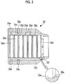
- Fig. 3 is a sectional view showing the housing 33.
- the housing 33 is a cylindrical member, and pedestals 33b including blot holes 33a through which one end portion side of the connection bar 35b is fixed to the housing 33, and heat radiating fins 33c are provided on the outer circumferential surface of the housing 33.
- a plurality of (seven rows in the present embodiment) concave groove portions 33d are provided in an axial direction over the entire circumference on an inner wall surface of the housing 33.
- inclined surfaces 33e are provided by chamfering the corner portions on both end portions in the axial direction.
- stator 32 when the stator 32 described below is inserted and incorporated, since an area between the stator 32 and the inner wall surface of the housing 33 coming into contact with the stator 32 decreases, the stator 32 can be easily inserted into the housing 33 due to reduction of a friction force.
- thermal grease is thinly applied to the inner wall surface of the housing 33, that is, on the entire surface of the inner wall surface of the housing 33 including the concave groove portions 33d.
- the thermal grease contributes to improvement of heat transfer during an operation, and in the step of incorporating the stator 32, also contributes to improved sliding and smooth insertion of the stator 32.
- a reference numeral 33f indicates a grease discharging port through which excess thermal grease is extruded and discharged.
- a metal member is pulled toward a strong permanent magnet of the motor rotor 31, and there is a concern that the metal member may stick and become fixed to the motor rotor 31, or may be damaged. Accordingly, for example, as shown in Fig. 4 , as a tool having a positioning function and a sliding guide function, a guide bar 50 is used. That is, the housing installation step, multiple guide bars 50 are used for positioning and sliding of the housing 33.
- Each of the guide bars 50 is a rod-shaped member which includes a screw portion 51 having the same diameter as that of a hexagon head bolt 36 which fixes the flanged portion 35a to the air guide casing 14, on one end of the guide bar 50, and is used so that the screw portion 51 is screwed into a bolt hole 14a of the air guide casing 14 into which the hexagon head bolt 36 is screwed.
- the guide bar 50 in the state where the guide bar 50 is attached to the air guide casing 14, the guide bar 50 has a sufficient length by which a tip portion of the guide bar 50 opposite to the screw portion 51 is not affected by a magnetic force of the permanent magnet of the motor rotor 31.
- the plurality of guide bars 50 are screwed into the bolt holes 14a so as to be attached.
- the plurality of guide bars 50 are screwed into the bolt holes 14a so as to be attached.
- two guide bars are attached by bolt holes 14a positioned at two locations above and below each other, stable positioning and sliding of the stator support unit HS can be obtained.
- three or more guide bars 50 are used, the positioning and sliding of the state support unit HS can be more stable.
- stator support unit HS is suspended using an eyebolt (not shown) which is provided at an appropriate position, tip portions of the guide bars 50 are inserted into bolt holes 35c of the flanged portion 35a, and the guide bars 50 are positioned. Thereafter, the stator support units HS slides along the guide bars 50 and moves to an installation surface of the air guide casing 14. In this case, even when the stator support unit HS approaches the motor rotor 31 and receives a magnetic force, since the stator support unit HS is held by the guide bars 50, the stator support unit HS cannot be pulled toward the motor rotor 31.
- stator support unit HS which has moved to a predetermined attachment position, hexagon head bolts 36 are sequentially screwed into the bolt holes 35c and 14a into which the guide bars 50 are not screwed, and the stator support unit HS is temporarily fixed. Thereafter, the guide bars 50 are disassembled, the hexagon head bolts 36 are screwed into the bolt holes 35c and 14a, all hexagon head bolts 36 are tightened by a predetermined amount, and fixing with respect to the stator support unit HS is completed. As a result, the stator support unit HS is positioned at the center of the flanged portion 35a and at a position at which the housing 33 coincides with the shaft center of the rotor shaft 15.
- Fig. 5 shows a third step in assembly of the motor, and is a sectional view of a main portion showing a stator installation step of guiding the housing 33 and inserting the stator 32 into the housing 33 so as to be incorporated into the housing 33.
- the third step first, the belt-like member 41 wound around the outer circumference of the protection tube 40 is removed so that the belt-like member 41 does not interfere with the stator.
- the housing 33 is guided so as to be coaxial with the shaft center of the rotor shaft 15, and the stator 32 slides into the housing 33 so as to be incorporated into the housing 33. That is, since an inner diameter of the housing 33 and an outer diameter of the stator 32 are approximately the same as each other, the stator 32 is introduced and inserted into an inner surface of the housing 33 without being positionally deviated in a radial direction. In this case, since thermal grease is applied to the inner surface of the housing 33 and concave groove portions 33d for decreasing a friction force are provided, sliding is improved and smooth insertion can be realized.
- the protection tube 40 is mounted on the motor rotor 31, the inserted stator 32 and the motor rotor 31 do not come into contact with each other. Even when the stator 32 is pulled toward the motor rotor 31, it is possible to protect the motor rotor 31 from impact at the time of contact due to existence of the protection tube 40, and damage of the motor rotor 31 is prevented. In addition, since the stator 32 and the motor rotor 31 are separated from each other due to the plate thickness of the protection tube 40, it can prevent from the motor rotor 31 sticking to the stator 32 by magnet attraction.
- the protection tube 40 may be extracted from the outer circumference of the motor rotor 31 so as to be disassembled.
- a predetermined gap is provided between the outer circumferential surface of the motor rotor 31 and the inner circumferential surface of the stator 32. Accordingly, by setting the thickness of the protection tube 40 so as to be less than the predetermined gap, it is possible to easily extract the stator 32 after the stator 32 is assembled.
- Fig. 6 is a sectional view of a main portion showing a fourth step in assembly of the motor.
- a cap 37 is attached to the tip portion of the housing 33 into which the stator 32 has been inserted, and is fixed by a hexagon socket head bolt 38.
- the stator 32 is held at a predetermined position inside the housing 33, and assembly of the motor 30 is completed.
- for maintenance when a step of disassembling the housing 33 is generated, it is possible to safely and simply disassemble the stator 32 and the motor rotor 31 according to an operation procedure reverse to the assembly procedure.
- Figs. 7 and 8 attachment of the silencer 26 is performed.
- the intermediate piece 27 to which the silencer 26 is attached is attached to the air guide casing 14, and in Fig. 8 , the silencer 26 is attached to the intermediate piece 27.
- accessory wires of the motor 30 side are bundled so as to be inserted into a predetermined wire passage.
- the turbocharger 10 which adopts the motor overhang structure, at the time of the assembly of the motor 30 in which the motor rotor 31 and the stator 32 are sequentially assembled, it is possible to prevent the metal components such as the stator 32 from being pulled toward a permanent magnet, and as a result, an assembly operation of the motor 30 with respect to the rotor shaft 15 can be easily performed.
- the present invention is not limited to the above-described embodiment, and can be appropriately modified within a scope which does not depart from the gist.
Abstract
Description
- The present invention relates to a method of manufacturing a turbocharger and a turbocharger.
- In the related art, a turbocharger which compresses air of an internal combustion engine and feeds air having high density to a combustion chamber is known, and for example, the turbocharger is widely used in a two-stroke low-speed engine such as a marine diesel engine or a diesel engine for generating power. In the turbocharger, a compressor which compresses combustion air and a turbine serving as a drive source of the compressor are coaxially connected to each other, and the compressor and the turbine are accommodated in a casing and are integrally rotated. In addition, the turbocharger turbine is driven by energy held in exhaust gas of an internal combustion engine.
- As the above-described turbocharger, a hybrid turbocharger in which a high-speed motor generator is connected to a rotor shaft is known. Similarly to a general turbocharger, the hybrid turbocharger can supply pressurized combustion air to an internal combustion engine and generate electricity using excess exhaust gas energy to supply power. In addition, when a motor generator of a hybrid turbocharger is installed inside a silencer of a compressor side, in general, the hybrid turbocharger has a size capable of approximately penetrating the silencer.
- In addition, an electric assist turbocharger is known, in which a miniaturized motor is adopted instead of the motor generator of the above-described hybrid turbocharger and the motor is housed in the turbocharger. In the electric assist turbocharger, the miniaturized motor is attached to a shaft extension portion in which a rotor shaft extends in an inlet air passage side. In this case, since a size of the motor is small, it is possible to sufficiently support a weight of the motor rotor by the existing bearings of the turbocharger. Accordingly, in general, a structure in which a dedicated bearing for a motor is not required, that is, a motor overhang structure which does not have a dedicated bearing for a motor is adopted. In the electric assist turbocharger, for example, when a sufficient amount of exhaust gas cannot be obtained during a low load of a main engine, the motor is used to assist turbocharger's compression by consuming electricity to supply enough scavenging pressure to the main engine in place of an auxiliary blower.
- Moreover, PTL 1 below discloses an electric supercharging compressor including rolling bearings which are provided on both sides of an electric motor and support a rotary shaft, and an assembly method thereof.
- [PTL 1]
Japanese Unexamined Patent Application Publication No. 2013-24059 - However, the motor of the above-described electric assist turbocharger adopts the motor overhang structure which does not have a bearing. In the case of the motor overhang structure, since a motor rotor of a miniaturized motor is attached to an extension portion of a rotor shaft, it is not necessary to install a dedicated bearing on the motor rotor, and the motor rotor is supported by bearings (bearing of the rotor shaft) supported by a turbocharger main body.
- In addition, like the above-described hybrid turbocharger or the like, it is possible to use a structure in which a motor has a dedicated bearing. However, in this structure, a structure which allows lubricating oil to circulate through a bearing portion is required, and it is necessary to newly install a lubricating oil pipe and a compression air pipe for oil distribution. In addition, since each of the turbocharger and the motor has a bearing, a diaphragm coupling is required in order to absorb axial displacement and radial misalignment between the turbocharger and the motor, a cost increases, and it is difficult to perform retrofitting.
- Accordingly, when the motor is assembled to the electric assist turbocharger, since a bearing is not provided on the motor, a stator and a motor rotor cannot be assembled to a motor as a single unit, and it is not possible to attach a unified motor structure as it is. Thus it is not possible to install a bearing-less motor as a unified unit unlike a motor having bearings installed as a unified unit with a coupling.
- As a result, it is necessary to sequentially assemble a motor rotor and a stator of a motor, and during assembly of a turbocharger, if other metal members approach a motor rotor having a strong permanent magnet at a predetermined assembly position, there is a problem that the metal members may stick on the motor rotor by a magnetic force, and the metal members become fixed to the motor rotor or the motor rotor may be damaged.
- From the above-described circumstance, in a turbocharger such as the electric assist turbocharger in which the motor overhang structure is adopted, it is desirable to provide measures (manufacturing method) for solving problems generated when the motor rotor and the stator are sequentially assembled and for easily performing an assembly operation.
- The present invention is made to solve the above-described problems, and an object thereof is to provide a method of manufacturing a turbocharger capable of easily performing an operation of sequentially assembling a motor rotor and a stator in a turbocharger in which a motor overhang structure is adopted, and a turbocharger which is assembled according to the method of manufacturing.
- The present invention adopts the following means in order to solve the above-described problems.
- According to a first aspect of the present invention, there is provided a method of manufacturing a turbocharger in which a motor is attached to an end portion of a rotor shaft connected to a compressor portion, the motor including a cylindrical housing, a stator accommodated inside the housing, and a motor rotor which is connected to an end portion of the rotor shaft and includes a permanent magnet rotating inside the stator, the method including: a rotor installation step of connecting and attaching the motor rotor to the rotor shaft; a housing installation step of coaxially fixing and supporting the housing to the rotor shaft; and a stator installation step of guiding the housing, and inserting the stator into the housing such that the stator does not directly come into contact with the motor rotor to incorporate the stator into the housing.
- In the method of manufacturing a turbocharger according to the first aspect, since the rotor installation step of connecting and attaching the motor rotor to the rotor shaft, the housing installation step of coaxially fixing and supporting the housing to the rotor shaft, and the stator installation step of guiding the housing, and inserting the stator into the housing such that the stator does not directly come into contact with the motor rotor to incorporate the stator into the housing are provided, when the stator is inserted into the housing, the stator having approximately the same diameter as the cylindrical housing is inserted into the housing along an inner wall surface of the cylindrical housing. Accordingly, it is possible to prevent the stator from being pulled toward the permanent magnet of the motor rotor, coming into contact with the permanent magnet, and becoming fixed to the permanent magnet.
- In the first aspect, preferably, in the rotor installation step, a protection tube is provided on the motor rotor. Accordingly, in the housing installation step or the stator installation step, it is possible to prevent the housing, the stator, or the like from coming into contact with the motor rotor. In addition, preferably, the protection tube is formed of a material such as nylon which has a sliding property and does not have magnetism.
- In the first aspect, preferably, a step of providing a concave groove portion on an inner circumferential surface of the housing is provided. Accordingly, a contact area between the inserted stator and the inner circumferential surface of the housing is decreased, and it is possible to reduce a generated friction force.
- In this case, preferably, a step of chamfering corner portions of both end portions in an axial direction of the concave groove portion is provided. Accordingly, it is possible to smoothly insert the stator.
- In the first aspect, preferably, a step of applying thermal grease for improving a heat transfer property to an inner wall surface of the housing is provided. Accordingly, heat transfer during an operation increases, and insertion of the stator becomes smoother.
- In this case, preferably, grease discharging ports which extrude excess thermal grease are provided in the housing.
- In the first aspect, preferably, in the housing installation step, multiple guide bars are used to position and slide the housing. By using the guide bars, it is possible to prevent a metal member such as a housing from being pulled toward a strong permanent magnet of the motor rotor, being fixed to the permanent magnet, and being damaged.
- According to a second aspect of the present invention, there is provided a turbocharger including a motor which is attached according to the above-described method of manufacturing a turbocharger.
- According to the turbocharger of the second aspect, since the motor attached according to the above-described method of manufacturing a turbocharger is provided, it is possible to easily manufacture the turbocharger without a metal member being pulled toward the motor rotor having a strong permanent magnet due to a magnetic force of the motor rotor.
- According to the above-described aspects, in a turbocharger which adopts a motor overhang structure, since it is possible to prevent a metal component such as a stator from being pulled toward a strong permanent magnet, being fixed to the permanent magnet, and being damaged when a motor rotor and a stator are sequentially assembled to manufacture a motor, an easy assembly operation of a motor becomes possible. In the motor which adopts the motor overhang structure, since a bearing, which requires lubrication such as circulation of lubricating oil, is not needed, it is possible to easily perform retrofitting to the existing turbocharger and effectively reduce a cost.
-
-
Fig. 1 is a sectional view of a main portion in the vicinity of a motor showing a first step in assembly of the motor in an embodiment of a method of manufacturing a turbocharger and a turbocharger of the present invention. -
Fig. 2 is a view showing a second step in assembly of the motor, (a) is a side view of a main portion of a silencer for the turbocharger when viewed from an attachment direction of the silencer (left-side view ofFig. 2(b) ), and (b) is a sectional view of a main portion in the vicinity of the motor. -
Fig. 3 is a vertical sectional view showing an example of a housing structure of the motor. -
Fig. 4 is a sectional view of a main portion showing a method of attaching a stator support unit using a guide bar. -
Fig. 5 is a sectional view of a main portion in the vicinity of the motor showing a third step in assembly of the motor. -
Fig. 6 is a sectional view of a main portion in the vicinity of the motor showing a fourth step in assembly of the motor. -
Fig. 7 is a sectional view of a main portion in the vicinity of the motor showing a state where an intermediate piece of the silencer for the turbocharger is attached after assembly of the motor is completed. -
Fig. 8 is a sectional view of a main portion in the vicinity of the motor showing a state where the silencer for the turbocharger is attached to the intermediate piece ofFig. 7 . -
Fig. 9 is a vertical sectional view showing a schematic configuration example of the turbocharger according to the present invention. -
Fig. 10 is an enlarged view in the vicinity of the motor of the turbocharger shown inFig. 9 . - Hereinafter, embodiments with respect to a method of manufacturing a turbocharger and a turbocharger according to the present invention will be described with reference to the drawings.
-
Fig. 9 is a vertical sectional view showing a schematic configuration example of an electric assist turbocharger as an example of the turbocharger according to the present invention. For example, an electric assist turbocharger (hereinafter, referred to as a "turbocharger") 10 shown inFig. 9 is provided in a marine diesel engine (not shown) (for example, a low-speed two cycle diesel engine), and is a device which supplies compressed air to an air supply manifold (not shown) which communicates with an inner portion of a cylinder liner (not shown) configuring a marine diesel engine. - As shown in
Fig. 9 , theturbocharger 10 of the present embodiment is configured by integrally connecting a gas inlet casing 11, agas outlet casing 12, a bearingpedestal 13, and an air guide casing 14 of a compressor side by bolts (not shown). Arotor shaft 15 is rotatably supported by a thrust bearing 16 andjournal bearings 17 and 18 which are provided inside the bearingpedestal 13, and includes aturbine 19 configuring a turbine portion on one end portion and a compressor impeller (impeller) 20 configuring a compressor portion on the other end. - The
turbine 19 includesmultiple blades 19a on an outer circumferential portion of the turbine. Theblades 19a are disposed between an exhaust gas introduction passage 22 which is provided in the gas inlet casing 11, and a exhaust gas discharge passage 23 which is provided in thegas outlet casing 12. - Meanwhile, the
compressor impeller 20 includesmultiple blades 20a on an outer circumferential portion of the compressor impeller. Theblades 20a are disposed on a downstream side of an inlet air passage (intake channel) 24 provided in theair guide casing 14. Theinlet air passage 24 is connected to ascroll chamber 25 via acompressor impeller 20, and thescroll chamber 25 is connected to a combustion chamber of an engine via an inlet air passage (not shown). - In addition, the above-described
turbocharger 10 includes asilencer 26 on the upstream side of theinlet air passage 24. Thesilencer 26 is installed in upstream of theinlet air passage 24, that is, air passes through thesilencer 26 before theinlet air passage 24 and air compression. It works as a filter by straightening the passing air and a noise absorber. Thesilencer 26 is supported by theair guide casing 14 via anintermediate piece 27. - Moreover, the
turbocharger 10 of the present embodiment includes amotor 30 which is connected to therotor shaft 15. In themotor 30, a power generation function of a motor generator which is used in a hybrid turbocharger is omitted, and only an electric motoring function is performed. Accordingly, themotor 30 is miniaturized. Therefore, themotor 30 has a structure in which therotor shaft 15 extends to theinlet air passage 24 side so as to attach the motor, that is, has a motor overhang structure in which themotor 30 does not have a dedicated bearing. Accordingly, themotor 30 and themotor rotor 31 described below of themotor 30 are supported by the thrust bearing 16 and thejournal bearings 17 and 18 which support therotor shaft 15. -
Fig. 10 is an enlarged view in the vicinity of the above-describedmotor 30. - The
motor 30 has themotor rotor 31, astator 32, and ahousing 33 as main components. Among these, themotor rotor 31 is a columnar member which includes a permanent magnet on the outer circumferential surface, and one end portion of the motor rotor is connected to an end portion of therotor shaft 15 by a flange connection. In the flange connection, aflange 31a provided on an end portion of therotor shaft 15 which is positioned on theinlet air passage 24 side, and aflange 15a provided an end portion of themotor rotor 31 which is positioned on thecompressor impeller 20 side are joined to each other, and theflanges 31a and theflange 15a are connected to each other using a plurality of bolts and nuts 34. - The
stator 32 is installed so as to be accommodated in thecylindrical housing 33. As shown inFig. 9 , thehousing 33 is supported by theair guide casing 14 via asupport member 35. In addition, thesupport member 35 and theair guide casing 14 are connected to each other by ahexagon head bolt 36, and thesupport member 35 and thehousing 33 are connected to each other by ahexagon head bolt 36. - The
motor rotor 31 passing an axial center portion of thestator 32 is disposed in a hollow portion of thestator 32 in a state where themotor rotor 31 does not come into contact with thestator 32. - In addition, a
cap 37 is attached so as to be fixed to an end portion of thehousing 33, which is positioned on theinlet air passage 24 side, by a hexagonsocket head bolt 38. Thecap 37 is positioned further toward thecompressor impeller 20 side than thesilencer 26. That is, the size of themotor 30 is reduced until a shaft extension portion of therotor shaft 15 does not reach thesilencer 26. - Hereinafter, a manufacturing procedure (manufacturing method) of assembling the
motor 30 to theturbocharger 10 having the above-described configuration will be described with reference toFigs. 1 to 8 . -
Fig. 1 shows a first step in assembly of the motor, and is a sectional view of a main portion showing a rotor installation step of connecting and attaching themotor rotor 31 to therotor shaft 15. In the first step, after assembly of thecompressor impeller 20 is completed, an operation of connecting amotor rotor 31 to an end portion of therotor shaft 15 using a flange connection and mounting aprotection tube 40 on an outer circumferential side of themotor rotor 31 is performed. In addition, when the first step starts, in order to secure workability when themotor rotor 31 is connected to the end portion of therotor shaft 15 using a flange connection, the connection may be performed in a state where theair guide casing 14 is not attached. - In the flange connection between the
rotor shaft 15 and themotor rotor 31, after theflanges rotor shaft 15 and themotor rotor 31 are connected to each other using the plurality of bolts and nuts 34. - In this way, after the
motor rotor 31 is connected to therotor shaft 15, in order to easily perform an operation of the subsequent step, theprotection tube 40 is mounted on therotor motor 31. Preferably, theprotection tube 40 is made from a material which has a sliding property and does not have magnetism, and a plastic-based material such as nylon or polyethylene may be used for theprotection tube 40. As an example of a suitable material, for example, nylon (polyamide resin) equivalent to MC901 (Product Name) can be used. Moreover, theprotection tube 40 has a length by which themotor rotor 31 is completely accommodated and in which theprotection tube 40 protrudes in a direction of thesilencer 26 from an end of thesilencer 26 side of thehousing 33 assembled at a predetermined position in a second step described below. - In addition, preferably, in order to protect the motor rotor when a tool or a bolt is attracted to a magnet portion of the motor rotor and comes into contact with the magnet portion during an operation, for example, a belt-
like member 41 such as nylon is wound outside theprotection tube 40. In addition, after themotor rotor 31 is connected to therotor shaft 15, theguide casing 41 may be fixed at a predetermined position. -
Fig. 2 is a view showing the second step in assembly of the motor and a housing installation step in which thehousing 33 is supported so as to be coaxially fixed to therotor shaft 15,Fig. 2(a) is a side view of a main portion when viewed from an attachment direction of the silencer 26 (left-side view ofFig. 2(b)), and Fig. 2(b) is a sectional view of a main portion in the vicinity of the motor. The second step is a step before thestator 32 is assembled, and a stator support unit HS which is integrated by connecting thehousing 33 and thesupport member 35 to each other is attached at a predetermined position on theair guide casing 14 so as to be coaxial with the shaft center of therotor shaft 15. - The
support member 35 is configured to include a ring-shapedflanged portion 35a and a plurality of (four in the present embodiment) connection bars 35b. Theflanged portion 35a is fixed to theair guide casing 14 by ahexagon head bolt 36, and in theflanged portion 35a, a plurality of (six in the present embodiment)bolt holes 35c are provided at an equal pitch in a circumferential direction of theflanged portion 35a. - Each of the connection bars 35b is a member which connects the
flanged portion 35a and the outer circumferential portion of thehousing 33, and has a function which holds thehousing 33 at an axial center position of theflanged portion 35a. -
Fig. 3 is a sectional view showing thehousing 33. Thehousing 33 is a cylindrical member, and pedestals 33b includingblot holes 33a through which one end portion side of theconnection bar 35b is fixed to thehousing 33, andheat radiating fins 33c are provided on the outer circumferential surface of thehousing 33. - Meanwhile, a plurality of (seven rows in the present embodiment)
concave groove portions 33d are provided in an axial direction over the entire circumference on an inner wall surface of thehousing 33. In addition, in each of theconcave groove portions 33d, in order to prevent thestator 32 from colliding with a corner portion of theconcave groove portions 33d when thestator 32 is incorporated,inclined surfaces 33e are provided by chamfering the corner portions on both end portions in the axial direction. - By providing the above-described
concave groove portions 33d, when thestator 32 described below is inserted and incorporated, since an area between thestator 32 and the inner wall surface of thehousing 33 coming into contact with thestator 32 decreases, thestator 32 can be easily inserted into thehousing 33 due to reduction of a friction force. - In addition, in the second step in assembly of the motor, thermal grease is thinly applied to the inner wall surface of the
housing 33, that is, on the entire surface of the inner wall surface of thehousing 33 including theconcave groove portions 33d. The thermal grease contributes to improvement of heat transfer during an operation, and in the step of incorporating thestator 32, also contributes to improved sliding and smooth insertion of thestator 32. Moreover, areference numeral 33f indicates a grease discharging port through which excess thermal grease is extruded and discharged. - When the stator support unit HS configured as above is attached to the
air guide casing 14, a metal member is pulled toward a strong permanent magnet of themotor rotor 31, and there is a concern that the metal member may stick and become fixed to themotor rotor 31, or may be damaged. Accordingly, for example, as shown inFig. 4 , as a tool having a positioning function and a sliding guide function, aguide bar 50 is used. That is, the housing installation step, multiple guide bars 50 are used for positioning and sliding of thehousing 33. - Each of the guide bars 50 is a rod-shaped member which includes a
screw portion 51 having the same diameter as that of ahexagon head bolt 36 which fixes theflanged portion 35a to theair guide casing 14, on one end of theguide bar 50, and is used so that thescrew portion 51 is screwed into abolt hole 14a of theair guide casing 14 into which thehexagon head bolt 36 is screwed. In addition, in the state where theguide bar 50 is attached to theair guide casing 14, theguide bar 50 has a sufficient length by which a tip portion of theguide bar 50 opposite to thescrew portion 51 is not affected by a magnetic force of the permanent magnet of themotor rotor 31. - In assembly of the stator support unit HS using the
guide bar 50, as an initial preparation step, the plurality of guide bars 50 are screwed into thebolt holes 14a so as to be attached. In this case, if two guide bars are attached bybolt holes 14a positioned at two locations above and below each other, stable positioning and sliding of the stator support unit HS can be obtained. However, if three or more guide bars 50 are used, the positioning and sliding of the state support unit HS can be more stable. - After installation of the guide bars 50 are completed, the stator support unit HS is suspended using an eyebolt (not shown) which is provided at an appropriate position, tip portions of the guide bars 50 are inserted into
bolt holes 35c of theflanged portion 35a, and the guide bars 50 are positioned. Thereafter, the stator support units HS slides along the guide bars 50 and moves to an installation surface of theair guide casing 14. In this case, even when the stator support unit HS approaches themotor rotor 31 and receives a magnetic force, since the stator support unit HS is held by the guide bars 50, the stator support unit HS cannot be pulled toward themotor rotor 31. - In this way, in the stator support unit HS which has moved to a predetermined attachment position,
hexagon head bolts 36 are sequentially screwed into the bolt holes 35c and 14a into which the guide bars 50 are not screwed, and the stator support unit HS is temporarily fixed. Thereafter, the guide bars 50 are disassembled, thehexagon head bolts 36 are screwed into the bolt holes 35c and 14a, allhexagon head bolts 36 are tightened by a predetermined amount, and fixing with respect to the stator support unit HS is completed. As a result, the stator support unit HS is positioned at the center of theflanged portion 35a and at a position at which thehousing 33 coincides with the shaft center of therotor shaft 15. -
Fig. 5 shows a third step in assembly of the motor, and is a sectional view of a main portion showing a stator installation step of guiding thehousing 33 and inserting thestator 32 into thehousing 33 so as to be incorporated into thehousing 33. In the third step, first, the belt-like member 41 wound around the outer circumference of theprotection tube 40 is removed so that the belt-like member 41 does not interfere with the stator. - Thereafter, the
housing 33 is guided so as to be coaxial with the shaft center of therotor shaft 15, and thestator 32 slides into thehousing 33 so as to be incorporated into thehousing 33. That is, since an inner diameter of thehousing 33 and an outer diameter of thestator 32 are approximately the same as each other, thestator 32 is introduced and inserted into an inner surface of thehousing 33 without being positionally deviated in a radial direction. In this case, since thermal grease is applied to the inner surface of thehousing 33 andconcave groove portions 33d for decreasing a friction force are provided, sliding is improved and smooth insertion can be realized. - In addition, since the
protection tube 40 is mounted on themotor rotor 31, the insertedstator 32 and themotor rotor 31 do not come into contact with each other. Even when thestator 32 is pulled toward themotor rotor 31, it is possible to protect themotor rotor 31 from impact at the time of contact due to existence of theprotection tube 40, and damage of themotor rotor 31 is prevented. In addition, since thestator 32 and themotor rotor 31 are separated from each other due to the plate thickness of theprotection tube 40, it can prevent from themotor rotor 31 sticking to thestator 32 by magnet attraction. - In this way, after the
stator 32 is incorporated into thehousing 33 at a predetermined position inside thehousing 33, theprotection tube 40 may be extracted from the outer circumference of themotor rotor 31 so as to be disassembled. In addition, in themotor 30, a predetermined gap is provided between the outer circumferential surface of themotor rotor 31 and the inner circumferential surface of thestator 32. Accordingly, by setting the thickness of theprotection tube 40 so as to be less than the predetermined gap, it is possible to easily extract thestator 32 after thestator 32 is assembled. -
Fig. 6 is a sectional view of a main portion showing a fourth step in assembly of the motor. In the fourth step, acap 37 is attached to the tip portion of thehousing 33 into which thestator 32 has been inserted, and is fixed by a hexagonsocket head bolt 38. As a result, thestator 32 is held at a predetermined position inside thehousing 33, and assembly of themotor 30 is completed. In addition, for maintenance, when a step of disassembling thehousing 33 is generated, it is possible to safely and simply disassemble thestator 32 and themotor rotor 31 according to an operation procedure reverse to the assembly procedure. - Thereafter, as shown in
Figs. 7 and8 , attachment of thesilencer 26 is performed. InFig. 7 , theintermediate piece 27 to which thesilencer 26 is attached is attached to theair guide casing 14, and inFig. 8 , thesilencer 26 is attached to theintermediate piece 27. In addition, before thesilencer 26 is attached to theintermediate piece 27, accessory wires of themotor 30 side are bundled so as to be inserted into a predetermined wire passage. - According to the above-described embodiment, in the
turbocharger 10 which adopts the motor overhang structure, at the time of the assembly of themotor 30 in which themotor rotor 31 and thestator 32 are sequentially assembled, it is possible to prevent the metal components such as thestator 32 from being pulled toward a permanent magnet, and as a result, an assembly operation of themotor 30 with respect to therotor shaft 15 can be easily performed. - In addition, in the
motor 30 of theturbocharger 10 which adopts the motor overhang structure, a bearing which requires lubrication performed by lubricating oil is not needed. Accordingly, since lubricating oil is not required, it is possible to easily perform retrofitting to the existing turbocharger and easily reduce a cost. - Moreover, the present invention is not limited to the above-described embodiment, and can be appropriately modified within a scope which does not depart from the gist.
-
- 10:
- electric assist turbocharger (turbocharger)
- 11:
- gas inlet casing
- 12:
- gas outlet casing
- 13:
- bearing pedestal
- 14:
- air guide casing
- 15:
- rotor shaft
- 19:
- turbine
- 20:
- compressor impeller
- 22:
- exhaust gas introduction passage
- 23:
- exhaust gas discharge passage
- 24:
- inlet air passage
- 25:
- scroll chamber
- 26:
- silencer
- 30:
- motor
- 31:
- motor rotor
- 32:
- stator
- 33:
- housing
- 35:
- support member
- 36:
- hexagon head bolt
- 37:
- gap
- 40:
- protection tube
- 41:
- belt-like member
- 50:
- guide bar
- HS:
- stator support unit
Claims (8)
- A method of manufacturing a turbocharger in which a motor is attached to an end portion of a rotor shaft connected to a compressor portion, the motor including a cylindrical housing, a stator accommodated inside the housing, and a motor rotor which is connected to an end portion of the rotor shaft and includes permanent magnets rotating inside the stator, the method comprising:a rotor installation step of connecting and attaching the motor rotor to the rotor shaft;a housing installation step of coaxially fixing and supporting the housing to the rotor shaft; anda stator installation step of guiding the housing, and inserting the stator into the housing such that the stator does not directly come into contact with the motor rotor to incorporate the stator into the housing.
- The method of manufacturing a turbocharger according to claim 1,
wherein in the rotor installation step, a protection tube is provided on the motor rotor. - The method of manufacturing a turbocharger according to claim 1 or 2, further comprising;
a step of forming a concave groove portion on an inner circumferential surface of the housing. - The method of manufacturing a turbocharger according to claim 3, further comprising;
a step of chamfering corner portions of both end portions in an axial direction of the concave groove portion. - The method of manufacturing a turbocharger according to any one of claims 1 to 4, further comprising;
a step of applying thermal grease to an inner wall surface of the housing. - The method of manufacturing a turbocharger according to claim 5,
wherein a grease discharging port which extrudes excess thermal grease is provided in the housing. - The method of manufacturing a turbocharger according to any one of claims 1 to 6,
wherein in the housing installation step, a guide bar is used to position and slide the housing. - A turbocharger including a motor which is attached by the method of manufacturing a turbocharger according to any one of claims 1 to 7.
Applications Claiming Priority (2)
| Application Number | Priority Date | Filing Date | Title |
|---|---|---|---|
| JP2014042073A JP5894203B2 (en) | 2014-03-04 | 2014-03-04 | Supercharger manufacturing method |
| PCT/JP2015/054930 WO2015133303A1 (en) | 2014-03-04 | 2015-02-23 | Supercharger manufacturing method and supercharger |
Publications (2)
| Publication Number | Publication Date |
|---|---|
| EP2977588A1 true EP2977588A1 (en) | 2016-01-27 |
| EP2977588A4 EP2977588A4 (en) | 2016-07-20 |
Family
ID=54055113
Family Applications (1)
| Application Number | Title | Priority Date | Filing Date |
|---|---|---|---|
| EP15759319.5A Withdrawn EP2977588A4 (en) | 2014-03-04 | 2015-02-23 | Supercharger manufacturing method and supercharger |
Country Status (6)
| Country | Link |
|---|---|
| US (1) | US10180143B2 (en) |
| EP (1) | EP2977588A4 (en) |
| JP (1) | JP5894203B2 (en) |
| KR (1) | KR101644287B1 (en) |
| CN (1) | CN105074160B (en) |
| WO (1) | WO2015133303A1 (en) |
Cited By (2)
| Publication number | Priority date | Publication date | Assignee | Title |
|---|---|---|---|---|
| FR3055754A1 (en) * | 2016-09-02 | 2018-03-09 | Danfoss Silicon Power Gmbh | ROTOR FOR A HIGH SPEED ELECTRIC MOTOR |
| EP3626940A1 (en) * | 2018-09-20 | 2020-03-25 | Robert Bosch GmbH | Electric drive machine for a compressor and/or a turbine, turbocharger and/or turbine |
Families Citing this family (11)
| Publication number | Priority date | Publication date | Assignee | Title |
|---|---|---|---|---|
| JP5894203B2 (en) | 2014-03-04 | 2016-03-23 | 三菱重工業株式会社 | Supercharger manufacturing method |
| DE102016100819A1 (en) * | 2015-02-20 | 2016-08-25 | Abb Turbo Systems Ag | coupling device |
| JP6589217B2 (en) * | 2015-04-17 | 2019-10-16 | 三菱重工コンプレッサ株式会社 | Rotating machine, method of manufacturing rotating machine |
| JP6563321B2 (en) * | 2015-12-03 | 2019-08-21 | 三菱重工業株式会社 | Electric motor support mechanism, compressor, and supercharger |
| US10077785B2 (en) * | 2016-04-21 | 2018-09-18 | Mitsubishi Heavy Industries, Ltd. | Impeller assembly, turbocharger, and method of assembling impeller assembly |
| DE202016102995U1 (en) * | 2016-06-06 | 2017-09-07 | Max Baermann Gmbh | Magnetic rotating member |
| DE102016221639B4 (en) * | 2016-11-04 | 2021-11-25 | Ford Global Technologies, Llc | Supercharged internal combustion engine with a cooled compressor |
| CN106451946B (en) * | 2016-12-22 | 2023-05-02 | 珠海精实测控技术股份有限公司 | Rotor assembly all-in-one |
| US10704556B2 (en) | 2017-08-30 | 2020-07-07 | Mitsubishi Heavy Industries, Ltd. | Motor, turbocharger and assembly method turbocharger |
| FR3092448B1 (en) * | 2019-02-04 | 2021-01-15 | Ifp Energies Now | Device for compressing a fluid driven by an electric machine with a rotor equipped with a solid cylindrical magnet |
| JP2021013223A (en) * | 2019-07-04 | 2021-02-04 | 本田技研工業株式会社 | Rotary electric machine assembly device and rotary electric machine assembly method |
Family Cites Families (35)
| Publication number | Priority date | Publication date | Assignee | Title |
|---|---|---|---|---|
| CA701612A (en) * | 1958-11-04 | 1965-01-12 | W. Wightman Lawrance | Dynamoelectric machines and methods of manufacture for same |
| US3268986A (en) * | 1963-05-07 | 1966-08-30 | Gen Electric | Method of manufacturing dynamo-electric machines |
| GB1192792A (en) * | 1967-05-18 | 1970-05-20 | Ranco Motors Ltd | A method of Electric Motor Assembly |
| US5767596A (en) * | 1996-10-03 | 1998-06-16 | General Electric Company | Dynamoelectric machine and processes for making the same |
| US6321439B1 (en) * | 1997-01-21 | 2001-11-27 | Siemens Westinghouse Power Corporation | Method for assembly of a stator in the field |
| US6305169B1 (en) * | 1999-02-22 | 2001-10-23 | Ralph P. Mallof | Motor assisted turbocharger |
| GB2354553B (en) * | 1999-09-23 | 2004-02-04 | Turbo Genset Company Ltd The | Electric turbocharging system |
| US6739845B2 (en) * | 2002-05-30 | 2004-05-25 | William E. Woollenweber | Compact turbocharger |
| US7025579B2 (en) * | 2001-10-16 | 2006-04-11 | Innovative Turbo Systems Corporation | Bearing system for high-speed rotating machinery |
| JP2004023901A (en) | 2002-06-17 | 2004-01-22 | Minebea Co Ltd | Rotor of motor and manufacturing method therefor |
| JP4426259B2 (en) * | 2003-11-19 | 2010-03-03 | 株式会社日立製作所 | Gas turbine equipment and gas turbine power generation equipment |
| US7353586B2 (en) * | 2004-04-26 | 2008-04-08 | Siemens Power Generation, Inc. | Method of horizontally stacking a stator core within a stator frame |
| US7653986B2 (en) * | 2004-04-26 | 2010-02-02 | Siemens Energy, Inc. | Horizontal assembly of stator core using keybar extensions |
| DE102004029828A1 (en) | 2004-06-19 | 2006-01-19 | Daimlerchrysler Ag | Exhaust gas turbocharger for an internal combustion engine and method for operating an Agbasturbolader |
| JP4591828B2 (en) * | 2005-08-22 | 2010-12-01 | 株式会社Ihi | Supercharger with electric motor |
| JP4247217B2 (en) * | 2005-08-25 | 2009-04-02 | 三菱重工業株式会社 | Exhaust turbine turbocharger |
| CN101573516B (en) * | 2007-02-09 | 2011-06-15 | 三菱重工业株式会社 | Exhaust gas turbocharger |
| JP4648347B2 (en) * | 2007-02-23 | 2011-03-09 | 三菱重工業株式会社 | Hybrid exhaust turbine turbocharger |
| JP4898491B2 (en) * | 2007-02-23 | 2012-03-14 | 三菱重工業株式会社 | Power turbine test equipment |
| DE102007062540A1 (en) * | 2007-12-20 | 2009-06-25 | Sycotec Gmbh & Co. Kg | Electric motor or generator |
| FI122036B (en) * | 2008-01-10 | 2011-07-29 | Waertsilae Finland Oy | Piston engine turbocharger arrangement |
| FI121800B (en) * | 2008-01-10 | 2011-04-15 | Waertsilae Finland Oy | Piston engine supercharging |
| US7699097B2 (en) | 2008-06-11 | 2010-04-20 | Digitek Technology Co., Ltd. | Mover stabilizing and stator cooling arrangement of a 3-phase linear motor of a submersible oil pump |
| US20110025144A1 (en) * | 2009-07-28 | 2011-02-03 | Caterpillar, Inc. | Cooling housing for a switched reluctance electric device |
| EP2385614B1 (en) | 2010-05-06 | 2013-03-27 | The Switch Drive Systems Oy | An electrical machine and a method for assembling it |
| JP5529714B2 (en) * | 2010-11-12 | 2014-06-25 | 三菱重工業株式会社 | Electric supercharger rotating shaft support structure |
| JP2012177330A (en) * | 2011-02-25 | 2012-09-13 | Mitsubishi Heavy Ind Ltd | Hybrid supercharger |
| JP2012197684A (en) * | 2011-03-18 | 2012-10-18 | Mitsubishi Heavy Ind Ltd | Single-shaft two-stage supercharger |
| JP2012229676A (en) * | 2011-04-27 | 2012-11-22 | Ihi Corp | Attachment structure of heat shield plate and supercharger |
| JP5535992B2 (en) * | 2011-07-15 | 2014-07-02 | 三菱重工業株式会社 | Electric supercharged compressor, its assembly method and internal combustion engine |
| GB2497113B (en) | 2011-12-01 | 2017-03-01 | Cummins Ltd | Turbocharger arrangement including a generator |
| TWI472129B (en) * | 2012-11-21 | 2015-02-01 | Ind Tech Res Inst | Stator structure |
| US20140190001A1 (en) * | 2013-01-04 | 2014-07-10 | Michael P. Jaszcar | Rail system for installing a stator core in a frame |
| JP5863720B2 (en) | 2013-07-10 | 2016-02-17 | 三菱重工業株式会社 | Silencer for turbocharger |
| JP5894203B2 (en) | 2014-03-04 | 2016-03-23 | 三菱重工業株式会社 | Supercharger manufacturing method |
-
2014
- 2014-03-04 JP JP2014042073A patent/JP5894203B2/en active Active
-
2015
- 2015-02-23 US US14/787,658 patent/US10180143B2/en active Active
- 2015-02-23 CN CN201580000467.9A patent/CN105074160B/en active Active
- 2015-02-23 EP EP15759319.5A patent/EP2977588A4/en not_active Withdrawn
- 2015-02-23 KR KR1020157026692A patent/KR101644287B1/en active IP Right Grant
- 2015-02-23 WO PCT/JP2015/054930 patent/WO2015133303A1/en active Application Filing
Cited By (2)
| Publication number | Priority date | Publication date | Assignee | Title |
|---|---|---|---|---|
| FR3055754A1 (en) * | 2016-09-02 | 2018-03-09 | Danfoss Silicon Power Gmbh | ROTOR FOR A HIGH SPEED ELECTRIC MOTOR |
| EP3626940A1 (en) * | 2018-09-20 | 2020-03-25 | Robert Bosch GmbH | Electric drive machine for a compressor and/or a turbine, turbocharger and/or turbine |
Also Published As
| Publication number | Publication date |
|---|---|
| CN105074160B (en) | 2016-12-21 |
| EP2977588A4 (en) | 2016-07-20 |
| KR20150119465A (en) | 2015-10-23 |
| CN105074160A (en) | 2015-11-18 |
| JP2015169073A (en) | 2015-09-28 |
| JP5894203B2 (en) | 2016-03-23 |
| US10180143B2 (en) | 2019-01-15 |
| KR101644287B1 (en) | 2016-07-29 |
| US20160369817A1 (en) | 2016-12-22 |
| WO2015133303A1 (en) | 2015-09-11 |
Similar Documents
| Publication | Publication Date | Title |
|---|---|---|
| US10180143B2 (en) | Method of manufacturing turbocharger and turbocharger | |
| US11396889B2 (en) | Supercharger and motor cooling method | |
| US8174141B2 (en) | Turbo generator | |
| EP2247838B1 (en) | Supercharger arrangement for a piston engine | |
| US9284918B2 (en) | Hybrid exhaust gas turbocharger | |
| EP2229515B1 (en) | Turbocharger arrangement for a piston engine | |
| ITTO20100498A1 (en) | MOTOR WITH INTERNAL COMBUSTION OVERHEADED | |
| WO2017220324A1 (en) | Electric compressor with compact bearing means | |
| US20150104301A1 (en) | Motor housing for a cabin air compressor | |
| EP3159507B1 (en) | Oil supply conduit through stator lamination stack for electrified turbocharger | |
| JP6682374B2 (en) | Electric supercharged compressor | |
| CN107701298B (en) | Compressor and supercharger | |
| US10704556B2 (en) | Motor, turbocharger and assembly method turbocharger | |
| WO2017183544A1 (en) | Impeller assembly, supercharger, and method for assembling impeller assembly | |
| RU158763U1 (en) | INFLATED COMBUSTION ENGINE | |
| WO2019117045A1 (en) | Supercharger |
Legal Events
| Date | Code | Title | Description |
|---|---|---|---|
| PUAI | Public reference made under article 153(3) epc to a published international application that has entered the european phase |
Free format text: ORIGINAL CODE: 0009012 |
|
| 17P | Request for examination filed |
Effective date: 20151020 |
|
| AK | Designated contracting states |
Kind code of ref document: A1 Designated state(s): AL AT BE BG CH CY CZ DE DK EE ES FI FR GB GR HR HU IE IS IT LI LT LU LV MC MK MT NL NO PL PT RO RS SE SI SK SM TR |
|
| AX | Request for extension of the european patent |
Extension state: BA ME |
|
| A4 | Supplementary search report drawn up and despatched |
Effective date: 20160617 |
|
| RIC1 | Information provided on ipc code assigned before grant |
Ipc: H02K 1/12 20060101ALI20160613BHEP Ipc: F02B 39/10 20060101ALI20160613BHEP Ipc: F04D 25/06 20060101ALI20160613BHEP Ipc: H02K 15/16 20060101ALI20160613BHEP Ipc: H02K 15/03 20060101ALI20160613BHEP Ipc: F04D 29/62 20060101ALI20160613BHEP Ipc: F02B 39/00 20060101ALI20160613BHEP Ipc: F01D 15/10 20060101ALI20160613BHEP Ipc: F04D 25/02 20060101ALI20160613BHEP Ipc: H02K 7/14 20060101ALI20160613BHEP Ipc: H02K 15/14 20060101ALI20160613BHEP Ipc: F02B 37/10 20060101AFI20160613BHEP Ipc: H02K 1/18 20060101ALI20160613BHEP Ipc: H02K 7/18 20060101ALI20160613BHEP Ipc: H02K 1/27 20060101ALI20160613BHEP |
|
| DAX | Request for extension of the european patent (deleted) | ||
| STAA | Information on the status of an ep patent application or granted ep patent |
Free format text: STATUS: THE APPLICATION IS DEEMED TO BE WITHDRAWN |
|
| 18D | Application deemed to be withdrawn |
Effective date: 20170117 |