JP5888602B2 - Auxiliary drive - Google Patents
Auxiliary drive Download PDFInfo
- Publication number
- JP5888602B2 JP5888602B2 JP2012089991A JP2012089991A JP5888602B2 JP 5888602 B2 JP5888602 B2 JP 5888602B2 JP 2012089991 A JP2012089991 A JP 2012089991A JP 2012089991 A JP2012089991 A JP 2012089991A JP 5888602 B2 JP5888602 B2 JP 5888602B2
- Authority
- JP
- Japan
- Prior art keywords
- pulley
- belt
- auxiliary
- crank pulley
- crank
- Prior art date
- Legal status (The legal status is an assumption and is not a legal conclusion. Google has not performed a legal analysis and makes no representation as to the accuracy of the status listed.)
- Active
Links
Images


Description
この発明は、補機の駆動装置に係り、特にクランクプーリの回転によって駆動される補機の駆動装置に関する。 The present invention relates to an accessory drive device, and more particularly, to an accessory drive device driven by rotation of a crank pulley.
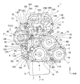
図6、図7において、101は車両に横置きに搭載される内燃機関、102はシリンダブロック、103はシリンダヘッド、104はシリンダヘッドカバー、105はオイルパンである。シリンダブロック102とシリンダヘッド103とは、機関本体106を構成する。
この機関本体106には、右方の端部でカバー(チェーンケース)107が複数のボルトによって所定箇所で締結されている。具体的には、カバー107は、前部で下部位から上方に向かって配置された第1〜第4前側ボルト108A〜108Dにより、また、後部で下部位から上方に向かって配置された第1〜第8後側ボルト109A〜109Hにより、さらに、中央且つ上部で前後方向に並んだ第1〜第3中央側ボルト110A〜110Cにより、機関本体106の右端部に締結されている。このカバー107は、第1〜第4前側ボルト108A〜108D・第1〜第8後側ボルト109A〜109H・第1〜第3中央側ボルト110A〜110Cが貫通する第1〜第4前側ボス部111A〜111D・第1〜第8後側ボス部112A〜112H・第1〜第3中央側ボス部113A〜113Cを、所定箇所で備える。
シリンダブロック102の下部の中央部位には、車両幅方向(左右方向)に指向し、端部114Aがカバー107を貫通して右方で且つ外方に突出するクランク軸114が軸支されている。このクランク軸114の突出した端部114Aには、クランクプーリ115が取り付けられている。クランクプーリ115は、図6、図8に示すように、右方からの側面視で、時計方向の回転方向Rに回転する。
6 and 7,
A cover (chain case) 107 is fastened to the
A
機関本体106には、空調用コンプレッサプーリ116を備えた空調用コンプレッサ117と、ウォータポンププーリ118を備えたウォータポンプ119と、補機プーリ120を備えた補機(オルタネータ)121とが設置される。
空調用コンプレッサプーリ116は、空調用コンプレッサプーリ軸122に支持され、クランクプーリ115と略同じ高さ位置で且つクランクプーリ115よりも車両前方に配置されている。
ウォータポンププーリ118は、ウォータポンププーリ軸123に支持され、クランクプーリ115と空調用コンプレッサプーリ116との間で且つクランクプーリ115及び空調用コンプレッサプーリ116よりも上方に配置されている。
補機プーリ120は、補機プーリ軸124に支持され、クランクプーリ115よりも上方で且つ車両後方に配置されている。
補機121は、下部位が第4後側ボルト109Dによって機関本体106に支持されているとともに、上部位がブラケット125を介して第7〜第8後側ボルト109G〜109Hによって機関本体106に支持されている。
また、機関本体106には、クランクプーリ115と補機プーリ120との間で且つクランクプーリ115の上方で、アイドラプーリ126が配置されている。このアイドラプーリ126は、アイドラプーリ軸127に支持されている。
The
The air-
The
The
The
Further, an
また、機関本体106には、補機121の駆動装置128が設けられる。
この駆動装置128にあっては、クランクプーリ115とアイドラプーリ126と補機プーリ120とウォータポンププーリ118と空調用コンプレッサプーリ116とに、ベルト129が巻き掛けられている。この場合、このベルト129は、クランクプーリ115と補機プーリ120とウォータポンププーリ118と空調用コンプレッサプーリ116とに内側面が接するとともに、アイドラプーリ126には外側面(背面)が接して配置される。
クランクプーリ115からベルト129を介して駆動力が伝達される補機プーリ120は、図6、図8に示すように、ベルト129の走行方向でクランクプーリ115からベルト129が送出される側(後方側)に配置される。
このような各部品の配置構造において、機関本体106には、クランクプーリ115と補機プーリ120との間に配置したアイドラプーリ126によってベルト129の走行ラインをクランクプーリ115と補機プーリ120とに接する接線Tよりも内側に湾曲させてベルト129の走行ラインに内側へ窪む凹部130が形成される。
この場合、図8に示すように、クランクプーリ115に掛かるベルト129の部分で巻上げられた下方からの水が補機121に掛りやすい構造であったり、カバー107のボス部として、特に、図7に示すように、クランクプーリ115の後方に位置する第2後側ボス部112Bが、ベルト129の端面より低い位置(シリンダブロック102側)に存在する構造であった。つまり、第2後側ボス部112Bは、カバー107の凹み面部(シリンダブロック102とのシール面部)107Cに形成され、カバー107の突出面部107Aへ達しない高さで配置されている。
The
In this
As shown in FIGS. 6 and 8, the
In such an arrangement structure of each component, the engine
In this case, as shown in FIG. 8, the structure is such that the water from the lower part wound around the
特許文献1に係る内燃機関の補機駆動ベルト装置は、ベルトの背面(外側面)のアイドラプーリに対する接触開始側とアイドラプーリとで挟まれる空間を覆う遮蔽部材を、アイドラプーリの回転軸に取り付けた構造である。 In an auxiliary machine driving belt device for an internal combustion engine according to Patent Document 1, a shielding member that covers a space sandwiched between an idler pulley on the back surface (outer surface) of the belt and the idler pulley is attached to a rotating shaft of the idler pulley Structure.
ところが、図6、図7に示す内燃機関の補機の配置にあっては、図6、図8に示すように、負荷の大きい補機121周辺へ水が掛りやすく、このため、ベルト滑り・ベルト鳴きが発生しやすくなり、また、補機121の水掛りが激しい場合に、故障の原因となりやすく、さらに、カバー107の各ボス部が機関本体106に固定する以外の効果を持たなく、改善が望まれていた。
However, in the arrangement of the auxiliary machine of the internal combustion engine shown in FIGS. 6 and 7, as shown in FIGS. 6 and 8, water is likely to splash around the
そこで、この発明の目的は、補機プーリへの被水を遮蔽し、ベルト滑り・ベルト鳴きを防止する補機の駆動装置を提供することにある。 SUMMARY OF THE INVENTION Accordingly, an object of the present invention is to provide a drive device for an auxiliary machine that shields water from being applied to the auxiliary machine pulley and prevents belt slippage and squealing.
この発明は、内燃機関の機関本体の端部に複数のボルトによって締結されるカバーを配置し、前記カバーを貫通して外方へ突出するクランク軸の端部にクランクプーリを取り付け、前記クランクプーリからベルトを介して駆動力が伝達される補機プーリを前記ベルトの走行方向で前記クランクプーリから前記ベルトが送出される側に配置し、前記クランクプーリと前記補機プーリとの間に配置したアイドラプーリによって前記ベルトの走行ラインを前記クランクプーリと前記補機プーリとに接する接線よりも内側に湾曲させて前記ベルトの走行ラインに内側へ窪む凹部を形成した補機の駆動装置において、前記カバーは前記ボルトが貫通するボス部を複数箇所で備え、前記複数のボス部のうち少なくとも一つのボス部を前記凹部内に配置するとともに前記凹部内に配置されたボス部を前記クランクプーリの幅方向全幅を覆う高さまで突出する突出ボス部として設定し、前記クランクプーリの前記ベルトが巻き付けられた区間と前記補機プーリの前記ベルトが巻き付けられた区間とに接する接線を第1接線とし、前記クランクプーリの前記ベルトが巻き付けられた区間と前記補機プーリの前記ベルトが巻き付けられていない区間とに接する接線を第2接線とした場合に、前記突出ボス部は、前記第1接線と前記第2接線とに囲まれた領域内に配置され、外周面が前記第1接線又は前記第2接線の少なくとも一方に接して前記領域を前記クランクプーリ側と前記補機プーリ側とに仕切るような直径に設定されたことを特徴とする。 According to the present invention, a cover that is fastened by a plurality of bolts is disposed at an end of an engine body of an internal combustion engine, a crank pulley is attached to an end of a crankshaft that penetrates the cover and protrudes outward, and the crank pulley The auxiliary pulley to which the driving force is transmitted from the belt through the belt is arranged on the side where the belt is sent from the crank pulley in the running direction of the belt, and is arranged between the crank pulley and the auxiliary pulley. In the drive device for an auxiliary machine, in which a running line of the belt is curved inward with respect to a tangent line contacting the crank pulley and the auxiliary machine pulley by an idler pulley, and a recess recessed inward is formed in the running line of the belt . It said cover has a boss portion to which the bolt penetrates at a plurality of locations, placing at least one boss portion of the plurality of boss portions in the recess Both sets a boss portion disposed in the recess as a projecting boss portion projecting to a height to cover the width direction overall width of the crank pulley, the belt of the crank pulley the belt is wound section of the accessory pulley A tangent line that contacts the section around which the belt is wound is a first tangent line, and a tangent line that contacts the section where the belt of the crank pulley is wound and a section where the belt of the auxiliary pulley is not wound is a second tangent line. In this case, the protruding boss portion is disposed in a region surrounded by the first tangent and the second tangent, and an outer peripheral surface is in contact with at least one of the first tangent or the second tangent. The diameter is set so as to partition the crank pulley side and the auxiliary pulley side .
この発明は、補機プーリへの被水を遮蔽し、ベルト滑り・ベルト鳴きを防止することができる。 According to the present invention, it is possible to shield water from being applied to the auxiliary pulley and prevent belt slippage and squealing.
この発明は、補機プーリへの被水を遮蔽し、ベルト滑り・ベルト鳴きを防止する目的を、カバーにはボルトが貫通するボス部を複数箇所備え、ボス部のうち少なくとも一つのボス部を凹部内に配置するとともに、この凹部内に配置されたボス部をクランクプーリの幅方向全幅を覆う高さに突出する突出ボス部として設定して実現するものである。 The present invention provides a cover with a plurality of boss portions through which bolts penetrate, and covers at least one boss portion among the boss portions, for the purpose of shielding water from the auxiliary machine pulley and preventing belt slippage and squealing. In addition to being disposed in the recess, the boss portion disposed in the recess is set as a projecting boss portion projecting at a height that covers the entire width of the crank pulley in the width direction.
図1〜図4は、この発明の実施例を示すものである。
図1〜図3において、1は車両に横置きに搭載される内燃機関、2はシリンダブロック、3はシリンダヘッド、4はシリンダヘッドカバー、5はオイルパンである。シリンダブロック2とシリンダヘッド3とは、機関本体6を構成する。
この機関本体6には、右方の端部でカバー(チェーンケース)7が複数のボルトによって所定箇所で締結されている。具体的には、カバー7は、前部で下部位から上方に向かって配置された第1〜第4前側ボルト8A〜8Dにより、また、後部で下部位から上方に向かって配置された第1〜第8後側ボルト9A〜9Hにより、さらに、中央且つ上部で前後方向に並んだ第1〜第3中央側ボルト10A〜10Cにより、機関本体6の右端部に締結されている。このカバー7は、第1〜第4前側ボルト8A〜8D・第1〜第8後側ボルト9A〜9H・第1〜第3中央側ボルト10A〜10Cが貫通する第1〜第4前側ボス部11A〜11D・第1〜第8後側ボス部12A〜12H・第1〜第3中央側ボス部13A〜13Cを、所定箇所で備える。
シリンダブロック2の下部の中央部位には、車両幅方向(左右方向)に指向し、端部14Aがカバー7を貫通して右方で且つ外方に突出するクランク軸14が軸支されている。このクランク軸14の突出した端部14Aには、クランクプーリ15が取り付けられている。クランクプーリ15は、図1、図4に示すように、右方からの側面視で、時計方向の回転方向Rに回転する。
1 to 4 show an embodiment of the present invention.
1 to 3, reference numeral 1 denotes an internal combustion engine mounted horizontally on a vehicle, 2 a cylinder block, 3 a cylinder head, 4 a cylinder head cover, and 5 an oil pan. The
A cover (chain case) 7 is fastened to the
A
機関本体6には、空調用コンプレッサプーリ16を備えた空調用コンプレッサ17と、ウォータポンププーリ18を備えたウォータポンプ19と、補機プーリ20を備えた補機(オルタネータ)21とが設置される。
空調用コンプレッサプーリ16は、空調用コンプレッサプーリ軸22に支持され、クランクプーリ15と略同じ高さ位置で且つクランクプーリ15よりも車両前方に配置されている。
ウォータポンププーリ18は、ウォータポンププーリ軸23に支持され、クランクプーリ15と空調用コンプレッサプーリ16との間で且つクランクプーリ15及び空調用コンプレッサプーリ16よりも上方に配置されている。
補機プーリ20は、補機プーリ軸24に支持され、クランクプーリ15よりも上方で且つ車両後方に配置されている。
補機21は、下部位が第4後側ボルト9Dによって機関本体6に支持されているとともに、上部位がブラケット25を介して第7〜第8後側ボルト9G〜9Hによって機関本体6に支持されている。
また、機関本体6には、クランクプーリ15と補機プーリ20との間で且つクランクプーリ15の上方で、アイドラプーリ26が配置されている。このアイドラプーリ26は、アイドラプーリ軸27に支持されている。
The
The air-
The
The
The
An
また、機関本体6には、補機21の駆動装置28が設けられる。
この駆動装置28にあっては、クランクプーリ15とアイドラプーリ26と補機プーリ20とウォータポンププーリ18と空調用コンプレッサプーリ16とに、ベルト29が巻き掛けられている。この場合、このベルト29は、クランクプーリ15と補機プーリ20とウォータポンププーリ18と空調用コンプレッサプーリ16とに内側面が接するとともに、アイドラプーリ26には外側面(背面)が接して配置される。
クランクプーリ15からベルト29を介して駆動力が伝達される補機プーリ20は、図1、図4に示すように、ベルト29の走行方向でクランクプーリ15からベルト29が送出される側(後方側)に配置される。
このような各部品の配置構造において、図4に示すように、機関本体6には、右端部で、クランクプーリ15と補機プーリ20との間に配置したアイドラプーリ26によってベルト29の走行ラインをクランクプーリ15と補機プーリ20とに接する接線Tよりも内側に湾曲させてベルト29の走行ラインに内側へ窪む凹部30が形成される。
The
In this
As shown in FIGS. 1 and 4, the
In such an arrangement structure of each component, as shown in FIG. 4, the
そして、図1〜図4に示すように、カバー7において、複数のボス部のうち少なくとも一つのボス部として、クランクプーリ15の後方で下部側に位置する第2後側ボス部12Bは、凹部30内に配置される。また、この凹部30内に配置された第2後側ボス部12Bは、クランクプーリ15の幅方向全幅Wを覆う高さHまで右方へ突出する突出ボス部31として設定される。つまり、この突出ボス部31(第2後側ボス部12B)は、機関本体6の下部位で、且つ、クランクプーリ15の後方近くで、クランクプーリ15に掛かるベルト29の回転によって斜め後方に位置する補機21側へ跳ね上げられる水の飛ぶ方向に配置され、カバー7の突出面部7Aに形成されている。この突出ボス部31は、クランクプーリ15の幅方向全幅Wを覆うように、カバー7の突出面部7Aから高さHで右方へ突設している。突出ボス部31の先端は、少なくともクランクプーリ15の右側面の位置まで突出し、例えば、図3に示すように、クランクプーリ15の右側面よりも距離Lだけ右方へ突出している。また、カバー7において、突出面部7Aは、段差面部7Bを介して凹み面部(シリンダブロック2とのシール面部)7Cに連設している。
As shown in FIGS. 1 to 4, in the
上記のような構造により、図1、図4に示すように、クランクプーリ15に掛かるベルト29の部分で跳ね上げられる下方からの水を突出ボス部31(第2後側ボス部12B)により下方に向かってはじき返し、跳ね上げられる水が補機プーリ20ヘ向かうのを効果的に遮蔽させ、これにより、補機プーリ20への被水を抑え、被水により起きるベルト滑り・ベルト鳴きを防止することができる。また、カバー7から突出した突出ボス部31が補機プーリ20への被水を遮蔽する機能を持たせたため、別構造で遮蔽専用の壁状構造をカバー7に設置する必要が無く、構造を簡素にし、カバー7の重量低減が可能となる。
また、突出ボス部31(第2後側ボス部12B)は、機関本体6の下部位に配置され、クランクプーリ15に掛かるベルト29から跳ね上げられる水を、跳ね上げられた直後で遮断する。これにより、ベルト29から跳ね上げられる水を遮断するために、突出ボス部31を小形にすることができ、突出ボス部31の大形化を回避してカバー7の重量増加を防止できる。
Due to the above structure, as shown in FIGS. 1 and 4, the water from below that is splashed by the portion of the
Further, the projecting boss portion 31 (second
また、図1、図4に示すように、クランクプーリ15のベルト29が巻き付けられた区間と補機プーリ20のベルト29が巻き付けられた区間とに接する上記の接線Tを第1接線T1(T1=T)とし、クランクプーリ15のベルト29が巻き付けられた区間と補機プーリ20のベルト29が巻き付けられていない区間とに接する接線を第2接線T2とする。この場合に、突出ボス部(第2後側ボス部12B)31は、第1接線T1と第2接線T2とに囲まれた領域M(水巻上げライン)内に配置され、外周面が第1接線T1又は第2接線T2の少なくとも一方に接して前記領域Mを所定位置でクランクプーリ15側と補機プーリ20側とに仕切るような直径に設定される。つまり、突出ボス部31は、円形状に形成され、その軸方向が第1接線T1及び第2接線T2に対して交差する方向に配置されている。
第1接線T1と第2接線T2とに囲まれた領域M(水巻上げライン)は、図2〜図4に示すように、ベルト29の幅方向全幅(W)と同じ幅であって、クランクプーリ15のベルト29が巻き付けられた箇所から末広がり状で補機プーリ20側へ向かって形成される。また、上記の領域Mの仕切られる所定位置は、突出ボス部31の位置・大きさ・形状等によってクランクプーリ15側又は補機プーリ20側へ変更されるものである。
Further, as shown in FIGS. 1 and 4, the tangent line T contacting the section around which the
A region M (water hoisting line) surrounded by the first tangent line T1 and the second tangent line T2 has the same width as the full width (W) in the width direction of the
具体的には、例えば、図4に示すように、突出ボス部31は、第1接線T1と第2接線T2とに囲まれた領域M(水巻上げライン)内に配置され、径方向の一側の外周面が第1接線T1に接するとともに、径方向の他側の外周面が第2接線T2に接して、前記領域Mをクランクプーリ15側と補機プーリ20側とに仕切るような直径D1に設定されている。
また、変形例として、図5(A)に示すように、突出ボス部31は、第1接線T1と第2接線T2とに囲まれた領域M(水巻上げライン)内で、径方向の一側の外周面が第1接線T1に接するとともに、径方向の他側の外周面が第2接線T2を距離L1だけ超えてこの第2接線T2に交差し、領域Mをクランクプーリ15側と補機プーリ20側とに仕切るように、上記の図4における位置よりも下方で且つクランクプーリ15側に近づいた位置に配置され、上記の図4における直径D1と同じ直径D1に設定されている。
更に、他の変形例として、図5(B)に示すように、突出ボス部31は、第1接線T1と第2接線T2とに囲まれた領域M(水巻上げライン)内で、径方向の一側の外周面が第1接線T1に接するとともに、径方向の他側の外周面が第2接線T2を距離L2だけ超えてこの第2接線T2に交差し、領域Mをクランクプーリ15側と補機プーリ20側とに仕切るように、上記の図4、図5(A)における直径D1よりも大きな直径D2に設定され、上記の図4における位置と同じ位置に配置されている。
Specifically, for example, as shown in FIG. 4, the protruding
As a modified example, as shown in FIG. 5A, the protruding
Furthermore, as another modified example, as shown in FIG. 5 (B), the protruding
上述のように、突出ボス部31(第2後側ボス部12B)の位置や直径の大きさ等を変更して設定することによって、クランクプーリ15に掛かるベルト29の部分で跳ね上げられる下方からの水を突出ボス部31により下方に向かってはじき返し、跳ね上げられる水が補機プーリ20ヘ向かうのを効果的に遮蔽させ、これにより、補機プーリ20ヘの被水を抑え、被水により生ずるベルト滑り・ベルト鳴きを防止することができる。
As described above, by changing and setting the position of the protruding boss portion 31 (second
なお、この発明においては、複数のボス部のうち1つ以上のボス部を凹部内に配置して突出ボス部として設定し、クランクプーリに掛かるベルトの部分で跳ね上げられる下方からの水を1つ以上のボス部で効率良く遮断することも可能である。 In the present invention, one or more boss portions of the plurality of boss portions are arranged in the recesses and set as projecting boss portions, and the water from below that is splashed by the belt portion hanging on the crank pulley is 1 It is also possible to efficiently shut off with two or more boss portions.
この発明に係る補機の駆動装置を、各種車両に適用可能である。 The auxiliary device drive device according to the present invention can be applied to various vehicles.
1 内燃機関
2 シリンダブロック
3 シリンダヘッド
4 シリンダヘッドカバー
5 オイルパン
6 機関本体
7 カバー(チェーンケース)
8A〜8D 第1〜第4前側ボルト
9A〜9H 第1〜第8後側ボルト
10A〜10C 第1〜第3中央側ボルト
11A〜11D 第1〜第4前側ボス部
12A〜12H 第1〜第8後側ボス部
13A〜13C 第1〜第3中央側ボス部
14 クランク軸
14A クランク軸の端部
15 クランクプーリ
16 空調用コンプレッサプーリ
17 空調用コンプレッサ
18 ウォータポンププーリ
19 ウォータポンプ
20 補機プーリ
21 補機(オルタネータ)
22 空調用コンプレッサプーリ軸
23 ウォータポンププーリ軸
24 補機プーリ軸
25 ブラケット
26 アイドラプーリ
27 アイドラプーリ軸
28 駆動装置
29 ベルト
30 凹部
31 突出ボス部(第2後側ボス部12B)
T1 第1接線
T2 第2接線
M 第1接線と第2接線とに囲まれる領域(水巻上げライン)
1
8A to 8D First to fourth
22 Air Conditioning
T1 First tangent T2 Second tangent M Area surrounded by first tangent and second tangent (water hoisting line)
Claims (1)
A cover that is fastened by a plurality of bolts is disposed at the end of the engine body of the internal combustion engine, a crank pulley is attached to the end of the crankshaft that penetrates the cover and protrudes outward, and is connected to the crank pulley through a belt. The auxiliary pulley to which the driving force is transmitted is arranged on the side from which the belt is sent out from the crank pulley in the running direction of the belt, and the idler pulley arranged between the crank pulley and the auxiliary pulley In the accessory driving apparatus, a belt traveling line is curved inward with respect to a tangent line contacting the crank pulley and the auxiliary pulley, and a recess recessed inward is formed in the belt traveling line. Is provided in a plurality of locations, and at least one boss portion among the plurality of boss portions is disposed in the recess and the Set the boss portion disposed portion as projecting boss portion projecting to a height to cover the width direction overall width of the crank pulley, the belt of the crank pulley the belt is wound section of said auxiliary pulley is wound When the tangent line that is in contact with the section is the first tangent line, and the tangent line that is in contact with the section where the belt of the crank pulley is wound and the section where the belt of the auxiliary pulley is not wound is the second tangent line, The protruding boss is disposed in a region surrounded by the first tangent and the second tangent, and an outer peripheral surface is in contact with at least one of the first tangent or the second tangent and the region is defined as the crank pulley. A drive device for an auxiliary machine, characterized in that the diameter is set so as to be divided into a side and an auxiliary machine pulley side .
Priority Applications (1)
| Application Number | Priority Date | Filing Date | Title |
|---|---|---|---|
| JP2012089991A JP5888602B2 (en) | 2012-04-11 | 2012-04-11 | Auxiliary drive |
Applications Claiming Priority (1)
| Application Number | Priority Date | Filing Date | Title |
|---|---|---|---|
| JP2012089991A JP5888602B2 (en) | 2012-04-11 | 2012-04-11 | Auxiliary drive |
Publications (3)
| Publication Number | Publication Date |
|---|---|
| JP2013217326A JP2013217326A (en) | 2013-10-24 |
| JP2013217326A5 JP2013217326A5 (en) | 2015-02-26 |
| JP5888602B2 true JP5888602B2 (en) | 2016-03-22 |
Family
ID=49589700
Family Applications (1)
| Application Number | Title | Priority Date | Filing Date |
|---|---|---|---|
| JP2012089991A Active JP5888602B2 (en) | 2012-04-11 | 2012-04-11 | Auxiliary drive |
Country Status (1)
| Country | Link |
|---|---|
| JP (1) | JP5888602B2 (en) |
Family Cites Families (8)
| Publication number | Priority date | Publication date | Assignee | Title |
|---|---|---|---|---|
| JPS603412Y2 (en) * | 1981-03-06 | 1985-01-30 | ヤンマ−造船株式会社 | belt transmission |
| JPS63158574U (en) * | 1987-04-07 | 1988-10-18 | ||
| JPH0343536U (en) * | 1989-09-05 | 1991-04-24 | ||
| JPH0521135U (en) * | 1991-08-31 | 1993-03-19 | スズキ株式会社 | Engine waterproofing device |
| JP3888845B2 (en) * | 2000-10-24 | 2007-03-07 | 本田技研工業株式会社 | Chain case mounting structure |
| JP3594300B2 (en) * | 2001-12-25 | 2004-11-24 | ゲイツ・ユニッタ・アジア株式会社 | Auto tensioner mounting structure |
| JP4544088B2 (en) * | 2005-08-08 | 2010-09-15 | マツダ株式会社 | Engine front structure |
| JP4577223B2 (en) * | 2006-01-23 | 2010-11-10 | 三菱自動車工業株式会社 | Engine accessory drive belt cover |
-
2012
- 2012-04-11 JP JP2012089991A patent/JP5888602B2/en active Active
Also Published As
| Publication number | Publication date |
|---|---|
| JP2013217326A (en) | 2013-10-24 |
Similar Documents
| Publication | Publication Date | Title |
|---|---|---|
| JP4987641B2 (en) | Cover fixed to the engine | |
| US8720404B2 (en) | Balance shaft assembly for vehicle | |
| JP2016176436A (en) | Engine belt tension adjustment device | |
| JP2019010952A (en) | Industrial Hybrid Engine | |
| JP6235545B2 (en) | Cover member for internal combustion engine | |
| JP6258749B2 (en) | Internal combustion engine for vehicles | |
| JP6615254B2 (en) | Internal combustion engine | |
| BRPI1101040B1 (en) | engine for a vehicle | |
| JP5888602B2 (en) | Auxiliary drive | |
| EP2871337A1 (en) | Engine and straddle-type vehicle equipped with engine | |
| CN103122789B (en) | The auxiliary machine driver of internal-combustion engine | |
| JP3883988B2 (en) | Internal combustion engine for a vehicle having a detector attached to an engine block | |
| JP2007198160A (en) | Accessary mounting structure for engine | |
| JP4715892B2 (en) | Sensor arrangement structure for vehicle engine | |
| JP2009180363A (en) | Timing chain cover structure for engine | |
| JP4161202B2 (en) | Mounting structure of balancer housing in engine | |
| JP5346097B2 (en) | Cover fixed to the engine | |
| JP2009220742A (en) | Continuously variable transmission cooling duct arrangement structure for saddle-riding type vehicle | |
| KR20210066203A (en) | Belt cover for engine and engine having the same | |
| JP2021063494A (en) | Auxiliary machine mounting structure for engine | |
| JP2014134124A (en) | Balancer device for vehicular engine | |
| JP4206839B2 (en) | Engine balancer housing | |
| JP4374882B2 (en) | Engine lubrication structure with balancer device | |
| JP2003227346A (en) | Attaching structure of engine accessories | |
| JP2016176441A (en) | Internal combustion engine |
Legal Events
| Date | Code | Title | Description |
|---|---|---|---|
| A521 | Written amendment |
Free format text: JAPANESE INTERMEDIATE CODE: A523 Effective date: 20150107 |
|
| A621 | Written request for application examination |
Free format text: JAPANESE INTERMEDIATE CODE: A621 Effective date: 20150107 |
|
| A131 | Notification of reasons for refusal |
Free format text: JAPANESE INTERMEDIATE CODE: A131 Effective date: 20150826 |
|
| A977 | Report on retrieval |
Free format text: JAPANESE INTERMEDIATE CODE: A971007 Effective date: 20150828 |
|
| A521 | Written amendment |
Free format text: JAPANESE INTERMEDIATE CODE: A523 Effective date: 20151009 |
|
| TRDD | Decision of grant or rejection written | ||
| A01 | Written decision to grant a patent or to grant a registration (utility model) |
Free format text: JAPANESE INTERMEDIATE CODE: A01 Effective date: 20160122 |
|
| A61 | First payment of annual fees (during grant procedure) |
Free format text: JAPANESE INTERMEDIATE CODE: A61 Effective date: 20160204 |
|
| R151 | Written notification of patent or utility model registration |
Ref document number: 5888602 Country of ref document: JP Free format text: JAPANESE INTERMEDIATE CODE: R151 |