JP5881263B2 - Display of sound status on wearable computer system - Google Patents
Display of sound status on wearable computer system Download PDFInfo
- Publication number
- JP5881263B2 JP5881263B2 JP2014541077A JP2014541077A JP5881263B2 JP 5881263 B2 JP5881263 B2 JP 5881263B2 JP 2014541077 A JP2014541077 A JP 2014541077A JP 2014541077 A JP2014541077 A JP 2014541077A JP 5881263 B2 JP5881263 B2 JP 5881263B2
- Authority
- JP
- Japan
- Prior art keywords
- sound
- computer system
- display
- wearable computer
- intensity level
- Prior art date
- Legal status (The legal status is an assumption and is not a legal conclusion. Google has not performed a legal analysis and makes no representation as to the accuracy of the status listed.)
- Active
Links
- 238000000034 method Methods 0.000 claims description 44
- 230000008859 change Effects 0.000 claims description 7
- 230000004044 response Effects 0.000 claims description 7
- 238000006243 chemical reaction Methods 0.000 claims description 3
- 239000003086 colorant Substances 0.000 claims description 3
- 230000000007 visual effect Effects 0.000 claims description 3
- 230000016776 visual perception Effects 0.000 claims description 2
- 230000003213 activating effect Effects 0.000 claims 1
- 238000010586 diagram Methods 0.000 description 13
- 238000004458 analytical method Methods 0.000 description 7
- 210000003128 head Anatomy 0.000 description 7
- 238000004891 communication Methods 0.000 description 6
- 230000009286 beneficial effect Effects 0.000 description 4
- 230000006870 function Effects 0.000 description 4
- 230000003287 optical effect Effects 0.000 description 4
- 206010011878 Deafness Diseases 0.000 description 3
- 230000008901 benefit Effects 0.000 description 3
- 238000005516 engineering process Methods 0.000 description 3
- 239000012634 fragment Substances 0.000 description 3
- 239000000463 material Substances 0.000 description 3
- 239000011248 coating agent Substances 0.000 description 2
- 238000000576 coating method Methods 0.000 description 2
- 230000001143 conditioned effect Effects 0.000 description 2
- 238000001514 detection method Methods 0.000 description 2
- 208000016354 hearing loss disease Diseases 0.000 description 2
- 239000011159 matrix material Substances 0.000 description 2
- 238000005259 measurement Methods 0.000 description 2
- 241000282326 Felis catus Species 0.000 description 1
- 230000002159 abnormal effect Effects 0.000 description 1
- 230000009471 action Effects 0.000 description 1
- 238000003491 array Methods 0.000 description 1
- 238000005311 autocorrelation function Methods 0.000 description 1
- 230000004397 blinking Effects 0.000 description 1
- 230000000295 complement effect Effects 0.000 description 1
- 238000013500 data storage Methods 0.000 description 1
- 230000003111 delayed effect Effects 0.000 description 1
- 230000005057 finger movement Effects 0.000 description 1
- 239000004973 liquid crystal related substance Substances 0.000 description 1
- 230000007246 mechanism Effects 0.000 description 1
- 239000002184 metal Substances 0.000 description 1
- 230000006855 networking Effects 0.000 description 1
- 230000008447 perception Effects 0.000 description 1
- 210000001525 retina Anatomy 0.000 description 1
- 230000001953 sensory effect Effects 0.000 description 1
- 238000001228 spectrum Methods 0.000 description 1
- 238000010897 surface acoustic wave method Methods 0.000 description 1
Images


Classifications
-
- G—PHYSICS
- G02—OPTICS
- G02B—OPTICAL ELEMENTS, SYSTEMS OR APPARATUS
- G02B27/00—Optical systems or apparatus not provided for by any of the groups G02B1/00 - G02B26/00, G02B30/00
- G02B27/02—Viewing or reading apparatus
-
- H—ELECTRICITY
- H04—ELECTRIC COMMUNICATION TECHNIQUE
- H04R—LOUDSPEAKERS, MICROPHONES, GRAMOPHONE PICK-UPS OR LIKE ACOUSTIC ELECTROMECHANICAL TRANSDUCERS; DEAF-AID SETS; PUBLIC ADDRESS SYSTEMS
- H04R1/00—Details of transducers, loudspeakers or microphones
- H04R1/20—Arrangements for obtaining desired frequency or directional characteristics
- H04R1/32—Arrangements for obtaining desired frequency or directional characteristics for obtaining desired directional characteristic only
- H04R1/40—Arrangements for obtaining desired frequency or directional characteristics for obtaining desired directional characteristic only by combining a number of identical transducers
- H04R1/406—Arrangements for obtaining desired frequency or directional characteristics for obtaining desired directional characteristic only by combining a number of identical transducers microphones
-
- H—ELECTRICITY
- H04—ELECTRIC COMMUNICATION TECHNIQUE
- H04R—LOUDSPEAKERS, MICROPHONES, GRAMOPHONE PICK-UPS OR LIKE ACOUSTIC ELECTROMECHANICAL TRANSDUCERS; DEAF-AID SETS; PUBLIC ADDRESS SYSTEMS
- H04R29/00—Monitoring arrangements; Testing arrangements
- H04R29/008—Visual indication of individual signal levels
-
- G—PHYSICS
- G01—MEASURING; TESTING
- G01S—RADIO DIRECTION-FINDING; RADIO NAVIGATION; DETERMINING DISTANCE OR VELOCITY BY USE OF RADIO WAVES; LOCATING OR PRESENCE-DETECTING BY USE OF THE REFLECTION OR RERADIATION OF RADIO WAVES; ANALOGOUS ARRANGEMENTS USING OTHER WAVES
- G01S3/00—Direction-finders for determining the direction from which infrasonic, sonic, ultrasonic, or electromagnetic waves, or particle emission, not having a directional significance, are being received
- G01S3/80—Direction-finders for determining the direction from which infrasonic, sonic, ultrasonic, or electromagnetic waves, or particle emission, not having a directional significance, are being received using ultrasonic, sonic or infrasonic waves
- G01S3/802—Systems for determining direction or deviation from predetermined direction
- G01S3/803—Systems for determining direction or deviation from predetermined direction using amplitude comparison of signals derived from receiving transducers or transducer systems having differently-oriented directivity characteristics
- G01S3/8034—Systems for determining direction or deviation from predetermined direction using amplitude comparison of signals derived from receiving transducers or transducer systems having differently-oriented directivity characteristics wherein the signals are derived simultaneously
- G01S3/8036—Systems for determining direction or deviation from predetermined direction using amplitude comparison of signals derived from receiving transducers or transducer systems having differently-oriented directivity characteristics wherein the signals are derived simultaneously derived directly from separate directional systems
-
- H—ELECTRICITY
- H04—ELECTRIC COMMUNICATION TECHNIQUE
- H04R—LOUDSPEAKERS, MICROPHONES, GRAMOPHONE PICK-UPS OR LIKE ACOUSTIC ELECTROMECHANICAL TRANSDUCERS; DEAF-AID SETS; PUBLIC ADDRESS SYSTEMS
- H04R1/00—Details of transducers, loudspeakers or microphones
-
- G—PHYSICS
- G01—MEASURING; TESTING
- G01H—MEASUREMENT OF MECHANICAL VIBRATIONS OR ULTRASONIC, SONIC OR INFRASONIC WAVES
- G01H3/00—Measuring characteristics of vibrations by using a detector in a fluid
- G01H3/10—Amplitude; Power
- G01H3/12—Amplitude; Power by electric means
-
- G—PHYSICS
- G01—MEASURING; TESTING
- G01H—MEASUREMENT OF MECHANICAL VIBRATIONS OR ULTRASONIC, SONIC OR INFRASONIC WAVES
- G01H3/00—Measuring characteristics of vibrations by using a detector in a fluid
- G01H3/10—Amplitude; Power
- G01H3/14—Measuring mean amplitude; Measuring mean power; Measuring time integral of power
-
- H—ELECTRICITY
- H04—ELECTRIC COMMUNICATION TECHNIQUE
- H04R—LOUDSPEAKERS, MICROPHONES, GRAMOPHONE PICK-UPS OR LIKE ACOUSTIC ELECTROMECHANICAL TRANSDUCERS; DEAF-AID SETS; PUBLIC ADDRESS SYSTEMS
- H04R2430/00—Signal processing covered by H04R, not provided for in its groups
- H04R2430/20—Processing of the output signals of the acoustic transducers of an array for obtaining a desired directivity characteristic
Landscapes
- Physics & Mathematics (AREA)
- Engineering & Computer Science (AREA)
- Otolaryngology (AREA)
- Acoustics & Sound (AREA)
- Signal Processing (AREA)
- Health & Medical Sciences (AREA)
- General Physics & Mathematics (AREA)
- Radar, Positioning & Navigation (AREA)
- Remote Sensing (AREA)
- General Health & Medical Sciences (AREA)
- Optics & Photonics (AREA)
- User Interface Of Digital Computer (AREA)
- Circuit For Audible Band Transducer (AREA)
Description
本出願は、2011年11月14日に出願された米国特許出願番号13/295,953、表題「着用可能な計算機システムへのサウンド状態の表示(Displaying Sound Indication on a Wearable Computing System)」に基づく優先権を主張するものであり、この米国特許出願を参照として本出願にすべて組み込むものとする。 This application is based on US patent application Ser. No. 13 / 295,953, filed Nov. 14, 2011, entitled “Displaying Sound Indication on a Wearable Computing System”. All of which are hereby incorporated by reference in their entirety.
特に記載がない限り、この部分に記載された事項は、本明細書の請求項に対する先行技術ではなく、この部分に含めることにより先行技術となることを認めるものでもない。 Unless stated otherwise, matters described in this part are not prior art to the claims of this specification, and are not admitted to be prior art by inclusion in this part.
パーソナルコンピュータ、ラップトップコンピュータ、タブレットコンピュータ、携帯電話、及び、数えきれない種々のインターネット接続可能な装置のような、計算装置が現在の生活の様々な局面でますます普及してきている。コンピュータが進歩するにつれて、コンピュータで生成された情報をユーザが知覚する現実の世界と融合させるような、迫真性を増大させる装置がもっと普及することが期待される。 Computing devices, such as personal computers, laptop computers, tablet computers, mobile phones, and a myriad of different Internet-enabled devices, are becoming increasingly popular in various aspects of current life. As computers advance, it is expected that devices that increase realism, such as fusing computer generated information with the real world perceived by the user, will become more prevalent.
1つの特徴において、例示的実施の方法は、(i)着用可能な計算機システムが検出したサウンドに対応するオーディオデータを受け取るステップと、(ii)このオーディオデータを分析し、(a)このサウンドの音源のこの着用可能な計算機システムからの方向、及び、(b)このサウンドの強度レベル、の両方を測定するステップと、(iii)この着用可能な計算機システムに、(a)このサウンドの音源の方向、及び、(b)このサウンドの強度レベル、の1以上の状態を表示させるステップとを含有し、この着用可能な計算機システムは、この着用可能な計算機システムに所定の閾値レベルを超えた強度レベルを有する1以上の状態を表示させるための条件設定を行うことを特徴とする。 In one aspect, an exemplary implementation method includes: (i) receiving audio data corresponding to a sound detected by a wearable computer system; (ii) analyzing the audio data; and (a) analyzing the sound. Measuring both the direction of the sound source from the wearable computer system and (b) the intensity level of the sound; and (iii) the wearable computer system: (a) the sound source of the sound. And (b) displaying one or more states of the intensity level of the sound, wherein the wearable computer system includes an intensity exceeding a predetermined threshold level for the wearable computer system. A condition setting for displaying one or more states having levels is performed.
他の1つの特徴において、プロセッサーによる動作に応答して、プロセッサーを動作させる命令を保存した一時的ではないコンピュータ読み取り可能媒体が開示される。例示的実施の形態によれば、この命令には、(i)着用可能な計算機システムが検出したサウンドに対応するオーディオデータを受け取る命令と、(ii)このオーディオデータを分析し、(a)このサウンドの音源のこの着用可能な計算機システムからの方向、及び、(b)このサウンドの強度レベル、の両方を測定する命令と、(iii)この着用可能な計算機システムに、(a)このサウンドの音源の方向、及び、(b)このサウンドの強度レベル、の1以上の状態を表示させる命令と、(iv)この着用可能な計算機システムに所定の閾値レベルを超えた強度レベルを有する1以上の状態を表示させるための条件を調整する命令と、が含まれる。 In another aspect, a non-transitory computer readable medium storing instructions for operating a processor in response to operation by the processor is disclosed. According to an exemplary embodiment, the instructions include: (i) an instruction for receiving audio data corresponding to the sound detected by the wearable computer system; (ii) analyzing the audio data; Instructions to measure both the direction of the sound source from this wearable computer system and (b) the intensity level of this sound; and (iii) to this wearable computer system, (a) Instructions to display one or more states of the direction of the sound source and (b) the intensity level of the sound; and (iv) one or more having an intensity level exceeding a predetermined threshold level on the wearable computer system. And an instruction for adjusting a condition for displaying the state.
さらに他の1つの特徴において、着用可能な計算機システムが開示される。例示的な着用可能な計算機システムには、(i)頭部装着ディスプレイであって、この頭部装着ディスプレイはコンピュータで生成された情報を表示し現実世界の環境を視覚的に認識させるよう構成されていることを特徴とする頭部装着ディスプレイと、(ii)コントローラであって、このコントローラは、着用可能な計算機システムが検出したサウンドに対応するオーディオデータを受け取り、(a)このサウンドの音源のこの着用可能な計算機システムからの方向、及び、(b)このサウンドの強度レベル、の両方を測定するよう構成されていることを特徴とするコントローラと、(iii)ディスプレイシステムであって、このディスプレイシステムは、(a)このサウンドの音源の方向、及び、(b)このサウンドの強度レベルを表示する1以上の状態を表示するよう構成されていることを特徴とするディスプレイシステムとが含まれ、このコントローラはさらに、この着用可能な計算機システムに所定の閾値レベルを超えた強度レベルを有する1以上の状態を表示させるための条件を定めるよう構成されていることを特徴とする。 In yet another feature, a wearable computer system is disclosed. An example wearable computer system includes (i) a head mounted display configured to display computer generated information and visually recognize a real world environment. (Ii) a controller, which receives audio data corresponding to the sound detected by the wearable computer system, and (a) the sound source of the sound A controller configured to measure both the direction from the wearable computer system and (b) the intensity level of the sound; and (iii) a display system comprising the display The system displays (a) the direction of the sound source of this sound, and (b) the intensity level of this sound. A display system configured to display one or more states, the controller further comprising: one or more having a strength level that exceeds a predetermined threshold level in the wearable computing system. The present invention is characterized in that a condition for displaying a state is defined.
他の特徴、利点、及び代案と共に、これらは、適切な添付図を参照し、以下の詳細な説明を読むことにより、当業者にとって明らかなものとなる。 Together with other features, advantages, and alternatives, these will become apparent to those of ordinary skill in the art by reading the following detailed description, with reference where appropriate to the accompanying drawings.
以下の詳細な説明では、添付図面を参照して、開示するシステム及び方法の種々の特徴及び機能について説明する。図面において、特に記載がない限り、類似の記号は類似の構成要素を示す。図解したシステム及び方法についてここに記載したシステム及び方法の実施の形態は、限定することを意図するものではない。開示したシステム及び方法が種々の異なった構成で配置し及び組み合わせることができることは明らかであり、このような構成はすべてここで予期されるものである。
1. 概要
着用可能な計算機システムは、現実世界の環境を視覚的に知覚することを可能にし、現実世界の環境の知覚に関するコンピュータで生成された情報を表示するよう構成することができる。コンピュータで生成された情報はユーザが知覚する現実世界の環境に組み込むことができる。例えば、コンピュータ生成された情報は、ユーザが知覚する現実世界に、有用なコンピュータで生成された情報、又は、ユーザがその瞬間知覚又は経験するものに関する光景を補完することができる。
In the following detailed description, various features and functions of the disclosed systems and methods are described with reference to the accompanying drawings. In the drawings, similar symbols indicate similar components unless otherwise indicated. The embodiments of the system and method described herein with respect to the illustrated system and method are not intended to be limiting. It will be apparent that the disclosed systems and methods can be arranged and combined in a variety of different configurations, all of which are contemplated herein.
1. Overview A wearable computer system allows visual perception of a real-world environment and can be configured to display computer-generated information regarding the perception of the real-world environment. Computer generated information can be incorporated into the real world environment perceived by the user. For example, computer-generated information can complement the real-world perceived by the user with useful computer-generated information or a view of what the user perceives or experiences at that moment.
場合によっては、着用可能な計算機システムのユーザは、聞き取りが難しいことがある。例えば、難聴であったり耳が聞こえなかったり、ユーザに聴覚障害があるかもしれない。このように、ユーザが周囲環境のサウンドを聴取することが難しいことがある。従って、周囲環境のサウンドの表示をユーザに行うことは有益な場合がある。例えば、着用可能な計算機システムからのサウンド音源の方向、及び/又は、サウンドの強度を表示することは有益な場合がある。1例として、ユーザは歩道で道路を横断しようとして横断歩道にいて、接近中の車は、その横断歩道を通り過ぎることをユーザに警告するために、その車からユーザにクラクションを鳴らすことがある。このような場合、クラクションが来る方向(例えば、左から、又は、右から)及びその強さ(例えば、接近中の車がどれだけユーザの近くにいるかを示すために)をユーザに表示することは有益である。 In some cases, a wearable computer system user may have difficulty hearing. For example, the user may be deaf or deaf or the user may be deaf. Thus, it may be difficult for the user to listen to the sound of the surrounding environment. Therefore, it may be beneficial to display the ambient sound to the user. For example, it may be beneficial to display the direction of the sound source from the wearable computer system and / or the intensity of the sound. As an example, a user may be on a pedestrian crossing trying to cross a road on a sidewalk, and an approaching car may sound a horn from the car to the user to warn the user that he will pass the pedestrian crossing. In such a case, display to the user the direction in which the horn comes (eg, from the left or from the right) and its strength (eg, to show how close the approaching car is to the user) Is beneficial.
ここに記載の方法及びシステムは周囲の現実世界の環境に存在するサウンドを表示することを容易にすることができる。例示的方法には、(a)着用可能な計算機システムにより検出されたサウンドに関するオーディオデータを受け取るステップと、(b)(i)このサウンドの音源のこの着用可能な計算機システムからの方向、及び、(ii)このサウンドの強度レベル、の両方を測定するためにオーディオデータを分析するステップと、(c)この着用可能な計算機システムに(i)このサウンドの音源の方向、及び、(ii)このサウンドの強度レベル、を表示する1以上の状態を表示させるステップと、を含めることができる。これらの1以上の状態を表示することにより、ユーザは有益に周囲環境のサウンドの状態を知ることができる。 The methods and systems described herein can facilitate displaying sounds that exist in the surrounding real world environment. Exemplary methods include: (a) receiving audio data relating to a sound detected by the wearable computer system; (b) (i) the direction of the sound source of the sound from the wearable computer system; and (Ii) analyzing the audio data to measure both the intensity level of the sound, (c) to the wearable computer system (i) the sound source direction of the sound, and (ii) the sound Displaying one or more states for displaying a sound intensity level. By displaying one or more of these states, the user can beneficially know the state of the sound in the surrounding environment.
例示的実施の形態によれば、この着用可能な計算機システムは、所定の閾値レベルを超える強度レベルの1以上の表示を行う条件を調整することができる。さらに、多くの形式のサウンド表示が可能である。1つの例として、表示は、(i)このサウンドの音源のこの着用可能な計算機システムからの方向、及び、(ii)このサウンドの強度レベル、の両方を示す1つのグラフィックな表示(例えば、矢印)とすることができる。他の例として、この着用可能な計算機システムは、(i)このサウンドの音源の方向を示す第1の表示(例えば、矢印)及び(ii)このサウンドの強度レベルを示す第2の表示(例えば、強度メーター)を表示することができる。
2. 例示的方法
例示的方法には、周囲環境のサウンドを示すための1以上のサウンド表示を行う着用可能な計算機システムが含まれる。図1は、例示的実施の形態による方法を図解した流れ図である。さらに、具体的には、例示的方法100には、ブロック102に示すような、着用可能な計算機システムにより検出されたサウンドに対応するオーディオデータを受け取るステップが含まれる。この方法には、次に、ブロック104で示すように、(i)このサウンドの音源のこの着用可能な計算機システムからの方向、及び、(ii)このサウンドの強度レベル、の両方を測定するためにオーディオデータを分析するステップが含まれる。さらに、この方法は、次いで、(i)このサウンドの音源の方向、及び、(ii)このサウンドの強度レベル、を示す1以上の表示を、着用可能な計算機システムに表示させる。
According to an exemplary embodiment, the wearable computer system can adjust conditions for displaying one or more intensity levels that exceed a predetermined threshold level. In addition, many forms of sound display are possible. As one example, the display may be a single graphical display (e.g., an arrow indicating both the (i) the direction of the sound source from the wearable computer system and (ii) the intensity level of the sound. ). As another example, the wearable computer system may include (i) a first display (e.g., an arrow) indicating the direction of the sound source of the sound and (ii) a second display (e.g., the intensity level of the sound). , Intensity meter) can be displayed.
2. Exemplary Methods Exemplary methods include a wearable computer system that provides one or more sound displays to indicate ambient sound. FIG. 1 is a flow diagram illustrating a method according to an exemplary embodiment. More specifically,
この例示的方法100は、着用可能な計算機システム600、800、又は820のような着用可能な計算機システムにより行われる例として記載されているが、当然のことながら例示的方法は、着用可能な計算装置と、この着用可能な計算機システムとの通信を行う遠隔サーバーのような、他の構成要素と組み合わせて実施することもできる。
A. 着用可能な計算機システムにより検出されたサウンドに対応するオーディオデータの受け取り
上述のように、ブロック102で、この着用可能な計算機システムは、検出されたサウンドに対応するオーディオデータを受け取る。1つの例では、この着用可能な計算機システムには、周囲環境のサウンドを検出するよう構成された複数のマイクロフォンを含めることができる。本明細書全般で用いられる「サウンド」には、周囲環境に存在する単一のサウンド事象(例えば、単一の落雷音、単一の音の調子)、又は、周囲環境に存在する複数のサウンド(例えば、複数の落雷音、1つの歌曲)を含めることができることに注意すべきである。加えて、周囲環境のサウンドは、単一のサウンドの音源、又は、複数のサウンドの音源から来ることがある。
Although the
A. Receiving Audio Data Corresponding to Sound Detected by Wearable Computer System As described above, at
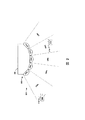
周囲環境のサウンドを検出するよう構成した複数のマイクロフォンは、複数の方向からくるサウンドを検出するように配置することができる。例えば、マイクロフォンをマイクロフォンの配列として配置することができる。図2は、マイクロフォンの配列202を有する例示的な着用可能な計算機システム200の概略を示す。特に、計算機システム200には、指向性マイクロフォン204a〜204eが含まれる。各指向性マイクロフォン204a〜204eは、それぞれ対応する領域206a〜206eのオーディオを捕捉するために配置されている。各指向性マイクロフォンは対応する領域から来るサウンドを主として検出するよう位置合わせされているが、このマイクロフォンは他の領域から来るサウンドも検出することがある。
The plurality of microphones configured to detect ambient sound can be arranged to detect sound coming from multiple directions. For example, microphones can be arranged as a microphone array. FIG. 2 shows a schematic of an exemplary
1つの実施例において、配列202したマイクロフォンは、図6に示したフレーム604、606、及び608のように、着用可能な計算機システムのフレームの様々な場所に沿って配置することができる。さらに、この配列202では、約150度の範囲の領域から来るサウンドを検出するよう配置しているが、他の例示的実施の形態による配列では、これ以上の角度(例えば、360度まで)又はそれ以下の角度の範囲の領域から来るサウンドを検出することができる。
In one embodiment, the arrayed microphones can be placed along various locations on the wearable computer system frame, such as
1つの実施例において、図2を参照して、着用可能な計算機システム200の周囲環境207には、サウンドの複数の音源を含めることができる。例えば、サウンド210の第1の音源208は、領域206aに位置し、サウンド214の第2の音源212は領域206dに位置することができる。着用可能な計算機システム200は、周囲環境のサウンドに対応するオーディオデータを受け取ることができる。特に、マイクロフォンの配列202により、サウンド210及びサウンド214を検出することができる。1つの実施例において、各マイクロフォンは、サウンド210及び214を検出することができる。マイクロフォンを配列202に配置することにより、各指向性マイクロフォン204a〜204eは、別々の時刻に及び/又は別々の強度レベルでサウンド210及び214を検出することができる。
B. オーディオデータの分析
周囲環境のサウンドを検出した後、着用可能な計算機システムは、図9に示したプロセッサー914のようなプロセッサーにオーディオデータを分析のために送ることができる。特に、着用可能な計算機システムは、ブロック104にて、(i)サウンドの音源の着用可能な計算機システムからの方向、及び、(ii)サウンドの強度レベル、の両方を測定するためにオーディオデータを分析する。
In one embodiment, referring to FIG. 2, the
B. Analysis of Audio Data After detecting the ambient sound, the wearable computer system can send the audio data for analysis to a processor, such as processor 914 shown in FIG. In particular, the wearable computer system obtains audio data at block 104 to measure both (i) the direction of the sound source from the wearable computer system and (ii) the sound intensity level. analyse.
サウンドの音源の着用可能な計算機システムからの方向を測定するために、着用可能な計算機システムは、マイクロフォン204a〜204eで集められたオーディオデータを分析することができる。上述のように、1つの実施例において、各マイクロフォンはサウンド210及びサウンド214を検出することができる。しかしながら各指向性マイクロフォン204a〜204eは、異なる時刻に及び/又は異なる強度レベルでサウンド210又は214を検出することができる。例えば、サウンド210は、サウンド210がマイクロフォン204b〜204eで検出されるより前に、マイクロフォン204aで検出されると思われる。同様に、サウンド214は、サウンド214が04a〜204c及び204eで検出されるより前に、マイクロフォン204dで検出されると思われる。種々のマイクロフォンでサウンドが検出される時間差に基づき、着用可能な計算機システムは、サウンドの音源の方向を測定することができる。このようなオーディオデータの方向分析は技術的にはよく知られている。配列202により検出されたオーディオデータに基づき、システムは、サウンド210の音源208は領域206aにあり、サウンド214の音源212は領域206dにあると判断することができる。
In order to determine the direction of the sound source from the wearable computer system, the wearable computer system can analyze the audio data collected by the
さらに、着用可能な計算機システムは、オーディオデータを分析して、サウンドの強度レベル(例えば、音量)を測定することができる。サウンドの強度レベルの測定は、技術的にはよく知られている。1つの実施例において、この強度レベルは、サウンドを特定した領域のマイクロフォンにより検出されたサウンドの強度レベルとすることができる。他の実施例において、この強度レベルは、配列中の各マイクロフォンが受け取ったサウンドの平均強度レベルとすることができる。 Furthermore, the wearable computer system can analyze the audio data to determine the intensity level (eg, volume) of the sound. The measurement of sound intensity level is well known in the art. In one embodiment, this intensity level may be the intensity level of the sound detected by the microphone in the area where the sound is identified. In other embodiments, this intensity level may be the average intensity level of the sound received by each microphone in the array.
周囲環境におけるサウンドの強度レベルは時間と共に変化することに注意しなければならない。例えば、音源208は人の話し声の可能性があり、ユーザの声は時間と共に変化することがある。他の例として、音源は、時間と共に強度が変化するサウンドを出力する楽器とすることができる。同様に、他の例も可能である。
It should be noted that the intensity level of the sound in the surrounding environment changes with time. For example, the
さらに、マイクロフォンは音源に近付くほど、多少は高い強度レベルでサウンドを記録すると思われるので、強度の測定を、サウンドの音源の方向を測定するための補助とすることができる。
C. (i)サウンドの音源の方向、及び、(ii)サウンドの強度レベルの、1以上の表示を着用可能な計算機システムに表示させる
オーディオデータの分析に応じて、着用可能な計算機システムは、ブロック106にて、サウンドの音源の方向、及び、サウンドの強度レベルを示す1以上の表示を行う。この1以上の表示は、周囲環境における役に立つサウンドに関する有益な情報をユーザに提供することができる。例えば、これらの表示は、周囲環境に存在するサウンドについて、耳の聞こえにくいユーザへの警報として役立たせることができる。他の例として、これらの表示は、耳の聞こえにくいユーザに、周囲環境がどのように聞こえているのかを視覚化することで手助けすることができる。
i. 単一のグラフィック表示
この1以上の表示は、(i)サウンドの音源の着用可能な計算機システムからの方向、及び、(ii)サウンドの強度レベルの両方を表示する単一のグラフィック表示を具備するようにできる。例えば、単一のグラフィック表示は矢印とすることができる。
In addition, the closer the microphone is to the sound source, the more likely it is that the sound will be recorded at a somewhat higher intensity level, so the intensity measurement can be an aid for measuring the direction of the sound source of the sound.
C. Depending on the analysis of the audio data, the wearable computer system may display the
i. Single Graphic Display The one or more displays comprise a single graphic display that displays both (i) the direction of the sound source from the wearable computer system and (ii) the sound intensity level. You can For example, a single graphic display can be an arrow.
図3aは、着用可能な計算機システム200の例示的ディスプレイ300の概略を示す。この実施例において、音源208は、ディスプレイ300の時のサウンドの音源のみである(すなわち、音源212はこのときサウンドを生じさせていない)。ディスプレイ300には、サウンド210の単一のグラフィック表示が含まれる。特に、図3aにおいて、サウンド210の音源208は人の話し声である。単一のグラフィック表示である矢印302は、(i)音源の着用可能な計算機システムからの方向、及び、(ii)の強度レベルの両方を表示している。この実施例では、矢印302はサウンドの音源の近くに配置されている。特に矢印302は、サウンドの音源の少し上に配置されている。矢印は、サウンドが来る方向に居るユーザを明確に示す役割を果たすことができる。他の例では、矢印は、音源の少し左または右、或いは音源208に重ねて配置することができる。
FIG. 3 a shows a schematic of an
上述の通り、サウンドの強度レベルは時間とともに変化する。従って、1つの実施例において、矢印の大きさは、強度レベルの変化に基づいて変化する。例えば、人の声は0デシベルから60デシベル(dB)までの範囲で変化することがある。矢印の大きさは、サウンド210の強度レベルに基づいて変化することができる。図3bはディスプレイ300に含まれることがある、例示的な矢印の大きさを示している。この実施例において、矢印310は、60dBに対応し、矢印312は、50dBに対応し、矢印314は、40dBに対応し、矢印316は、30dBに対応し、矢印318は、20dBに対応し、矢印320は、10dBに対応する。勿論、これらの間の他のデシベルレベルに対応する矢印を含めることもできる。大きな強度レベルに対し大きな矢印を表示することで、着用可能な計算機システムのユーザは、周囲環境に大きなサウンドが存在する時がわかる。1つの実施例において、周囲環境におけるサウンドが大きくなればなるほど、ユーザはサウンドにより注意を払ったり、サウンドをより認識すると思われる。従って、ユーザが表示された大きな矢印を見たとき、ユーザに対して、周囲環境に特別な注意を払うようディスプレイが表示することになる。
As described above, the sound intensity level changes with time. Thus, in one embodiment, the size of the arrow changes based on the change in intensity level. For example, a human voice can vary from 0 dB to 60 dB (dB). The size of the arrow can vary based on the intensity level of the
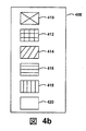
上述の通り、周囲環境中に2以上のサウンドの音源が存在することがある。従って、着用可能な計算機システムは、複数のサウンドの各々に対応するオーディオデータを受け取ることができ、このオーディオデータを分析して、(i)サウンドの各音源の着用可能な計算機システムからの方向、及び、(ii)各サウンドの強度レベルの両方を測定することができる。着用可能な計算機システムは、次いで、サウンドの方向、及び、サウンドの強度レベルを各サウンドについて表示するために、1以上の表示をディスプレイする。例えば、図4aに示すように、人208と人212が同時に話をしていることがある。図4aは、サウンド210の第1の表示402と、サウンド214の第2の表示404を含む例示的なディスプレイ400を表現している。この実施例において、表示はそれぞれの話し手の上にある円環となる。
As described above, there may be two or more sound sources in the surrounding environment. Accordingly, the wearable computer system can receive audio data corresponding to each of the plurality of sounds, and the audio data is analyzed to: (i) the direction of each sound source from the wearable computer system; And (ii) both intensity levels of each sound can be measured. The wearable computer system then displays one or more displays to display the direction of the sound and the intensity level of the sound for each sound. For example, as shown in FIG. 4a,
これらの円環は、両方ともサウンドの音源の方向を表すことができ、また、強度を表すこともできる。1つの実施例において、円環の大きさは、異なる強度に応じて変化することができる。しかしながら、別の例では、異なる色でサウンドの異なる強度レベルを表示することができる。例えば、円環は、強度レベルの変化を表示するために色コード化することができる。例えば、図4bは、異なる色コードのスケール408を表現している。この実施例において、色410は、60dBに対応し、色412は、50dBに対応し、色414は、40dBに対応し、色416は、30dBに対応し、色418は、20dBに対応し、色42010dBに対応する。1つの実施例において、より明るい色をより高い強度レベルに対応させることができる。
Both of these circles can represent the direction of the sound source, and can also represent the intensity. In one embodiment, the size of the annulus can vary according to different intensities. However, in another example, different intensity levels of sound can be displayed in different colors. For example, an annulus can be color coded to display intensity level changes. For example, FIG. 4 b represents different color code scales 408. In this example,
他の実施例として、強度の表示には、色コード化されたサウンドマップを含めることができる。例えば、図4cは、色コード化されたサウンドマップを有する例示的ディスプレイ450を示す。特に、サウンドの音源に対応するディスプレイの領域をサウンドの強度レベルを表示するように色付けすることができる。さらに、サウンドの音源に対応しないディスプレイの領域は、色付けしないでおくことができる(すなわち、ユーザが知覚するような自然な色のままにしておくことができる)。この実施例では、音源212は色412となっている一方、音源208は色416となっている。従って、ユーザは、音源212からのサウンドのほうが音源208からのサウンドより大きいことが分かる(すなわち、人212は人208より大きな声で話している)。
As another example, the intensity display may include a color coded sound map. For example, FIG. 4c shows an
さらに別の実施例として、例示的な単一のグラフィック表示では、サウンドの音源上に又は音源近くの点滅光とすることができる。点滅光の位置で、着用可能なコンピュータからの音源の方向を示すことができ、点滅光の周波数は、種々の強度レベルを示すために調整することができる。 As yet another example, an exemplary single graphic display can be a flashing light on or near a sound source. The position of the flashing light can indicate the direction of the sound source from the wearable computer, and the frequency of the flashing light can be adjusted to indicate various intensity levels.
別の実施例として、強度の表示には円形表示器が含まれる。例えば、グラフィックな表示器をサウンドの到着角度に対応して円形表示器の位置に置くことができる。さらに、円の中心からの距離をサウンドの強度レベルに対応させることができる。円形表示器は、例えば、全360度の到着角で捕捉できるシステムにおいて有用なものとすることができる。1つの実施例において、ディスプレイスクリーンの1つの隅のような、着用可能な計算機システムのディスプレイスクリーンの周辺に、円形表示器を表示することができる。 As another example, the intensity indication includes a circular indicator. For example, a graphic display can be placed at the position of a circular display corresponding to the angle of arrival of the sound. Furthermore, the distance from the center of the circle can correspond to the sound intensity level. A circular indicator can be useful, for example, in a system that can be captured with an arrival angle of all 360 degrees. In one embodiment, a circular indicator can be displayed around the display screen of the wearable computer system, such as one corner of the display screen.
図10a及び図10bは、例示的円形表示器を示す。特に図10aは、例示的円形表示器1000の概略を示す。円形表示器1000には、円1002及び強度表示バー1004が含まれる。この実施例では、強度表示バー1004の位置で、サウンドの音源が直接ユーザの後ろにあることを表示する役割を果たすことができる。さらに、円1002の中心1006からの強度表示バー1004の長さは、サウンドの強度レベルを表示する役割を果たすことができる。例えば、強度表示バーは、低い強度のサウンドに対して短くする(すなわち、中心から離れる)ことができ、強い強度のサウンドに対して長くする(すなわち、中心に近付く)ことができる。図10bは、円形表示器1010の他の実施例を示す。この実施例では、円形表示器には、円1012と強度表示バー1014とが含まれる。強度表示バー1014は、サウンドの音源がユーザの左にあることを表示する役割を果たす。さらに、強度表示バー1014の長さはサウンドの強度レベルを表示する。図10aに示されたサウンドの強度と比べて、図10bのサウンドの強度は弱い。
Figures 10a and 10b show an exemplary circular indicator. In particular, FIG. 10 a shows a schematic of an exemplary
1つの実施例において、強度表示バーを含めるのではなく、サウンドの強度を表示するために大きさを定めることができる矢印を円形表示器に含めることができる。さらに他の実施例において、円形表示器には、円の上に置いたグラフィック(例えば、点)を含めることができ、この点は、サウンドの強度に基づき色を変えることができる。当然のことながら、円形表示器には、サウンドの強度レベルを表示するために役立つ他のグラフィックを含めることができる。
ii. 方向及び強度の別々の表示
他の実施例において、この1以上の表示は、サウンドの音源の方向を示す第1の表示とサウンドの強度レベルを示す第2の表示とを具備する。例えば、第1の表示はサウンドの音源の方向を示す矢印又は円環とすることができ、第2の表示は強度メーター又は色コード化されたサウンドマップとすることができる。例示的強度メーター500を図5に示す。この実施例では、強度メーターは0デシベルから150デシベルの範囲であり、バー502は、サウンドの強度レベルを表示する(この例では、100dBである)。サウンドの強度レベルは時間とともに変化することがあり、従って、バー502の長さも強度レベルに合わせて変化することができる。
In one embodiment, rather than including an intensity display bar, the circular indicator can include an arrow that can be sized to display the intensity of the sound. In yet other embodiments, the circular indicator can include a graphic (eg, a dot) placed on the circle, which can change color based on the intensity of the sound. Of course, the circular indicator can include other graphics useful for displaying the intensity level of the sound.
ii. Separate indications of direction and intensity In another embodiment, the one or more indications comprise a first indication indicating the direction of the sound source of the sound and a second indication indicating the intensity level of the sound. For example, the first display can be an arrow or ring indicating the direction of the sound source, and the second display can be an intensity meter or a color coded sound map. An
強度メーター502のような強度メーターは、ディスプレイのいろいろな場所で表示することができる。例えば、強度メーターはディスプレイの周辺部に表示することができる。別の例では、強度メーターをサウンドの音源の近くに表示することができる。さらに、複数のサウンドの音源がある場合は、着用可能な計算機システムは、サウンドの音源毎に1つの強度メーターを表示させることができる。
iii. ユーザの視野外のサウンドの音源
1つの実施例において、サウンドの音源がユーザの視野の外側にあることがある。着用可能な計算機システムは、着用可能な計算機システムに約180度の現実世界の環境での視野範囲をもたらすことができる。着用可能な計算機システムは、周囲環境のこの視野の外側にある音源からくるサウンドを検出することができる。例えば、サウンドの音源は、ユーザの後ろ、又は、ユーザの周囲視覚範囲外における左又は右にあるかもしれない。着用可能な計算機システムは、サウンドの音源が視野の外側又は視野の周辺にあると判断することができる。1つの実施例において、着用可能な計算機システムには、マイクロフォンがどのような方向からのサウンドも(すなわち、360度の範囲で)検出できるように、着用可能な計算機システムのまわりに設置された複数のマイクロフォンを含めることができる。例えば、着用可能な計算機システムには、ユーザの頭のまわりに120度の間隔で、三角形に配置した3つのマイクロフォンを含めることができる。同様に、他のマイクロフォンを設置することも可能である。
An intensity meter, such as
iii. Sound source outside the user's field of view In one embodiment, the sound source may be outside the user's field of view. The wearable computer system can provide the wearable computer system with a field of view in a real world environment of about 180 degrees. A wearable computer system can detect sounds coming from sound sources outside this field of view of the surrounding environment. For example, the sound source may be behind the user or left or right outside the user's surrounding visual range. The wearable computer system can determine that the sound source is outside or around the field of view. In one embodiment, the wearable computer system includes a plurality of computers installed around the wearable computer system so that the microphone can detect sound from any direction (ie, in the range of 360 degrees). The microphone can be included. For example, a wearable computer system can include three microphones arranged in a triangle, spaced 120 degrees around the user's head. Similarly, other microphones can be installed.
表示の例として、視野の周辺で光を点滅させる点滅光とすることができる。例えば、ディスプレイには、ディスプレイ450の周辺部472の点470のように、ディスプレイの周辺部のいずれかの点に点滅光を含めることができる。この点滅光は、ユーザに対して、サウンドがユーザの視野外で検出されたことを表示する。
iv. 強度レベルの閾値を超えるサウンドの表示
1つの実施例において、この方法には、所定の閾値レベルを超える強度レベルに1以上の表示を着用可能な計算機システムに表示させるための、条件設定を伴うことができる。従って、周囲環境におけるサウンドの強度レベルを測定した後、着用可能な計算機システムは、この強度レベルが所定の閾値レベルを超えているかどうかを判断することができる。この強度レベルが所定の閾値レベルを超えている場合、着用可能な計算機システムは、前記1以上の表示を行う。しかし、強度レベルが所定の閾値レベルを超えていない場合、着用可能な計算機システムは、前記1以上の表示を行わない。
As an example of display, blinking light that blinks light around the visual field can be used. For example, the display can include flashing light at any point on the periphery of the display, such as
iv. Displaying Sounds Exceeding an Intensity Level Threshold In one embodiment, the method involves setting conditions to cause a wearable computer system to display one or more displays at an intensity level exceeding a predetermined threshold level. Can do. Therefore, after measuring the sound intensity level in the surrounding environment, the wearable computer system can determine whether this intensity level exceeds a predetermined threshold level. When the strength level exceeds a predetermined threshold level, the wearable computer system displays the one or more displays. However, if the strength level does not exceed the predetermined threshold level, the wearable computer system does not display the one or more displays.
この条件設定を行うステップは、例えば、ユーザが表示として見ることに関心を示さないであろう暗騒音を除外するのに有用である。1つの実施例において、着用可能な計算機システムは、5dBを超える強度レベルに1以上の表示を着用可能な計算機システムに表示させるよう条件設定する。他の閾値の例も可能であり、ユーザは、1dBと20dBとの間で閾値レベルを設定するとか、着用可能な計算機システムが望ましい閾値レベルを持つよう設定することができる。 This step of setting the condition is useful, for example, for excluding background noise that the user will not be interested in viewing as a display. In one embodiment, the wearable computer system is conditioned to cause the wearable computer system to display one or more displays at intensity levels greater than 5 dB. Other threshold examples are possible, and the user can set a threshold level between 1 dB and 20 dB, or the wearable computer system can have the desired threshold level.
他の実施例において、ユーザは、着用可能な計算機システムを着用することができ、この着用可能な計算機システムのディスプレイの電源を最初は停止状態にしておくことができる。例えば、ディスプレイを何らかの理由で停止状態にすることができる。しかしながら、ディスプレイが電源停止状態となっている間、着用可能な計算機システムはサウンドを検出することができる。このシステムはサウンドの強度レベルが所定の閾値レベルを超えているかどうかを判断することができる。強度レベルが所定の閾値レベルを超えているとの判断に対応して、システムは、1以上の表示を行わせるためにディスプレイを起動させることができる。
v. 移動平均窓に関連させて強度レベルを表示
1つの実施例において、サウンドの絶対強度を表示するのではなく、サウンド事象の強度レベル表示は、サウンド事象の絶対強度レベルと周囲環境のサウンドの移動平均窓の強度レベルとの差として代表させることができる。移動平均窓は、所定の継続時間を有する移動平均窓とすることができる。例えば、移動平均窓は、30秒とすることができる。勿論、移動平均窓は、これより長い、或いは、短い継続時間とすることができる。
In another embodiment, the user can wear a wearable computer system and the display of the wearable computer system can be initially turned off. For example, the display can be stopped for some reason. However, the wearable computer system can detect sound while the display is powered off. The system can determine whether the intensity level of the sound exceeds a predetermined threshold level. In response to determining that the intensity level exceeds a predetermined threshold level, the system can activate the display to cause one or more displays.
v. Displaying the intensity level in relation to the moving average window In one embodiment, rather than displaying the absolute intensity of the sound, the intensity level display of the sound event shows the absolute intensity level of the sound event and the moving average of the sound of the surrounding environment. It can be represented as the difference from the intensity level of the window. The moving average window may be a moving average window having a predetermined duration. For example, the moving average window can be 30 seconds. Of course, the moving average window can have a longer or shorter duration.
サウンド事象の絶対強度レベルと周囲環境のサウンドの移動平均窓の強度レベルとの差として、サウンド事象の強度レベルを代表させることにより、表示されるサウンドの強度は、ユーザの居る特定の環境に適合させることができる。このことは、ユーザの特別なサウンド環境での関連したサウンドをユーザに表示することの手助けとなる。例えば、着用可能な計算機システムのユーザが非常に静かな環境(例えば、空き部屋)にいる場合、直近30秒間の平均サウンド強度は低いと思われる。異常事象は、ドアを軽くノックする程度の静かなものである可能性がある。軽いノックのサウンドの強度は、直近30秒間の平均サウンド強度の比較的低いと思われるサウンド強度に対する相対値で表示することができる。 By representing the intensity level of the sound event as the difference between the absolute intensity level of the sound event and the moving average window intensity level of the sound in the surrounding environment, the intensity of the displayed sound is adapted to the specific environment where the user is located Can be made. This helps to display to the user related sounds in the user's special sound environment. For example, if the wearable computer system user is in a very quiet environment (eg, an empty room), the average sound intensity over the last 30 seconds may be low. An abnormal event can be as quiet as knocking the door lightly. The intensity of the light knock sound can be displayed as a relative value to the sound intensity that seems to be relatively low in the average sound intensity over the last 30 seconds.
一方、着用可能な計算機システムのユーザが非常にうるさい環境(例えば、騒音の多い工場)にいる場合、直近30秒間の平均サウンド強度は高くなる。サウンドの強度レベルは、この非常にうるさい環境のサウンドの平均強度に対する相対値で表示することができる。加えて、上述したように、いくつかの実施例では、着用可能な計算機システムは、所定の閾値を超えるサウンドの強度を表示するよう条件設定することができる。この所定の閾値は、平均ノイズの下限に基づくことができる。例えば、サウンドの強度を表示する条件を定める所定の閾値は、静かな環境に対してよりもうるさい環境に対してのほうを大きくすることができる。上記で説明した実施例を用いると、静かな環境では、平均ノイズの下限は、静かな部屋の平均ノイズに近い値に設定されることがある。一方、うるさい環境では、平均ノイズの下限は、騒音の多い工場の平均ノイズに近い値に設定されることがある。有利なことには、平均ノイズの下限に基づいて閾値レベルを調整することにより、着用可能な計算機システムは、ユーザが居る特定のサウンド環境に関連させてサウンドを確実に表示することができる。 On the other hand, if the wearable computer system user is in a very noisy environment (for example, a noisy factory), the average sound intensity over the last 30 seconds is high. The sound intensity level can be displayed relative to the average intensity of the sound in this very noisy environment. In addition, as described above, in some embodiments, the wearable computer system can be conditioned to display sound intensities that exceed a predetermined threshold. This predetermined threshold can be based on a lower limit of average noise. For example, the predetermined threshold that defines the condition for displaying the intensity of the sound can be larger for noisy environments than for quiet environments. Using the embodiments described above, in a quiet environment, the lower limit of average noise may be set to a value close to the average noise of a quiet room. On the other hand, in a noisy environment, the lower limit of the average noise may be set to a value close to the average noise of a noisy factory. Advantageously, by adjusting the threshold level based on the lower limit of average noise, the wearable computer system can reliably display the sound in relation to the particular sound environment in which the user is located.
1つの実施例において、着用可能な計算機システムは、この移動平均分析を連続的に稼働させるよう設定することができる。移動平均分析を連続的に稼働させることにより、ユーザは、ユーザが別のサウンド環境に(例えば、静かな環境からうるさい環境へ)移動したとき、手動で閾値レベルを変更する必要がない。
vi. サウンドの追加表示
着用可能な計算機システムからのサウンドの音源の方向及びサウンドの強度レベルの表示を行うのに加え、他のサウンド表示もまた可能である。上述したように、周囲環境でのサウンドは発話かもしれない。1つの実施例において、この方法はさらに、発話のテキストを定める発話からテキストへの変換特性を具備することができる。発話のテキストを決定した後、この方法は、着用可能な計算機システムに発話のテキストを表示させるステップを伴うことができる。1つの実施例において、着用可能な計算機システムは、話者の上に吹き出しを表示し、この吹き出しに話者の発話のテキストを記入しておくことができる。
In one embodiment, the wearable computer system can be configured to run this moving average analysis continuously. By running the moving average analysis continuously, the user does not need to manually change the threshold level when the user moves to another sound environment (eg, from a quiet environment to a noisy environment).
vi. In addition to displaying the sound source direction and sound intensity level from the wearable computer system, other sound displays are also possible. As mentioned above, sounds in the surrounding environment may be utterances. In one embodiment, the method may further comprise an utterance-to-text conversion characteristic that defines the text of the utterance. After determining the utterance text, the method may involve causing the wearable computer system to display the utterance text. In one embodiment, the wearable computer system can display a speech bubble over the speaker and write the speech text of the speaker in the speech bubble.
他のサウンド表示の可能性は、サウンドの音源が何であるかの表示である。1つの実施例において、着用可能な計算機システムは、サウンドの音源を判断することができ、着用可能な計算機システムサウンドの音源に関する情報を提供することができる。着用可能な計算機システムは、オーディオデータを分析し、サウンドの音源を判断することができ、そして、サウンドの音源を示す他の表示を行うことができる。例えば、この他の表示は、サウンドの音源について説明するテキスト表示(例えば、犬、猫、人、楽器、車、等)とすることができる。 Another sound display possibility is an indication of what the sound source is. In one embodiment, the wearable computer system can determine the sound source of the sound and can provide information about the sound source of the wearable computer system sound. The wearable computer system can analyze the audio data, determine the sound source, and make other displays that indicate the sound source. For example, this other display can be a text display (eg, dog, cat, person, instrument, car, etc.) describing the sound source.
例えば、着用可能な計算機システムは、サウンドの音源とサウンドとを一致させるためにサウンドを分析することができる。1つの実施例において、遠隔サーバーには、サウンドの断片のデータベースを含めることができ、各断片は音源と関連付けられている。サーバーは、検出したサウンドをサウンドの断片のデータベース中の種々のサウンドと比較し、合致するものを特定することができる。一旦、サウンドの音源を特定すると、着用可能な計算機システムは、その音源についての情報を表示する。例えば、音源を特定する情報を表示することができる。例えば、サウンドは、所定の車のエンジンからくるサウンドである可能性がある。着用可能な計算機システムは、それがどのような形式の車であるかを表示することができる。他の情報を提供することも可能である。例えば、着用可能な計算機システムは、その車の市場価格及び/又はその車を購入できる施設に関する情報を表示することができる。他の情報の例も可能である。 For example, a wearable computer system can analyze the sound to match the sound source to the sound. In one embodiment, the remote server can include a database of sound fragments, each fragment being associated with a sound source. The server can compare the detected sound with various sounds in the sound fragment database to identify matches. Once a sound source is identified, the wearable computer system displays information about the sound source. For example, information specifying a sound source can be displayed. For example, the sound may be a sound coming from a given car engine. A wearable computer system can display what type of car it is. Other information can also be provided. For example, the wearable computer system can display information about the market price of the car and / or the facilities where the car can be purchased. Other examples of information are possible.
他の実施例において、着用可能な計算機システムサウンドの音源に関するビデオを表示することができる。例えば、着用可能な計算機システムは岸辺からのサウンド(例えば、波の砕ける音)を検出することができる。着用可能な計算機システムは、岸辺と波の砕ける場面のビデオを表示することができる。このビデオは、その音を発している世界をユーザが視覚化する手助けをすることができる。 In another example, a video regarding the sound source of the wearable computer system sound can be displayed. For example, a wearable computer system can detect sound from the shore (eg, breaking waves). A wearable computer system can display a video of the shore and breaking waves. This video can help the user visualize the world that is producing the sound.
さらに他の実施例において、他の可能なサウンド表示は、サウンドのオーディオ周波数を示す表示である。オーディオ周波数は、例えば、音程を定めるサウンドの特性であり、オーディオ周波数は、ヘルツ(Hz)で測定することができる。一般に、普通の人の可聴周波数は、20Hzから20,000Hzである。しかし、個々の人が聞こえる周波数の範囲は周囲条件により影響されることがある。 In yet another embodiment, another possible sound display is a display showing the audio frequency of the sound. The audio frequency is, for example, a characteristic of the sound that defines the pitch, and the audio frequency can be measured in hertz (Hz). In general, the audible frequency of a normal person is 20 Hz to 20,000 Hz. However, the range of frequencies that an individual can hear can be affected by ambient conditions.
着用可能な計算機システムはサウンドを分析し、このサウンドのオーディオ周波数を様々な方法で測定することができる。例えば、着用可能な計算機システムは、周波数領域又は時間領域のどちらかのアルゴリズムを用いて、このサウンドのオーディオ周波数を分析することができる。前者では、入力信号の周波数変換における正弦波のピーク位置の特定を試みることがある。後者では、波形と時間遅れさせた波形との類似性を測定するために自己相関関数を用いることがある。サウンドのオーディオ周波数を測定した後、着用可能な計算機システムは、測定したオーディオ周波数表示を行うことができる。例えば、着用可能な計算機システムは、測定したオーディオ周波数の値を表示することができる。他の例として、着用可能な計算機システムは、オーディオ周波数の目盛を表示することができる。 A wearable computer system can analyze the sound and measure the audio frequency of this sound in various ways. For example, a wearable computer system can analyze the audio frequency of this sound using either frequency domain or time domain algorithms. The former may attempt to specify the peak position of the sine wave in the frequency conversion of the input signal. In the latter case, an autocorrelation function may be used to measure the similarity between the waveform and the time delayed waveform. After measuring the audio frequency of the sound, the wearable computer system can display the measured audio frequency. For example, a wearable computer system can display measured audio frequency values. As another example, a wearable computer system can display a scale of audio frequencies.
サウンドのオーディオ周波数を測定し、そのオーディオ周波数の表示を行うことは種々の理由で有益となる可能性がある。オーディオ周波数を視覚化することの利点の一例として、ユーザが高い周波数のノイズにさらされた状態で経験することができる。そのような状態では、高いオーディオ周波数の表示が表示されるので、サウンドが高いオーディオ周波数を持つことをユーザに警告することができる。この警告は、例えば、高いオーディオ周波数のサウンドに起因する潜在的な聴覚障害を回避する動作をユーザに取らせるよう誘導するのに役立つことがある。 Measuring the audio frequency of a sound and displaying that audio frequency can be beneficial for a variety of reasons. As an example of the benefits of visualizing audio frequencies, the user can experience being exposed to high frequency noise. In such a state, a display of a high audio frequency is displayed, so that the user can be warned that the sound has a high audio frequency. This warning may be useful, for example, to guide the user to take action to avoid potential hearing impairments due to high audio frequency sounds.
さらに別の実施例では、他の可能なサウンド表示は、ウィナーエントロピーを示す表示である。ウィナーエントロピーは、サウンドスペクトルの幾何平均の算術平均に対する割合として分析することができる。特に、ウィナーエントロピーは、0と1との間でサウンドの乱雑さの程度であり、そのサウンドがホワイトノイズなのか調和的なサウンドなのかを識別するために使うことができる。従って、着用可能な計算機システムのユーザ(例えば、聴覚障害を持つユーザ)は、サウンドがホワイトノイズなのか調和的なサウンドなのかを判断する利益を得ることができる。 In yet another embodiment, another possible sound display is a display showing winner entropy. The winner entropy can be analyzed as a ratio of the geometric mean of the sound spectrum to the arithmetic mean. In particular, the winner entropy is the degree of randomness of the sound between 0 and 1, and can be used to identify whether the sound is white noise or harmonic sound. Thus, a wearable computer system user (eg, a user with hearing impairments) can benefit from determining whether the sound is white noise or harmonic sound.
上述の例示的なサウンド表示に加えて、サウンドの他の表示も可能である。
III. 例示的システム及び装置
図6は、データを受信し、伝送し、表示するための例示的システム600の概略を示す。システム600は、着用可能な計算装置の形で示されている。システム600は、方法100を実行する構成とすることができる。図6が着用可能な計算装置の例として頭部装着装置602を図示するが、他の形式の着用可能な計算装置を付加的に又はもう1つの方法として用いることもできる。図6に示すように、頭部装着装置602は、レンズフレーム604,606及びフレームサポートセンター608を含むフレームエレメントと、レンズエレメント610,612と、突き出たサイドアーム614,616とを具備する。フレームサポートセンター608及び突き出たサイドアーム614,616は、それぞれユーザの鼻と耳を介してユーザの顔に頭部装着装置602を固定するよう構成されている。
In addition to the exemplary sound display described above, other displays of sound are possible.
III. Exemplary System and Apparatus FIG. 6 shows an overview of an
フレームエレメント604,606及び608及び、突き出たサイドアーム614,616は、プラスチック及び/又は金属の中空でない構造で形成することができ、又は、頭部装着装置602の内部を通り抜けて配線し部品の相互接続するように、同様の材料で中空構造に形成することができる。他の材料も可能である。
The
レンズエレメント610,612の各々1以上は、投影された画像又はグラフィックを適切に表示することができるどのような材料で形成してもよい。レンズエレメント610,612の各々は、ユーザがこのレンズエレメントを通して見ることができるよう十分透明にすることができる。レンズエレメントのこれらの2つの特性を結合させることにより、投影された画像又はグラフィックがレンズエレメントを通してユーザが知覚する現実世界の光景に重ねあわされた、迫真性を増大させた表示又はヘッドアップ表示を容易にする。
Each one or more of the
突き出たサイドアーム614,616は、それぞれレンズフレーム604,606から伸びる突出部とすることができ、ユーザの耳の後ろに位置して頭部装着装置602をユーザに固定することができる。突き出たサイドアーム614,616は、さらに、ユーザの頭の後部にまで伸ばすことにより頭部装着装置602をユーザに固定することができる。加えて、又は、もう1つの方法として、例えば、システム600は、頭部に装着するヘルメットの機構の中に結合又は固定することができる。他の可能性も存在する。
The protruding
システム600には、オンボード計算機システム618、ビデオカメラ620、センサー622、及び、指操作可能なタッチパッド624も含めることができる。オンボード計算機システム618は、頭部装着装置602の突き出たサイドアーム614上に示されている。しかしながら、オンボード計算機システム618は、頭部装着装置602の他の部分に取り付けることが可能であり、或いは、頭部装着装置602から離れて設置することも可能である(例えば、オンボード計算機システム618は、頭部装着装置602と有線又は無線で接続することができる)。オンボード計算機システム618には、例えば、プロセッサー及びメモリーを含めることができる。オンボード計算機システム618は、ビデオカメラ620及び指操作可能なタッチパッド624から(及び、他の知覚装置、又は、ユーザインターフェース、又は、その両方から)のデータを受け取り分析し、画像を生成してレンズエレメント610及び612により出力するよう構成することができる。
The
ビデオカメラ620は、頭部装着装置602の突き出たサイドアーム614上に示されている。しかしながら、ビデオカメラ620は、頭部装着装置602の他の部分に取り付けることが可能である。ビデオカメラ620は、種々の解像度又は異なるフレームレートで画像をとらえるよう構成することができる。例えば、携帯電話やウェブカメラで用いられるような小さなフォームファクタの多くのビデオカメラをシステム600の実施例に組む込むことができる。
さらに、図6は1つのビデオカメラ620を示しているが、1以上のビデオカメラを用いることもでき、各々のカメラで同じ光景をとらえるようにすることも、異なる光景をとらえるようにすることも可能である。例えば、ビデオカメラ620はユーザが知覚する現実世界の光景の少なくとも一部をとらえるように前方に向けることができる。この前方に向けたビデオカメラ620でとらえた画像は、次に、コンピュータ生成された画像が、ユーザが知覚する現実世界の光景と互いに影響しあうようにして、迫真性を増大させるために用いることができる。
Furthermore, although FIG. 6 shows one
センサー622は、頭部装着装置602の突き出たサイドアーム616上に示されている。しかしながら、センサー622は、頭部装着装置602の他の部分に取り付けることが可能である。センサー622には、例えば、1以上のジャイロスコープ又は加速度計を含めることができる。他の検知装置このセンサー622内に又はこのセンサー622に加えて含めることができ、或いは、他の検知機能をセンサー622が果たすことができる。
指操作可能なタッチパッド624は、頭部装着装置602の突き出たサイドアーム616上に示されている。しかしながら、指操作可能なタッチパッド624は、頭部装着装置602の他の部分に取り付けることが可能である。また、2以上の指操作可能なタッチパッドが部装着装置602上にあってもよい。指操作可能なタッチパッド624はユーザにより命令を入力するために使うことができる。指操作可能なタッチパッド624は、いろいろな可能性の中で、静電容量検出、抵抗検出、表面弾性波処理により、指の位置及び動きの少なくとも1つを検知することができる。指操作可能なタッチパッド624は、パッド表面と平行又は平面的な方向、パッド表面と垂直な方向、又はその両方の方向への指の動きを検出することができ、また、パッド表面に加わる圧力のレベルを検出することもできる。指操作可能なタッチパッド624は、1以上の半透明な又は透明な絶縁層、及び、1以上の半透明な又は透明な導電層により形成することができる。指操作可能なタッチパッド624の端部は、ユーザの指が指操作可能なタッチパッド624の端部又は他の領域に触れたとき、ユーザに触覚的に手ごたえを与えるため、隆起した表面、又はぎざぎざにした表面、又は、粗い表面で形成することができる。2以上の指操作可能なタッチパッドがある場合は、指操作可能なタッチパッドの各々を独立に動作させることができ、異なる機能を与えることができる。
A finger
図7は、図6に概略的に示したシステム600を別の視点から見たものである。図7に示すように、レンズエレメント610,612は、ディスプレイエレメントとしての役割を果たすことができる。頭部装着装置602には、突き出たサイドアーム616の内側面に取り付けられ、レンズエレメント612の内側面にディスプレイ630を投影するよう構成された、第1のプロジェクター628を含めることができる。加えて、又は、もう1つの方法として、第2のプロジェクター632を突き出たサイドアーム614内側面に取り付け、レンズエレメント610の内側面にディスプレイ634を投影するよう構成することができる。
FIG. 7 is a view of the
レンズエレメント610,612は、光投影システムにおけるコンバイナとしての役割を果たすことができ、プロジェクター628,632から投影された光を反射するコーティングを含めることができる。実施の形態によっては、反射コーティングを用いない場合もある(例えば、プロジェクター628,632がスキャニングレーザ装置であるとき)。
The
代替的実施の形態において、他の形式のディスプレイエレメントを用いることもできる。例えば、レンズエレメント610,612自身には、エレクトロルミネッセントディスプレイ又は液晶ディスプレイのような透明又は半透明なマトリックスディスプレイ、画像をユーザの目に送る1以上の導波路、或いは、目の近くに焦点を合わせた画像をユーザに送ることができる他の光エレメントを含めることができる。対応するディスプレイドライバは、このようなマトリックスディスプレイを駆動するためにフレームエレメント604,606内に取り付けることができる。もう1つの方法として、又は、付加的に、レーザ又はLED源、及び、スキャニングシステムを1以上のユーザの目の網膜上に直接ラスターディスプレイを描画するために用いることができる。同様に、他の可能性も存在する。
In alternative embodiments, other types of display elements can be used. For example, the
図8aは、データを受信し、伝送し、表示するための例示的システム800の概略を示す。システム800は、方法100を実行するために構成されている。システム800は、着用可能な計算装置802の形で示されている。着用可能な計算装置802には、図6及び図7を参照して説明したような、フレームエレメント及びサイドアームが含まれる。着用可能な計算装置802は、図6及び図7を参照して説明したような、オンボード計算機システム804とビデオカメラ806とを付加的に含めることができる。ビデオカメラ806は、着用可能な計算装置802のフレームに取り付けられているのが示されているが、ビデオカメラ806は、他の位置に取り付けることもできる。
FIG. 8a shows an overview of an
図8aに示すように、着用可能な計算装置802には、装置に取り付けることのできる1つのディスプレイ808を含めることができる。ディスプレイ808は、図6及び図7を参照して説明したレンズエレメントのような、着用可能な計算装置802のレンズエレメントの1つに形成することができ、ユーザの現実の世界の光景にコンピュータ生成されたグラフィックスを重ね合わせるよう構成することができる。ディスプレイ808は、着用可能な計算装置802のレンズの中央に取り付けるよう示されているが、ディスプレイ808は、他の場所に取り付けることもできる。ディスプレイ808は、光導波路810を介してディスプレイ808と接続されている計算機システム804により制御することができる。
As shown in FIG. 8a, the
図8bは、データを受信し、伝送し、表示するための例示的システム820の概略を示す。システム820は、方法100を実行するために構成されている。システム820は、着用可能な計算装置822の形で示されている。着用可能な計算装置822には、サイドアーム823、中央フレームサポート824、及び鼻あて825の付いたブリッジ部を含めることができる。図8bに示した実施例では、中央フレームサポート824は、サイドアーム823とつながっている。着用可能な計算装置822には、レンズエレメントを有するレンズフレームが含まれていない。着用可能な計算装置822には、図6及び図7を参照して説明したような、オンボード計算機システム826及びビデオカメラ828を付加的に含めることができる。
FIG. 8b shows a schematic of an
着用可能な計算装置822には、サイドアーム823又は中央フレームサポート824のうちの1つに取り付けられた1つのレンズエレメント830を含めることができる。レンズエレメント830には、図6及び図7を参照して説明したような、ディスプレイを含めることができ、ユーザの現実の世界の光景にコンピュータ生成されたグラフィックスを重ね合わせるよう構成することができる。1つの実施例では、1つのレンズエレメント830が、突き出たサイドアーム823の内側(ユーザが装着したときにユーザの頭に曝される側)に取り付けることができる。1つのレンズエレメント830は、着用可能な計算装置822をユーザが装着したときにユーザの目の前、又は目の近傍に配置することができる。例えば、1つのレンズエレメント830は、図8bに示すように、中央フレームサポート824の下に配置することができる。
The
図9は、コンピュータネットワークのインフラ基盤の概略図を示す。システム900において、装置910は通信リンク920(例えば、有線接続又は無線接続)を用いて、遠隔装置930と通信する。装置910は、データを受け取り、そのデータに対応する情報又はそのデータに関連する情報を表示することのできるどのような形式の装置でもよい。例えば、装置910は、図6〜図8bを参照して説明した頭部装着装置602,800,又は820のような、ヘッドアップディスプレイシステムとすることができる。
FIG. 9 shows a schematic diagram of the infrastructure of a computer network. In
従って、装置910には、プロセッサー914及びディスプレイ916を具備するディスプレイシステム912を含めることができる。ディスプレイ910は、例えば、光学的なシースルーディスプレイ、光学的なシーアラウンドディスプレイ、又は、ビデオシースルーディスプレイとすることができる。プロセッサー914は、遠隔装置930からのデータを受け取り、ディスプレイ916上にこのデータを表示するよう構成することができる。プロセッサー914は、例えば、マイクロプロセッサー又はディジタル信号プロセッサーのような、どのような形式のプロセッサーでもよい。
Accordingly, the
装置910にはさらに、プロセッサー914と接続されたメモリー918のような、オンボードデータ記憶装置を含めることができる。メモリー918は、例えば、プロセッサー914からアクセスすることができ、プロセッサー914で実行することができるソフトウェアを保存することができる。
The
遠隔装置930は、データを装置910に送るよう構成したラップトップコンピュータ、携帯電話、又はタブレット計算装置、等、を含む、任意の形式の計算装置又は伝送器とすることができる。遠隔装置930及び装置910は、プロセッサー、伝送器、受信器、アンテナ、等、のような、通信リンク920を可能とするハードウェアを有することができる。
The
図9において、通信リンク920は、無線接続として示されているが、有線接続も用いることができる。例えば、通信リンク920は、ユニバーサルシリアルバスのような有線シリアルバス又はパラレルバスとすることができる。有線接続は独自の接続としてもよい。通信リンク920はまた、他の可能性の中でも、例えばブルートゥース(登録商標)、無線技術、IEEE802.11に記載された通信プロトコル(IEEE802.11改訂版を含む)、(GSM、CDMA、UMTS、EVDO、WiMAX、又はLTEのような)携帯電話技術、Zigbee(登録商標)技術を用いた無線接続とすることもできる。遠隔装置330は、インターネットを介してアクセスすることができ、特定のウェブサービス(例えば、ソーシャルネットワーキング、フォトシェアリング、アドレスブック、等)と関連させたコンピューティングクラスターを含むことができる。
In FIG. 9, the
図9を参照して、装置910は方法100のステップを実行することができる。特に、この方法100は、一時的ではないコンピュータ読み取り可能媒体に保存された命令を実行したとき、プロセッサー914により実行される動作に対応している。1つの実施例において、一時的ではないコンピュータ読み取り可能媒体は、メモリー918の一部とすることができる。この一時的ではないコンピュータ読み取り可能媒体は、プロセッサー914による動作に応答して、プロセッサー914に種々の動作を行わせる命令を、この媒体に保存しておくことができる。この命令には、(a)着用可能な計算機システムが検出したサウンドに対応するオーディオデータを受け取る命令と、(b)このオーディオデータを分析し、(i)このサウンドの音源のこの着用可能な計算機システムからの方向、及び、(ii)このサウンドの強度レベル、の両方を測定する命令と、(c)この着用可能な計算機システムに、(i)このサウンドの音源の方向、及び、(ii)このサウンドの強度レベル、の1以上の状態を表示させる命令と、が含まれる。さらに、1つの実施例において、この命令にはさらに、この着用可能な計算機システムに所定の閾値レベルを超えた強度レベルを有する1以上の状態を表示させるための条件を設定する命令が含まれる。
IV. 結論
当然のことながら、ここに記載の構成は、単なる実施例である。従って、当業者であれば他の構成又は他のエレメント(例えば、機械、インターフェース、機能、順序、及び機能のグループ分け、等)を用いることができること、及び、いくつかのエレメントは省略しても所望の結果が得られることを理解するであろう。さらに、ここに記載のエレメントの多くは、別々の又は分散した構成部品として、又は任意の組み合わせ及び場所で他の構成部品と組み合わせて、実行することのできる、機能的存在として記述している。
With reference to FIG. 9,
IV. CONCLUSION Naturally, the configuration described here is merely an example. Thus, one skilled in the art can use other configurations or other elements (eg, machines, interfaces, functions, sequences, and functional groupings, etc.) and omit some elements. It will be appreciated that the desired result is obtained. Further, many of the elements described herein are described as functional entities that can be implemented as separate or distributed components, or in combination with other components in any combination and location.
当然のことながら、ここに記載のシステム及び方法が、ユーザに関する個人情報、又はユーザの個人情報にかかわる情報を収集し及び/又は用いる場合、そのユーザには、そのような個人情報(例えば、ユーザの嗜好に関する情報)を含有するプログラム又は特徴を選択/除外する機会を与えることができる。加えて、個人を特定することができる情報を除去するために、特定のデータを、保存または使用する前に1以上の方法で匿名化することができる。例えば、個人を特定する情報をユーザ特定のために使えなくするために、そして、あらゆるユーザの嗜好又はユーザの相互関係を、特定のユーザと関連付けないで、一般化するために(例えば、ユーザの人口統計に基づいて一般化するために)、ユーザの身元は匿名化することができる。 Of course, if the systems and methods described herein collect and / or use personal information about the user or information relating to the user's personal information, the user may receive such personal information (eg, user Can be given the opportunity to select / exclude programs or features that contain (information about preferences). In addition, specific data can be anonymized in one or more ways before being stored or used in order to remove personally identifiable information. For example, to make personally identifiable information unavailable for user identification, and to generalize any user preferences or user interrelationships without associating them with specific users (eg, user To generalize based on demographics), the identity of the user can be anonymized.
多くの特徴及び実施の形態をここに開示したが、他の特徴及び実施の形態が可能なことは当業者には明らかである。ここに開示した種々の特徴及び実施の形態は図解のためのものであり、限定を意図するものではなく、実際の権利範囲は以下の特許請求の範囲によって示されるものであり、特許請求の範囲で示したような範囲と均等なものも含まれる。当然のことながら、ここに記載の用語の言い回しも特定の実施の形態を説明するためだけのものであり、限定のためのものではない。 While many features and embodiments have been disclosed herein, it will be apparent to those skilled in the art that other features and embodiments are possible. The various features and embodiments disclosed herein are for purposes of illustration and are not intended to be limiting, the actual scope of which is indicated by the following claims, and the claims Those equivalent to the range shown in the above are also included. It will be appreciated that the terminology used herein is for the purpose of describing particular embodiments only and is not intended to be limiting.
Claims (19)
着用可能な計算機システムが検出したサウンドに対応するオーディオデータを受け取るステップであって、前記着用可能な計算機システムは、前記着用可能な計算機システムにおける現実世界の環境での視野をもたらす、ステップと、
前記オーディオデータを分析し、(i)前記サウンドの音源の前記着用可能な計算機システムからの方向、及び、(ii)前記サウンドの強度レベル、の両方を測定するステップと、
前記音源が、前記視野の外側又は前記視野の周辺にあると判断するステップと、
前記着用可能な計算機システムに、(i)前記サウンドの音源の方向、及び、(ii)前記サウンドの強度レベル、を示す1以上の表示を行うステップと、
を具備し、
前記1以上の表示として、前記視野の周辺にある点滅光を具備し、
前記着用可能な計算機システムは、前記着用可能な計算機システムに所定の閾値レベルを超えた強度レベルを有する1以上の表示を行うための条件設定を行うことを特徴とする、
方法。 A method performed by a computer,
Receiving audio data corresponding to sound detected by the wearable computer system, wherein the wearable computer system provides a view in a real-world environment on the wearable computer system ;
Analyzing the audio data and measuring both (i) the direction of the sound source from the wearable computer system and (ii) the intensity level of the sound;
Determining that the sound source is outside or around the field of view;
Displaying on the wearable computer system one or more of (i) the direction of the sound source of the sound and (ii) the intensity level of the sound;
Comprising
As the one or more displays, comprising flashing light around the visual field,
The wearable computer system is characterized in that the wearable computer system performs a condition setting for performing one or more displays having an intensity level exceeding a predetermined threshold level.
Method.
前記強度レベルを測定した後、前記強度レベルが所定の閾値レベルを超えているかどうかを判断するステップと、
前記強度レベルが前記所定の閾値レベルを超えているとの判断に対応して、前記1以上の表示を行うために前記ディスプレイを起動させるテップと、
を具備することを特徴とする、請求項1に記載の方法。 The wearable computer system display is initially powered down, and the method includes:
After measuring the intensity level, determining whether the intensity level exceeds a predetermined threshold level;
In response to determining that the intensity level exceeds the predetermined threshold level, a step of activating the display to perform the one or more displays;
The method of claim 1, comprising:
前記発話のテキストを決定する、発話からテキストへの変換特性決定ステップと、
前記発話のテキストを前記着用可能な計算機システムに表示するステップと、
を具備することを特徴とする請求項1に記載の方法。 The sound comprises an utterance, and the method further comprises:
An utterance-to-text conversion characteristic determination step for determining the text of the utterance;
Displaying the utterance text on the wearable computer system;
The method of claim 1, comprising:
前記オーディオデータを分析し、(i)前記第2のサウンドの音源の前記着用可能な計算機システムからの方向であって、前記第2のサウンドの方向は前記サウンドの方向とは異なることを特徴とする方向、及び、(ii)前記第2のサウンドの強度レベル、の両方を測定するステップと、
前記着用可能な計算機システムに、(i)前記第2のサウンドの音源の方向、及び、(ii)前記2のサウンドの強度レベル、の1以上の表示を行うステップと、
を具備することを特徴とする請求項1に記載の方法。 Receiving audio data corresponding to a second sound detected by the wearable computer system;
Analyzing the audio data; and (i) a direction of the second sound source from the wearable computer system, wherein the direction of the second sound is different from the direction of the sound. Measuring both the direction of playing and (ii) the intensity level of the second sound;
Displaying one or more of (i) the direction of the sound source of the second sound and (ii) the intensity level of the second sound on the wearable computer system;
The method of claim 1, comprising:
前記着用可能な計算機システムに、他の表示を行うステップであって、前記他の表示は、前記サウンドの音源を示す他の表示であることを特徴とするステップと、
をさらに具備することを特徴とする請求項1に記載の方法。 Analyzing the audio data to measure the direction of the sound source of the sound;
A step of performing another display on the wearable computer system, wherein the other display is another display indicating a sound source of the sound; and
The method of claim 1, further comprising:
着用可能な計算機システムが検出したサウンドに対応するオーディオデータを受け取るステップと、
前記オーディオデータを分析し、(i)前記サウンドの音源の前記着用可能な計算機システムからの方向、及び、(ii)前記サウンドの強度レベル、の両方を測定するステップと、
前記着用可能な計算機システムに、(i)前記サウンドの音源の方向、及び、(ii)前記サウンドの強度レベル、を示す1以上の表示を行うステップと、
を具備し、
前記着用可能な計算機システムは、前記着用可能な計算機システムに所定の閾値レベルを超えた強度レベルを有する1以上の表示を行うための条件設定を行い、
前記サウンドの音源の方向を測定するために前記オーディオデータを分析するステップと、
前記着用可能な計算機システムに、他の表示を行うステップであって、前記他の表示は、前記サウンドの音源を示す他の表示であり、前記他の表示は、前記サウンドの音源に関するビデオである、ステップとをさらに具備することを特徴とする方法。 A method performed by a computer,
Receiving audio data corresponding to the sound detected by the wearable computer system;
Analyzing the audio data and measuring both (i) the direction of the sound source from the wearable computer system and (ii) the intensity level of the sound;
Displaying on the wearable computer system one or more of (i) the direction of the sound source of the sound and (ii) the intensity level of the sound;
Comprising
The wearable computer system performs a condition setting for performing one or more displays having an intensity level exceeding a predetermined threshold level on the wearable computer system,
Analyzing the audio data to measure the direction of the sound source of the sound;
The other display on the wearable computer system, wherein the other display is another display showing the sound source of the sound, and the other display is a video relating to the sound source of the sound. And a step .
着用可能な計算機システムが検出したサウンドに対応するオーディオデータを受け取る命令と、
前記オーディオデータを分析し、(i)前記サウンドの音源の前記着用可能な計算機システムからの方向、及び、(ii)前記サウンドの強度レベル、の両方を測定する命令と、
前記着用可能な計算機システムに、(i)前記サウンドの音源の方向、及び、(ii)前記サウンドの強度レベル、の1以上の表示を行う命令と、
を具備し、
前記着用可能な計算機システムに1以上の表示を行わせる命令の設定条件は、前記強度レベルが所定の閾値レベルを超えていることであり、
前記着用可能な計算機システムは、前記着用可能な計算機システムにおける現実世界の環境での視野をもたらし
前記命令は、前記音源が前記視野の外側又は前記視野の周辺にあると判断する命令をさらに具備し、前記1以上の表示として、前記視野の周辺にある点滅光を具備する、
一時的ではないコンピュータ読み取り可能媒体。 A non-transitory computer readable medium having instructions that cause a processor to operate in response to execution by a processor, the instructions comprising:
Instructions to receive audio data corresponding to the sound detected by the wearable computer system;
Instructions to analyze the audio data and (i) measure both the direction of the sound source from the wearable computer system and (ii) the intensity level of the sound;
Instructions to the wearable computer system to display one or more of: (i) the direction of the sound source of the sound; and (ii) the intensity level of the sound;
Comprising
Setting conditions of instructions to perform one or more displayed on the wearable computer system is that the intensity level is above a predetermined threshold level,
The wearable computer system provides a field of view in a real world environment on the wearable computer system and the instructions further comprise instructions for determining that the sound source is outside or around the field of view. The flashing light around the field of view as the one or more displays;
A non-transitory computer readable medium.
頭部装着ディスプレイであって、前記頭部装着ディスプレイは、コンピュータで生成された情報を表示するよう構成され、現実世界の環境を視覚的に知覚することを可能にすることを特徴とする頭部装着ディスプレイと、
コントローラであって、前記コントローラは、着用可能な計算機システムが検出したサウンドに対応するオーディオデータを受け取り、(i)前記サウンドの音源の前記着用可能な計算機システムからの方向、及び、(ii)前記サウンドの強度レベル、の両方を測定するよう構成されていることを特徴とするコントローラと、
ディスプレイシステムであって、前記ディスプレイシステムは、(i)前記音源の方向、び、(ii)前記強度レベル、を示す1以上の表示を行うよう構成されていることを特徴とするディスプレイシステムと、
を具備し、
前記コントローラは、前記着用可能な計算機システムに所定の閾値レベルを超えた強度レベルを有する1以上の表示を行うための条件設定を行うよう構成されており、
前記着用可能な計算機システムは、前記着用可能な計算機システムにおける現実世界の環境での視野をもたらし、前記音源が前記視野の外側又は前記視野の周辺にあると判断し、
前記1以上の表示として、前記視野の周辺にある点滅光を具備する、ことを特徴とする、
着用可能な計算機システム。 A wearable computer system,
A head-mounted display, wherein the head-mounted display is configured to display information generated by a computer, and enables visual perception of a real-world environment. An attached display;
A controller, which receives audio data corresponding to the sound detected by the wearable computer system; (i) a direction of the sound source from the wearable computer system; and (ii) the A controller that is configured to measure both the intensity level of the sound; and
A display system, wherein the display system is configured to display one or more of (i) the direction of the sound source and (ii) the intensity level; and
Comprising
The controller is configured to set a condition for performing one or more displays having an intensity level exceeding a predetermined threshold level on the wearable computer system ;
The wearable computer system provides a field of view in the real-world environment of the wearable computer system and determines that the sound source is outside or around the field of view;
The one or more displays include flashing light around the field of view ,
Wearable computer system.
前記コントローラは、前記強度レベルを測定した後、前記強度レベルが所定の閾値レベルを超えているかどうかを判断し、
前記ディスプレイシステムは、前記強度レベルが前記所定の閾値レベルを超えているとの判断に対応して、前記1以上の表示を行うために前記ディスプレイを起動させる、
ことを特徴とする請求項18に記載の着用可能な計算機システム。 The display system display is initially powered down,
The controller, after measuring the intensity level, determines whether the intensity level exceeds a predetermined threshold level;
The display system activates the display to perform the one or more displays in response to determining that the intensity level exceeds the predetermined threshold level;
The wearable computer system according to claim 18 .
Applications Claiming Priority (3)
| Application Number | Priority Date | Filing Date | Title |
|---|---|---|---|
| US13/295,953 US8183997B1 (en) | 2011-11-14 | 2011-11-14 | Displaying sound indications on a wearable computing system |
| US13/295,953 | 2011-11-14 | ||
| PCT/US2012/060342 WO2013074234A1 (en) | 2011-11-14 | 2012-10-16 | Displaying sound indications on a wearable computing system |
Publications (2)
| Publication Number | Publication Date |
|---|---|
| JP2015510283A JP2015510283A (en) | 2015-04-02 |
| JP5881263B2 true JP5881263B2 (en) | 2016-03-09 |
Family
ID=46061263
Family Applications (1)
| Application Number | Title | Priority Date | Filing Date |
|---|---|---|---|
| JP2014541077A Active JP5881263B2 (en) | 2011-11-14 | 2012-10-16 | Display of sound status on wearable computer system |
Country Status (6)
| Country | Link |
|---|---|
| US (3) | US8183997B1 (en) |
| EP (1) | EP2780757A4 (en) |
| JP (1) | JP5881263B2 (en) |
| KR (1) | KR101668165B1 (en) |
| CN (1) | CN103946733B (en) |
| WO (1) | WO2013074234A1 (en) |
Families Citing this family (142)
| Publication number | Priority date | Publication date | Assignee | Title |
|---|---|---|---|---|
| US8917876B2 (en) | 2006-06-14 | 2014-12-23 | Personics Holdings, LLC. | Earguard monitoring system |
| US20080031475A1 (en) | 2006-07-08 | 2008-02-07 | Personics Holdings Inc. | Personal audio assistant device and method |
| US11450331B2 (en) | 2006-07-08 | 2022-09-20 | Staton Techiya, Llc | Personal audio assistant device and method |
| WO2008091874A2 (en) | 2007-01-22 | 2008-07-31 | Personics Holdings Inc. | Method and device for acute sound detection and reproduction |
| US8254591B2 (en) | 2007-02-01 | 2012-08-28 | Personics Holdings Inc. | Method and device for audio recording |
| US11750965B2 (en) | 2007-03-07 | 2023-09-05 | Staton Techiya, Llc | Acoustic dampening compensation system |
| WO2008124786A2 (en) | 2007-04-09 | 2008-10-16 | Personics Holdings Inc. | Always on headwear recording system |
| US11317202B2 (en) | 2007-04-13 | 2022-04-26 | Staton Techiya, Llc | Method and device for voice operated control |
| US11683643B2 (en) | 2007-05-04 | 2023-06-20 | Staton Techiya Llc | Method and device for in ear canal echo suppression |
| US10194032B2 (en) | 2007-05-04 | 2019-01-29 | Staton Techiya, Llc | Method and apparatus for in-ear canal sound suppression |
| US11856375B2 (en) | 2007-05-04 | 2023-12-26 | Staton Techiya Llc | Method and device for in-ear echo suppression |
| WO2008139018A1 (en) * | 2007-05-09 | 2008-11-20 | Savox Communications Oy Ab (Ltd) | A display apparatus |
| US10009677B2 (en) | 2007-07-09 | 2018-06-26 | Staton Techiya, Llc | Methods and mechanisms for inflation |
| ITUD20070127A1 (en) * | 2007-07-16 | 2009-01-17 | Eurotech S P A | WEARABLE ELECTRONIC EQUIPMENT |
| US8600067B2 (en) | 2008-09-19 | 2013-12-03 | Personics Holdings Inc. | Acoustic sealing analysis system |
| US9129291B2 (en) | 2008-09-22 | 2015-09-08 | Personics Holdings, Llc | Personalized sound management and method |
| US8554350B2 (en) | 2008-10-15 | 2013-10-08 | Personics Holdings Inc. | Device and method to reduce ear wax clogging of acoustic ports, hearing aid sealing system, and feedback reduction system |
| US9138353B2 (en) | 2009-02-13 | 2015-09-22 | Personics Holdings, Llc | Earplug and pumping systems |
| US20150309316A1 (en) | 2011-04-06 | 2015-10-29 | Microsoft Technology Licensing, Llc | Ar glasses with predictive control of external device based on event input |
| US8472120B2 (en) | 2010-02-28 | 2013-06-25 | Osterhout Group, Inc. | See-through near-eye display glasses with a small scale image source |
| US11275482B2 (en) * | 2010-02-28 | 2022-03-15 | Microsoft Technology Licensing, Llc | Ar glasses with predictive control of external device based on event input |
| US20120249797A1 (en) | 2010-02-28 | 2012-10-04 | Osterhout Group, Inc. | Head-worn adaptive display |
| WO2011106798A1 (en) | 2010-02-28 | 2011-09-01 | Osterhout Group, Inc. | Local advertising content on an interactive head-mounted eyepiece |
| US8482859B2 (en) | 2010-02-28 | 2013-07-09 | Osterhout Group, Inc. | See-through near-eye display glasses wherein image light is transmitted to and reflected from an optically flat film |
| US8467133B2 (en) | 2010-02-28 | 2013-06-18 | Osterhout Group, Inc. | See-through display with an optical assembly including a wedge-shaped illumination system |
| US9128281B2 (en) | 2010-09-14 | 2015-09-08 | Microsoft Technology Licensing, Llc | Eyepiece with uniformly illuminated reflective display |
| US10180572B2 (en) | 2010-02-28 | 2019-01-15 | Microsoft Technology Licensing, Llc | AR glasses with event and user action control of external applications |
| US9759917B2 (en) | 2010-02-28 | 2017-09-12 | Microsoft Technology Licensing, Llc | AR glasses with event and sensor triggered AR eyepiece interface to external devices |
| US8477425B2 (en) | 2010-02-28 | 2013-07-02 | Osterhout Group, Inc. | See-through near-eye display glasses including a partially reflective, partially transmitting optical element |
| US9134534B2 (en) | 2010-02-28 | 2015-09-15 | Microsoft Technology Licensing, Llc | See-through near-eye display glasses including a modular image source |
| US9223134B2 (en) | 2010-02-28 | 2015-12-29 | Microsoft Technology Licensing, Llc | Optical imperfections in a light transmissive illumination system for see-through near-eye display glasses |
| US9366862B2 (en) | 2010-02-28 | 2016-06-14 | Microsoft Technology Licensing, Llc | System and method for delivering content to a group of see-through near eye display eyepieces |
| US9229227B2 (en) | 2010-02-28 | 2016-01-05 | Microsoft Technology Licensing, Llc | See-through near-eye display glasses with a light transmissive wedge shaped illumination system |
| US9129295B2 (en) | 2010-02-28 | 2015-09-08 | Microsoft Technology Licensing, Llc | See-through near-eye display glasses with a fast response photochromic film system for quick transition from dark to clear |
| US9341843B2 (en) | 2010-02-28 | 2016-05-17 | Microsoft Technology Licensing, Llc | See-through near-eye display glasses with a small scale image source |
| US8488246B2 (en) | 2010-02-28 | 2013-07-16 | Osterhout Group, Inc. | See-through near-eye display glasses including a curved polarizing film in the image source, a partially reflective, partially transmitting optical element and an optically flat film |
| US9097890B2 (en) | 2010-02-28 | 2015-08-04 | Microsoft Technology Licensing, Llc | Grating in a light transmissive illumination system for see-through near-eye display glasses |
| US9182596B2 (en) | 2010-02-28 | 2015-11-10 | Microsoft Technology Licensing, Llc | See-through near-eye display glasses with the optical assembly including absorptive polarizers or anti-reflective coatings to reduce stray light |
| US9285589B2 (en) | 2010-02-28 | 2016-03-15 | Microsoft Technology Licensing, Llc | AR glasses with event and sensor triggered control of AR eyepiece applications |
| US9097891B2 (en) | 2010-02-28 | 2015-08-04 | Microsoft Technology Licensing, Llc | See-through near-eye display glasses including an auto-brightness control for the display brightness based on the brightness in the environment |
| US9091851B2 (en) | 2010-02-28 | 2015-07-28 | Microsoft Technology Licensing, Llc | Light control in head mounted displays |
| JPWO2011122522A1 (en) * | 2010-03-30 | 2013-07-08 | 日本電気株式会社 | Kansei expression word selection system, sensitivity expression word selection method and program |
| EP2586216A1 (en) | 2010-06-26 | 2013-05-01 | Personics Holdings, Inc. | Method and devices for occluding an ear canal having a predetermined filter characteristic |
| KR20140024271A (en) | 2010-12-30 | 2014-02-28 | 암비엔즈 | Information processing using a population of data acquisition devices |
| JP6001239B2 (en) * | 2011-02-23 | 2016-10-05 | 京セラ株式会社 | Communication equipment |
| US10356532B2 (en) | 2011-03-18 | 2019-07-16 | Staton Techiya, Llc | Earpiece and method for forming an earpiece |
| US10362381B2 (en) | 2011-06-01 | 2019-07-23 | Staton Techiya, Llc | Methods and devices for radio frequency (RF) mitigation proximate the ear |
| US20130002425A1 (en) * | 2011-07-01 | 2013-01-03 | General Electric Company | Augmented reality excessive noise display and warning system |
| TW201316328A (en) * | 2011-10-14 | 2013-04-16 | Hon Hai Prec Ind Co Ltd | Sound feedback device and work method thereof |
| US8183997B1 (en) * | 2011-11-14 | 2012-05-22 | Google Inc. | Displaying sound indications on a wearable computing system |
| EP2629498A1 (en) * | 2012-02-17 | 2013-08-21 | Sony Ericsson Mobile Communications AB | Portable electronic equipment and method of visualizing sound |
| US9384737B2 (en) * | 2012-06-29 | 2016-07-05 | Microsoft Technology Licensing, Llc | Method and device for adjusting sound levels of sources based on sound source priority |
| WO2014039026A1 (en) | 2012-09-04 | 2014-03-13 | Personics Holdings, Inc. | Occlusion device capable of occluding an ear canal |
| KR101989893B1 (en) * | 2012-10-29 | 2019-09-30 | 엘지전자 주식회사 | A Head Mounted Display and A Method of Outputting Audio Signal Using the Same |
| US9691377B2 (en) * | 2013-07-23 | 2017-06-27 | Google Technology Holdings LLC | Method and device for voice recognition training |
| US9704486B2 (en) * | 2012-12-11 | 2017-07-11 | Amazon Technologies, Inc. | Speech recognition power management |
| TWI534475B (en) | 2012-12-21 | 2016-05-21 | 財團法人工業技術研究院 | Virtual image display apparatus |
| US10043535B2 (en) | 2013-01-15 | 2018-08-07 | Staton Techiya, Llc | Method and device for spectral expansion for an audio signal |
| JP2015087695A (en) * | 2013-11-01 | 2015-05-07 | セイコーエプソン株式会社 | Information processor and control method for information processor |
| US9880615B2 (en) * | 2013-02-15 | 2018-01-30 | Seiko Epson Corporation | Information processing device and control method for information processing device |
| US9129515B2 (en) * | 2013-03-15 | 2015-09-08 | Qualcomm Incorporated | Ultrasound mesh localization for interactive systems |
| US9536453B2 (en) | 2013-05-03 | 2017-01-03 | Brigham Young University | Computer-implemented communication assistant for the hearing-impaired |
| US9264824B2 (en) | 2013-07-31 | 2016-02-16 | Starkey Laboratories, Inc. | Integration of hearing aids with smart glasses to improve intelligibility in noise |
| US9548047B2 (en) | 2013-07-31 | 2017-01-17 | Google Technology Holdings LLC | Method and apparatus for evaluating trigger phrase enrollment |
| US11170089B2 (en) | 2013-08-22 | 2021-11-09 | Staton Techiya, Llc | Methods and systems for a voice ID verification database and service in social networking and commercial business transactions |
| US9167082B2 (en) | 2013-09-22 | 2015-10-20 | Steven Wayne Goldstein | Methods and systems for voice augmented caller ID / ring tone alias |
| US10405163B2 (en) * | 2013-10-06 | 2019-09-03 | Staton Techiya, Llc | Methods and systems for establishing and maintaining presence information of neighboring bluetooth devices |
| US9500515B2 (en) * | 2013-10-21 | 2016-11-22 | Mass Moment LLC | Multifunctional wearable audio-sensing electronic device |
| US20150110277A1 (en) * | 2013-10-22 | 2015-04-23 | Charles Pidgeon | Wearable/Portable Device and Application Software for Alerting People When the Human Sound Reaches the Preset Threshold |
| US10045135B2 (en) | 2013-10-24 | 2018-08-07 | Staton Techiya, Llc | Method and device for recognition and arbitration of an input connection |
| US10043534B2 (en) | 2013-12-23 | 2018-08-07 | Staton Techiya, Llc | Method and device for spectral expansion for an audio signal |
| US9171447B2 (en) | 2014-03-14 | 2015-10-27 | Lenovo Enterprise Solutions (Sinagapore) Pte. Ltd. | Method, computer program product and system for analyzing an audible alert |
| US10739187B2 (en) * | 2014-06-02 | 2020-08-11 | Rosemount Inc. | Industrial audio noise monitoring system |
| US9711146B1 (en) | 2014-06-05 | 2017-07-18 | ProSports Technologies, LLC | Wireless system for social media management |
| US9489809B1 (en) * | 2014-06-24 | 2016-11-08 | Heads Up Display Inc. | Wearable indicator devices and methods of using same |
| US9343066B1 (en) | 2014-07-11 | 2016-05-17 | ProSports Technologies, LLC | Social network system |
| DE102014218832A1 (en) | 2014-09-18 | 2016-03-24 | Siemens Aktiengesellschaft | Computer-implemented method for setting and improving the operation of at least one hearing aid, a corresponding hearing aid and a corresponding portable on the head device |
| US10163453B2 (en) | 2014-10-24 | 2018-12-25 | Staton Techiya, Llc | Robust voice activity detector system for use with an earphone |
| KR20160055337A (en) * | 2014-11-07 | 2016-05-18 | 삼성전자주식회사 | Method for displaying text and electronic device thereof |
| JP6551417B2 (en) | 2014-11-12 | 2019-07-31 | 富士通株式会社 | Wearable device, display control method, and display control program |
| EP3220374A4 (en) * | 2014-11-12 | 2018-07-18 | Fujitsu Limited | Wearable device, display control method, and display control program |
| WO2016075781A1 (en) * | 2014-11-12 | 2016-05-19 | 富士通株式会社 | Wearable device, display control method, and display control program |
| US10413240B2 (en) | 2014-12-10 | 2019-09-17 | Staton Techiya, Llc | Membrane and balloon systems and designs for conduits |
| US9596538B2 (en) * | 2014-12-12 | 2017-03-14 | Intel Corporation | Wearable audio mixing |
| CA2971147C (en) | 2014-12-23 | 2022-07-26 | Timothy DEGRAYE | Method and system for audio sharing |
| DE102015207134A1 (en) * | 2015-04-20 | 2016-10-20 | Prüftechnik Dieter Busch AG | Method for detecting vibrations of a device and vibration detection system |
| US10709388B2 (en) | 2015-05-08 | 2020-07-14 | Staton Techiya, Llc | Biometric, physiological or environmental monitoring using a closed chamber |
| US10418016B2 (en) | 2015-05-29 | 2019-09-17 | Staton Techiya, Llc | Methods and devices for attenuating sound in a conduit or chamber |
| US9703864B2 (en) | 2015-07-23 | 2017-07-11 | At&T Intellectual Property I, L.P. | Directional location of sound sources |
| WO2017024359A1 (en) * | 2015-08-13 | 2017-02-16 | Prospect Silver Limited | A visual aid system |
| US9298283B1 (en) | 2015-09-10 | 2016-03-29 | Connectivity Labs Inc. | Sedentary virtual reality method and systems |
| AU2016324039B2 (en) | 2015-09-16 | 2021-09-30 | Magic Leap, Inc. | Head pose mixing of audio files |
| US10444850B2 (en) * | 2015-09-28 | 2019-10-15 | Elwha Llc | Systems and methods for providing gesture indicative data via a head wearable computing device |
| US9747814B2 (en) * | 2015-10-20 | 2017-08-29 | International Business Machines Corporation | General purpose device to assist the hard of hearing |
| CN107209375A (en) * | 2015-10-23 | 2017-09-26 | 深圳市柔宇科技有限公司 | Head-mounted display apparatus, prompt message show system and method |
| CN108140294B (en) * | 2015-10-29 | 2021-08-10 | 福特全球技术公司 | Vehicle interior haptic output |
| US9652896B1 (en) | 2015-10-30 | 2017-05-16 | Snap Inc. | Image based tracking in augmented reality systems |
| WO2017091019A1 (en) * | 2015-11-27 | 2017-06-01 | Samsung Electronics Co., Ltd. | Electronic device and method for displaying and generating panoramic image |
| US9984499B1 (en) | 2015-11-30 | 2018-05-29 | Snap Inc. | Image and point cloud based tracking and in augmented reality systems |
| US10616693B2 (en) | 2016-01-22 | 2020-04-07 | Staton Techiya Llc | System and method for efficiency among devices |
| CN105632096A (en) * | 2016-02-23 | 2016-06-01 | 傅华 | Personal wearable environment sound detection alarm device and method |
| US20170303052A1 (en) * | 2016-04-18 | 2017-10-19 | Olive Devices LLC | Wearable auditory feedback device |
| US11195542B2 (en) * | 2019-10-31 | 2021-12-07 | Ron Zass | Detecting repetitions in audio data |
| GB2557594B (en) * | 2016-12-09 | 2020-01-01 | Sony Interactive Entertainment Inc | Image processing system and method |
| CN107223277A (en) * | 2016-12-16 | 2017-09-29 | 深圳前海达闼云端智能科技有限公司 | A kind of deaf-mute's householder method, device and electronic equipment |
| US10319149B1 (en) | 2017-02-17 | 2019-06-11 | Snap Inc. | Augmented reality anamorphosis system |
| US10074381B1 (en) | 2017-02-20 | 2018-09-11 | Snap Inc. | Augmented reality speech balloon system |
| CN107168518B (en) * | 2017-04-05 | 2020-06-23 | 北京小鸟看看科技有限公司 | Synchronization method and device for head-mounted display and head-mounted display |
| US10387730B1 (en) | 2017-04-20 | 2019-08-20 | Snap Inc. | Augmented reality typography personalization system |
| WO2018220947A1 (en) * | 2017-05-29 | 2018-12-06 | 株式会社オーディオテクニカ | Signal processing device |
| JP2019057047A (en) | 2017-09-20 | 2019-04-11 | 株式会社東芝 | Display control system, display control method and program |
| US10405082B2 (en) | 2017-10-23 | 2019-09-03 | Staton Techiya, Llc | Automatic keyword pass-through system |
| KR102511720B1 (en) * | 2017-11-29 | 2023-03-20 | 삼성전자주식회사 | Apparatus and method for visually displaying voice of speaker at 360 video |
| US11074906B2 (en) * | 2017-12-07 | 2021-07-27 | Hed Technologies Sarl | Voice aware audio system and method |
| CN108852620A (en) * | 2018-01-19 | 2018-11-23 | 郭磊 | Intelligent neck wears equipment and its control method |
| CN108389584B (en) * | 2018-01-31 | 2021-03-19 | 深圳市科迈爱康科技有限公司 | Sound analysis method and device |
| CN112074256A (en) | 2018-03-09 | 2020-12-11 | 斯塔顿泰西亚有限责任公司 | Earbud and earphone device, and system and method thereof |
| US11607155B2 (en) | 2018-03-10 | 2023-03-21 | Staton Techiya, Llc | Method to estimate hearing impairment compensation function |
| CN108594988A (en) * | 2018-03-22 | 2018-09-28 | 美律电子(深圳)有限公司 | Wearable electronic device and its operating method for audio imaging |
| US10951994B2 (en) | 2018-04-04 | 2021-03-16 | Staton Techiya, Llc | Method to acquire preferred dynamic range function for speech enhancement |
| US11488590B2 (en) | 2018-05-09 | 2022-11-01 | Staton Techiya Llc | Methods and systems for processing, storing, and publishing data collected by an in-ear device |
| US11032664B2 (en) | 2018-05-29 | 2021-06-08 | Staton Techiya, Llc | Location based audio signal message processing |
| CN108877407A (en) * | 2018-06-11 | 2018-11-23 | 北京佳珥医学科技有限公司 | Methods, devices and systems and augmented reality glasses for supplementary AC |
| JP7177631B2 (en) * | 2018-08-24 | 2022-11-24 | 本田技研工業株式会社 | Acoustic scene reconstruction device, acoustic scene reconstruction method, and program |
| US10785563B1 (en) * | 2019-03-15 | 2020-09-22 | Hitachi, Ltd. | Omni-directional audible noise source localization apparatus |
| JP7295732B2 (en) * | 2019-07-23 | 2023-06-21 | 株式会社ミツトヨ | Acoustic measuring device and program |
| US11328692B2 (en) | 2019-08-06 | 2022-05-10 | Alexandra Cartier | Head-mounted situational awareness system and method of operation |
| CN112423190A (en) * | 2019-08-20 | 2021-02-26 | 苹果公司 | Audio-based feedback for head-mounted devices |
| CN110691300B (en) * | 2019-09-12 | 2022-07-19 | 连尚(新昌)网络科技有限公司 | Audio playing device and method for providing information |
| US20210102976A1 (en) * | 2019-10-04 | 2021-04-08 | International Business Machines Corporation | Spur detection in a sampled waveform in a mixed analog/digital system using the magnitude of the frequency response |
| US11055533B1 (en) * | 2020-01-02 | 2021-07-06 | International Business Machines Corporation | Translating sound events to speech and AR content |
| WO2021142242A1 (en) * | 2020-01-08 | 2021-07-15 | Format Civil Engineering Ltd. | Systems, and programs for visualization of auditory signals |
| KR102334091B1 (en) * | 2020-03-20 | 2021-12-02 | 주식회사 코클리어닷에이아이 | Augmented reality device for audio identification and control method thereof |
| NO345385B1 (en) * | 2020-03-24 | 2021-01-11 | Sansoglys As | Device and method for measuring and visualizing sound level |
| US11804113B1 (en) * | 2020-08-30 | 2023-10-31 | Apple Inc. | Visual indication of audibility |
| FR3115103B1 (en) * | 2020-10-12 | 2023-05-12 | Renault Sas | Device and method for measuring and displaying a sound field |
| KR20220105893A (en) * | 2021-01-21 | 2022-07-28 | 삼성전자주식회사 | Wearable electronic device receiving information from external electronic device and operating method thereof |
| CN116670618A (en) * | 2021-01-21 | 2023-08-29 | 三星电子株式会社 | Wearable electronic device receiving information from external wearable electronic device and operation method thereof |
| US11470439B1 (en) | 2021-06-02 | 2022-10-11 | Meta Platforms Technologies, Llc | Adjustment of acoustic map and presented sound in artificial reality systems |
| US11372620B1 (en) | 2021-08-11 | 2022-06-28 | Family Tech Innovations, LLC | Voice monitoring system and method |
| US20230122450A1 (en) * | 2021-10-20 | 2023-04-20 | Google Llc | Anchored messages for augmented reality |
| US20230381651A1 (en) * | 2022-05-31 | 2023-11-30 | Sony Interactive Entertainment LLC | Gaze-based coordination of virtual effects indicators |
Family Cites Families (40)
| Publication number | Priority date | Publication date | Assignee | Title |
|---|---|---|---|---|
| US4277980A (en) * | 1979-03-12 | 1981-07-14 | Reine H. Pendleton | Apparatus and method for indicating sound levels |
| US4949580A (en) * | 1989-05-31 | 1990-08-21 | Graham John F | Audio analysis system |
| JP3687099B2 (en) * | 1994-02-14 | 2005-08-24 | ソニー株式会社 | Video signal and audio signal playback device |
| JP3796776B2 (en) * | 1995-09-28 | 2006-07-12 | ソニー株式会社 | Video / audio playback device |
| US5774558A (en) * | 1995-10-30 | 1998-06-30 | Rsq, Llc | Sound imager |
| US7073129B1 (en) | 1998-12-18 | 2006-07-04 | Tangis Corporation | Automated selection of appropriate information based on a computer user's context |
| JP4868671B2 (en) * | 2001-09-27 | 2012-02-01 | 中部電力株式会社 | Sound source exploration system |
| WO2002033541A2 (en) | 2000-10-16 | 2002-04-25 | Tangis Corporation | Dynamically determining appropriate computer interfaces |
| US6629076B1 (en) | 2000-11-27 | 2003-09-30 | Carl Herman Haken | Method and device for aiding speech |
| JP3988632B2 (en) | 2002-11-28 | 2007-10-10 | 日本電気株式会社 | Control method of glasses-type display |
| US20070136064A1 (en) | 2003-04-16 | 2007-06-14 | Carroll David W | Mobile personal computer with movement sensor |
| US7579958B2 (en) * | 2003-06-03 | 2009-08-25 | Wallace Henry B | Audio power meter |
| US20050071158A1 (en) | 2003-09-25 | 2005-03-31 | Vocollect, Inc. | Apparatus and method for detecting user speech |
| DE60336398D1 (en) | 2003-10-10 | 2011-04-28 | Harman Becker Automotive Sys | System and method for determining the position of a sound source |
| US7199720B1 (en) * | 2003-11-19 | 2007-04-03 | Michael Shapiro | Hearing protection warning device |
| GB2414369B (en) | 2004-05-21 | 2007-08-01 | Hewlett Packard Development Co | Processing audio data |
| EP1782228A1 (en) | 2004-08-03 | 2007-05-09 | Silverbrook Research Pty. Ltd | Walk-up printing |
| JP4204541B2 (en) | 2004-12-24 | 2009-01-07 | 株式会社東芝 | Interactive robot, interactive robot speech recognition method, and interactive robot speech recognition program |
| US8160261B2 (en) * | 2005-01-18 | 2012-04-17 | Sensaphonics, Inc. | Audio monitoring system |
| US7356473B2 (en) * | 2005-01-21 | 2008-04-08 | Lawrence Kates | Management and assistance system for the deaf |
| US20060238550A1 (en) * | 2005-03-17 | 2006-10-26 | Symagery Microsystems Inc. | Hands-free data acquisition system |
| US8077872B2 (en) * | 2005-04-05 | 2011-12-13 | Logitech International, S.A. | Headset visual feedback system |
| US8081576B2 (en) | 2005-06-24 | 2011-12-20 | Thomson Licensing | Multipath searcher results sorting method |
| JP5286667B2 (en) | 2006-02-22 | 2013-09-11 | コニカミノルタ株式会社 | Video display device and video display method |
| JP5119636B2 (en) | 2006-09-27 | 2013-01-16 | ソニー株式会社 | Display device and display method |
| EP3435373B1 (en) | 2007-07-31 | 2024-04-24 | Kopin Corporation | Mobile wireless display providing speech to speech translation and avatar simulating human attributes |
| CN101442637B (en) * | 2007-11-23 | 2011-01-26 | 瑞昱半导体股份有限公司 | Apparatus and method for identifying television audio standard |
| US8957835B2 (en) | 2008-09-30 | 2015-02-17 | Apple Inc. | Head-mounted display apparatus for retaining a portable electronic device with display |
| FR2938396A1 (en) * | 2008-11-07 | 2010-05-14 | Thales Sa | METHOD AND SYSTEM FOR SPATIALIZING SOUND BY DYNAMIC SOURCE MOTION |
| JP4849121B2 (en) * | 2008-12-16 | 2012-01-11 | ソニー株式会社 | Information processing system and information processing method |
| WO2010146857A1 (en) * | 2009-06-17 | 2010-12-23 | パナソニック株式会社 | Hearing aid apparatus |
| JP4824793B2 (en) | 2009-07-06 | 2011-11-30 | 東芝テック株式会社 | Wearable terminal device and program |
| DE102009045204A1 (en) * | 2009-09-30 | 2011-04-28 | Endress + Hauser Gmbh + Co. Kg | Method for determining and / or monitoring at least one physical process variable |
| US9197736B2 (en) | 2009-12-31 | 2015-11-24 | Digimarc Corporation | Intuitive computing methods and systems |
| CN106851525B (en) * | 2009-12-23 | 2018-11-20 | 诺基亚技术有限公司 | The method and apparatus of processing for audio signal |
| WO2011106798A1 (en) * | 2010-02-28 | 2011-09-01 | Osterhout Group, Inc. | Local advertising content on an interactive head-mounted eyepiece |
| JP5534870B2 (en) * | 2010-03-04 | 2014-07-02 | 中部電力株式会社 | Sound source estimation image creation device |
| KR101157928B1 (en) | 2010-03-15 | 2012-06-22 | 한국표준과학연구원 | System for announce hearing-impaired persons including emotion information and method for announce using the same |
| CN101916569B (en) * | 2010-08-03 | 2015-05-06 | 北京中星微电子有限公司 | Method and device for displaying sound |
| US8183997B1 (en) * | 2011-11-14 | 2012-05-22 | Google Inc. | Displaying sound indications on a wearable computing system |
-
2011
- 2011-11-14 US US13/295,953 patent/US8183997B1/en active Active
-
2012
- 2012-04-17 US US13/448,636 patent/US8493204B2/en active Active
- 2012-10-16 WO PCT/US2012/060342 patent/WO2013074234A1/en active Application Filing
- 2012-10-16 CN CN201280055975.3A patent/CN103946733B/en active Active
- 2012-10-16 KR KR1020147012981A patent/KR101668165B1/en active IP Right Grant
- 2012-10-16 JP JP2014541077A patent/JP5881263B2/en active Active
- 2012-10-16 EP EP12850631.8A patent/EP2780757A4/en not_active Ceased
-
2013
- 2013-06-20 US US13/922,279 patent/US9838814B2/en active Active
Also Published As
| Publication number | Publication date |
|---|---|
| WO2013074234A1 (en) | 2013-05-23 |
| EP2780757A1 (en) | 2014-09-24 |
| KR101668165B1 (en) | 2016-10-20 |
| EP2780757A4 (en) | 2015-08-19 |
| CN103946733A (en) | 2014-07-23 |
| US8183997B1 (en) | 2012-05-22 |
| US20130124204A1 (en) | 2013-05-16 |
| JP2015510283A (en) | 2015-04-02 |
| KR20140091552A (en) | 2014-07-21 |
| US8493204B2 (en) | 2013-07-23 |
| US9838814B2 (en) | 2017-12-05 |
| US20130279705A1 (en) | 2013-10-24 |
| CN103946733B (en) | 2017-12-05 |
Similar Documents
| Publication | Publication Date | Title |
|---|---|---|
| JP5881263B2 (en) | Display of sound status on wearable computer system | |
| US9779758B2 (en) | Augmenting speech segmentation and recognition using head-mounted vibration and/or motion sensors | |
| CN106471419B (en) | Management information is shown | |
| KR102331048B1 (en) | Audio navigation assistance | |
| EP2891955B1 (en) | In-vehicle gesture interactive spatial audio system | |
| US9666187B1 (en) | Model for enabling service providers to address voice-activated commands | |
| US20130094682A1 (en) | Augmented reality sound notification system | |
| US9264803B1 (en) | Using sounds for determining a worn state of a wearable computing device | |
| US9239626B1 (en) | Input system | |
| KR20170066357A (en) | Pedestrian information system | |
| US11543242B2 (en) | Localization and visualization of sound | |
| WO2019244670A1 (en) | Information processing device, information processing method, and program | |
| US20210081047A1 (en) | Head-Mounted Display With Haptic Output | |
| US20220111792A1 (en) | Techniques for generating vehicle-to-pedestrian (v2p) communications based on driver monitoring | |
| JP6293543B2 (en) | Mobile terminal and sound notification method | |
| WO2018104731A1 (en) | Image processing system and method | |
| WO2020050186A1 (en) | Information processing apparatus, information processing method, and recording medium | |
| JP6784289B2 (en) | Information processing equipment, information processing methods, and programs | |
| WO2023069988A1 (en) | Anchored messages for augmented reality | |
| JP2015087695A (en) | Information processor and control method for information processor | |
| KR102334319B1 (en) | Method and apparatus for providing visually transformed sound information using augmented reality display device | |
| JP7252313B2 (en) | Head-mounted information processing device | |
| KR20200136245A (en) | Eyeglass style terminal for the hearing impaired |
Legal Events
| Date | Code | Title | Description |
|---|---|---|---|
| A977 | Report on retrieval |
Free format text: JAPANESE INTERMEDIATE CODE: A971007 Effective date: 20150710 |
|
| A131 | Notification of reasons for refusal |
Free format text: JAPANESE INTERMEDIATE CODE: A131 Effective date: 20150818 |
|
| A521 | Request for written amendment filed |
Free format text: JAPANESE INTERMEDIATE CODE: A523 Effective date: 20151118 |
|
| TRDD | Decision of grant or rejection written | ||
| A01 | Written decision to grant a patent or to grant a registration (utility model) |
Free format text: JAPANESE INTERMEDIATE CODE: A01 Effective date: 20160105 |
|
| RD03 | Notification of appointment of power of attorney |
Free format text: JAPANESE INTERMEDIATE CODE: A7423 Effective date: 20160114 |
|
| A61 | First payment of annual fees (during grant procedure) |
Free format text: JAPANESE INTERMEDIATE CODE: A61 Effective date: 20160201 |
|
| R150 | Certificate of patent or registration of utility model |
Ref document number: 5881263 Country of ref document: JP Free format text: JAPANESE INTERMEDIATE CODE: R150 |
|
| S533 | Written request for registration of change of name |
Free format text: JAPANESE INTERMEDIATE CODE: R313533 |
|
| R350 | Written notification of registration of transfer |
Free format text: JAPANESE INTERMEDIATE CODE: R350 |
|
| R250 | Receipt of annual fees |
Free format text: JAPANESE INTERMEDIATE CODE: R250 |
|
| R250 | Receipt of annual fees |
Free format text: JAPANESE INTERMEDIATE CODE: R250 |
|
| R250 | Receipt of annual fees |
Free format text: JAPANESE INTERMEDIATE CODE: R250 |
|
| R250 | Receipt of annual fees |
Free format text: JAPANESE INTERMEDIATE CODE: R250 |
|
| RD02 | Notification of acceptance of power of attorney |
Free format text: JAPANESE INTERMEDIATE CODE: R3D02 |
|
| R250 | Receipt of annual fees |
Free format text: JAPANESE INTERMEDIATE CODE: R250 |
|
| R250 | Receipt of annual fees |
Free format text: JAPANESE INTERMEDIATE CODE: R250 |